Handbook / Kit. DB 6 NT 5,7 GHz Transverter MK DB 6 NT
|
|
|
- Chrystal Stephanie Cain
- 6 years ago
- Views:
Transcription


1 Handbook / Kit DB 6 NT 5,7 GHz Transverter MK DB 6 NT
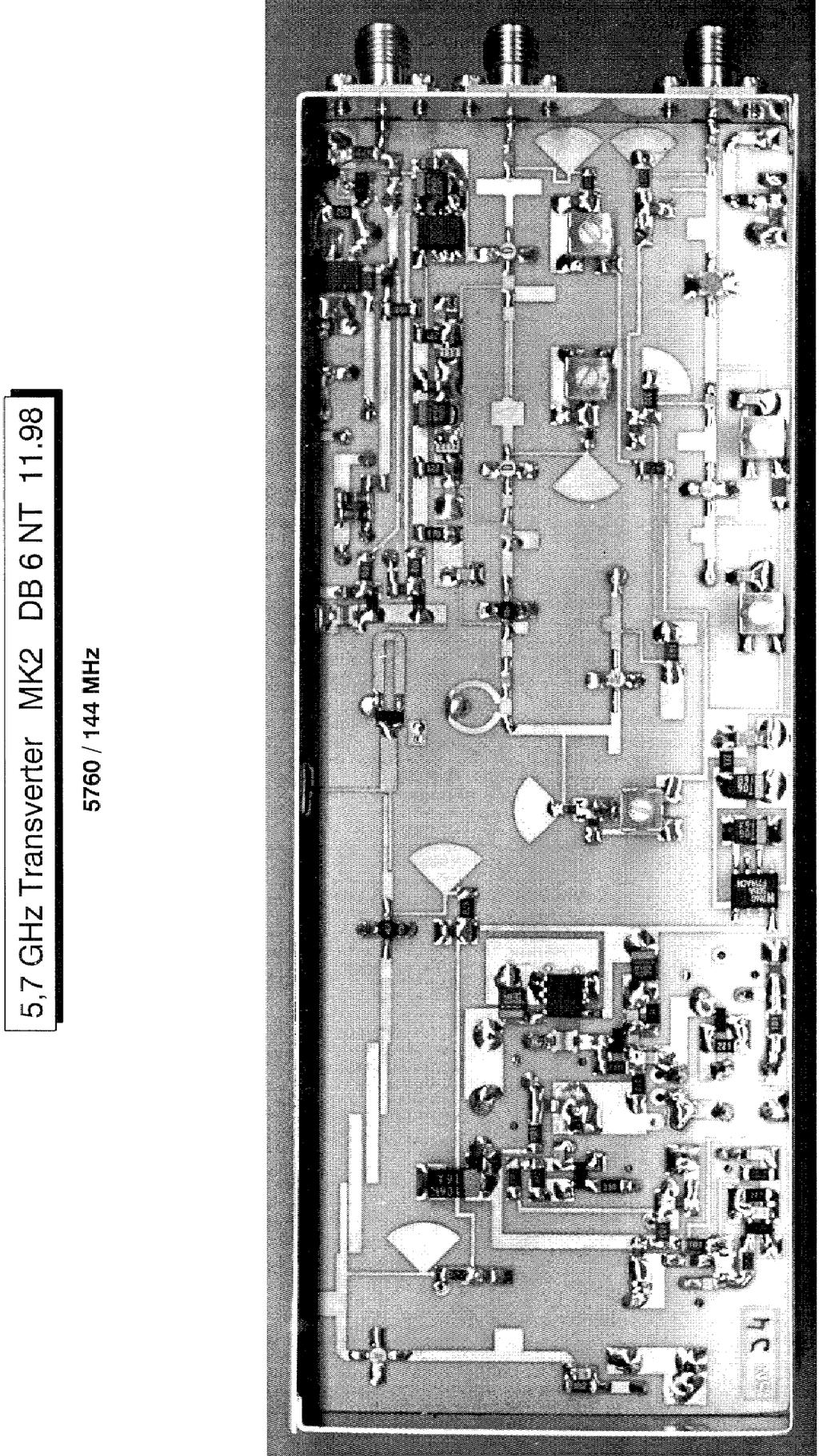
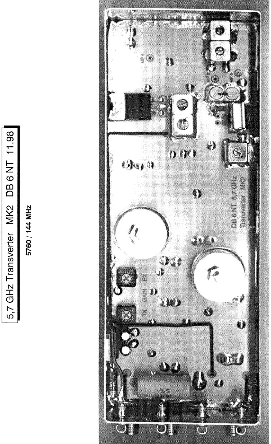
2 5,7 GHz Transverter MK2 DB6NT Generation Indroduction In 1977 the DUBUS magazine published the first 5,7GHz SSB transverter which had been developed by Claus Neye, DL7QY. This was the begin of using narrowband techniques in the 3cm band. The construction technique at that time utilised the classical waveguide approach the first transceiver on a PTFE-substrate has been described by DC0DA and DJ6EP. The circuits used have been realised with GaAs-FETs. Several modules were `screwed` together. The alignment effort to make this transceiver working has been considerable. The current transverter is a singleboard construction on RO4003 substrate. The receiver has a noise figure of 1.0dB at more than 20dB gain. The transmitter achieves an output power of more than 200 mw. The IF is 144 MHz and the spurious rejection is better than 40dB. If you will use 432 MHz IF, you have to build in a 111 MHz crystal. The capacitors of the resonant circuit have to be changed into 22pF and 82pF instead 15pF and 68pF. The helical filters F1 and F2 have to changed with the filter types 252HEP-2956A (F1) and 367MN-101A. (F2). Additional modifications of the circuit are not necessary. Then the spurious rejection is even better at least 50dB. Everything -TX, RX, LO, IF-Switch and T/R-control is on a single board housed in a 55x148x30mm large box from tinplate. Tuning is required only for the two cavity resonators, the four helix bandfilter in the LO-Chain and the bias currents of the TX/RX amplifiers. The restricted tuning range of the helix filters make `false`resonances not possible. Description: LO The proven `simple`xo uses the FET SST310 in a grounded gate circuit. The crystal frequency for a 144MHz IF is 117MHz. The coil is tuned by a M3 brass screw, which is fitted instead of the usual ferrite tuning screw. Extra pads are provided for fitting additional capacitors which can be selected for temperature compensation. For normal use in a restricted temperature change environment the stability is sufficient. But for more serious work a special ourtboard solution like the OCXO from DF9LN is required. This can be fed in at the source of the SST310, as indicated in the circuit diagram. The crystal and the heater have to be removed in this case. The XO is followed by a tripler to 351 MHz which utilises a BFR92A transistor. The third harmonic is filtered by a heilix bandfilter and drives the doubler with the BFP196. The output filter sieves the harmonic at 702 MHz. A second doubler with a BFP196 achieves an output frequency of 1404 MHz. The subsequent helix bandfilter is tuned to 1404MHz.
3 Now the chain of bipolars ends and the 1.404GHz signal driveds a GaAs-FET quadoupler with a MGF A microstrip edge coupled filter selects the LO frequency of 5616MHz and drives a further linear amplifier equipped with the ERA- 2SM MMIC. The power at this point is around 5mW (7dBm). Mixer The LO drives a single balanced diode mixer which uses a BAT15-99 low barrier double diode. The IF-port of the mixer is terminated by selectable attenuators for transmit and receive. These are switched by PIN-Diodes BAR64-03W to a common IF-connector. A voltage of at least +9V, which can be supplied by a FT-290 for example, activates the T/R-switching. Other brands of 2m transceivers have to be modified accordingly. Whilst this method of T/R-switching via the IF coaxial cable is quite elegant, also a separate method via the PTT-MAN input can be accomplished. An extra output is fitted for TX+, which can be used for external coaxial relays or PAs. This output must be guarded by a 0.63A fuse. It is not safe in case of short circuit! On the RF-port of the mixer a cavity resonator cares for sufficient suppression of spurious responses. RX The RX-chain uses two HEMT-Amplifiers ( NE32584C) and a third stage with a ERA3 SM MMIC. The gain of >30dB makes an extra IF-amplifier obsolete. The stages are coupled with simple microstripline filters. The last stage is coupled to the mixer filter via a Wilkinson divider. TX Two stages with MGF-1907 follow the Wilkinson divider. A subsequent cavity resonator cares for additional selectivity in the TX-chain needed for suppression on the LO. Two further stages with a MGF-1907 and a MGF-1601 amplify the signal to a power of 200mW. A directional coupler with a BAT15-03W Schottky diode allows for a monitor voltage of the RF output power. Construction To achieve a successful construction of this transverter the builder has to have experiences in the use and handling of SMD-parts. Furthermore experiences with smaller projects in microwave circuits are valuable. In any case the construction of this Transverter is not a beginners project.
4 The usual ESD protection measures should be obeyed. (see Fig. 5 for an excellent survey). Construction Steps 1. Solder the walls of the tinplate box and trim the PCB for fitting into the tinplate box. Please caution! Be careful! The tinplate has sharp edge, do not hurt you! 2. Mark the holes for the SMA-connectors. 3. Drill holes for SMA-connectors and feed-through caps. 4. Solder PCB into the box (Fig.4) Use a 10.2 mm High piece of wood as a ruler to find the right adjustment. 5. Solder the coupling rivets for the cavity resonators. They must stand upright! 6. Tin the bottom of the resonators. Mark the correct position with a pair of dividers. Fit a short M4 screw to the resonator. Put the resonator onto the position marked and heat the screw with a soldering iron. If the resonator is on the right temperature solder at the bottom. 7. Mount the parts onto the PCB (Fig.3). Mount the foodthrough caps. Solder the helix filters (Fig.4). Solder the regulators with their heatsinks to the wall of the tinplate box. Clean the finished PCB with alcohol. The tuning screws of the resonators should be removed. Dry the module in a stove (1h at 80 C) or cover night lying on a central heating. Alignment The following steps are necessary for the alignment of the transverter: 1. Apply 12V. Use a current limited (<0.6A) power supply. Check the voltage at the output of the fixed voltage regulators. 2. Measure the collector voltage at the BFR92A (Testpoint M1). Turn the tuning screw of the oscillator coil until the decrease of the collector voltage indicates the proper oscillation. The measurement should read around 7.2V. 3. Measure voltage at M2 (Fig. 2). Tune bandfilter F1 (351MHz) to minimum voltage (ca...6v) at M2. 4. Measure voltage at M3 (Fig. 2). Tune bandfilter F2 (702 Mhz) to minimum voltage (ca...4.8v) at M3. 5. Measure voltage at M4 (Fig. 2). Tune bandfilter F3 (1404 MHz) to maximum voltage (ca V) at M4.
5 6. Connect dummy load or antenna at input connector of RX. 7. Adjust 10k pots for a reading of 2V at the drain of the two RX-transistors NE32584C. 8. Connect 2m receiver at IF connector. Turn RX-Gain and TX-gain pots fully CCW. Adjust M4 tuning screw at resonator in front of mixer slowly clockwise (inwards) until you observe an increase in noise level. This is the upper sideband on 5760 MHz. For verification turn the tuning screw further inwards until you observe a second peak in noise level. This is the lower sideband on 5372 MHz. Turn back to the first maximum (Tuning screw is less inside the resonator) and lock with the security nut. 9. Switch transverter to transmit by grounding the PTT input. Connect a 50 Ohm dummy load to the RX output. Adjust all FETs in the TX-chain by the appropriate bias pots to the drain voltage given in the circuit diagram (Fig. 2). Drive the transverter with W on 144 MHz. Measure the monitor voltage at MON OUT. Only adjust the resonator in the TX-chain to a maximum by careful tuning. There is only one maximum, because the first resonator has already been tuned in the step before. Lock the tuning screw with a security nut. A fine tuning can be carried out by optimising the first resonator (in front of the mixer) and the bias currents of the TX transistors. 10. Reduce the TX-gain by clockwise rotation of the TX-gain pot until the TX output starts to decrease. 11. Connect antenna to RX input. Adjust the XO until a known beacon reads the correct frequency. 12. Take low resistance carbonised foam and glue it into the bottom cover. This damps the resonances of the box. Ready for use, good DX! Acknowledgement My special thanks to Lorenz DL6NCI. His support and the discussions were mandatory for the success of this development. Also my thanks to Richard, DF5SL, who verified the reproducibility of the design by building this transverter.
6 Literatur/References: 1.) ROGERS Leiterplattenmaterial Firma Mauritz Hamburg Datenblatt RO ) NEC Datenblatt NE32584C 3.) MITSUBISHI Datenbuch GaAs FET s 4.) SIEMENS Datenbuch RF- Halbleiter 5.) NEOSID Datenbuch Helixfilter 6.) TOKO Datenbuch Helixfilter 7.) Transverter for 5,7 GHz by DB6NT DUBUS 3.91 (DUBUS Buch III) 8.) 8 W GaAs-FET Amplifier for 6 cm DB6NT DUBUS 3.92 (DUBUS Buch III) 9.) P-HEMT LNA for 6 cm DJ9BV DUBUS 1.95 (DUBUS Buch IV) Bezug/Kits: Ready made units or kits: KUHNE electronic GmbH, Scheibenacker 3 D BERG Tel.: 0049 (0) Fax: 0049 (0) kuhne.db6nt@t-online.de All rights at the author DB 6 NT Michael Kuhne
7
8
9
10
11
12
13
14
15
16
17
Handbook / Kit. DB 6 NT 2,3 GHz Transverter MK DB 6 NT
 Handbook / Kit DB 6 NT 2,3 GHz Transverter MK2 4.2003 DB 6 NT 2.3 GHz Transverter MK2 DB6NT 4.2003 Introduction This transverter is a further development of the schematic published in 1993. Technical data
UHNE electronic GmbH
 UHNE electronic GmbH MICROWAVE COMPONENTS 2.3 GHz Transverter MK2 DB6NT 4.23 Introduction This transverter is a further development of the schematic published in 1993. Technical data of the assembly were
The 144MHz Anglian 3 transverter
 The 144MHz Anglian 3 transverter A high performance 144/28MHz transverter G4DDK document issue 1 12/9/16 Introduction Anglian 3 is an update to the 144MHz Anglian 2 transverter. The Anglian 2 is no longer
DEM Part Number L144-28INTCK 144 MHz Transverter Kit and complete kit
 DEM Part Number L144-28INTCK 144 MHz Transverter Kit and complete kit Power Out: Noise Figure and Gain: DC Power Requirement: 50 mw linear minimum 3.5 db NF nominal, 5 dbg maximum 12-15.5 VDC, 13.8 nominal
Construction Manual 4m-Linear-Transverter XV4-15
 Construction Manual 4m-Linear-Transverter XV4-15 Holger Eckardt DF2FQ Kirchstockacherstr. 33 D-85662 Hohenbrunn 3207 Technical data exciter frequency: 21.0... 21.5 MHz RF frequency: 70.0.. 70.5 MHz supply
Components for modular microwave transverters. Wolf-Henning Rech DF9IC in JN48iw
 Components for modular microwave transverters Wolf-Henning Rech DF9IC in JN48iw http://www.df9ic.de Content Multiband transverter systems Filters and multiplexers PLL-disciplined oscillators Transverters
Construction Manual 6m-Linear-Transverter XV6/10
 Construction Manual 6m-Linear-Transverter XV6/10 Holger Eckardt DF2FQ Kirchstockacherstr. 33 D-85662 Hohenbrunn 2606 Technical data exciter frequency: 28... 30 MHz RF frequency: 50... 52 MHz supply voltage:
Price-list for microwave components radio amateur list - date All prices are including 16% V.A.T
 Kuhne electronic GmbH Scheibenacker 3 D-95180 Berg/Oberfr. Germany Phone +49 9293-800939 Fax +49 9293-800938 Email: info@kuhne-electronic.de Internet: http ://www.db6nt.de Price-list for microwave components
Pricelist for Microwave Components radio amateur list - last update All prices include 19% V.A.T
 Kuhne electronic GmbH Scheibenacker 3 D-95180 Berg/Oberfr. Germany Phone 09293-800939 Fax 09293-800938 Email: info@kuhne-electronic.de Internet: http://www.db6nt.de Pricelist for Microwave Components radio
VHF,UHF and SHF TRANSVERTERS. by Kevin Murphy ZL1UJG
 VHF,UHF and SHF TRANSVERTERS by Kevin Murphy ZL1UJG 1 Topics in Presentation History of Transverters Generic design Band by band analysis:- What transverters are available (commercial :- new and used,
NEW DESIGN***DEM Part Number FRS***NEW DESIGN Low power 144 MHz Transverter for the Flex Radio System SDR-1000 Operating Specifications:
 NEW DESIGN***DEM Part Number 144-28FRS***NEW DESIGN Low power 144 MHz Transverter for the Flex Radio System SDR-1000 Operating Specifications: Operating Voltage: 12.0-15.5 VDC, 13.8 nominal Current Drain:
134GHz Transverter Roger Ray G8CUB
 134GHz Transverter Roger Ray G8CUB Synthesiser 11.20 GHz x3 33.6GHz amp IF o/p 440MHz harmonic mixer Tx path Pre-amp 134GHz 20dB Simplified 134GHz transverter block diagram The idea for a 134Ghz system
DEM TC DEM TRANSVERTER CONTROL
 DEM TC DEM TRANSVERTER CONTROL The DEM Transverter Control (DEM TC) is the circuit board that controls all transverter functions in the DEMI 2.3 GHz. -10 GHz. transverters. It was designed with many options
2-Tone Generator For 145Mhz
 Wolfgang Schneider, DJ8ES 2-Tone Generator For 145Mhz An RF amplifier stage is not only classified by amplification, which is as high as possible, and thus by its maximum output. What is frequently not
Frequency Generator (Wobbler) to 4GHz
 to 4GHz") Wolfgang Schneider, DJ8ES Frequency Generator (Wobbler) to 4GHz The following article describes a frequency generator with a wobble function for the frequency range from 10 MHz to 4 GHz. The output is
Wolfgang Schneider, DJ8ES Frequency Generator (Wobbler) to 4GHz The following article describes a frequency generator with a wobble function for the frequency range from 10 MHz to 4 GHz. The output is
23cm PSK packet-radio RTX for 1.2Mbit/s user access Matjaz Vidmar, S53MV
 23cm PSK packet-radio RTX for 1.2Mbit/s user access --------------------------------------------------Matjaz Vidmar, S53MV 1. Why biphase PSK modulation? -----------------------------Upgrading the packet-radio
Updating KK7B, SHF,DEM or DEMI 900 and 1296 MHz. transverters
 Updating KK7B, SHF,DEM or DEMI 900 and 1296 MHz. transverters By Steve Kostro, N2CEI PREFACE: Yes, It may be hard to believe, but the original 900 and 1296 No-Tune transverter concepts have been around
Alcatel White Box 24GHz Transceiver experiments and modifications
 Alcatel White Box 24GHz Transceiver experiments and modifications A set of working notes, measurements and comments PSU Need to supply : -5V up to ~ 30mA for Rx and PA modules +5.2V 1A for Rx and Tx mixer
Varactor-Tuned Oscillators. Technical Data. VTO-8000 Series
 Varactor-Tuned Oscillators Technical Data VTO-8000 Series Features 600 MHz to 10.5 GHz Coverage Fast Tuning +7 to +13 dbm Output Power ± 1.5 db Output Flatness Hermetic Thin-film Construction Description
Directly Synthesized 47 GHz Local Oscillator. Garry C. Hess, K3SIW February 18, 2007
 Directly Synthesized 47 GHz Local Oscillator Garry C. Hess, K3SIW February 18, 2007 Introduction. This note describes a means of directly synthesizing the local oscillator for a 47 GHz transverter. The
PA FAN PLATE ASSEMBLY 188D6127G1 SYMBOL PART NO. DESCRIPTION. 4 SBS /10 Spring nut. 5 19A702339P510 Screw, thread forming, flat head.
 MAINTENANCE MANUAL 851-870 MHz, 110 WATT POWER AMPLIFIER 19D902797G5 TABLE OF CONTENTS Page DESCRIPTION.............................................. Front Page SPECIFICATIONS.................................................
G6ALU 20W FET PA Construction Information
 G6ALU 20W FET PA Construction Information The requirement This amplifier was designed specifically to complement the Pic-A-Star transceiver developed by Peter Rhodes G3XJP. From the band pass filter an
DEM Part Number K, CK and LPK and CK 5.7 GHz. Transverter, Low Power Transverter, Kit and Complete Kit
 DEM Part Number 5760-144K, CK and 5760-144LPK and CK 5.7 GHz. Transverter, Low Power Transverter, Kit and Complete Kit Specifications Frequency: 5760.000 = 144.000 standard Noise Figure and Gain < 1.5
DB6NT 10 GHz transverter HitS & kinks. F5DQK November GHz DB6NT hits & kinks
 DB6NT 10 GHz transverter HitS & kinks 1 Abstract 1- LO Pout improvement 2- Gain / Nf measurement 3- DB6NT V2 with external 106.5 MHz OCXO input 4- I3OPW 106.5 MHz OCXO 5- DB6NT V3 with external 10 MHz
Dual Band Filter Assembly Manual
 Dual Band Filter Assembly Manual 12 January 2018 Rev D Version Theory of Operation: The purpose of a Bandpass Filter is to filter out or reject all unwanted signals. The original KN-Q7A Receive Filter
Varactor-Tuned Oscillators. Technical Data. VTO-8000 Series. Pin Configuration TO-8V
 H Varactor-Tuned Oscillators Technical Data VTO-8 Series Features 6 MHz to.5 Coverage Fast Tuning +7 to + dbm Output Power ±1.5 db Output Flatness Hermetic Thin-film Construction Description HP VTO-8 Series
Modifying the Qualcomm 1W Ku-Band PA for use on 3.4, 5.7 or 10.3 GHz
 Web Version 10-9-2001 Modifying the Qualcomm 1W Ku-Band PA for use on 3.4, 5.7 or 10.3 GHz K-Banke- 07/13/01 Hundreds of Ku-Band Qualcomm 1 watt power amplifiers have been modified and found their way
Low Cost Intermediate 144 MHz Transverter Kit DEM Part Number DC
 Low Cost Intermediate 144 MHz Transverter Kit DEM Part Number 144-28DC Operational Overview: The DEM 144-28DC is a low power, high performance 144 MHz to 28 MHz transmit and receive converter. It is intended
The K290R Project. Steve Kavanagh, VE3SMA, December 2017
 The K290R Project Steve Kavanagh, VE3SMA, December 2017 Background I have been using a pair of Yaesu FT-290R 2m transceivers as IF rigs for microwave transverters for many years. My 2.3, 3.4, 5.7, 10 and
Developing a 1296 MHz Beacon. By Kevin Murphy ZL1UJG April 2009
 Developing a 1296 MHz Beacon By Kevin Murphy ZL1UJG April 2009 1 Stage Functions Oscillator Module Multiplier Module Amplifier Module Keyer PSU Module Circulator/Filter 2 A good start for an oscillator
INC. MICROWAVE. A Spectrum Control Business
 DRO Selection Guide DIELECTRIC RESONATOR OSCILLATORS Model Number Frequency Free Running, Mechanically Tuned Mechanical Tuning BW (MHz) +10 MDR2100 2.5-6.0 +10 6.0-21.0 +20 Free Running, Mechanically Tuned,
DEM Part Number K, CK and LPK and CK 5.7 GHz. Transverter, Low Power Transverter, Kit and Complete Kit
 DEM Part Number 5760-144K, CK and 5760-144LPK and CK 5.7 GHz. Transverter, Low Power Transverter, Kit and Complete Kit Specifications Frequency: 5760.000 = 144.000 standard Noise Figure and Gain < 1.5
Conversion of a Marconi Blue Cap LNB into a 3cms 30-50mW Tx.
 Conversion of a Marconi Blue Cap LNB into a 3cms 30-50mW Tx. These mods. are based on the article by Bob Platts, G8OZP, in CQ-TV 181 P64-68. In this variation the various bias voltages are generated from
A 1269MHz Transmit Converter with 70cm IF input
 A 1269MHz Transmit Converter with 70cm IF input By Bertrand Zauhar, VE2ZAZ Email: ve2zaz@amsat.org Website: http://www3.sympatico.ca/b.zauhar AO-40 s Mode L-S is undoubtedly growing in popularity. This
This article describes the design of a multiband,
 A Low-Noise Amplifier for 2 GHz Applications Using the NE334S01 Transistor By Ulrich Delpy NEC Electronics (Europe) This article describes the design of a multiband, low-noise amplifier (LNA) using the
144MHz direct conversion receiver with I/Q outputs for use with Software Defined Radio.
 144MHz direct conversion receiver with I/Q outputs for use with Software Defined Radio. Overview This design is a direct conversion receiver for 144MHz with quadrature outputs for use either with a software
Amateur Microwave Communications. Ray Perrin VE3FN, VY0AAA April 2010
 Amateur Microwave Communications Ray Perrin VE3FN, VY0AAA April 2010 Introduction Microwaves are the frequencies above 1000 MHz More than 99% of the radio amateur frequency allocation is in the microwave
High Dynamic Range 70CM Transverter Kit DEM Part Number K or CK
 High Dynamic Range 70CM Transverter Kit DEM Part Number 432-28K or CK Operating Voltage: Current Drain: Output Power: TX Drive level Receive Noise Figure and gain: Operating Specifications: 11.0-16.5 VDC,
77 GHz VCO for Car Radar Systems T625_VCO2_W Preliminary Data Sheet
 77 GHz VCO for Car Radar Systems Preliminary Data Sheet Operating Frequency: 76-77 GHz Tuning Range > 1 GHz Output matched to 50 Ω Application in Car Radar Systems ESD: Electrostatic discharge sensitive
Instructions for building the PGA432 70cm preamplifier
 Instructions for building the PGA432 70cm preamplifier Issue 0.2 17/11/16 First step Carefully place the PCB, track side up, inside the lid of the tinplate box. Ensure that the PCB is centrally located.
A 3 Watt LDMOS Driver for the 432MHz band
 A 3 Watt LDMOS Driver for the 432MHz band John C Worsnop. PhD CEng MIET, G4BAO Introduction The popularity of my 2.5-Watt driver kit for the 1296MHz band (1) and the recent publication of G4DDK s Iceni
HT-1A Dual Band CW QRP Transceiver. Kit Building Instructions
 HT-A Dual Band CW QRP Transceiver Kit Building Instructions Rev B, July 8, 08 Designed by BD4RG Exclusively distributed by CRKITS.COM and its worldwide distributors Join the group http://groups.io/g/crkits
Spectrian 2304 MHz SSPA. Garry C. Hess, K3SIW June 11, 2004
 Spectrian 2304 MHz SSPA Garry C. Hess, K3SIW June 11, 2004 A solid-state power amplifier (SSPA) manufactured by Spectrian can produce on the order of 200 W linear output 1 at 2304 MHz with little modification.
PA1.3-2 Linear Amplifier Mini-kit
 PA1.3-2 Linear Amplifier Mini-kit Construction and operating notes Version 1.1 January 2001 (Version 2 PCB shown the PCB has been up-issued to version 3) 1 Introduction The PA1.3-2 is a low power amplifier
S-Band 2.4GHz FMCW Radar
 S-Band 2.4GHz FMCW Radar Iulian Rosu, YO3DAC / VA3IUL, Filip Rosu, YO3JMK, http://qsl.net/va3iul A Radar detects the presence of objects and locates their position in space by transmitting electromagnetic
DEM Part Number CK and LPCK 10 GHz. Transverter, Low power Transverter, Kit and Complete Kit
 DEM Part Number 10368-144CK and 10368-144LPCK 10 GHz. Transverter, Low power Transverter, Kit and Complete Kit Specifications Frequency: 10368.000 = 144.000 standard Noise Figure and Gain < 1.5 db NF,
Construction Guide of TH300S
 Construction Guide of TH300S TH300S is a 2-band SSB/CW transceiver, used with DDS as LO, and features dual operation system ham band and general coverage band. A doubly balanced diode ring mixer is used
SPECIFICATIONS: Subcarrier Frequency 5.5MHz adjustable, FM Modulated +/- 50KHz. 2nd 11MHz >40dB down from 5.5MHz
 Mini-kits AUDIO / SUBCARRIER KIT EME75 Version4 SPECIFICATIONS: Subcarrier Frequency 5.5MHz adjustable, FM Modulated +/- 50KHz Subcarrier Output 1.5v p-p Output @ 5.5MHz DESCRIPTION & FEATURES: The Notes
Hendricks QRP Kits BITX20A to BITX17A Conversion Instructions
 Hendricks QRP Kits BITX20A to BITX17A Conversion Instructions 30 November 2008 Converting your BITX20A Kit to a BITX17A Kit is not all that complex. It only requires that you change crystals and some resonance
MAINTENANCE MANUAL RF BOARD 19D901835G1 ( MHz) 19D901835G2 ( MHz) FOR MVS
 19D901835G2 ( MHz) FOR MVS") D MAINTENANCE MANUAL F BOAD 19D901835G1 (136-153 MHz) 19D901835G2 (150-174 MHz) FO MVS TABLE OF CONTENTS DESCIPTION............................................... Front Cover CICUIT ANALYSIS..............................................
D MAINTENANCE MANUAL F BOAD 19D901835G1 (136-153 MHz) 19D901835G2 (150-174 MHz) FO MVS TABLE OF CONTENTS DESCIPTION............................................... Front Cover CICUIT ANALYSIS..............................................
10 GHz Microwave Link
 10 GHz Microwave Link Project Project Objectives System System Functionality Testing Testing Procedures Cautions and Warnings Problems Encountered Recommendations Conclusion PROJECT OBJECTIVES Implement
HAMTRONICS TB901 FM EXCITER INSTALLATION, OPERATION, & MAINTENANCE
 HAMTRONICS TB901 FM EXCITER INSTALLATION, OPERATION, & MAINTENANCE GENERAL INFORMATION. The TB901 is a single-channel low power fm transmitter (exciter) designed to provide 300-600 milliwatts continuous
A NEW LIFE FOR THE FT-290R TRANSCEIVER! By F5RCT
 A NEW LIFE FOR THE FT-290R TRANSCEIVER! By F5RCT The FT290R is an old amateur radio workhorse which was a very popular transceiver during the 80 s. It is a 2metre multimode portable which can run with
Oscillator for 122GHz: Frequency multiplier from 61GHz and amplifier
 Sigurd Werner, DL9MFV Oscillator for 122GHz: Frequency multiplier from 61GHz and amplifier The design of a passive frequency doubler and a sub-harmonic mixer for 122GHz requires a strong signal on 61GHz.
5.5 GHz to 8.6 GHz, GaAs, MMIC, I/Q Upconverter HMC6505A
 Data Sheet FEATURES Conversion gain: db typical Sideband rejection: dbc typical Output P1dB compression at maximum gain: dbm typical Output IP3 at maximum gain: dbm typical LO to RF isolation: db typical
1 FUNCTIONAL DESCRIPTION WAY SPLITTER/INPUT BOARD FET RF AMPLIFIERS WAY POWER COMBINER VSWR CONTROL BOARD...
 CONTENTS 1 FUNCTIONAL DESCRIPTION...1 2 4-WAY SPLITTER/INPUT BOARD...2 3 FET RF AMPLIFIERS...3 4 4-WAY POWER COMBINER...4 5 VSWR CONTROL BOARD...5 6 ADJUSTMENT OF BIAS VOLTAGE TO ESTABLISH PROPER QUIESCENT
Manufacturers of RF and Microwave Components and Assemblies Specialist in RF Filters, Power amplifiers and RF Switches
 Manufacturers of RF and Microwave Components and Assemblies Specialist in RF Filters, Power amplifiers and RF Switches sales@cormic.com www.cormic.com P 724.940.7556 F 724.940.7707 RF & MICROWAVE FILTERS
DEVELOPMENT AND PRODUCTION OF HYBRID CIRCUITS FOR MICROWAVE RADIO LINKS
 Electrocomponent Science and Technology 1977, Vol. 4, pp. 79-83 (C)Gordon and Breach Science Publishers Ltd., 1977 Printed in Great Britain DEVELOPMENT AND PRODUCTION OF HYBRID CIRCUITS FOR MICROWAVE RADIO
High quality products made in Germany
 High quality products made in Germany UHNE electronic GmbH Microwave components Englisch 2005 - Main catalogue UHNE electronic GmbH MICROWAVE COMPONENTS Innovative high quality products using advanced
GaAs MMIC devices are susceptible to Electrostatic Discharge. Use proper ESD precautions when handling these items.
 The is a broadband, power efficient GaAs PHEMT distributed amplifier in a 4mm QFN surface mount package. The is designed to provide optimal LO drive for T3 mixers. Typically, ADM-26-2931SM provides. db
Features. = +25 C, Vcc = +3V
 Typical Applications Low noise MMIC VCO w/buffer Amplifi er for: VSAT & Microwave Radio Test Equipment & Industrial Controls Military Features Pout: +dbm Phase Noise: -106 dbc/hz @100 khz No External Resonator
CAVITY TUNING. July written by Gary Moore Telewave, Inc. 660 Giguere Court, San Jose, CA Phone:
 CAVITY TUNING July 2017 -written by Gary Moore Telewave, Inc 660 Giguere Court, San Jose, CA 95133 Phone: 408-929-4400 1 P a g e Introduction Resonant coaxial cavities are the building blocks of modern
10 GHz LNA for Amateur Radio by K5TRA
 Introduction Ham radio operation on 10 GHz is somewhat exotic. This is far removed from global short-wave communication below 30 MHz, or regional VHF and UHF communication. Despite the arcane nature of
Beta-test ED1 PCB installed in I0CG s K1
 K1 SSB Modification (Ed.2) This description provides the receiver (RX) modifications, assembly, alignment and operation as a first step. In a second step you can add the remaining transmitter (TX) modifications,
Bitx Version 3 Linear Amplifier Assembly
 Bitx Version 3 Linear Amplifier Assembly The power supply section has 2 options. 1 - AC input and a higher voltage on the IRF510 and +12 volts to the bitx. 2 - +12 volts applied to both the final and the
Weekend VHF/UHF Power Amplifier
 www.svet-el.si/english AX elektronika d.o.o. Špruha 33 1236 TRZIN SLOVENIA Magazine publisher tel.: 00386 1 549 14 00 tel.:00386 1 528 26 88 fax: 00386 1 528 56 88 prodaja04@svet-el.si www.svet-el.si Weekend
RF amplifier 70MHz on RA30H0608M
 RF amplifier 70MHz on RA30H0608M Peter SP2DMB 19.08.2014r. sp2dmb@gmail.com www.sp2dmb.blogspot.com www.sp2dmb.cba.pl The availability of a hybrid power amplifier allows easy to built RF power amplifier
High Dynamic Range 144 MHz Transverter Kit DEM Part Number K or CK
 High Dynamic Range 144 MHz Transverter Kit DEM Part Number 144-28K or CK Operational Overview: The DEM 144-28 is a 144 MHz to 28 MHz transmit and receive converter. It will operate with most High Frequency
Features. = +25 C, Vcc = +3V
 Typical Applications Low noise MMIC VCO w/buffer Amplifi er for: Wireless Local Loop (WLL) VSAT & Microwave Radio Test Equipment & Industrial Controls Military Features Pout: +4.9 dbm Phase Noise: -3 dbc/hz
BROADBAND DISTRIBUTED AMPLIFIER
 ADM1-26PA The ADM1-26PA is a complete LO driver solution for use with all Marki mixers up to 26. GHz. This single-stage packaged GaAs MMIC distributed amplifier integrates all required biasing circuitry.
Keywords: ISM, RF, transmitter, short-range, RFIC, switching power amplifier, ETSI
 Maxim > Design Support > Technical Documents > Application Notes > Wireless and RF > APP 4929 Keywords: ISM, RF, transmitter, short-range, RFIC, switching power amplifier, ETSI APPLICATION NOTE 4929 Adapting
21 GHz to 27 GHz, GaAs, MMIC, I/Q Upconverter HMC815B
 Data Sheet 1 GHz to 7 GHz, GaAs, MMIC, I/Q Upconverter HMC1B FEATURES Conversion gain: db typical Sideband rejection: dbc typical OP1dB compression: dbm typical OIP3: 7 dbm typical LO to RF isolation:
GaAs MMIC devices are susceptible to Electrostatic Discharge. Use proper ESD precautions when handling these items.
 ADM-26-931SM The ADM-26-931SM is a broadband, power efficient GaAs PHEMT distributed amplifier in a 4mm QFN surface mount package. The ADM-26-931SM is designed to provide optimal LO drive for T3 mixers.
KN-Q10 Assembly Manual
 KN-Q10 Assembly Manual Translated by Adam Rong, BD6CR/4 with permission from Ke Shi, BA6BF Edited by Stephen, VK2RH Revision B, Oct 14, 2010 Thank you for purchasing the KN-Q10 4 Band SSB/CW Dual Mode
MAINTENANCE MANUAL MDX POWER AMPLIFIER BOARDS 19D904792G2 ( MHz) 19D904792G1 ( MHz) 19D904792G3 ( MHz)
 19D904792G1 ( MHz) 19D904792G3 ( MHz)") MAINTENANCE MANUAL MDX POWER AMPLIFIER BOARDS 19D904792G2 (403-440 MHz) 19D904792G1 (440-470 MHz) 19D904792G3 (470-512 MHz) TABLE OF CONTENTS Page DESCRIPTION... 1 CIRCUIT ANALYSIS... 1 SERVICE NOTES...
MAINTENANCE MANUAL MDX POWER AMPLIFIER BOARDS 19D904792G2 (403-440 MHz) 19D904792G1 (440-470 MHz) 19D904792G3 (470-512 MHz) TABLE OF CONTENTS Page DESCRIPTION... 1 CIRCUIT ANALYSIS... 1 SERVICE NOTES...
Modification of Alcatel 9400UX Synthesisers By Roger Ray G8CUB - Updated
 Modification of Alcatel 9400UX Synthesisers By Roger Ray G8CUB - Updated Many Alcatel Outdoor Units have been purchased, for conversion to 24GHz. For some reason the synthesiser local oscillator is not
DEMI Part Number L432-28
 DEMI Part Number L432-28 SN Transverter Configuration Power Out Maximum: 25 W linear 50 W linear Other Noise Figure and Gain:
Read This Page First
 Read This Page First If you are reading this you know the manuals are always available at QRPKITS.com. This is version 8.0 of the manual dated 4/27/2016. There is no need to print out the whole assembly
GaAs MMIC Double Balanced Mixer. Description Package Green Status
 GaAs MMIC Double Balanced Mixer MM1-0212SSM 1. Device Overview 1.1 General Description The MM1-0212SSM is a highly linear GaAs MMIC double balanced mixer. MM1-0212SSM is a low frequency, high linearity
GaAs MMIC devices are susceptible to Electrostatic Discharge. Use proper ESD precautions when handling these items.
 ADM-12-931SM The ADM-12-931SM is a small, low power, and economical T3 driver or T3A pre-amplifier. It is a GaAs PHEMT distributed amplifier in a 3mm QFN surface mount package. The ADM-12-931SM can provide
DEMI Part Number L144-28
 DEMI Part Number L144-28 SN Transverter Configuration Power Out Maximum: 25 W linear 50 W linear Other Noise Figure and Gain:
Picture: Luit Popken PA0LPN Developed originally by G4WMX and GW3DIX, later improved by DK9NL. Latest improvements by DG0KW (version used by us)
") The X-Phase-2 QRM-killer Picture: Luit Popken PA0LPN Developed originally by G4WMX and GW3DIX, later improved by DK9NL. Latest improvements by DG0KW (version used by us) A hobby project of the local VERON
The X-Phase-2 QRM-killer Picture: Luit Popken PA0LPN Developed originally by G4WMX and GW3DIX, later improved by DK9NL. Latest improvements by DG0KW (version used by us) A hobby project of the local VERON
Directional Couplers / SWR detectors for 145MHz - 435MHz. Easily and cheaply made. pa0nhc. Ver. E4;
 1 of 9 12/1/2008 9:46 PM
MDT DSB TRANSCEIVER CONSTRUCTION MANUAL. MDT Construction Manual Issue 2 Page 1
 MDT DSB TRANSCEIVER CONSTRUCTION MANUAL MDT Construction Manual Issue 2 Page 1 CONTENTS 1 Introduction... 4 2 DSB vs SSB... 5 3 DSB transmitter... 6 4 Direct Conversion receiver... 7 5 MDT Block Diagram...
Hendricks QRP Kits The Twofer Rev
 Hendricks QRP Kits The Twofer Rev 1 11-15-06 1. Description The Twofer is a classic QRP transmitter that s easy to assemble and operate. It uses a JFET VXO (variable crystal oscillator), driver stage and
MAINTENANCE MANUAL. MDX POWER AMPLIFIER BOARDS 19D904792G2 ( MHz) 19D904792G1 ( MHz) 19D904792G3 ( MHz) TABLE OF CONTENTS
 19D904792G1 ( MHz) 19D904792G3 ( MHz) TABLE OF CONTENTS") LBI-39051C MAINTENANCE MANUAL MDX POWER AMPLIFIER BOARDS 19D904792G2 (403-440 MHz) 19D904792G1 (440-470 MHz) 19D904792G3 (470-512 MHz) TABLE OF CONTENTS Page DESCRIPTION... 1 CIRCUIT ANALYSIS... 1 SERVICE
LBI-39051C MAINTENANCE MANUAL MDX POWER AMPLIFIER BOARDS 19D904792G2 (403-440 MHz) 19D904792G1 (440-470 MHz) 19D904792G3 (470-512 MHz) TABLE OF CONTENTS Page DESCRIPTION... 1 CIRCUIT ANALYSIS... 1 SERVICE
MICROWAVE MICROWAVE TRAINING BENCH COMPONENT SPECIFICATIONS:
 Microwave section consists of Basic Microwave Training Bench, Advance Microwave Training Bench and Microwave Communication Training System. Microwave Training System is used to study all the concepts of
Amplifier Combining for High Power at 13cm. Dave Powis DL4MUP/G4HUP
 Amplifier Combining for High Power at 13cm Dave Powis DL4MUP/G4HUP Abstract With the availability of surplus RF power amplifiers from 1.9GHz Personal Communication Systems (PCS) capable of producing in
ILER MK2. Appendices
 ILER MK2 QRP SSB Transceiver in Kit Form Appendices Last update: July 20, 2015 ea3gcy@gmail.com Most recent updates and news at: www.qsl.net/ea3gcy ILER-17 MK2 SSB QRP Transceiver Kit Page 1 APPENDIX 1:
Features. = +25 C, Vdd1 = Vdd2 = +3.5V, Idd = 80 ma [2]
![Features. = +25 C, Vdd1 = Vdd2 = +3.5V, Idd = 80 ma [2]](/thumbs/94/119028866.jpg "Features. = +25 C, Vdd1 = Vdd2 = +3.5V, Idd = 80 ma [2]") Typical Applications This is ideal for: Features Low Noise Figure: 1.8 db Point-to-Point Radios Point-to-Multi-Point Radios Military & Space Test Instrumentation Functional Diagram High Gain: 19 db High
Typical Applications This is ideal for: Features Low Noise Figure: 1.8 db Point-to-Point Radios Point-to-Multi-Point Radios Military & Space Test Instrumentation Functional Diagram High Gain: 19 db High
13cm PSK transceiver for 1.2Mbit/s packet radio
 13cm PSK transceiver for 1.2Mbit/s packet radio Matjaž Vidmar, S53MV 1. Introduction The choice of a transceiver design for high-speed packet radio is not simple. Is it better to use an apparently simpler
A simple 3.4GHz transverter
 A simple 3.4GHz transverter A Geelong Amateur Radio Club Project 24 April 2016 Modifying a surplus 3.4GHz data transceiver for amateur operation Page 1 of 26 Acknowledgements...3 Introduction...3 Parts
4m amateur band transverter module Featuring a very high dynamic range receive converter and a spectrally clean transmit converter.
 (C) 2013 G4DDK 4m amateur band transverter module Featuring a very high dynamic range receive converter and a spectrally clean transmit converter. Sam Jewell, G4DDK 11/27/2013 This document describes the
MAINTENANCE MANUAL MHz, 100 WATT POWER AMPLIFIER 19D901841G3
 MAINTENANCE MANUAL 851-870 MHz, 100 WATT POWER AMPLIFIER 19D901841G3 TABLE OF CONTENTS SPECIFICATIONS............................................... Front Cover DESCRIPTION.................................................
Parameter Min. Typ. Max. Units
 v4.112 Typical Applications The is ideal for: Point-to-Point and Point-to-Multi-Point Radio Military Radar, EW & ELINT Satellite Communications Functional Diagram Features General Description The is a
This provides extremely fast tuning speed limited primarily by the internal impedance of the user-supplied voltage driver.
 Hyperabrupt Varactor-Tuned Oscillators Technical Data VTO-9 Series Features 32 to 2.3 GHz Coverage Fast Tuning Fast Setting Time +2 VDC Max Tuning Voltage 1 mw Output Power ±2. db Output Flatness Hermetic
Application Note 5011
 MGA-62563 High Performance GaAs MMIC Amplifier Application Note 511 Application Information The MGA-62563 is a high performance GaAs MMIC amplifier fabricated with Avago Technologies E-pHEMT process and
Overview of the MSA 12/30/10
 Overview of the MSA 12/30/10 Introduction The purpose of this document is to provide an overview of the capabilities and construction of the MSA to help potential builders get oriented. Much more detailed
Low Power GaAs MMIC Double Balanced Mixer. Refer to our website for a list of definitions for terminology presented in this table.
 Low Power GaAs MMIC Double Balanced Mixer MM1-0212LSM 1. Device Overview 1.1 General Description The MM1-0212LSM is a low power GaAs MMIC double balanced mixer that operates at LO powers as a low as +1
Maintenance Manual. MTD SERIES 900 MHz, 10-WATT, DATA ONLY MOBILE RADIO. Mobile Communications LBI TABLE OF CONTENTS
 Mobile Communications MTD SERIES 900 MHz, 10-WATT, DATA ONLY MOBILE RADIO TABLE OF CONTENTS RF BOARD............................... LBI-38545 AUDIO BOARD............................ LBI-38546 LOGIC BOARD............................