Techniques in solar polarimetry / magnetography
|
|
|
- Hannah Harper
- 5 years ago
- Views:
Transcription
1 Techniques in solar polarimetry / magnetography Achim Gandorfer MPS Contents What is polarimetry? Why polarimetry? sources of polarization in astrophysics description of polarized light observing principles polarimetric techniques modulation schemes demodulation 1
2 What is polarimetry? polarimetry is the art of quantitatively determine the degree of polarization of light. Why polarimetry polarization yields information that cannot be obtained via classical photometry, spectroscopy polarization information is add-on to intensity measurements, not in competition not looking for polarization is wasting information! Photons are expensive, make use of them! 2

3 (astrophysical) polarization light can be polarized by processes in which light interacts with matter and if as seen from the observer the rotational symmetry of the interaction process is broken. effects that create polarization reflection total reflection refraction scattering dichroism (synchrotron radiation) Zeeman effect (magnetic fields!) 3
 Hanle effect (magnetic")
4 Zeeman effect effects that alter polarization reflection refraction birefringence Faraday effect (magnetic fields) Hanle effect (magnetic fields) 4
5 Hanle effect Hanle effect: Modification of scattering polarisation (of spectral lines) in the presence of a magnetic field optical magnetometer Magnetometer = Wavelength selector + Polarimeter spectrograph spectropolarimeter monochromatic filter (filter) magnetograph 5


6 I Q U V Imaging spectropolarimetry 6
7 Nota bene! in this lecture: quantitative measurement of polarization, not of magnetic field!! no convertion from polarization maps magnetic field maps ( inversion techniques ) no interpretation description of polarized light light represented as electromagnetic tranverse wave polarization is related to the vibration plane of the electric field 7

8 2component vector containing complex E x, E y fields very convenient for description of elementary interaction processes only useful for idealised light: monochromatic! Jones formalism Stokes formalism Jones representation not adequate for real light: partially polarized light with non zero frequency bandwidth better for daily life: representation in terms of intensity, not amplitude time average over many periods (visible light: Hz!!!) allows description of white light, partially polarized, incoherent, undirected... Stokes representation (1852) 8
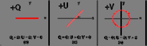
9 Stokes vector in the Stokes formulation light is represented by a four component vector I: I represents the ordinary scalar intensity, Q,U,V are differences of intensities practical meaning of the Stokes components I, Q, U, V are measurable quantities each parameter represents 1 dedicated measurement: 9


10 10
11 Stokes formalism advantages of the Stokes representation perfectly represents measurement procedure not restricted to monochromatic light can describe unpolarized light (classical radiative transfer equation can be formally expanded to vector equation by replacing scalar I with vector I) optical components acting on the Stokes vector can be very conveniently described by matrices ( Mueller matrices ) 11
12 Mueller matrices an optical component acts on a Stokes vector M is a 4x4 matrix optical train represented by matrix product of individual component matrices important Mueller matrices partial linear polarizer (0 o ) total linear polarizer (0 o ) retardation plate (phase retarder, birefringent element) (0 o ) always: 12
13 basic rules for Mueller matrices Mueller matrices can be multiplied attention: don t exchange components along the path!!!!! optical component M rotated by angle α : with rotation matrix Polarimetric basics polarimetry = differential photometry polarisation images are linear combinations of photometric or spectral images taken in different polarisation states 13
14 Q,U,V, and I Q,U,V mostly << I polarization degree Q/I (U/I,V/I) small (typically 10-4 <Q/I<10-2 ) detect small intensity difference on top of large intensity Example: detection of Stokes Q: two measurements: polarizer 0 o, 90 o I 1 =0.5(I+Q) I 2 =0.5(I-Q) I Q/I=(I 1 -I 2 )/(I 1 +I 2 ) normalized Stokes parameter : very accurate, since efficiency of detector I/2 Q divides out : differential measurement 14
15 Two basic techniques single beam polarimetry: Use of a modulator/polarizer combination to convert polarisation information into time-dependent intensity, sequential detection with one detector temporal modulation (single beam polarimeter) dual beam polarimetry: Use a polarising beam splitter to spatially separate both orthogonal polarisation states at the same time, simultaneous detection with two different detectors spatial modulation (dual beam polarimeter) Systematic error sources 1. seeing: I intensity changes during measurement : intensity difference has nothing to do with polarization t 15
16 Systematic error sources 1. seeing 2. gain-table or flat field : detector sensitivity varies from 1 exposure to the other signal difference has nothing to do with polarisation Systematic error sources 1. seeing 2. gain-table or flat field 3. photon noise: statistical character of photons σ~ N, N number of photons noise increases with number of photons, Signal-to-noise decreases! 16

17 How to do sensitive polarimetry? seeing noise gain table noise photon noise fast polarization modulation use identical detector elements for differential images increase statistic by frame averaging Dual beam polarimetry at THEMIS 17
 problems with flat-field and alignment of the two beams differential optical aberrations in both beams very limited accuracy without")
18 Dual beam polarimetry at THEMIS Dual beam polarimetry dual beam polarimetry to beat seeing induced errors (strictly simultaneously!) problems with flat-field and alignment of the two beams differential optical aberrations in both beams very limited accuracy without further trick 18
19 Beam exchange add half-wave modulator to beam-splitter half wave plate changes all signs in the polarization path, errors keep sign two images with two settings of wave plate (per Stokes parameter) four images yield fractional polarisation mostly free from systematic errors Beam exchange Semel-Donati technique (Semel, Donati, Rees, 1993) Ratios of images instead of differences! spatio-temporal modulation (Trujillo-Bueno et al. 2001) equivalent down to Dittmann et al
20 a simple polarimeter retardation plate, retardance δ, angle θ linear polarizer, fixed Intensity depends on δ, θ, and Q,U,V polarization modulation Q,U,V not directly measurable convert polarization information into intensity intensity depends on Q,U,V, δ,θ information about Q,U,V is encoded in I S (δ,θ) with S=Q,U,V modulation functions 20
21 modulation schemes for modulation you can use changes of delta, theta, or both of 1, 2, or more retardation plates rotating retardation plate a very simple but robust polarimeter consists of 1 rotating retardation plate and a linear polarizer with θ=ωt I S (t) with S=Q,U,V Q,U,V modulated at different frequencies, and phases! phase sensitive detection possible! 21
22 phase sensitive detection encode information into functions with known frequencies (modulation frequency) and phases from all signal fluctuations only detect those at exactly these frequencies, integrate the rest to zero! LOCK-IN principle choose modulation frequency such that it brings you out of the noise regime! I example: modulation with (fast) seeing and (slow) transmission change periodic modulation of Stokes parameter at known frequency high frequency spectrum due to seeing slow degradation of transmittance: slope t 22
23 similar, but now δ 1,2 fixed, θ 1,2 modulated! two modulators at two frequencies: Stokes V Stokes V Stokes U Modulators rotating (continuous or stepped) wave plate Advanced Stokes Polarimeter (Lites et al. 1990) Hinode (Solar B) spectropolarimeter (Lites 2001) POLIS (Schmidt et al. 2001) IRSOL polarimeter (Bianda et al. 1998) THEMIS (Paletou et al. 2001) Yunnan S 3 T telescope (Qu et al. 2001) 23
24 Modulators Liquid crystal retarders nematic liquid crystals electrically tuneable wave plates fixed fast optical axis slow (150ms rise time) Ferroelectric liquid crystals (FLCs) fixed retardance (NOT tuneable) switchable fast optical axis fast (150 µs rise and fall time) Nematic liquid crystals Potsdam polarimeter (Hofmann 2000; Horn and Hofmann, 1999) Haleakala Imaging Vector Magnetograph (Mickey et al. 1996) Big Bear Digital Video Magnetograph (Spirock et al. 2001) IMaX onboard SUNRISE Solar orbiter VIM 24
25 Ferroelectric Liquid crystals La Palma Stokes Polarimeter (Martinez-Pillet et al. 1999) Tenerife Infrared Polarimeter (TIP) (Collados et al. 1999) Zurich Imaging Polarimeter II (Gandorfer 1999) Near Infrared Magnetograph (Rabin et al. ) SOLIS VSM (Keller et al. 1998) demodulation of the modulated signal easiest way: read detector in synchronism with modulation drawbacks: detectors slow, photon flux low, dominatedbyreadnoise better: specialized detector architecture for on-chip demodulation 25
26 Zurich IMaging POLarimeter ZIMPOL II fast modulation/demodulation system polarisation modulation in the khz range special CCD sensor used as part of a synchronous demodulator Povel, H.P., 1995, Optical Engineering 34, 1870 ZIMPOL II: Components piezoelastic modulator or ferroelectric retarders allow polarisation modulation up to 84 khz Glan linear polarizer as analyser 3 out of 4 pixel rows covered with opaque mask 4 interlaced charge images can be handled simultaneously in the same CCD rapid charge shifting in synchronism with modulation 26
27 ZIMPOL II: Principle Gandorfer & Povel, 1997, A&A 328, 381 ZIMPOL II: Principle Gandorfer & Povel, 1997, A&A 328,
28 ZIMPOL II: Principle Gandorfer & Povel, 1997, A&A 328, 381 Extending the wavelength range near infrared large Zeeman splitting vs. complex detector technology CMOS sensors (Nicmos, Hawaii) Tenerife Infrared Polarimeter (TIP) Nicmos 3 detector FLC based spatio-temporal modulation (Collados et al. 1999) 28
29 Extending the wavelength range near ultraviolet chromospheric diagnostics vs. complex detector and modulator technology POLIS (standard blue sensitive backthinned CCDs; special rotating wave plate) ZIMPOL II (highly specialised CCD architecture; piezoelastic modulator) Instrumental polarisation optical elements before polarisation analysis change polarisation states avoid oblique reflections take care about thick windows with temperature gradients (stress induced birefringence) if not possible: make telescope model based on polarized ray tracing / geometry of telescope 29
Techniques in solar polarimetry / magnetography. Achim Gandorfer MPS
 Techniques in solar polarimetry / magnetography Achim Gandorfer MPS Contents What is polarimetry? Why polarimetry? sources of polarization in astrophysics description of polarized light observing principles
ZIMPOL-3: a powerful solar polarimeter
 ZIMPOL-3: a powerful solar polarimeter San Diego, SPIE, 1. July 2010 Renzo Ramelli, IRSOL, Locarno, Switzerland and the ZIMPOL team The ZIMPOL-3 team Silvano Balemi, SUPSI Michele Bianda, IRSOL Ivan Defilippis,
instruments Solar Physics course lecture 3 May 4, 2010 Frans Snik BBL 415 (710)
") Solar Physics course lecture 3 May 4, 2010 Frans Snik BBL 415 (710) f.snik@astro.uu.nl www.astro.uu.nl/~snik info from photons spatial (x,y) temporal (t) spectral (λ) polarization ( ) usually photon starved
Solar Physics course lecture 3 May 4, 2010 Frans Snik BBL 415 (710) f.snik@astro.uu.nl www.astro.uu.nl/~snik info from photons spatial (x,y) temporal (t) spectral (λ) polarization ( ) usually photon starved
Fast Solar Polarimeter. Alex Feller Francisco Iglesias Nagaraju Krishnappa Sami K. Solanki
 Fast Solar Polarimeter Alex Feller Francisco Iglesias Nagaraju Krishnappa Sami K. Solanki 013-10-01 1 FSP in a nutshell Novel ground-based solar imaging polarimeter developed by MPS in collaboration with
Tunable narrow-band filter for imaging polarimetry
 **FULL TITLE** ASP Conference Series, Vol. **VOLUME**, **YEAR OF PUBLICATION** **NAMES OF EDITORS** Tunable narrow-band filter for imaging polarimetry A. Feller 1, A. Boller 1, J.O. Stenflo 1,2 1 Institute
Fast Solar Polarimeter
 Fast Solar Polarimeter A. Feller, F. Iglesias, K. Nagaraju, S. K. Solanki Max Planck Institute for Solar System Research and colleagues from the Max Planck semiconductor lab A. Feller FSP IAUS 305 1 /
First observations with a new imaging polarimeter
 Astron. Astrophys. 328, 381 389 (1997) ASTRONOMY AND ASTROPHYSICS First observations with a new imaging polarimeter A.M. Gandorfer and H.P. Povel Institut für Astronomie, ETH-Zentrum, CH-8092 Zürich, Switzerland
arxiv: v1 [astro-ph.im] 31 Aug 2018
![arxiv: v1 [astro-ph.im] 31 Aug 2018](/thumbs/87/96036473.jpg "arxiv: v1 [astro-ph.im] 31 Aug 2018") Full Stokes polarimetry using Dual-Frequency Liquid Crystals K. Nagaraju a, D. V. S. Phanindra a, S. Krishna Prasad b, D. S. Shankar Rao b, and P. Sreekumar a a Indian Institute of Astrophysics, Koramangala
Full Stokes polarimetry using Dual-Frequency Liquid Crystals K. Nagaraju a, D. V. S. Phanindra a, S. Krishna Prasad b, D. S. Shankar Rao b, and P. Sreekumar a a Indian Institute of Astrophysics, Koramangala
An integral eld spectrograph for the 4-m European Solar Telescope
 Mem. S.A.It. Vol. 84, 416 c SAIt 2013 Memorie della An integral eld spectrograph for the 4-m European Solar Telescope A. Calcines 1,2, M. Collados 1,2, and R. L. López 1 1 Instituto de Astrofísica de Canarias
Lecture 7: Op,cal Design. Christoph U. Keller
 Lecture 7: Op,cal Design Christoph U. Keller Overview 1. Introduc5on 2. Requirements Defini5on 3. Op5cal Design Principles 4. Ray- Tracing and Design Analysis 5. Op5miza5on: Merit Func5on 6. Tolerance
Observational Astronomy
 Observational Astronomy Instruments The telescope- instruments combination forms a tightly coupled system: Telescope = collecting photons and forming an image Instruments = registering and analyzing the
GPI INSTRUMENT PAGES
 GPI INSTRUMENT PAGES This document presents a snapshot of the GPI Instrument web pages as of the date of the call for letters of intent. Please consult the GPI web pages themselves for up to the minute
MSPI: The Multiangle Spectro-Polarimetric Imager
 MSPI: The Multiangle Spectro-Polarimetric Imager I. Summary Russell A. Chipman Professor, College of Optical Sciences University of Arizona (520) 626-9435 rchipman@optics.arizona.edu The Multiangle SpectroPolarimetric
Polarization Experiments Using Jones Calculus
 Polarization Experiments Using Jones Calculus Reference http://chaos.swarthmore.edu/courses/physics50_2008/p50_optics/04_polariz_matrices.pdf Theory In Jones calculus, the polarization state of light is
PolarCam and Advanced Applications
 PolarCam and Advanced Applications Workshop Series 2013 Outline Polarimetry Background Stokes vector Types of Polarimeters Micro-polarizer Camera Data Processing Application Examples Passive Illumination
SCATTERING POLARIMETRY PART 1. Dr. A. Bhattacharya (Slide courtesy Prof. E. Pottier and Prof. L. Ferro-Famil)
") SCATTERING POLARIMETRY PART 1 Dr. A. Bhattacharya (Slide courtesy Prof. E. Pottier and Prof. L. Ferro-Famil) 2 That s how it looks! Wave Polarisation An electromagnetic (EM) plane wave has time-varying
SCATTERING POLARIMETRY PART 1 Dr. A. Bhattacharya (Slide courtesy Prof. E. Pottier and Prof. L. Ferro-Famil) 2 That s how it looks! Wave Polarisation An electromagnetic (EM) plane wave has time-varying
Solar Optical Telescope (SOT)
") Solar Optical Telescope (SOT) The Solar-B Solar Optical Telescope (SOT) will be the largest telescope with highest performance ever to observe the sun from space. The telescope itself (the so-called Optical
Solar Optical Telescope (SOT) The Solar-B Solar Optical Telescope (SOT) will be the largest telescope with highest performance ever to observe the sun from space. The telescope itself (the so-called Optical
Southern African Large Telescope. Prime Focus Imaging Spectrograph. Polarimetric Optics Design Study
 Southern African Large Telescope Prime Focus Imaging Spectrograph Polarimetric Optics Design Study Kenneth Nordsieck University of Wisconsin Revision 1.1 5 Oct 2001 SALT PFIS/IMPALAS Polarimetric Optics
IMAGE FORMATION. Light source properties. Sensor characteristics Surface. Surface reflectance properties. Optics
 IMAGE FORMATION Light source properties Sensor characteristics Surface Exposure shape Optics Surface reflectance properties ANALOG IMAGES An image can be understood as a 2D light intensity function f(x,y)
TUnable LIquid Crystal Polarimeter (TULIP) for MAST
 for MAST") TUnable LIquid Crystal Polarimeter (TULIP) for MAST A proposal for MAST polarimeter Prepared by Sanjay Gosain, Udaipur Solar Observatory Abstract A Tunable Liquid Crystal Polarimeter (TULIP) for the upcoming
TUnable LIquid Crystal Polarimeter (TULIP) for MAST A proposal for MAST polarimeter Prepared by Sanjay Gosain, Udaipur Solar Observatory Abstract A Tunable Liquid Crystal Polarimeter (TULIP) for the upcoming
High Temporal Resolution Polarimetry on the MST Reversed Field Pinch
 High Temporal Resolution Polarimetry on the MST Reversed Field Pinch W.X. Ding, S.D. Terry, D.L. Brower Electrical Engineering Department University of California, Los Angeles J.K. Anderson, C.B. Forest,
Ground-based Solar Optical Observations
 Ground-based Solar Optical Observations A Survey of Present and Future Capabilities Thomas Berger Lockheed Martin Solar and Astrophysics Lab B/252 3251 Hanover St. Palo Alto, Ca, 94304 berger@lmsal.com
Properties of a Detector
 Properties of a Detector Quantum Efficiency fraction of photons detected wavelength and spatially dependent Dynamic Range difference between lowest and highest measurable flux Linearity detection rate
OPTICS DIVISION B. School/#: Names:
 OPTICS DIVISION B School/#: Names: Directions: Fill in your response for each question in the space provided. All questions are worth two points. Multiple Choice (2 points each question) 1. Which of the
Department of Mechanical Engineering, College of Engineering, National Cheng Kung University
 Research Express@NCKU Volume 9 Issue 6 - July 3, 2009 [ http://research.ncku.edu.tw/re/articles/e/20090703/3.html ] A novel heterodyne polarimeter for the multiple-parameter measurements of twisted nematic
ECE 185 ELECTRO-OPTIC MODULATION OF LIGHT
 ECE 185 ELECTRO-OPTIC MODULATION OF LIGHT I. Objective: To study the Pockels electro-optic (E-O) effect, and the property of light propagation in anisotropic medium, especially polarization-rotation effects.
Fibre Optic Sensors: basic principles and most common applications
 SMR 1829-21 Winter College on Fibre Optics, Fibre Lasers and Sensors 12-23 February 2007 Fibre Optic Sensors: basic principles and most common applications (PART 2) Hypolito José Kalinowski Federal University
9. Microwaves. 9.1 Introduction. Safety consideration
 MW 9. Microwaves 9.1 Introduction Electromagnetic waves with wavelengths of the order of 1 mm to 1 m, or equivalently, with frequencies from 0.3 GHz to 0.3 THz, are commonly known as microwaves, sometimes
Handbook of Optical Systems
 Handbook of Optical Systems Volume 5: Metrology of Optical Components and Systems von Herbert Gross, Bernd Dörband, Henriette Müller 1. Auflage Handbook of Optical Systems Gross / Dörband / Müller schnell
A novel tunable diode laser using volume holographic gratings
 A novel tunable diode laser using volume holographic gratings Christophe Moser *, Lawrence Ho and Frank Havermeyer Ondax, Inc. 85 E. Duarte Road, Monrovia, CA 9116, USA ABSTRACT We have developed a self-aligned
Microwave and optical systems Introduction p. 1 Characteristics of waves p. 1 The electromagnetic spectrum p. 3 History and uses of microwaves and
 Microwave and optical systems Introduction p. 1 Characteristics of waves p. 1 The electromagnetic spectrum p. 3 History and uses of microwaves and optics p. 4 Communication systems p. 6 Radar systems p.
Experiment O11e Optical Polarisation
 Fakultät für Physik und Geowissenschaften Physikalisches Grundpraktikum Experiment O11e Optical Polarisation Tasks 0. During preparation for the laboratory experiment, familiarize yourself with the function
The 34th International Physics Olympiad
 The 34th International Physics Olympiad Taipei, Taiwan Experimental Competition Wednesday, August 6, 2003 Time Available : 5 hours Please Read This First: 1. Use only the pen provided. 2. Use only the
MISC, an instrument for multi dimensional spectroscopy
 ASTRONOMY & ASTROPHYSICS JULY 1998, PAGE 181 SUPPLEMENT SERIES Astron. Astrophys. Suppl. Ser. 131, 181 18 (1998) MISC, an instrument for multi dimensional spectroscopy F. Stolpe and F. Kneer Universitäts
New Optics for Astronomical Polarimetry
 New Optics for Astronomical Polarimetry Located in Colorado USA Topics Components for polarization control and polarimetry Organic materials Liquid crystals Birefringent polymers Microstructures Metrology
Real-Time Scanning Goniometric Radiometer for Rapid Characterization of Laser Diodes and VCSELs
 Real-Time Scanning Goniometric Radiometer for Rapid Characterization of Laser Diodes and VCSELs Jeffrey L. Guttman, John M. Fleischer, and Allen M. Cary Photon, Inc. 6860 Santa Teresa Blvd., San Jose,
ARCoptix. Radial Polarization Converter. Arcoptix S.A Ch. Trois-portes Neuchâtel Switzerland Mail: Tel:
 ARCoptix Radial Polarization Converter Arcoptix S.A Ch. Trois-portes 18 2000 Neuchâtel Switzerland Mail: info@arcoptix.com Tel: ++41 32 731 04 66 Radially and azimuthally polarized beams generated by Liquid
Optical Isolator Tutorial (Page 1 of 2) νlh, where ν, L, and H are as defined below. ν: the Verdet Constant, a property of the
 νlh, where ν, L, and H are as defined below. ν: the Verdet Constant, a property of the") Aspheric Optical Isolator Tutorial (Page 1 of 2) Function An optical isolator is a passive magneto-optic device that only allows light to travel in one direction. Isolators are used to protect a source
Aspheric Optical Isolator Tutorial (Page 1 of 2) Function An optical isolator is a passive magneto-optic device that only allows light to travel in one direction. Isolators are used to protect a source
!!! DELIVERABLE!D60.2!
 www.solarnet-east.eu This project is supported by the European Commission s FP7 Capacities Programme for the period April 2013 - March 2017 under the Grant Agreement number 312495. DELIVERABLED60.2 Image
Gas Pixel Detectors. Ronaldo Bellazzini INFN - Pisa. 8th International Workshop on Radiation Imaging Detectors (IWORID-8) Pisa 2-6/july 2
 Pisa 2-6/july 2") Gas Pixel Detectors Ronaldo Bellazzini INFN - Pisa 8th International Workshop on Radiation Imaging Detectors (IWORID-8) Pisa 2-6/july 2 2006 Polarimetry: The Missing Piece of the Puzzle Imaging: Chandra
Gas Pixel Detectors Ronaldo Bellazzini INFN - Pisa 8th International Workshop on Radiation Imaging Detectors (IWORID-8) Pisa 2-6/july 2 2006 Polarimetry: The Missing Piece of the Puzzle Imaging: Chandra
Radial Polarization Converter With LC Driver USER MANUAL
 ARCoptix Radial Polarization Converter With LC Driver USER MANUAL Arcoptix S.A Ch. Trois-portes 18 2000 Neuchâtel Switzerland Mail: info@arcoptix.com Tel: ++41 32 731 04 66 Principle of the radial polarization
Big League Cryogenics and Vacuum The LHC at CERN
 Big League Cryogenics and Vacuum The LHC at CERN A typical astronomical instrument must maintain about one cubic meter at a pressure of
Adaptive lenses based on polarization modulation
 Adaptive es based on polarization modulation Andrew K. Kirby, Philip J.W. Hands and Gordon D. Love University of Durham, Rochester Building, Dept. of Physics, Durham, DH1 3LE, UK ABSTRACT We present and
Commissioning Report for the ATCA L/S Receiver Upgrade Project
 Commissioning Report for the ATCA L/S Receiver Upgrade Project N. M. McClure-Griffiths, J. B. Stevens, & S. P. O Sullivan 8 June 211 1 Introduction The original Australia Telescope Compact Array (ATCA)
PHYS2090 OPTICAL PHYSICS Laboratory Microwaves
 PHYS2090 OPTICAL PHYSICS Laboratory Microwaves Reference Hecht, Optics, (Addison-Wesley) 1. Introduction Interference and diffraction are commonly observed in the optical regime. As wave-particle duality
Initial Results from the C-Mod Prototype Polarimeter/Interferometer
 Initial Results from the C-Mod Prototype Polarimeter/Interferometer K. R. Smith, J. Irby, R. Leccacorvi, E. Marmar, R. Murray, R. Vieira October 24-28, 2005 APS-DPP Conference 1 Abstract An FIR interferometer-polarimeter
(A) 2f (B) 2 f (C) f ( D) 2 (E) 2
 2f (B) 2 f (C) f ( D) 2 (E) 2") 1. A small vibrating object S moves across the surface of a ripple tank producing the wave fronts shown above. The wave fronts move with speed v. The object is traveling in what direction and with what
1. A small vibrating object S moves across the surface of a ripple tank producing the wave fronts shown above. The wave fronts move with speed v. The object is traveling in what direction and with what
Submillimeter (continued)
") Submillimeter (continued) Dual Polarization, Sideband Separating Receiver Dual Mixer Unit The 12-m Receiver Here is where the receiver lives, at the telescope focus Receiver Performance T N (noise temperature)
Submillimeter (continued) Dual Polarization, Sideband Separating Receiver Dual Mixer Unit The 12-m Receiver Here is where the receiver lives, at the telescope focus Receiver Performance T N (noise temperature)
MASSACHUSETTS INSTITUTE OF TECHNOLOGY Department of Electrical Engineering and Computer Science
 Student Name Date MASSACHUSETTS INSTITUTE OF TECHNOLOGY Department of Electrical Engineering and Computer Science 6.161 Modern Optics Project Laboratory Laboratory Exercise No. 6 Fall 2016 Electro-optic
EVLA Memo 170 Determining full EVLA polarization leakage terms at C and X bands
 EVLA Memo 17 Determining full EVLA polarization leakage terms at C and s R.J. Sault, R.A. Perley August 29, 213 Introduction Polarimetric calibration of an interferometer array involves determining the
In the name of God, the most merciful Electromagnetic Radiation Measurement
 In the name of God, the most merciful Electromagnetic Radiation Measurement In these slides, many figures have been taken from the Internet during my search in Google. Due to the lack of space and diversity
Lecture Notes Prepared by Prof. J. Francis Spring Remote Sensing Instruments
 Lecture Notes Prepared by Prof. J. Francis Spring 2005 Remote Sensing Instruments Material from Remote Sensing Instrumentation in Weather Satellites: Systems, Data, and Environmental Applications by Rao,
Introduction to Radio Astronomy!
 Introduction to Radio Astronomy! Sources of radio emission! Radio telescopes - collecting the radiation! Processing the radio signal! Radio telescope characteristics! Observing radio sources Sources of
Lecture 5: Polarisation of light 2
 Lecture 5: Polarisation of light 2 Lecture aims to explain: 1. Circularly and elliptically polarised light 2. Optical retarders - Birefringence - Quarter-wave plate, half-wave plate Circularly and elliptically
Spectral and Polarization Configuration Guide for MS Series 3-CCD Cameras
 Spectral and Polarization Configuration Guide for MS Series 3-CCD Cameras Geospatial Systems, Inc (GSI) MS 3100/4100 Series 3-CCD cameras utilize a color-separating prism to split broadband light entering
CHAPTER 5 FINE-TUNING OF AN ECDL WITH AN INTRACAVITY LIQUID CRYSTAL ELEMENT
 CHAPTER 5 FINE-TUNING OF AN ECDL WITH AN INTRACAVITY LIQUID CRYSTAL ELEMENT In this chapter, the experimental results for fine-tuning of the laser wavelength with an intracavity liquid crystal element
TSBB09 Image Sensors 2018-HT2. Image Formation Part 1
 TSBB09 Image Sensors 2018-HT2 Image Formation Part 1 Basic physics Electromagnetic radiation consists of electromagnetic waves With energy That propagate through space The waves consist of transversal
Low Light Level CCD Performance and Issues
 Low Light Level CCD Performance and Issues Nagaraja Bezawada UK Astronomy Technology Centre 04 July 2007 Overview of the Talk Introduction to L3CCD (EM CCD) ULTRASPEC Performance and Issues New L3 CCD
Light sources can be natural or artificial (man-made)
") Light The Sun is our major source of light Light sources can be natural or artificial (man-made) People and insects do not see the same type of light - people see visible light - insects see ultraviolet
Light The Sun is our major source of light Light sources can be natural or artificial (man-made) People and insects do not see the same type of light - people see visible light - insects see ultraviolet
Receiver Performance and Comparison of Incoherent (bolometer) and Coherent (receiver) detection
 and Coherent (receiver) detection") At ev gap /h the photons have sufficient energy to break the Cooper pairs and the SIS performance degrades. Receiver Performance and Comparison of Incoherent (bolometer) and Coherent (receiver) detection
At ev gap /h the photons have sufficient energy to break the Cooper pairs and the SIS performance degrades. Receiver Performance and Comparison of Incoherent (bolometer) and Coherent (receiver) detection
Physics 319 Laboratory: Optics
 1 Physics 319 Laboratory: Optics Birefringence II Objective: Previously, we have been concerned with the effect of linear polarizers on unpolarized and linearly polarized light. In this lab, we will explore
Modulation (7): Constellation Diagrams
: Constellation Diagrams") Modulation (7): Constellation Diagrams Luiz DaSilva Professor of Telecommunications dasilval@tcd.ie +353-1-8963660 Adapted from material by Dr Nicola Marchetti Geometric representation of modulation signal
Modulation (7): Constellation Diagrams Luiz DaSilva Professor of Telecommunications dasilval@tcd.ie +353-1-8963660 Adapted from material by Dr Nicola Marchetti Geometric representation of modulation signal
Presented by Jerry Hubbell Lake of the Woods Observatory (MPC I24) President, Rappahannock Astronomy Club
 President, Rappahannock Astronomy Club") Presented by Jerry Hubbell Lake of the Woods Observatory (MPC I24) President, Rappahannock Astronomy Club ENGINEERING A FIBER-FED FED SPECTROMETER FOR ASTRONOMICAL USE Objectives Discuss the engineering
Presented by Jerry Hubbell Lake of the Woods Observatory (MPC I24) President, Rappahannock Astronomy Club ENGINEERING A FIBER-FED FED SPECTROMETER FOR ASTRONOMICAL USE Objectives Discuss the engineering
Spatial Heterodyne Spectro-Polarimetry Systems for Imaging Key Plasma Parameters in Fusion Devices
 Spatial Heterodyne Spectro-Polarimetry Systems for Imaging Key Plasma Parameters in Fusion Devices John HOWARD, Ahmed DIALLO, Roger JASPERS 1) and Jinil CHUNG 2) Plasma Research Laboratory, Australian
Proceedings of ITC18, Spatial heterodyne spectro-polarimetry systems for imaging key plasma parameters in fusion devices
 I-5 Proceedings of ITC18, 8 Spatial heterodyne spectro-polarimetry systems for imaging key plasma parameters in fusion devices John HOWARD 1), Ahmed DIALLO 1), Roger JASPERS ) and Jinil CHUNG 3) 1) Plasma
Chap. 8. Electro-Optic Devices
 Chap. 8. Electro-Optic Devices - The effect of an applied electric field on the propagation of em radiation. - light modulators, spectral tunable filters, electro-optical filters, beam deflectors 8.1.
R. J. Jones College of Optical Sciences OPTI 511L Fall 2017
 R. J. Jones College of Optical Sciences OPTI 511L Fall 2017 Active Modelocking of a Helium-Neon Laser The generation of short optical pulses is important for a wide variety of applications, from time-resolved
A progressive wave of frequency 150 Hz travels along a stretched string at a speed of 30 m s 1.
 1. progressive wave of frequency 150 Hz travels along a stretched string at a speed of 30 m s 1. What is the phase difference between two points that are 50 mm apart on the string? zero 90 180 360 2 Which
5 180 o Field-of-View Imaging Polarimetry
 5 180 o Field-of-View Imaging Polarimetry 51 5 180 o Field-of-View Imaging Polarimetry 5.1 Simultaneous Full-Sky Imaging Polarimeter with a Spherical Convex Mirror North and Duggin (1997) developed a practical
Detection and application of Doppler and motional Stark features in the DNB emission spectrum in the high magnetic field of the Alcator C-Mod tokamak
 Detection and application of Doppler and motional Stark features in the DNB emission spectrum in the high magnetic field of the Alcator C-Mod tokamak I. O. Bespamyatnov a, W. L. Rowan a, K. T. Liao a,
combustion diagnostics
 3. Instrumentation t ti for optical combustion diagnostics Equipment for combustion laser diagnostics 1) Laser/Laser system 2) Optics Lenses Polarizer Filters Mirrors Etc. 3) Detector CCD-camera Spectrometer
Electro-optic components and system
 Electro-optic components and system Optical Isolators 700 Series Faraday Rotator and Accessories The unique feature of a Faraday rotator is its nonreciprocity, that is, the fact that the "handedness" of
Working in Visible NHMFL
 Working in Visible Optics @ NHMFL NHMFL Summer School 05-19-2016 Stephen McGill Optical Energy Range Energy of Optical Spectroscopy Range SCM3 Optics Facility Energy Range of Optical Spectroscopy SCM3
TechNote. T001 // Precise non-contact displacement sensors. Introduction
 TechNote T001 // Precise non-contact displacement sensors Contents: Introduction Inductive sensors based on eddy currents Capacitive sensors Laser triangulation sensors Confocal sensors Comparison of all
Chapter 16 Light Waves and Color
 Chapter 16 Light Waves and Color Lecture PowerPoint Copyright The McGraw-Hill Companies, Inc. Permission required for reproduction or display. What causes color? What causes reflection? What causes color?
DESIGN NOTE: DIFFRACTION EFFECTS
 NASA IRTF / UNIVERSITY OF HAWAII Document #: TMP-1.3.4.2-00-X.doc Template created on: 15 March 2009 Last Modified on: 5 April 2010 DESIGN NOTE: DIFFRACTION EFFECTS Original Author: John Rayner NASA Infrared
Multiplying Interferometers
 Multiplying Interferometers L1 * L2 T + iv R1 * R2 T - iv L1 * R2 Q + iu R1 * L2 Q - iu Since each antenna can output both L and R polarization, all 4 Stokes parameters are simultaneously measured without
Very short introduction to light microscopy and digital imaging
 Very short introduction to light microscopy and digital imaging Hernan G. Garcia August 1, 2005 1 Light Microscopy Basics In this section we will briefly describe the basic principles of operation and
Dual-field imaging polarimeter using liquid crystal variable retarders
 Dual-field imaging polarimeter using liquid crystal variable retarders Nathan J. Pust and Joseph A. Shaw An imaging Stokes-vector polarimeter using liquid crystal variable retarders (LCVRs) has been built
Reflectors vs. Refractors
 1 Telescope Types - Telescopes collect and concentrate light (which can then be magnified, dispersed as a spectrum, etc). - In the end it is the collecting area that counts. - There are two primary telescope
Fringe Parameter Estimation and Fringe Tracking. Mark Colavita 7/8/2003
 Fringe Parameter Estimation and Fringe Tracking Mark Colavita 7/8/2003 Outline Visibility Fringe parameter estimation via fringe scanning Phase estimation & SNR Visibility estimation & SNR Incoherent and
4.6.1 Waves in air, fluids and solids Transverse and longitudinal waves Properties of waves
 4.6 Waves Wave behaviour is common in both natural and man-made systems. Waves carry energy from one place to another and can also carry information. Designing comfortable and safe structures such as bridges,
X-FPM(4L)/X-FPM(4L)-AR
/X-FPM(4L)-AR") LC-Tec Displays AB X-FPM(4L)/X-FPM(4L)-AR product specification February, 2016 X-FPM(4L)/X-FPM(4L)-AR PRODUCT SPECIFICATION Content 1. Revision history... 2 2. Product description... 2 3. Ordering information...
LC-Tec Displays AB X-FPM(4L)/X-FPM(4L)-AR product specification February, 2016 X-FPM(4L)/X-FPM(4L)-AR PRODUCT SPECIFICATION Content 1. Revision history... 2 2. Product description... 2 3. Ordering information...
Pupil Planes versus Image Planes Comparison of beam combining concepts
 Pupil Planes versus Image Planes Comparison of beam combining concepts John Young University of Cambridge 27 July 2006 Pupil planes versus Image planes 1 Aims of this presentation Beam combiner functions
Polarization. Contents. Polarization. Types of Polarization
 Contents By Kamran Ahmed Lecture # 7 Antenna polarization of satellite signals Cross polarization discrimination Ionospheric depolarization, rain & ice depolarization The polarization of an electromagnetic
Atmospheric interactions; Aerial Photography; Imaging systems; Intro to Spectroscopy Week #3: September 12, 2018
 GEOL 1460/2461 Ramsey Introduction/Advanced Remote Sensing Fall, 2018 Atmospheric interactions; Aerial Photography; Imaging systems; Intro to Spectroscopy Week #3: September 12, 2018 I. Quick Review from
A Laser-Based Thin-Film Growth Monitor
 TECHNOLOGY by Charles Taylor, Darryl Barlett, Eric Chason, and Jerry Floro A Laser-Based Thin-Film Growth Monitor The Multi-beam Optical Sensor (MOS) was developed jointly by k-space Associates (Ann Arbor,
Aberrations of a lens
 Aberrations of a lens 1. What are aberrations? A lens made of a uniform glass with spherical surfaces cannot form perfect images. Spherical aberration is a prominent image defect for a point source on
Kepler photometric accuracy with degraded attitude control: Simulation of White Paper Attitude
 Kepler photometric accuracy with degraded attitude control: Simulation of White Paper Attitude Hans Kjeldsen, Torben Arentoft and Jørgen Christensen-Dalsgaard KASOC, Stellar Astrophysics Centre, Aarhus
Period 3 Solutions: Electromagnetic Waves Radiant Energy II
 Period 3 Solutions: Electromagnetic Waves Radiant Energy II 3.1 Applications of the Quantum Model of Radiant Energy 1) Photon Absorption and Emission 12/29/04 The diagrams below illustrate an atomic nucleus
Off-axis response of Compton and photoelectric polarimeters with a large field of view
 Off-axis response of Compton and photoelectric polarimeters with a large field of view Fabio Muleri fabio.muleri@iaps.inaf.it X-ray polarisation in astrophysics -a window about to open? Stockholm, Sweden,
Inverted-COR: Inverted-Occultation Coronagraph for Solar Orbiter
 Inverted-COR: Inverted-Occultation Coronagraph for Solar Orbiter OATo Technical Report Nr. 119 Date 19-05-2009 by: Silvano Fineschi Release Date Sheet: 1 of 1 REV/ VER LEVEL DOCUMENT CHANGE RECORD DESCRIPTION
Amplitude and Phase Distortions in MIMO and Diversity Systems
 Amplitude and Phase Distortions in MIMO and Diversity Systems Christiane Kuhnert, Gerd Saala, Christian Waldschmidt, Werner Wiesbeck Institut für Höchstfrequenztechnik und Elektronik (IHE) Universität
Optics and Lasers. Matt Young. Including Fibers and Optical Waveguides
 Matt Young Optics and Lasers Including Fibers and Optical Waveguides Fourth Revised Edition With 188 Figures Springer-Verlag Berlin Heidelberg New York London Paris Tokyo Hong Kong Barcelona Budapest Contents
Symmetrically coated pellicle beam splitters for dual quarter-wave retardation in reflection and transmission
 University of New Orleans ScholarWorks@UNO Electrical Engineering Faculty Publications Department of Electrical Engineering 1-1-2002 Symmetrically coated pellicle beam splitters for dual quarter-wave retardation
CHAPTER 7. Components of Optical Instruments
 CHAPTER 7 Components of Optical Instruments From: Principles of Instrumental Analysis, 6 th Edition, Holler, Skoog and Crouch. CMY 383 Dr Tim Laurens NB Optical in this case refers not only to the visible
Be aware that there is no universal notation for the various quantities.
 Fourier Optics v2.4 Ray tracing is limited in its ability to describe optics because it ignores the wave properties of light. Diffraction is needed to explain image spatial resolution and contrast and
In an unmagnetized piece of iron, the atoms are arranged in domains. In each domain the atoms are aligned, but the domains themselves are random.
 4/7 Properties of the Magnetic Force 1. Perpendicular to the field and velocity. 2. If the velocity and field are parallel, the force is zero. 3. Roughly (field and vel perp), the force is the product
Basics of INTERFEROMETRY
 Basics of INTERFEROMETRY P Hariharan CSIRO Division of Applied Sydney, Australia Physics ACADEMIC PRESS, INC. Harcourt Brace Jovanovich, Publishers Boston San Diego New York London Sydney Tokyo Toronto
Lecture Outlines Chapter 25. Physics, 3 rd Edition James S. Walker
 Lecture Outlines Chapter 25 Physics, 3 rd Edition James S. Walker 2007 Pearson Prentice Hall This work is protected by United States copyright laws and is provided solely for the use of instructors in