Grounding & EMC : Status and Plans Belle II Focused Review
|
|
|
- Dennis Hines
- 5 years ago
- Views:
Transcription
 Max Planck Institute für Physik (MPI) On")
1 Grounding & EMC : Status and Plans Dr. F. Arteche Instituto Tecnológico de Aragon (ITA) Max Planck Institute für Physik (MPI) On behalf of Belle II EMC (Grounding) working group
2 Outline 1.Introduction 2. GND & EMC strategy 3.Grounding issues 4.Cabling issues 5.EMC issues 6.Future plans 7.Conclusions 1 de 28
3 1. Introduction During last one and a half years a lot of activities have been carried out in order to ensure the correct integration of Belle II electronics. A working group has been created to coordinate this activities Grounding & EMC working group We usually meet during Belle II general meetings in order to coordinate and follow up these activities. 1 st meeting Nov nd meeting Jul rd meeting March th Meeting - July 2013 They have been very good and useful meetings All sub-detectors have participated 2 de 28
4 1. Introduction During the last meeting we have organized a review of the grounding and EMC activities in order to verify Grounding topologies - Belle II grounding policy Cable layout Cable Installation EMC plans - Control noise issues The review committee was created with Belle II members and external reviewers (EMC experts) Manobu Tanaka C.Rivetta G.Varner H.G. Moser / C.Kiesling C. Irmler / K. Hara Suji Uno Many thanks to all of them S. Korpar I.Adachi A. Kuzmin P.Pakhlov/L.Pillonen Yutaka Ushiroda F.Arteche 3 de 28
5 1. Introduction The review was a very good overview of sub detectors activities on these topics. We have made a lot of progress since first meeting Big effort from everybody It has helped us to detect first incompatibilities before installation and commissioning. This is only one more step to full system integration The discussion has only started... The review committee has prepared a report with the most important issues of the meeting During the next slides I will summarize: Grounding and EMC activities. Main topics and conclusions from this review 4 de 28
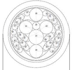
 PXD (DEPFET), Central Drift Chamber (CDC) PI barrel / PI Endcap TOP+A-RICH 5 de")
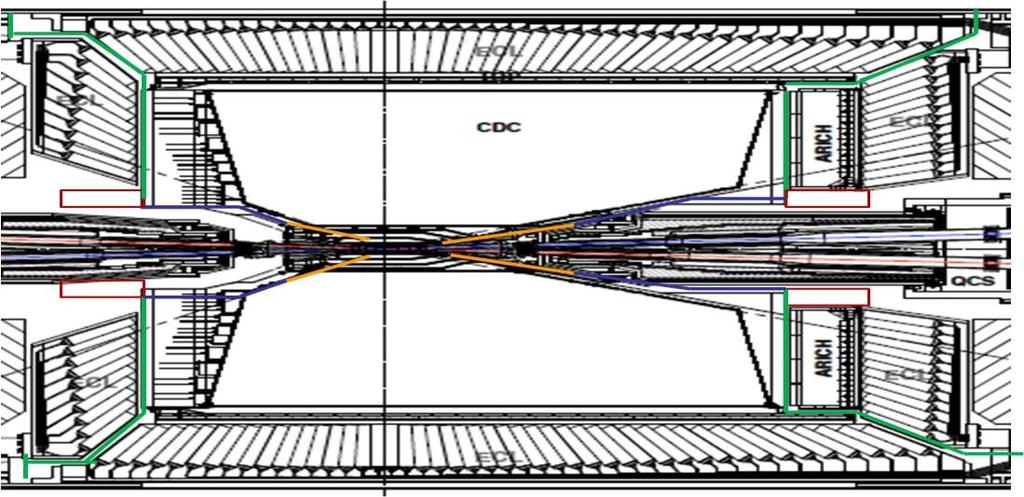
6 2. GND & EMC strategy CsI EM calorimeter (ECL) RPC μ & K L counter: scintillator + Si-PM (for end-caps) (eklm-bklm) Solenoid SVD (Silicon Vertex Detector) PXD (DEPFET), Central Drift Chamber (CDC) PI barrel / PI Endcap TOP+A-RICH 5 de 28
7 2. GND & EMC strategy The main goal of Grounding & EMC integration strategy is to ensure the correct performance of Belle II experiment. Ensure the compatibility in each sub-system Ensure the compatibility among units sub-systems It establishes a safety margin EMC integration strategy has three parts: Grounding issues Cabling issues EMC issues Compatibility Compatibility Compatibility SUB1 SUB2 6 de 28
8 3. Grounding What is a ground? It is a reference : Uniform reference voltage at any frequency It is a structure to bypass currents Fault (short circuits..) Noise Reasons for Grounding Safety Equipment protection Equipment performance Golden rule: Make the system safe and then make it work Several recommendations were made. 7 de 28
9 3.1 Grounding Topologies Most of the grounding topologies has been presented Multipoint ground Floating PS units (LV) It is time to define a common topology for all subdetectors First hot areas have arisen Grounded vs Floating (FEE) Performance vs Safety (HV) Safety issues have become a priority concern Belle II electrical safety requirements KEK electrical safety rules (Coordination) They may have an impact on the design 8 de 28


10 3.1 Grounding Topologies PXD Multipoint GND using cooling blocks LV floating power supply DC-DC converters Multipoint GND at DOCK box DOCK connected to CDC (detector structure) Isolated LV DC-DC Non Isolated HV Gnd via resistors FDAC Differential Transmi. SVD 9 de 28

11 3.1 Grounding Topologies Multipoint GND Isolated LV Non-isolated HV 100/200 ohms common ground at FEE LV shields connected locally ARICH TOP Plan to ground at the detector side support structure LV, HV, Bias, DAQ cables connected to the detector Signal processing done at the front-end board shielded. Pick-up noise not observed 10 de 28
 No connect: Mech.")
12 3.1 Grounding Topologies bklm Grounding topology Single-point at each detector module (multipoint) Grounding connections AC ground at detector, DC ground at readout crate; HV DC ground at power supply It is planned to use the same gnd scheme as for Belle. (good results) No connect: Mech.structure - FE board Connection: FE amp gnd frame Shield connected 1s 11 de 28 ECL


13 3.1 Grounding Topologies CDC It proposes an isolation ground philosophy. It required to be separated from Belle- II structure, BPID, SVD and others. Signal ground connected to: The backward end plate in the CDC Through the power modules in the electronics hut. High voltage ground may be disconnected from the forward end plate. Grounding topology still open Some test set-up are ready for noise measurements: They plan to study several ground topologies. 12 de 28 eklm
14 3.2 Grounding summary The sub-detectors have presented different gnd strategies Locally, floating, multipoint, A general grounding policy should be defined. Even in sub-detectors that are intrinsically immune to noise, grounding should be coordinated in order to avoid EM radiation to neighbors. Special attention should be paid to large floating system due to the creation of uncontrolled noise paths. A detailed definition of electrical schematics and grounding techniques may be used to start coordinating the installation of sub-systems These activities will be carried out by a group of people (Belle II) It is recommended to evaluate the grounding technique at prototype level before installation It will help to take corrective actions in advance 13 de 28
15 4. Cabling issues There are two elements that play an important role in the electromagnetic noise level of any experiment: Cables Racks They may cause many EMC problems: Cable radiation Cable susceptibility Malfunctions due to high electronics density The EMC effects of this type of elements may be decreased by design ( layout and connectivity) Some recommendations were presented They may be implemented wherever possible. 14 de 28


16 4. Cabling issues Cables and racks components of different EMC categories should be laid separately wherever possible 15 de 28
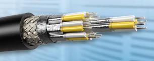
17 4.1 Sub-detector cabling The cable layout and power levels of each subdetector have been discussed during the meetings. There is a wide variability of different options Type of cable Some of them are new In some cases it is planned to use Belle I cables Power levels KV, V, Signal, power Common cable channels have been shown There are some areas that need to be analyzed in detail to avoid interference problems Some cables are shielded and others not at all 16 de 28


18 4.1 Sub-detector cabling PXD SVD 17 de 28


19 4.1 Sub-detector cabling CDC Definition of cable power levels +5.5, +3.8, +2.0, +1.5 ARICH 18 de 28


20 4.1 Sub-detector cabling layout levels Types Exit radially from the magnet to readout crates nearby on perimeter of magnet 12V, 5V, 6kV, -3.5kV Unshielded twist-n-flat signal cable, RG-59 HV cable eklm 19 de 28
21 4.2 Cabling summary The cable layout and power levels of each sub-detector have been partially presented Some areas are common to different sub-detectors and mix different types of cables Detail analysis is required Attention should be paid to cable shield as well as noise sources. Interference evaluation: Noise sources vs type of cable A collection of safety rules beyond the ampacity of the cables should be defined and communicated to all sub-detectors Noise & Transients fuse coordination, electronic protection, de-rating cable ampacity for cable bundles It is recommended to create a committee that reviews and enforces that the cable and wire layout complies with rules 20 de 28 Belle II and KEK members
22 5. EMC issues Analysis & tests to ensure the compatibility level among noise sources and victims have started This noise control is being tackled at two levels 21 de 28 Noise emissions analysis Noise emission test (conducted and radiated) Noise immunity analysis Signal circuit analysis It will help to define grounding topologies Noise Immunity test Evaluate grounding topologies Ensure the compatibility of the FEE Subsystem evaluation: Signal to noise quantification
23 5.1 EMC issues - Emissions One of the most important noise sources in Belle II are the power supplies. Several of them have been developed with DC-DC They have EM emissions Radiated Conducted Emissions The spectra content is very closely related to : Switching frequency - Topology Few khz up to MHz The emission level of the power supply has to be coordinated: Sub-detector level Experiment level 22 de 28


24 db A / m db A 5.1 EMC issues - Emissions CM DCDC5 DIF Steering ST4V PXD Frequency 60 Radiated - H de Frequency
25 5.2 EMC unit analysis: Noise immunity Are the PS noise emissions (or other) compatible with the FEE?? Do we have enough safety margin? Noise sources that deteriorate the FEE performance are: Intrinsic thermal noise EM contribution detector FEE PS - others n a (t) n th (t) n in (t) n ps (t) This noise defines the minimum signal level that the FEE can process Thermal noise dominant effect EMI contribution characterization important The characterization of EMI contributions may be carried out via : Modeling and simulation of system Immunity tests on prototypes The main goals of this EM characterization are: Evaluate grounding topologies Ensure the compatibility of the FEE Subsystem evaluation : Signal to noise quantification 24 de 28


26 5.2 EMC issues - Immunities ECL System Verification PXD bklm Signal circuit analysis 25 de 28
27 5.3 EMC summary Analysis and test to ensure the compatibility level among noise sources and victims has started. The noise control is tackled at two levels Noise emissions Noise immunities Some subsystems have presented EMC plans and tests but it is still necessary to prepare a detailed global plan. This plan will help to define sensitive frequencies that may interfere among sub-detectors Some of the immunity tests will be very useful for final grounding topology of each sub-detector Still under development 26 de 28
28 6. Future Plans Electrical safety rules for Belle II need to be clarified. An overall "Belle II" grounding diagram and more detailed EMC plan should be prepared. Each sub-detector system will provide a very detailed /grounding overview (simplified schematic) & EMC plans It will be necessary to establish a grounding and EMC responsible at KEK in order to follow the indications. This person may act now as a link person Belle II - KEK It is planned to follow up all plans in order to define global aspects of the Belle II integration Cabling (Short term) Grounding (Short-medium term) EMC (long term) 27 de 28
29 7. Conclusions A general overview of the status and plans of the grounding and EMC issues has been presented EMC & grounding activities started one and a half years ago All sub-detectors have been involved Several meetings were held On July, we had a GND & EMC review at VPI, USA This review has produced a significant step forward Groundings configuration Cables layout EMC issues This is only the beginning of a long work. 28 de 28
EMC review for Belle II (Grounding & shielding plans) PXD DEPFET system
 PXD DEPFET system") EMC review for Belle II (Grounding & shielding plans) PXD DEPFET system Outline 1. Introduction 2. Grounding strategy Implementation aspects 3. Noise emission issues Test plans 4. Noise immunity issues
EMC review for Belle II (Grounding & shielding plans) PXD DEPFET system Outline 1. Introduction 2. Grounding strategy Implementation aspects 3. Noise emission issues Test plans 4. Noise immunity issues
Detector noise susceptibility issues for the future generation of High Energy Physics Experiments
 SLAC-PUB-14771 Detector noise susceptibility issues for the future generation of High Energy Physics Experiments F. Arteche a, C. Esteban a, M. Iglesias a, C. Rivetta b, F.J. Arcega c a Instituto Tecnológico
EMC Immunity studies for front-end electronics in high-energy physics experiments
 EMC Immunity studies for front-end electronics in high-energy physics experiments F. Arteche*, C. Rivetta**, *CERN,1211 Geneve 23 Switzerland, **FERMILAB, P.O Box 0 MS341, Batavia IL 510 USA. e-mail: fernando.arteche@cern.ch,
Verifying Simulation Results with Measurements. Scott Piper General Motors
 Verifying Simulation Results with Measurements Scott Piper General Motors EM Simulation Software Can be easy to justify the purchase of software packages even costing tens of thousands of dollars Upper
Overview of the ATLAS Electromagnetic Compatibility Policy
 Overview of the ATLAS Electromagnetic Compatibility Policy G. Blanchot CERN, CH-1211 Geneva 23, Switzerland Georges.Blanchot@cern.ch Abstract The electromagnetic compatibility of ATLAS electronic equipments
Tracking Detectors for Belle II. Tomoko Iwashita(Kavli IPMU (WPI)) Beauty 2014
) Beauty 2014") Tracking Detectors for Belle II Tomoko Iwashita(Kavli IPMU (WPI)) Beauty 2014 1 Introduction Belle II experiment is upgrade from Belle Target luminosity : 8 10 35 cm -2 s -1 Target physics : New physics
Tracking Detectors for Belle II Tomoko Iwashita(Kavli IPMU (WPI)) Beauty 2014 1 Introduction Belle II experiment is upgrade from Belle Target luminosity : 8 10 35 cm -2 s -1 Target physics : New physics
Lecture 11. Complex Detector Systems
 Lecture 11 Complex Detector Systems 1 Dates 14.10. Vorlesung 1 T.Stockmanns 1.10. Vorlesung J.Ritman 8.10. Vorlesung 3 J.Ritman 04.11. Vorlesung 4 J.Ritman 11.11. Vorlesung 5 J.Ritman 18.11. Vorlesung
EMI Filter Design and Stability Assessment of DC Voltage Distribution based on Switching Converters.
 EMI Filter Design and Stability Assessment of DC Voltage Distribution based on Switching Converters. F. Arteche 1, B. Allongue 1, F. Szoncso 1, C. Rivetta 2 1 CERN, 1211 Geneva 23, Switzerland Fernando.Arteche@cern.ch
EMC Phenomena in HEP Detectors: Prevention and Cost Savings
 EMC Phenomena in HEP Detectors: Prevention and Cost Savings F. Arteche Imperial College, University of London CERN, CH-1211 Geneve 23, Switzerland C. Rivetta SLAC, Stanford, CA 94025, USA SLAC-PUB-11884
Q1-2 Q3-4 Q1-2 Q3-4 Q1-2 Q3-4 Q1-2 Q3-4 Q1-2 Q3-4 Q1-2 Q3-4 Q1-2 Q3-4 Q1-2 Q3-4 Q1-2 Q3-4 Q1-2 Q3-4. Final design and pre-production.
 high-granularity sfcal Performance simulation, option selection and R&D Figure 41. Overview of the time-line and milestones for the implementation of the high-granularity sfcal. tooling and cryostat modification,
Immunity Testing for the CE Mark
 Immunity Testing for the CE Mark Summary The European Union (EU) currently has 25 member countries with 2 additional countries to be added in 2007. The total population at that time will be nearly a half
Particle identification at Belle-II
 Particle identification at Belle-II Matthew Barrett University of Hawaiʻi at Mānoa University of Oxford seminar Outline The B factories Belle II and superkekb The TOP subdetector The Belle II sub-detectors
Electromagnetic and Radio Frequency Interference (EMI/RFI) Considerations For Nuclear Power Plant Upgrades
 Considerations For Nuclear Power Plant Upgrades") Electromagnetic and Radio Frequency Interference (EMI/RFI) Considerations For Nuclear Power Plant Upgrades November 9, 2016 Presented to: Presented by: Chad Kiger EMC Engineering Manager ckiger@ams-corp.com
Electromagnetic and Radio Frequency Interference (EMI/RFI) Considerations For Nuclear Power Plant Upgrades November 9, 2016 Presented to: Presented by: Chad Kiger EMC Engineering Manager ckiger@ams-corp.com
10 Safety earthing/grounding does not help EMC at RF
 1of 6 series Webinar #3 of 3, August 28, 2013 Grounding, Immunity, Overviews of Emissions and Immunity, and Crosstalk Contents of Webinar #3 Topics 1 through 9 were covered by the previous two webinars
Unleash SiC MOSFETs Extract the Best Performance
 Unleash SiC MOSFETs Extract the Best Performance Xuning Zhang, Gin Sheh, Levi Gant and Sujit Banerjee Monolith Semiconductor Inc. 1 Outline SiC devices performance advantages Accurate test & measurement
Common Impedance Coupling Effect on Video and Audio Circuitry. Prof. Bogdan Adamczyk Grand Valley State University
 Common Impedance Coupling Effect on Video and Audio Circuitry Prof. Bogdan Adamczyk rand Valley State University Outline 1. Signal ground (signal return path) 2. Objectives of grounding 3. Single- vs.
CHAPTER 6 EMI EMC MEASUREMENTS AND STANDARDS FOR TRACKED VEHICLES (MIL APPLICATION)
") 147 CHAPTER 6 EMI EMC MEASUREMENTS AND STANDARDS FOR TRACKED VEHICLES (MIL APPLICATION) 6.1 INTRODUCTION The electrical and electronic devices, circuits and systems are capable of emitting the electromagnetic
147 CHAPTER 6 EMI EMC MEASUREMENTS AND STANDARDS FOR TRACKED VEHICLES (MIL APPLICATION) 6.1 INTRODUCTION The electrical and electronic devices, circuits and systems are capable of emitting the electromagnetic
Electromagnetic Compatibility
 Electromagnetic Compatibility Introduction to EMC International Standards Measurement Setups Emissions Applications for Switch-Mode Power Supplies Filters 1 What is EMC? A system is electromagnetic compatible
Grounding, Shielding and Power Distribution in LHCb
 Grounding, Shielding and Power Distribution in LHCb LHCB Technical Note Issue: released Revision: 6 Reference: LHCb 2004-039 Created: Jan. 2001 Last modified: May 2004 Prepared By: Vincent Bobillier, Jorgen
The Detector at the CEPC: Calorimeters
 The Detector at the CEPC: Calorimeters Tao Hu (IHEP) and Haijun Yang (SJTU) (on behalf of the CEPC-SppC Study Group) IHEP, Beijing, March 11, 2015 Introduction Calorimeters Outline ECAL with Silicon and
R & D for Aerogel RICH
 1 R & D for Aerogel RICH Ichiro Adachi KEK Proto-Collaboration Meeting March 20, 2008 2 1 st Cherenkov Image detected by 3 hybrid avalanche photon detectors from a beam test About 3:00 AM TODAY Clear image
The 1st Result of Global Commissioning of the ATALS Endcap Muon Trigger System in ATLAS Cavern
 The 1st Result of Global Commissioning of the ATALS Endcap Muon Trigger System in ATLAS Cavern Takuya SUGIMOTO (Nagoya University) On behalf of TGC Group ~ Contents ~ 1. ATLAS Level1 Trigger 2. Endcap
EMC of Power Converters
 Alain CHAROY - (0033) 4 76 49 76 76 - a.charoy@aemc.fr EMC EMC of Power Converters Friday 9 May 2014 Electromagnetism is just electricity Converters are particularly concerned with EMC: Conducted disturbances
BaBar and PEP II. Physics
 BaBar and PEP II BaBar SVT DCH DIRC ECAL IFR Trigger Carsten Hast LAL Orsay December 8th 2000 Physics Main Goal: CP Violation sin2β,sin2α PEP II Performance Backgrounds December 8th 2000 Carsten Hast PEP
Relationship Between Signal Integrity and EMC
 Relationship Between Signal Integrity and EMC Presented by Hasnain Syed Solectron USA, Inc. RTP, North Carolina Email: HasnainSyed@solectron.com 06/05/2007 Hasnain Syed 1 What is Signal Integrity (SI)?
Topologies for Optimizing Efficiency, EMC and Time to Market
 LED Power Supply Topologies Topologies for Optimizing Efficiency, EMC and Time to Market El. Ing. Tobias Hofer studied electrical engineering at the ZBW St. Gallen. He has been working for Negal Engineering
Determining The Size Of Cabinet Apertures For Effectively Mitigating Radiated Emissions. By David Norte Thursday, April 7 th, 2005
 The EMC, Signal And Power Integrity Institute Presents Determining The Size Of Cabinet Apertures For Effectively Mitigating Radiated Emissions By David Norte Thursday, April 7 th, 2005 1 Motivation For
Design for Guaranteed EMC Compliance
 Clemson Vehicular Electronics Laboratory Reliable Automotive Electronics Automotive EMC Workshop April 29, 2013 Design for Guaranteed EMC Compliance Todd Hubing Clemson University EMC Requirements and
75W Constant Current (700mA) LED Driver
 LED Driver") 75W Constant Current (700mA) LED Driver IZC070-075A-9267C-SA Product Overview The IZC070-075A-9267C-SA operates from a 90-305 Vac input range. This unit will provide up to 700mA of output current and a
75W Constant Current (700mA) LED Driver IZC070-075A-9267C-SA Product Overview The IZC070-075A-9267C-SA operates from a 90-305 Vac input range. This unit will provide up to 700mA of output current and a
Motivation Overview Grounding & Shielding L1 Trigger System Diagrams Front-End Electronics Modules
 F.J. Barbosa, Jlab 1. 2. 3. 4. 5. 6. 7. 8. 9. Motivation Overview Grounding & Shielding L1 Trigger System Diagrams Front-End Electronics Modules Safety Summary 1 1. Motivation Hall D will begin operations
Differential Amplifiers
 Differential Amplifiers Benefits of Differential Signal Processing The Benefits Become Apparent when Trying to get the Most Speed and/or Resolution out of a Design Avoid Grounding/Return Noise Problems
EMC Testing to Achieve Functional Safety
 Another EMC resource from EMC Standards EMC Testing to Achieve Functional Safety Helping you solve your EMC problems 9 Bracken View, Brocton, Stafford ST17 0TF T:+44 (0) 1785 660247 E:info@emcstandards.co.uk
SLAC-LLNL ILC Damping Ring Kicker High Availability Modulator R&D Program
 SLAC-LLNL ILC Damping Ring Kicker High Availability Modulator R&D Program Craig Burkhart for the SLAC-LLNL Team: E. Cook (LLNL) A. Krasnykh, R. Larsen, T. Tang (SLAC) Slide Overview Americas SLAC-LLNL
An RS485 bus is used for command, monitoring and diagnostic information that can be supplied to a system controller.
 The TCP3500 series is an AC-DC converter with adjustable DC output and universal 3-phase AC input. Conduction cooling (No Fans) makes this power supply series suitable for a wide variety of Industrial
Applications of 3D Electromagnetic Modeling in Magnetic Recording: ESD and Signal Integrity
 Applications of 3D Electromagnetic Modeling in Magnetic Recording: ESD and Signal Integrity CST NORTH AMERICAN USERS FORUM John Contreras 1 and Al Wallash 2 Hitachi Global Storage Technologies 1. San Jose
TECHNICAL REQUIREMENTS FOR ELECTROMAGNETIC DISTURBANCES EMITTED FROM LIGHTING EQUIPMENT INSTALLED IN TELECOMMUNICATION CENTERS
 TR550004 TECHNICAL REQUIREMENTS FOR ELECTROMAGNETIC DISTURBANCES EMITTED FROM LIGHTING EQUIPMENT INSTALLED IN TELECOMMUNICATION CENTERS TR NO. 174001 EDITION 2.1 September 3 rd, 2018 Nippon Telegraph and
IEEE RTPGE Automotive Datalinks over Twisted Quad Cabling
 Automotive Datalinks over Twisted Quad Cabling T. Müller, G. Armbrecht, S. Kunz Rosenberger Hochfrequenztechnik GmbH & Co. KG Outline Automotive Datalinks over Twisted Quad Cabling Twisted Quad fundamentals
CALICE AHCAL overview
 International Workshop on the High Energy Circular Electron-Positron Collider in 2018 CALICE AHCAL overview Yong Liu (IHEP), on behalf of the CALICE collaboration Nov. 13, 2018 CALICE-AHCAL Progress, CEPC
Facility Grounding & Bonding Based on the EMC/PI/SI Model for a High Speed PCB/Cabinet
 Facility Grounding & Bonding Based on the EMC/PI/SI Model for a High Speed PCB/Cabinet and: SILICON LABS AN203 PRINTED CIRCUIT BOARD DESIGN NOTES www.silabs.com William Bush (wbush@ieee.org) Industry Consultant
For the electronic measurement of voltage: DC, AC, pulsed..., with galvanic isolation between the primary and the secondary circuit.
 Voltage transducer V PN = 1 V Ref: DV 1/SP For the electronic measurement of voltage: DC, AC, pulsed..., with galvanic isolation between the primary and the secondary circuit. Features Bipolar and isolated
Semiconductor Detector Systems
 Semiconductor Detector Systems Helmuth Spieler Physics Division, Lawrence Berkeley National Laboratory OXFORD UNIVERSITY PRESS ix CONTENTS 1 Detector systems overview 1 1.1 Sensor 2 1.2 Preamplifier 3
Pixel hybrid photon detectors
 Pixel hybrid photon detectors for the LHCb-RICH system Ken Wyllie On behalf of the LHCb-RICH group CERN, Geneva, Switzerland 1 Outline of the talk Introduction The LHCb detector The RICH 2 counter Overall
Introduction to Electromagnetic Compatibility
 Introduction to Electromagnetic Compatibility Second Edition CLAYTON R. PAUL Department of Electrical and Computer Engineering, School of Engineering, Mercer University, Macon, Georgia and Emeritus Professor
EMC Simulation of Consumer Electronic Devices
 of Consumer Electronic Devices By Andreas Barchanski Describing a workflow for the EMC simulation of a wireless router, using techniques that can be applied to a wide range of consumer electronic devices.
2620 Modular Measurement and Control System
 European Union (EU) Council Directive 89/336/EEC Electromagnetic Compatibility (EMC) Test Report 2620 Modular Measurement and Control System Sensoray March 31, 2006 April 4, 2006 Tests Conducted by: ElectroMagnetic
EMI AND BEL MAGNETIC ICM
 EMI AND BEL MAGNETIC ICM ABSTRACT Electromagnetic interference (EMI) in a local area network (LAN) system is a common problem that every LAN system designer faces, and it is a growing problem because the
Harmonizing the ANSI-C12.1(2008) EMC Tests. Harmonizing the ANSI-C12.1(2008) EMC Tests
 EMC Tests. Harmonizing the ANSI-C12.1(2008) EMC Tests") Harmonizing the ANSI-C12.1(2008) EMC Tests Subcommittee 1 (Emissions) Subcommittee 5 (Immunity) Joint Task Force on C12.1 June 17, 2013 1 The Accredited Standards Committee C63 presents Harmonizing the
Harmonizing the ANSI-C12.1(2008) EMC Tests Subcommittee 1 (Emissions) Subcommittee 5 (Immunity) Joint Task Force on C12.1 June 17, 2013 1 The Accredited Standards Committee C63 presents Harmonizing the
3.7 Grounding Design for EAST Superconducting Tokamak
 3.7 Design for EAST Superconducting Tokamak LIU Zhengzhi 3.7.1 Introduction system is a relevant part of the layout of Tokamak. It is important and indispensable for the system reliability and safety on
Class-D Audio Power Amplifiers: PCB Layout For Audio Quality, EMC & Thermal Success (Home Entertainment Devices)
") Class-D Audio Power Amplifiers: PCB Layout For Audio Quality, EMC & Thermal Success (Home Entertainment Devices) Stephen Crump http://e2e.ti.com Audio Power Amplifier Applications Audio and Imaging Products
Class-D Audio Power Amplifiers: PCB Layout For Audio Quality, EMC & Thermal Success (Home Entertainment Devices) Stephen Crump http://e2e.ti.com Audio Power Amplifier Applications Audio and Imaging Products
Status of the LHCb Experiment
 Status of the LHCb Experiment Werner Witzeling CERN, Geneva, Switzerland On behalf of the LHCb Collaboration Introduction The LHCb experiment aims to investigate CP violation in the B meson decays at LHC
Common myths, fallacies and misconceptions in Electromagnetic Compatibility and their correction.
 Common myths, fallacies and misconceptions in Electromagnetic Compatibility and their correction. D. A. Weston EMC Consulting Inc 15-3-2013 1) First topic an introduction These are some of the commonly
Guidance and Declaration - Electromagnetic Compatibility (EMC) for the Delfi PTS ii Portable Tourniquet System
 for the Delfi PTS ii Portable Tourniquet System") Guidance and Declaration - Electromagnetic Compatibility (EMC) for the Delfi TS ii ortable Tourniquet System Guidance and manufacturer s declaration electromagnetic emissions The TS ii ortable Tourniquet
Guidance and Declaration - Electromagnetic Compatibility (EMC) for the Delfi TS ii ortable Tourniquet System Guidance and manufacturer s declaration electromagnetic emissions The TS ii ortable Tourniquet
INTRODUCTION TO CONDUCTED EMISSION
 IEEE EMC Chapter - Hong Kong Section EMC Seminar Series - All about EMC Testing and Measurement Seminar 2 INTRODUCTION TO CONDUCTED EMISSION By Duncan FUNG 18 April 2015 TOPICS TO BE COVERED Background
NI 2865A 0.3 A Matrix Cards for NI SwitchBlock
 SPECIFICATIONS NI 2865A 0.3 A Matrix Cards for NI SwitchBlock This document lists specifications for the NI 2865A matrix relay cards. All specifications are subject to change without notice. Visit ni.com/manuals
EMC Near-field Probes + Wideband Amplifier
 1 Introduction The H20, H10, H5 and E5 are magnetic field (H) and electric field (E) probes for radiated emissions EMC precompliance measurements. The probes are used in the near field of sources of electromagnetic
50W Constant Current (700mA) Dimming LED Driver
 Dimming LED Driver") 50W Constant Current (700mA) Dimming LED Driver IZC070-050A-9267C-SA Product Overview The IZC070-050A-9267C-SA operate from a 90-305 Vac input range. This unit will provide up to a 700mA of output current
50W Constant Current (700mA) Dimming LED Driver IZC070-050A-9267C-SA Product Overview The IZC070-050A-9267C-SA operate from a 90-305 Vac input range. This unit will provide up to a 700mA of output current
Test of Signal Transmission for a GERDA string
 Test of Signal Transmission for a GERDA string Béla Majorovits Test of Signal Transmission for a GERDA string 1 GERDA Signal Transmission Schematically: Köln type Preamp procured by DSG Habia Teflon coated
For the electronic measurement of voltage: DC, AC, pulsed..., with galvanic separation between the primary and the secondary circuit.
 Voltage transducer DV V PN = V For the electronic measurement of voltage: DC, AC, pulsed..., with galvanic separation between the primary and the secondary circuit. Features Applications Bipolar and insulated
11 Myths of EMI/EMC ORBEL.COM. Exploring common misconceptions and clarifying them. MYTH #1: EMI/EMC is black magic.
 11 Myths of EMI/EMC Exploring common misconceptions and clarifying them By Ed Nakauchi, Technical Consultant, Orbel Corporation What is a myth? A myth is defined as a popular belief or tradition that has
Plans for RPC DHCAL Prototype. David Underwood Argonne National Laboratory
 Plans for RPC DHCAL Prototype David Underwood Argonne National Laboratory Linear Collider Meeting, SLAC 7-10 January 2004 Outline Collaborators Goals Motivation Mechanical Structure Chamber Description
Typical Efficiency (1) 350 ma 90 ~ 305 Vac 428 Vdc 150 W 93.5% EUC-150S035DT
 350 ma 90 ~ 305 Vac 428 Vdc 150 W 93.5% EUC-150S035DT") Features Ultra High Efficiency (Up to 93.5%) Active Power Factor Correction (0.99 Typical) Constant Current Output Lightning Protection AllRound Protection: SCP, OTP, OVP Waterproof (IP67) Comply With
Features Ultra High Efficiency (Up to 93.5%) Active Power Factor Correction (0.99 Typical) Constant Current Output Lightning Protection AllRound Protection: SCP, OTP, OVP Waterproof (IP67) Comply With
Designing external cabling for low EMI radiation A similar article was published in the December, 2004 issue of Planet Analog.
 HFTA-13.0 Rev.2; 05/08 Designing external cabling for low EMI radiation A similar article was published in the December, 2004 issue of Planet Analog. AVAILABLE Designing external cabling for low EMI radiation
Spectrometer cavern background
 ATLAS ATLAS Muon Muon Spectrometer Spectrometer cavern cavern background background LPCC Simulation Workshop 19 March 2014 Jochen Meyer (CERN) for the ATLAS Collaboration Outline ATLAS Muon Spectrometer
A Comparison Between MIL-STD and Commercial EMC Requirements Part 2. By Vincent W. Greb President, EMC Integrity, Inc.
 A Comparison Between MIL-STD and Commercial EMC Requirements Part 2 By Vincent W. Greb President, EMC Integrity, Inc. OVERVIEW Compare and contrast military (i.e., MIL-STD) and commercial EMC immunity
Electromagnetic Compatibility of Power Converters
 Published by CERN in the Proceedings of the CAS-CERN Accelerator School: Power Converters, Baden, Switzerland, 7 14 May 2014, edited by R. Bailey, CERN-2015-003 (CERN, Geneva, 2015) Electromagnetic Compatibility
Reminder on the TOB electronics architecture Test of the first SS rod prototype
 Reminder on the TOB electronics architecture Test of the first SS rod prototype Results Further steps Duccio Abbaneo CMS Electronics Week November 2002 1 The rod CCU Module SC out LV out SC in LV in LV
Bulk Current Injection instead of Radiated immunity testing, in the range from 1 MHz upto 1 GHz: Measuring results
 Immunity Testing: radiated immunity 41 Bulk Current Injection instead of Radiated immunity testing, in the range from 1 MHz upto 1 GHz: Measuring results Immunity Testing: radiated immunity 42 Bulk Current
Contents. The AMADEUS experiment at the DAFNE collider. The AMADEUS trigger. SiPM characterization and lab tests
 Contents The AMADEUS experiment at the DAFNE collider The AMADEUS trigger SiPM characterization and lab tests First trigger prototype; tests at the DAFNE beam Second prototype and tests at PSI beam Conclusions
Modeling and Simulation of Powertrains for Electric and Hybrid Vehicles
 Modeling and Simulation of Powertrains for Electric and Hybrid Vehicles Dr. Marco KLINGLER PSA Peugeot Citroën Vélizy-Villacoublay, FRANCE marco.klingler@mpsa.com FR-AM-5 Background The automotive context
Alternative Coupling Method for Immunity Testing of Power Grid Protection Equipment
 Alternative Coupling Method for Immunity Testing of Power Grid Protection Equipment Christian Suttner*, Stefan Tenbohlen Institute of Power Transmission and High Voltage Technology (IEH), University of
Overview of EMC Regulations and Testing. Prof. Tzong-Lin Wu Department of Electrical Engineering National Taiwan University
 Overview of EMC Regulations and Testing Prof. Tzong-Lin Wu Department of Electrical Engineering National Taiwan University What is EMC Electro-Magnetic Compatibility ( 電磁相容 ) EMC EMI (Interference) Conducted
For the electronic measurement of voltage: DC, AC, pulsed..., with galvanic isolation between the primary and the secondary circuit.
 Voltage transducer V PN = 4 V Ref: DV 4/SP4 For the electronic measurement of voltage: DC, AC, pulsed..., with galvanic isolation between the primary and the secondary circuit. Features Bipolar and isolated
Biological Safety. Electromagnetic Compatibility (EMC) Observe the following precautions related to biological safety.
 Observe the following precautions related to biological safety.") Biological Safety Observe the following precautions related to biological safety. WARNING: Non-medical (commercial) grade peripheral monitors have not been verified or validated by SonoSite as being suitable
Biological Safety Observe the following precautions related to biological safety. WARNING: Non-medical (commercial) grade peripheral monitors have not been verified or validated by SonoSite as being suitable
Solving Electromagnetic Interference (EMI) with Ferrites
 with Ferrites") Solving Electromagnetic Interference (EMI) with Ferrites What are ferrites? How do ferrites help Suppress EMI? How to chose proper ferrite and component Material Characteristics Material and Core Selection
Solving Electromagnetic Interference (EMI) with Ferrites What are ferrites? How do ferrites help Suppress EMI? How to chose proper ferrite and component Material Characteristics Material and Core Selection
Max. Output Power. Efficiency (1) 110Vac 220Vac
 110Vac 220Vac") LED Driver EUV150SxxxST 20100531 H Features Ultra High (Up to ) High Power Factor (0.99 Typical) 150 W Continuous Power Lightning Protection AllRound Protection: OVP, OCP, SCP, OTP Waterproof (IP67) Comply
LED Driver EUV150SxxxST 20100531 H Features Ultra High (Up to ) High Power Factor (0.99 Typical) 150 W Continuous Power Lightning Protection AllRound Protection: OVP, OCP, SCP, OTP Waterproof (IP67) Comply
Max. Output Power. Typical Efficiency (2) 24 Vdc 176 ~ 305 Vac 0~20.83 A 500 W 93.5% EBV-500S024SV
 24 Vdc 176 ~ 305 Vac 0~20.83 A 500 W 93.5% EBV-500S024SV") EBV500SxxxSV Features Ultra High Efficiency (Up to 94.5%) Constant Voltage Output Input surge protection: 4kV lineline, 6kV lineearth AllAround Protection: SCP, OTP, OVP, OCP Waterproof (IP67) SELV Output
EBV500SxxxSV Features Ultra High Efficiency (Up to 94.5%) Constant Voltage Output Input surge protection: 4kV lineline, 6kV lineearth AllAround Protection: SCP, OTP, OVP, OCP Waterproof (IP67) SELV Output
Development and Test of a Demonstrator for a First-Level Muon Trigger based on the Precision Drift Tube Chambers for ATLAS at HL-LHC
 Development and Test of a Demonstrator for a First-Level Muon Trigger based on the Precision Drift Tube Chambers for ATLAS at HL-LHC K. Schmidt-Sommerfeld Max-Planck-Institut für Physik, München K. Schmidt-Sommerfeld,
Common myths, fallacies and misconceptions in Electromagnetic Compatibility and their correction.
 Common myths, fallacies and misconceptions in Electromagnetic Compatibility and their correction. D. A. Weston EMC Consulting Inc 22-3-2010 These are some of the commonly held beliefs about EMC which are
CHAPTER 2 EQUIVALENT CIRCUIT MODELING OF CONDUCTED EMI BASED ON NOISE SOURCES AND IMPEDANCES
 29 CHAPTER 2 EQUIVALENT CIRCUIT MODELING OF CONDUCTED EMI BASED ON NOISE SOURCES AND IMPEDANCES A simple equivalent circuit modeling approach to describe Conducted EMI coupling system for the SPC is described
Industrial PSU with universal input voltage range ( VAC line to line) and configurable output voltage. North America
 and configurable output voltage. North America") World-Wide 3-phase Input Voltage Range (nom. 200 Vrms to 480 Vrms), PF > 0.94 High Power Density 16 W/in 3 94% Typical Efficiency Parallel Operation up to 16 Units (50.4 kw) Cold-Plate Cooling System -25
World-Wide 3-phase Input Voltage Range (nom. 200 Vrms to 480 Vrms), PF > 0.94 High Power Density 16 W/in 3 94% Typical Efficiency Parallel Operation up to 16 Units (50.4 kw) Cold-Plate Cooling System -25
One-day Conference 18 March Power Supply, EMC and Signalling, in Railway Systems
 One-day Conference 18 March 2017 Power Supply, EMC and Signalling, in Railway Systems EMC Management and Related Technical Aspects in Railway Systems By Dr Peter S W LEUNG http://www.ee.cityu.edu.hk/~pswleung/
Intra-system EMI hardening for increased machine reliability. Ray Brett.
 Intra-system EMI hardening for increased machine reliability Ray Brett ray.brett@philips.com Assembleon Pick & Place SMT equipment Assembleon SIEMENS VDO AUTOMOTIVE 2 Contents Trends in Product Creation
Production of HPDs for the LHCb RICH Detectors
 Production of HPDs for the LHCb RICH Detectors LHCb RICH Detectors Hybrid Photon Detector Production Photo Detector Test Facilities Test Results Conclusions IEEE Nuclear Science Symposium Wyndham, 24 th
Seminar. BELLE II Particle Identification Detector and readout system. Andrej Seljak advisor: Prof. Samo Korpar October 2010
 Seminar BELLE II Particle Identification Detector and readout system Andrej Seljak advisor: Prof. Samo Korpar October 2010 Outline Motivation BELLE experiment and future upgrade plans RICH proximity focusing
Balanced Constant Current Excitation for RTD Sensor Measurements
 Balanced Constant Current Excitation for RTD Sensor Measurements Douglas R. Firth Alan R. Szary Precision Filters, Inc. Ithaca, New York (607) 277-3550 1 Balanced Constant Current Excitation for RTD Sensor
SELECTION GUIDE. Nominal Input Voltage Output Voltage. Output Current
 www.murata-ps.com SELECTION GUIDE Order Code Nominal Input Voltage Output Current Input Current at Rated Load Load Regulation (Typ) Load Regulation (Max) Ripple & Noise (Typ) 1 Ripple & Noise (Max) 1 Efficiency
Overall Design Considerations for a Detector System at HIEPA
 Overall Design Considerations for a Detector System at HIEPA plus more specific considerations for tracking subdetectors Jianbei Liu For the USTC HIEPA detector team State Key Laboratory of Particle Detection
Max. Output Power. Efficiency (1) 110Vac 220Vac
 110Vac 220Vac") Features High (Up to 92%) Active Power Factor Correction (0.99 Typical) Constant Current Lightning Protection AllRound Protection: OVP, SCP, OTP Waterproof (IP67) Comply With UL8750 & EN61347 Safety Regulations
Features High (Up to 92%) Active Power Factor Correction (0.99 Typical) Constant Current Lightning Protection AllRound Protection: OVP, SCP, OTP Waterproof (IP67) Comply With UL8750 & EN61347 Safety Regulations
QPI-AN1 GENERAL APPLICATION NOTE QPI FAMILY BUS SUPPLY QPI CONVERTER
 QPI-AN1 GENERAL APPLICATION NOTE QPI FAMILY EMI control is a complex design task that is highly dependent on many design elements. Like passive filters, active filters for conducted noise require careful
A Prototype Amplifier-Discriminator Chip for the GLAST Silicon-Strip Tracker
 A Prototype Amplifier-Discriminator Chip for the GLAST Silicon-Strip Tracker Robert P. Johnson Pavel Poplevin Hartmut Sadrozinski Ned Spencer Santa Cruz Institute for Particle Physics The GLAST Project
MER1 Series 1kVDC Isolated 1W Single Output DC/DC Converters
 www.murata-ps.com MER1 Series SELECTION GUIDE Order Code Nominal Input Voltage Output Voltage Output Current Input Current at Rated Load Load Regulation (Typ) Load Regulation (Max) Ripple & Noise (Typ)
PC Krause and Associates, Inc.
 Common-mode challenges in high-frequency switching converters 14 NOV 2016 Nicholas Benavides, Ph.D. (Sr. Lead Engineer) 3000 Kent Ave., Suite C1-100 West Lafayette, IN 47906 (765) 464-8997 (Office) (765)
Designing Your EMI Filter
 The Engineer s Guide to Designing Your EMI Filter TABLE OF CONTENTS Introduction Filter Classifications Why Do We Need EMI Filters Filter Configurations 2 2 3 3 How to Determine Which Configuration to
EMC output filter recommendations for MA120XX(P)
") EMC output filter recommendations for MA120XX(P) About this document Scope and purpose This document provides EMC output filter recommendations that are tailored to the Merus Audio s MA12040, MA12040P,
EMC output filter recommendations for MA120XX(P) About this document Scope and purpose This document provides EMC output filter recommendations that are tailored to the Merus Audio s MA12040, MA12040P,
ITk silicon strips detector test beam at DESY
 ITk silicon strips detector test beam at DESY Lucrezia Stella Bruni Nikhef Nikhef ATLAS outing 29/05/2015 L. S. Bruni - Nikhef 1 / 11 Qualification task I Participation at the ITk silicon strip test beams
HEC-30/35LTA-33TDAA Rev A
 A. Features High Efficiency (Up to 86%). Active Power Factor Correction (Typical 0.95). Isolation Class II All-Round Protection: OVP/SCP/OTP/OPP. Fully isolated metal case with IP20 and dry location. 1-10V,
HEC-35LTA-XXTSAA Rev A
 A. Features High Efficiency (Up to 87%). Active Power Factor Correction (Typical 0.95). Isolation Class II. All-Round Protection: OVP/SCP/OTP/OPP. Fully isolated plastic case with IP20 and dry location.
FLTR100V10 Filter Module 75 Vdc Input Maximum, 10 A Maximum
 GE Critical Power FLTR100V10 Filter Module 75 Vdc Input Maximum, 10 A Maximum RoHS Compliant The FLTR100V10 Filter Module is designed to reduce the conducted common-mode and differential-mode noise on
How EMxpert Diagnoses Board-Level EMC Design Issues
 Application Report EMxpert July 2011 - Cédric Caudron How EMxpert Diagnoses Board-Level EMC Design Issues ABSTRACT EMxpert provides board-level design teams with world-leading fast magnetic very-near-field
Chapter 12 Digital Circuit Radiation. Electromagnetic Compatibility Engineering. by Henry W. Ott
 Chapter 12 Digital Circuit Radiation Electromagnetic Compatibility Engineering by Henry W. Ott Forward Emission control should be treated as a design problem from the start, it should receive the necessary