Timer A (0 and 1) and PWM EE3376
|
|
|
- Tabitha Sophia Garrison
- 5 years ago
- Views:
Transcription
1 Timer A (0 and 1) and PWM EE3376
2 General Peripheral Programming Model l l l l Each peripheral has a range of addresses in the memory map peripheral has base address (i.e. 0x00A0) each register used in the peripheral has an offset from the base some registers are for control l bits to enable the peripheral l bits to configure specific modes of operation l bits to determine level of clock division some registers are for status which is generally read-only l error conditions are represented with a bit in status register l completion status some registers are for data l data to be transmitted is written to data registers l data received can be read from data registers l data measured (i.e. ADC) can be read from data registers
3 Pulse Width Modulation l l l l Most commonly used for motor control switching mode for efficiency with transistor drive circuit One time configuration stand alone operation Pulse Width Modulation like a poor man s version of Digital to Analog Converter l take average value of square wave with variable duty cycle l low power output must buffer with driving circuit for high power applications (motors, etc) l can change analog value, but much slower than D/A Generates a square wave control of frequency control of duty cycle control of polarity - starts high, ends low OR starts low, ends high control of alignment left vs. center 8 independent channels on Port P (P for PWM)
4 Pulse Width Modulation 50% 75% 25% 10%
5 Pulse Width Modulation 50% selected clock counter value duty cycle period PWM frequency = F sc / (period) = 100KHz / 10 = 10 KHz PWM duty cycle = ((period duty cycle) / (period)) * 100% = ((10 5) / 10) * 100% = 50%
6 PWM Simple Design Example write to duty cycle duty cycle 8 bit compare = clksel 8 bit counter load r latch s output write to period 8 bit compare period =
7 Functions of Timers l stop watch l captures time of external events for instance rising edge of input pin allows for period and pulse width measurements l creates output waveform rising edge programmed for specific time falling edge programmed for specific time l pulse accumulations count cycles while input is asserted count the number of rising edges on input l creates periodic interrupts
8 Input Capture Mode Port pin as Input TAR a b c d e f capture time of first rising edge - LAST capture time of second rising edge - NEW l l input pin can be programmed in variety of ways In this example, Port input interrupt is enabled Input rising edge causes interrupt which captures time on TAR TAR is recorded and compared against previous captured value LAST value is subtracted from NEW to get period of waveforms
9 Output Compare Mode (8 channels) port pin as output TAR CCR1 CCR0 l Can program edges relative to time in TAR l Can generate periodic interrupts with same mechanism
10 Pulse Accumulation (edge based) Port pin selected as TACLK TACLK Increments on every rising edge in this example l l Counts the number of rising edges over time For a fixed time, can calculate the average frequency
11 Pulse Accumulation (gated time) Port pin as Input TAR TAR l Interrupt for rising and falling edges of port 1 l l l One interrupt enables TAR and one disables Use other timer to measure straight time for comparison TAR0 / TAR1 is ratio of on versus off.
12

13 MSP430 User s Manual
14 MSP430 User s Manual
15 MSP430 User s Manual
16 MSP430 User s Manual
17 TACCTLx continued
18
19 Up down mode
20 32 bit counter extension example l If 16 bit counter is running at 1 MHz, rollover occurs every 2 16 * ( 1 / 1MHz) = 64 milliseconds l By extending to 32 bits, rollover period is much longer 2 32 * ( 1 / 1MHz ) ~ 4000 seconds l Set overflow interrupt service routine to increment a global variable - 16 bit TAR_extended - which represents the upper 16 bits of a 32 bit word TAR_extended- SRAM TAR= 0x
21 Note on programming MSP430 P1DIR = 0x41; P1SEL = 0x41; P1SEL2 = 0x01; // P1.0 and P1.6 to output CCR0 = 1000; //PWM Period - Freq = (SMCLK freq)/(ccr0 value) //eg,smclk = 1MHZ so 1MHZ/1000 = 1Khz is the PWM Freq CCTL1 = OUTMOD_7; //CCR1 toggle/set CCTL2 = OUTMOD_7; //CCR2 toggle/reset CCR1 = 0; //CCR1 PWM duty cycle TACTL = TASSEL_2 + MC_1; Typical programming style is to use header file abbreviations for registers and bit patterns. TACTL is the TA0CTL register at 0x160 TASSEL_2 is (2*0x0100u)) = 0x0200 unsigned picks the SMCLK MC_1 = (0x0020) picks up to CCR0 mode. TASSEL_2 MC_1 = 0x0220 which programs both the mode and clock.
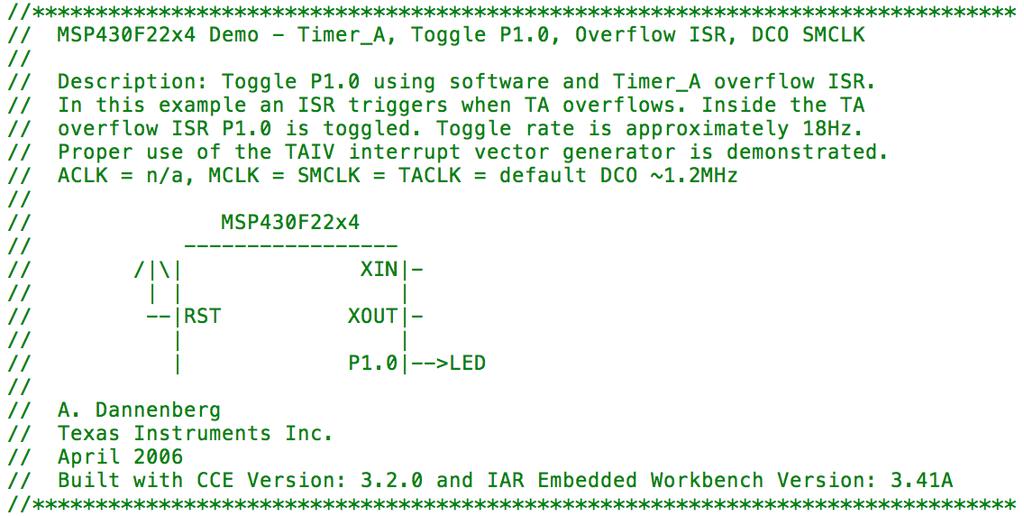
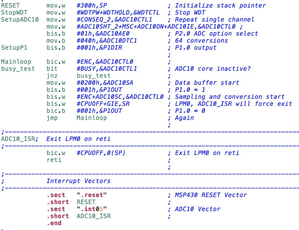
22 msp430x22x4_ta_03
23 msp430x22x4_ta_03
24 msp430x22x4_ta_03
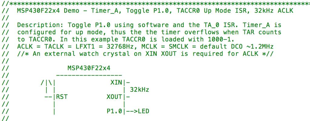
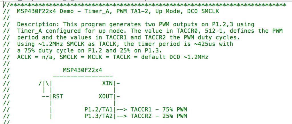
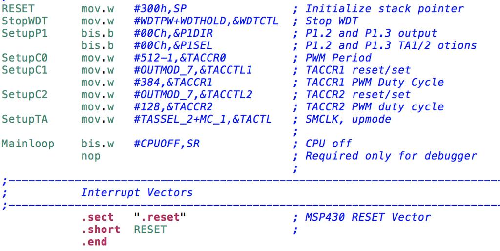
25 msp430x22x4_ta_05
26 msp430x22x4_ta_05
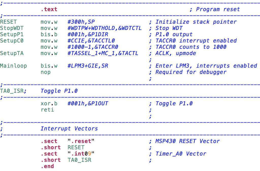
27 msp430x22x4_ta_05
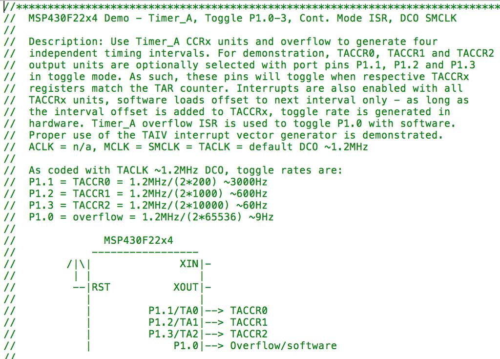
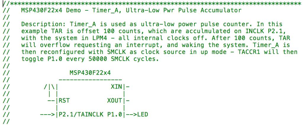
28 msp430x22x4_ta_07
29 msp430x22x4_ta_07
30 msp430x22x4_ta_07
31 msp430x22x4_ta_16
32 msp430x22x4_ta_16
33 msp430x22x4_ta_16
34 msp430x22x4_ta_22
35 ta_22
Lab 5 Timer Module PWM ReadMeFirst
 Lab 5 Timer Module PWM ReadMeFirst Lab Folder Content 1) ReadMeFirst 2) Interrupt Vector Table 3) Pin out Summary 4) DriverLib API 5) SineTable Overview In this lab, we are going to use the output hardware
ME 461 Laboratory #2 Timers and Pulse-Width Modulation
 ME 461 Laboratory #2 Timers and Pulse-Width Modulation Goals: 1. Understand how to use timers to control the frequency at which events occur. 2. Generate PWM signals using Timer A. 3. Explore the frequency
Course Introduction. Content 20 pages 3 questions. Learning Time 30 minutes
 Purpose The intent of this course is to provide you with information about the main features of the S08 Timer/PWM (TPM) interface module and how to configure and use it in common applications. Objectives
University of Texas at El Paso Electrical and Computer Engineering Department
 University of Texas at El Paso Electrical and Computer Engineering Department EE 3176 Laboratory for Microprocessors I Fall 2016 LAB 05 Pulse Width Modulation Goals: Bonus: Pre Lab Questions: Use Port
Lazy Clock Electronics and Software
 Lazy Clock Electronics and Software Introduction The Lazy Clock is a wood gear mechanical clock driven by a low-power solenoid that fires only once per minute. An MSP430 microcontroller, clocked with a
Grundlagen Microcontroller Counter/Timer. Günther Gridling Bettina Weiss
 Grundlagen Microcontroller Counter/Timer Günther Gridling Bettina Weiss 1 Counter/Timer Lecture Overview Counter Timer Prescaler Input Capture Output Compare PWM 2 important feature of microcontroller
Microcontrollers: Lecture 3 Interrupts, Timers. Michele Magno
 Microcontrollers: Lecture 3 Interrupts, Timers Michele Magno 1 Calendar 07.04.2017: Power consumption; Low power States; Buses, Memory, GPIOs 20.04.2017 Serial Communications 21.04.2017 Programming STM32
Microcontroller: Timers, ADC
 Microcontroller: Timers, ADC Amarjeet Singh February 1, 2013 Logistics Please share the JTAG and USB cables for your assignment Lecture tomorrow by Nipun 2 Revision from last class When servicing an interrupt,
ECE 511: FINAL PROJECT REPORT GROUP 7 MSP430 TANK
 ECE 511: FINAL PROJECT REPORT GROUP 7 MSP430 TANK Team Members: Andrew Blanford Matthew Drummond Krishnaveni Das Dheeraj Reddy 1 Abstract: The goal of the project was to build an interactive and mobile
Review for Final Exam
 Review for Final Exam Numbers Decimal to Hex (signed and unsigned) Hex to Decimal (signed and unsigned) Binary to Hex Hex to Binary Addition and subtraction of fixed-length hex numbers Overflow, Carry,
Timer A. Last updated 8/7/18
 Last updated 8/7/18 Advanced Timer Functions Output Compare Sets a flag and/or creates an interrupt when the counter value matches a value programmed into a separate register Input Capture Captures the
Lecture 6: More on Timers and PWM
 ECE342 Digital II Lecture 6: More on Timers and PWM Ying Tang Electrical and Computer Engineering Rowan University 1 Timer in Capture Mode What Does a Timer Really Do? Capture a selected input from either
VORAGO Timer (TIM) subsystem application note
 subsystem application note") AN1202 VORAGO Timer (TIM) subsystem application note Feb 24, 2017, Version 1.2 VA10800/VA10820 Abstract This application note reviews the Timer (TIM) subsystem on the VA108xx family of MCUs and provides
AN1202 VORAGO Timer (TIM) subsystem application note Feb 24, 2017, Version 1.2 VA10800/VA10820 Abstract This application note reviews the Timer (TIM) subsystem on the VA108xx family of MCUs and provides
Hello, and welcome to this presentation of the STM32 Digital Filter for Sigma-Delta modulators interface. The features of this interface, which
 Hello, and welcome to this presentation of the STM32 Digital Filter for Sigma-Delta modulators interface. The features of this interface, which behaves like ADC with external analog part and configurable
EEL 4744C: Microprocessor Applications Lecture 8 Timer Dr. Tao Li
 EEL 4744C: Microprocessor Applications Lecture 8 Timer Reading Assignment Software and Hardware Engineering (new version): Chapter 14 SHE (old version): Chapter 10 HC12 Data Sheet: Chapters 12, 13, 11,
Reading Assignment. Timer. Introduction. Timer Overview. Programming HC12 Timer. An Overview of HC12 Timer. EEL 4744C: Microprocessor Applications
 Reading Assignment EEL 4744C: Microprocessor Applications Lecture 8 Timer Software and Hardware Engineering (new version): Chapter 4 SHE (old version): Chapter 0 HC Data Sheet: Chapters,,, 0 Introduction
PWM System. Microcomputer Architecture and Interfacing Colorado School of Mines Professor William Hoff
 PWM System 1 Pulse Width Modulation (PWM) Pulses are continuously generated which have different widths but the same period between leading edges Duty cycle (% high) controls the average analog voltage
This section describes the basic functions of a the general purpose 16-bit Timer_A in MSP430 based system.
 MSP43 Family _A _A This section describes the basic functions of a the general purpose 6-bit _A in MSP43 based system. Topic Page. Operation of _A -3. Registers of _A -7.3 _A in Applications -8.4 _A special
Hello and welcome to this Renesas Interactive Course that provides an overview of the timers found on RL78 MCUs.
 Hello and welcome to this Renesas Interactive Course that provides an overview of the timers found on RL78 MCUs. 1 The purpose of this course is to provide an introduction to the RL78 timer Architecture.
IV B.Tech. I Sem (R13) ECE : Embedded Systems : UNIT -3 1 UNIT 3
 ECE : Embedded Systems : UNIT -3 1 UNIT 3") IV B.Tech. I Sem (R13) ECE : Embedded Systems : UNIT -3 1 UNIT 3 Timers of MSP430 3.1. Basic Timer1 3.2. Timer_A 3.3. Edge aligned PWM output 3.4. Measurement in Capture mode ( Time period, duration, frequency)
IV B.Tech. I Sem (R13) ECE : Embedded Systems : UNIT -3 1 UNIT 3 Timers of MSP430 3.1. Basic Timer1 3.2. Timer_A 3.3. Edge aligned PWM output 3.4. Measurement in Capture mode ( Time period, duration, frequency)
Hello, and welcome to this presentation of the STM32 Infrared Timer. Features of this interface allowing the generation of various IR remote control
 Hello, and welcome to this presentation of the STM32 Infrared Timer. Features of this interface allowing the generation of various IR remote control protocols will be presented. 1 The Infrared Timer peripheral
Hello, and welcome to this presentation of the FlexTimer or FTM module for Kinetis K series MCUs. In this session, you ll learn about the FTM, its
 Hello, and welcome to this presentation of the FlexTimer or FTM module for Kinetis K series MCUs. In this session, you ll learn about the FTM, its main features and the application benefits of leveraging
EE 308 Apr. 24, 2002 Review for Final Exam
 Review for Final Exam Numbers Decimal to Hex (signed and unsigned) Hex to Decimal (signed and unsigned) Binary to Hex Hex to Binary Addition and subtraction of fixed-length hex numbers Overflow, Carry,
Review for Final Exam
 Review for Final Exam Numbers Decimal to Hex (signed and unsigned) Hex to Decimal (signed and unsigned) Binary to Hex Hex to Binary Addition and subtraction of fixed-length hex numbers Overflow, Carry,
Timer 0 Modes of Operation. Normal Mode Clear Timer on Compare Match (CTC) Fast PWM Mode Phase Corrected PWM Mode
 Fast PWM Mode Phase Corrected PWM Mode") Timer 0 Modes of Operation Normal Mode Clear Timer on Compare Match (CTC) Fast PWM Mode Phase Corrected PWM Mode PWM - Introduction Recall: PWM = Pulse Width Modulation We will mostly use it for controlling
Timer 0 Modes of Operation Normal Mode Clear Timer on Compare Match (CTC) Fast PWM Mode Phase Corrected PWM Mode PWM - Introduction Recall: PWM = Pulse Width Modulation We will mostly use it for controlling
Select the single most appropriate response for each question.
 ECE 362 Final Lab Practical - 1 - Practice Exam / Solution PART 1: Multiple Choice Select the single most appropriate response for each question. Note that none of the above MAY be a VALID ANSWER. (Solution
MSP430 Interfacing Programs
 IV B.Tech. I Sem (R13) ECE : Embedded Systems : UNIT -5 1 MSP430 Interfacing Programs 1. Blinking LED 2. LED control using switch 3. GPIO interrupt 4. ADC & PWM application speed control of dc motor 5.
High Resolution Pulse Generation
 High Resolution Pulse Generation An Application Note for the NS9360 Processor www.digi.com 90001138 2009 Digi International Inc. All Rights Reserved. Digi, Digi International, and the Digi logo are trademarks
ME 461 Laboratory #3 Analog-to-Digital Conversion
 ME 461 Laboratory #3 Analog-to-Digital Conversion Goals: 1. Learn how to configure and use the MSP430 s 10-bit SAR ADC. 2. Measure the output voltage of your home-made DAC and compare it to the expected
Graphical Control Panel User Manual
 Graphical Control Panel User Manual DS-MPE-DAQ0804 PCIe Minicard Data Acquisition Module For Universal Driver Version 7.0.0 and later Revision A.0 March 2015 Revision Date Comment A.0 3/18/2015 Initial
DAC A (VCO) Buffer (write) DAC B (AGC) Buffer (write) Pulse Code Buffer (write) Parameter Buffer (write) Figure A.1. Receiver Controller Registers
 Buffer (write) DAC B (AGC) Buffer (write) Pulse Code Buffer (write) Parameter Buffer (write) Figure A.1. Receiver Controller Registers") Appendix A. Host Computer Interface The host computer interface is contained on a plug-in module designed for the IBM PC/XT/AT bus. It includes the converters, counters, registers and programmed-logic
Appendix A. Host Computer Interface The host computer interface is contained on a plug-in module designed for the IBM PC/XT/AT bus. It includes the converters, counters, registers and programmed-logic
Timing System. Timing & PWM System. Timing System components. Usage of Timing System
 Timing & PWM System Timing System Valvano s chapter 6 TIM Block User Guide, Chapter 15 PWM Block User Guide, Chapter 12 1 2 Timing System components Usage of Timing System 3 Counting mechanisms Input time
Fixed-function (FF) implementation for PSoC 3 and PSoC 5 devices
 implementation for PSoC 3 and PSoC 5 devices") 2.40 Features 8- or 16-bit resolution Multiple pulse width output modes Configurable trigger Configurable capture Configurable hardware/software enable Configurable dead band Multiple configurable kill
2.40 Features 8- or 16-bit resolution Multiple pulse width output modes Configurable trigger Configurable capture Configurable hardware/software enable Configurable dead band Multiple configurable kill
Oct 30 Announcements. Bonus marked will be posted today Will provide 270 style feedback on multiple-choice questions. [3.E]-1
![Oct 30 Announcements. Bonus marked will be posted today Will provide 270 style feedback on multiple-choice questions. [3.E]-1](/thumbs/74/70719255.jpg "Oct 30 Announcements. Bonus marked will be posted today Will provide 270 style feedback on multiple-choice questions. [3.E]-1") Oct 30 Announcements Code Marked and on Blackboard This week: Mon 2:30 to 3:00pm, Tues 2:30 to 3:30 and W-F 1:30 to 3:00pm opportunity to talk about code: earn 2 extra points on the coding part Bonus marked
Oct 30 Announcements Code Marked and on Blackboard This week: Mon 2:30 to 3:00pm, Tues 2:30 to 3:30 and W-F 1:30 to 3:00pm opportunity to talk about code: earn 2 extra points on the coding part Bonus marked
Chapter 6 PROGRAMMING THE TIMERS
 Chapter 6 PROGRAMMING THE TIMERS Force Outputs on Outcompare Input Captures Programmabl e Prescaling Prescaling Internal clock inputs Timer-counter Device Free Running Outcompares Lesson 2 Free Running
PIC ADC to PWM and Mosfet Low-Side Driver
 Name Lab Section PIC ADC to PWM and Mosfet Low-Side Driver Lab 6 Introduction: In this lab you will convert an analog voltage into a pulse width modulation (PWM) duty cycle. The source of the analog voltage
PC-OSCILLOSCOPE PCS500. Analog and digital circuit sections. Description of the operation
 PC-OSCILLOSCOPE PCS500 Analog and digital circuit sections Description of the operation Operation of the analog section This description concerns only channel 1 (CH1) input stages. The operation of CH2
CHAPTER 4 CONTROL ALGORITHM FOR PROPOSED H-BRIDGE MULTILEVEL INVERTER
 65 CHAPTER 4 CONTROL ALGORITHM FOR PROPOSED H-BRIDGE MULTILEVEL INVERTER 4.1 INTRODUCTION Many control strategies are available for the control of IMs. The Direct Torque Control (DTC) is one of the most
Fixed-function (FF) implementation for PSoC 3 and PSoC 5LP devices
 implementation for PSoC 3 and PSoC 5LP devices") 3.30 Features 8- or 16-bit resolution Multiple pulse width output modes Configurable trigger Configurable capture Configurable hardware/software enable Configurable dead band Multiple configurable kill
3.30 Features 8- or 16-bit resolution Multiple pulse width output modes Configurable trigger Configurable capture Configurable hardware/software enable Configurable dead band Multiple configurable kill
ECE251: Tuesday October 3 0
 ECE251: Tuesday October 3 0 Timer Module Continued Review Pulse Input Characterization Output Pulses Pulse Count Capture Homework #6 due Thursday Lab 7 (Maskable Interrupts/ SysTick Timer) this week. Significant
WDTCTL = WDTPW + WDTHOLD; P1DIR = 1; // P1.0 output, all others input. sits here as long as the pin is high while (P1IN & 8); while (!
; while (!") Today's plan: Announcements: status report Solution to Activity 4 Final presentations and reports Measuring capacitance Powering your project This is the final Lecture! I will be in the lab next few weeks
Today's plan: Announcements: status report Solution to Activity 4 Final presentations and reports Measuring capacitance Powering your project This is the final Lecture! I will be in the lab next few weeks
Macroblcok MBI5042 Application Note-VB.01-EN
 MBI5042 Application Note (The article is suitable for the IC whose version code is B and datasheet version is VB.0X) Forward MBI5042 uses the embedded PWM signal to control grayscale output and LED current.
CSCI1600 Lab 4: Sound
 CSCI1600 Lab 4: Sound November 1, 2017 1 Objectives By the end of this lab, you will: Connect a speaker and play a tone Use the speaker to play a simple melody Materials: We will be providing the parts
1. Objectives Generation of Gate Drive Signals Inverter Circuitry Initial Testing Inverter Testing 5. 5.
 Experiment 5 Introduction to Photovoltaic Systems and Power Electronics ECEN 4517 Team Members: Ali Abu AlSaud Hassan AlAhmed Tuesday s Lab - Bench 2 Date Performed: April 18, 2017 Instructor: Professor
UNIVERSITY OF VICTORIA FACULTY OF ENGINEERING. SENG 466 Software for Embedded and Mechatronic Systems. Project 1 Report. May 25, 2006.
 UNIVERSITY OF VICTORIA FACULTY OF ENGINEERING SENG 466 Software for Embedded and Mechatronic Systems Project 1 Report May 25, 2006 Group 3 Carl Spani Abe Friesen Lianne Cheng 03-24523 01-27747 01-28963
EIE/ENE 334 Microprocessors
 EIE/ENE 334 Microprocessors Lecture 13: NuMicro NUC140 (cont.) Week #13 : Dejwoot KHAWPARISUTH Adapted from http://webstaff.kmutt.ac.th/~dejwoot.kha/ NuMicro NUC140: Technical Ref. Page 2 Week #13 NuMicro
EE 308 Lab Spring 2009
 9S12 Subsystems: Pulse Width Modulation, A/D Converter, and Synchronous Serial Interface In this sequence of three labs you will learn to use three of the MC9S12's hardware subsystems. WEEK 1 Pulse Width
MSP430 Family Mixed-Signal Microcontroller Application Reports
 MSP430 Family Mixed-Signal Microcontroller Application Reports Author: Lutz Bierl Literature Number: SLAA024 January 2000 Printed on Recycled Paper IMPORTANT NOTICE Texas Instruments and its subsidiaries
Generating DTMF Tones Using Z8 Encore! MCU
 Application Note Generating DTMF Tones Using Z8 Encore! MCU AN024802-0608 Abstract This Application Note describes how Zilog s Z8 Encore! MCU is used as a Dual-Tone Multi- (DTMF) signal encoder to generate
EE 308 Spring Using the HCS12 PWM
 Using the HCS12 PWM 1. Choose 8-bit mode (PWMCTL = x) 2. Choose high polarity (PWMPOL = xff) 3. Choose left-aligned (PWMCAE = x) 4. Select clock mode in PWMCLK: PCLKn = for 2 N, PCLKn = 1 for 2 (N+1) M,
ECE 511: MICROPROCESSORS
 ECE 511: MICROPROCESSORS A project report on SNIFFING DOG Under the guidance of Prof. Jens Peter Kaps By, Preethi Santhanam (G00767634) Ranjit Mandavalli (G00819673) Shaswath Raghavan (G00776950) Swathi
LM4: The timer unit of the MC9S12DP256B/C
 Objectives - To explore the Enhanced Capture Timer unit (ECT) of the MC9S12DP256B/C - To program a real-time clock signal with a fixed period and display it using the onboard LEDs (flashing light) - To
The MC9S12 Pulse Width Modulation System. Pulse Width Modulation
 The MC9S12 Pulse Width Modulation System o Introduction to PWM o Review of the Output Compare Function o Using Output Compare to generate a PWM signal o Registers used to enable the Output Capture Function
nc. Function Set Configuration The 32LQD is the main function of the set. It can be used either alone, with one of the supporting functions, or with b
 nc. Rev. 0, 5/2003 32-bit Linear Quadrature Decoder TPU Function Set (32LQD) By Milan Brejl, Ph.D. Functional Overview 32-bit Linear Quadrature Decoder (32LQD) TPU Function Set is useful for decoding position,
ESE 350 Microcontroller Laboratory Lab 5: Sensor-Actuator Lab
 ESE 350 Microcontroller Laboratory Lab 5: Sensor-Actuator Lab The purpose of this lab is to learn about sensors and use the ADC module to digitize the sensor signals. You will use the digitized signals
Data Converters. Lecture Fall2013 Page 1
 Data Converters Lecture Fall2013 Page 1 Lecture Fall2013 Page 2 Representing Real Numbers Limited # of Bits Many physically-based values are best represented with realnumbers as opposed to a discrete number
RedPitaya. FPGA memory map
 RedPitaya FPGA memory map Written by Revision Description Version Date Matej Oblak Initial 0.1 08/11/13 Matej Oblak Release1 update 0.2 16/12/13 Matej Oblak ASG - added burst mode ASG - buffer read pointer
USB4. Encoder Data Acquisition USB Device Page 1 of 8. Description. Features
 USB4 Page 1 of 8 The USB4 is a data acquisition device designed to record data from 4 incremental encoders, 8 digital inputs and 4 analog input channels. In addition, the USB4 provides 8 digital outputs
ATmega16A Microcontroller
 ATmega16A Microcontroller Timers 1 Timers Timer 0,1,2 8 bits or 16 bits Clock sources: Internal clock, Internal clock with prescaler, External clock (timer 2), Special input pin 2 Features The choice of
PIC Analog Voltage to PWM Duty Cycle
 Name Lab Section PIC Analog Voltage to PWM Duty Cycle Lab 5 Introduction: In this lab you will convert an analog voltage into a pulse width modulation (PWM) duty cycle. The source of the analog voltage
MBI5031 Application Note
 MBI5031 Application Note Foreword MBI5031 is specifically designed for D video applications using internal Pulse Width Modulation (PWM) control, unlike the traditional D drivers with external PWM control,
8253 functions ( General overview )
") What are these? The Intel 8253 and 8254 are Programmable Interval Timers (PITs), which perform timing and counting functions. They are found in all IBM PC compatibles. 82C54 which is a superset of the
What are these? The Intel 8253 and 8254 are Programmable Interval Timers (PITs), which perform timing and counting functions. They are found in all IBM PC compatibles. 82C54 which is a superset of the
Topics Introduction to Microprocessors
 Topics 2244 Introduction to Microprocessors Chapter 8253 Programmable Interval Timer/Counter Suree Pumrin,, Ph.D. Interfacing with 886/888 Programming Mode 2244 Introduction to Microprocessors 2 8253/54
Small DC Motor Control
 APPLICATION NOTE Small DC Motor Control JAFAR MODARES ECO APPLICATIONS September 1988 Order Number 270622-001 Information in this document is provided in connection with Intel products Intel assumes no
Experiment#6: Speaker Control
 Experiment#6: Speaker Control I. Objectives 1. Describe the operation of the driving circuit for SP1 speaker. II. Circuit Description The circuit of speaker and driver is shown in figure# 1 below. The
Microprocessors & Interfacing
 Lecture overview Microprocessors & Interfacing /Output output PMW Digital-to- (D/A) Conversion input -to-digital (A/D) Conversion Lecturer : Dr. Annie Guo S2, 2008 COMP9032 Week9 1 S2, 2008 COMP9032 Week9
EE 308 Spring S12 SUBSYSTEMS: PULSE WIDTH MODULATION, A/D CONVERTER, AND SYNCHRONOUS SERIAN INTERFACE
 9S12 SUBSYSTEMS: PULSE WIDTH MODULATION, A/D CONVERTER, AND SYNCHRONOUS SERIAN INTERFACE In this sequence of three labs you will learn to use the 9S12 S hardware sybsystem. WEEK 1 PULSE WIDTH MODULATION
Product Family: 05, 06, 105, 205, 405, WinPLC, Number: AN-MISC-021 Terminator IO Subject: High speed input/output device
 APPLICATION NOTE THIS INFORMATION PROVIDED BY AUTOMATIONDIRECT.COM TECHNICAL SUPPORT These documents are provided by our technical support department to assist others. We do not guarantee that the data
MICROCONTROLLER TUTORIAL II TIMERS
 MICROCONTROLLER TUTORIAL II TIMERS WHAT IS A TIMER? We use timers every day - the simplest one can be found on your wrist A simple clock will time the seconds, minutes and hours elapsed in a given day
Hardware Flags. and the RTI system. Microcomputer Architecture and Interfacing Colorado School of Mines Professor William Hoff
 Hardware Flags and the RTI system 1 Need for hardware flag Often a microcontroller needs to test whether some event has occurred, and then take an action For example A sensor outputs a pulse when a model
Cleaning Robot Working at Height Final. Fan-Qi XU*
 Proceedings of the 3rd International Conference on Material Engineering and Application (ICMEA 2016) Cleaning Robot Working at Height Final Fan-Qi XU* International School, Beijing University of Posts
Analog Input and Output. Lecturer: Sri Parameswaran Notes by: Annie Guo
 Analog Input and Output Lecturer: Sri Parameswaran Notes by: Annie Guo 1 Analog output Lecture overview PMW Digital-to-Analog (D/A) Conversion Analog input Analog-to-Digital (A/D) Conversion 2 PWM Analog
EE 308 Spring 2013 The MC9S12 Pulse Width Modulation System
 The MC9S12 Pulse Width Modulation System o Introduction to PWM o Review of the Output Compare Function o Using Output Compare to generate a PWM signal o Registers used to enable the Output Capture Function
Utilizing the Trigger Routing Unit for System Level Synchronization
 Engineer-to-Engineer Note EE-360 Technical notes on using Analog Devices DSPs, processors and development tools Visit our Web resources http://www.analog.com/ee-notes and http://www.analog.com/processors
PIC Functionality. General I/O Dedicated Interrupt Change State Interrupt Input Capture Output Compare PWM ADC RS232
 PIC Functionality General I/O Dedicated Interrupt Change State Interrupt Input Capture Output Compare PWM ADC RS232 General I/O Logic Output light LEDs Trigger solenoids Transfer data Logic Input Monitor
TKT-3500 Microcontroller systems
 TKT-3500 Microcontroller systems Lec 4 Timers and other peripherals, pulse-width modulation Ville Kaseva Department of Computer Systems Tampere University of Technology Fall 2010 Sources Original slides
νµθωερτψυιοπασδφγηϕκλζξχϖβνµθωερτ ψυιοπασδφγηϕκλζξχϖβνµθωερτψυιοπα σδφγηϕκλζξχϖβνµθωερτψυιοπασδφγηϕκ χϖβνµθωερτψυιοπασδφγηϕκλζξχϖβνµθ
 θωερτψυιοπασδφγηϕκλζξχϖβνµθωερτψ υιοπασδφγηϕκλζξχϖβνµθωερτψυιοπασδ φγηϕκλζξχϖβνµθωερτψυιοπασδφγηϕκλζ ξχϖβνµθωερτψυιοπασδφγηϕκλζξχϖβνµ EE 331 Design Project Final Report θωερτψυιοπασδφγηϕκλζξχϖβνµθωερτψ
Timer/Counter with PWM
 Timer/Counter with PWM The AVR Microcontroller and Embedded Systems using Assembly and C) by Muhammad Ali Mazidi, Sarmad Naimi, and Sepehr Naimi ATMEL 8-bit AVR Microcontroller with 4/8/16/32K Bytes In-System
µtasker Document µtasker Hardware Timers
 Embedding it better... µtasker Document utaskerhwtimers.doc/0.07 Copyright 2016 M.J.Butcher Consulting Table of Contents 1. Introduction...3 2. Timer Control Interface...3 3. Configuring a Single-Shot
Ocean Controls KT-5198 Dual Bidirectional DC Motor Speed Controller
 Ocean Controls KT-5198 Dual Bidirectional DC Motor Speed Controller Microcontroller Based Controls 2 DC Motors 0-5V Analog, 1-2mS pulse or Serial Inputs for Motor Speed 10KHz, 1.25KHz or 156Hz selectable
AN4507 Application note
 Application note PWM resolution enhancement through a dithering technique for STM32 advanced-configuration, general-purpose and lite timers Introduction Nowadays power-switching electronics exhibit remarkable
Using the HCS08 TPM Module In Motor Control Applications
 Pavel Grasblum Using the HCS08 TPM Module In Motor Control Applications Designers can choose from a wide range of microcontrollers to provide digital control for variable speed drives. Microcontrollers
Micro Controller Based Ac Power Controller
 Wireless Sensor Network, 9, 2, 61-121 doi:1.4236/wsn.9.112 Published Online July 9 (http://www.scirp.org/journal/wsn/). Micro Controller Based Ac Power Controller S. A. HARI PRASAD 1, B. S. KARIYAPPA 1,
OBSOLETE. Bus Compatible Digital PWM Controller, IXDP 610 IXDP 610
 Bus Compatible Digital PWM Controller, IXDP 610 Description The IXDP610 Digital Pulse Width Modulator (DPWM) is a programmable CMOS LSI device which accepts digital pulse width data from a microprocessor
Analog to Digital Conversion
 Analog to Digital Conversion The MSP in the name of our microcontroller MSP430G2554 is abbreviation for Mixed Signal Processor. This means that our microcontroller can be used to handle both analog and
Pulse Width Modulation
 ECEn 621" Computer Arithmetic" Project Notes Week 1 Pulse Width Modulation 1 Pulse Width Modulation A method of regulating the amount of voltage delivered to a load. The average value of the voltage fed
Linear Integrated Circuits
 Linear Integrated Circuits Single Slope ADC Comparator checks input voltage with integrated reference voltage, V REF At the same time the number of clock cycles is being counted. When the integrator output
PCL-836 Multifunction countertimer and digital I/O add-on card for PC/XT/ AT and compatibles
 PCL-836 Multifunction countertimer and digital I/O add-on card for PC/XT/ AT and compatibles Copyright This documentation is copyrighted 1997 by Advantech Co., Ltd. All rights are reserved. Advantech Co.,
Getting Precise with MSP430 Sigma-Delta ADC Peripherals Vincent Chan MSP430 Business Development Manager TI Asia
 Getting Precise with MSP43 Sigma-Delta ADC Peripherals Vincent Chan MSP43 Business Development Manager TI Asia vince-chan@ti.com 25 Texas Instruments Inc, Slide 1 Agenda Sigma-Delta basics & benefits Understanding
The Need. Reliable, repeatable, stable time base. Memory Access. Interval/Event timers ADC DAC
 Timers The Need Reliable, repeatable, stable time base Memory Access /Event timers ADC DAC Time Base: Crystal Oscillator Silicon Dioxide forms a piezoelectric crystal that can deform in eclectic field,
Electric Bike BLDC Hub Motor Control Using the Z8FMC1600 MCU
 Application Note Electric Bike BLDC Hub Motor Control Using the Z8FMC1600 MCU AN026002-0608 Abstract This application note describes a controller for a 200 W, 24 V Brushless DC (BLDC) motor used to power
EVDP610 IXDP610 Digital PWM Controller IC Evaluation Board
 IXDP610 Digital PWM Controller IC Evaluation Board General Description The IXDP610 Digital Pulse Width Modulator (DPWM) is a programmable CMOS LSI device, which accepts digital pulse width data from a
Programming and Interfacing
 AtmelAVR Microcontroller Primer: Programming and Interfacing Second Edition f^r**t>*-**n*c contents Preface xv AtmelAVRArchitecture Overview 1 1.1 ATmegal64 Architecture Overview 1 1.1.1 Reduced Instruction
Pulse Width Modulation
 Pulse Width Modulation Often want to control something by adjusting the percentage of time the object is turned on For example, A DC motor the higher the percentage, the faster the motor goes A light the
Using Z8 Encore! XP MCU for RMS Calculation
 Application te Using Z8 Encore! XP MCU for RMS Calculation Abstract This application note discusses an algorithm for computing the Root Mean Square (RMS) value of a sinusoidal AC input signal using the
Using the Z8 Encore! XP Timer
 Application Note Using the Z8 Encore! XP Timer AN013104-1207 Abstract Zilog s Z8 Encore! XP microcontroller consists of four 16-bit reloadable timers that can be used for timing, event counting or for
Temperature Monitoring and Fan Control with Platform Manager 2
 August 2013 Introduction Technical Note TN1278 The Platform Manager 2 is a fast-reacting, programmable logic based hardware management controller. Platform Manager 2 is an integrated solution combining
Artificial Sine Wave Generation Using SX Communications Controller
 Artificial Sine Wave Generation Using SX Communications Controller Application Note11 Chris Fogelklou November 2000 1.0 Introduciton Sine waves are used extensively in the telecommunications industry,
F²MC-16FX FAMILY ALL SERIES PROGRAMMABLE PULSE GENERATOR 16-BIT MICROCONTROLLER APPLICATION NOTE. Fujitsu Microelectronics Europe Application Note
 Fujitsu Microelectronics Europe Application Note MCU-AN-300201-E-V16 F²MC-16FX FAMILY 16-BIT MICROCONTROLLER ALL SERIES PROGRAMMABLE PULSE GENERATOR APPLICATION NOTE Revision History Revision History Date
354 Facta Universitatis ser.: Elec. and Energ. vol. 13, No.3, December 2000 in the audio frequency band. There are many reasons for moving towards a c
 FACTA UNIVERSITATIS (NI» S) Series: Electronics and Energetics vol. 13, No. 3, December 2000, 353-364 GENERATING DRIVING SIGNALS FOR THREE PHASES INVERTER BY DIGITAL TIMING FUNCTIONS Miroslav Lazić, Miodrag