A Course Material on EE6352- ELECTRICAL ENGINEERING AND INSTRUMENTATION
|
|
|
- Brianne Hill
- 5 years ago
- Views:
Transcription

1 A Course Material on - By Dr. K.Pandiarajan PROFESSOR & HOD DEPARTMENT OF ELECTRONICS AND COMMUNICATION ENGINEERING & S.Vijay ASSISTANT PROFESSOR DEPARTMENT OF ELECTRICAL AND ELECTRONICS ENGINEERING SASURIE COLLEGE OF ENGINEERING, VIJAYAMANGALAM
2 QUALITY CERTIFICATE This is to certify that the course material Subject Code Subject Class : : Electrical Engineering and Instrumentation : II Year Being prepared by us and it meets the knowledge requirement of the university curriculum. Signature of the Author (s) Name Designation Name Designation : Dr.K.Pandiarajan : Professor & HOD : S.Vijay : Assistant Professor This is to certify that the course material being prepared by Dr.K.Pandiarajan & S.Vijay is of adequate quality. They have referred more than five books among them minimum one is from abroad author. Signature of HD Name : Dr. K Pandiarajan SEAL
3 UNIT I DC MACHINES Three Phase Circuits, A Review Construction of DC Machines Theory of Operation Of DC Generators EMF Equation of Generator Characteristics of DC Generators Operating Principle of DC Motors Torque Equation Types of DC Motors and their Characteristics Types of DC Motors D.C Motor Characteristics Speed Control of DC Motors Applications Problems 28 UNIT II TRANSFORMER Introduction Transformer Classification Primary and Secondary Windings Functions of Transformer Parts Principle of Operation Ideal Transformer Single Phase Transformer Construction and Principle of Operation EMF Equation of Transformer 33
4 2.4. Transformer on No Load Transformer on Load Equivalent Circuit of Transformer Equivalent Circuit of Transformer Referred to Primary Approximate Equivalent Circuit of Transformer Equivalent Circuit of Transformer Referred to Secondary Regulation of Transformer Transformer Losses and Efficiency All Day Efficiency Auto Transformer Problems 42 UNIT III INDUCTION MACHINES AND SYNCHRONOUS MACHINES Types, Construction and Working of 3 Phase Induction Motor Equivalent Circuit Construction of Single-Phase Induction Motors Stator of Single Phase Induction Motor Rotor of Single Phase Induction Motor Working Principle of Single Phase Induction Motor Types of Single Phase Induction Motors Double Revolving Field Theory Starting Methods Resistance Split-Phase Motor 50
5 3.6.2 Capacitor-Start Motor Capacitor-start and Capacitor-run Motor Shaded-pole Motor Types, Construction and Working Principle of Alternator Types of Alternator Construction and working principle of Alternator Equation of Induced EMF Voltage Regulation Working Principle and Methods of Starting Of Synchronous Motors V-Curves 60 UNIT IV BASICS OF MEASUREMENT AND INSTRUMENTATION Static and Dynamic Characteristics of Measurement Errors in Measurement Transducers Resistance Transducers Strain gauge Thermistors Capacitive Transducers Piezo electric transducer Variable Inductive Transducers LVDT RVDT 80 UNIT V ANALOG AND DIGITAL INSTRUMENTS Digital Voltmeter (DVM) Digital Multi Meter (DMM) Storage oscilloscope 85
6 5.4 Comparison of analog and digital instruments Wheat stone bridge Kelvin s double bridge Maxwell bridge Schering Bridge Wien Bridge Q-Meter 94 Glossary 96 Two Marks Question & Answers 98 Important Question Bank 112 University Question Bank 119
7 UNIT I DC MACHINES 9 Three phase circuits, a review. Construction of DC machines Theory of operation of DC generators Characteristics of DC generators- Operating principle of DC motors Types of DC motors and their characteristics Speed control of DC motors- Applications. UNIT II TRANSFORMER 9 Introduction Single phase transformer construction and principle of operation EMF equation of transformer-transformer no load phasor diagram - Transformer on load phasor diagram - Equivalent circuit of transformer Regulation of transformer Transformer losses and efficiency- All day efficiency auto transformers. UNIT III INDUCTION MACHINES AND SYNCHRONOUS MACHINES 9 Principle of operation of three-phase induction motors Construction Types Equivalent circuit Construction of single-phase induction motors Types of single phase induction motors Double revolving field theory starting methods - Principles of alternator Construction details Types Equation of induced EMF Voltage regulation. Methods of starting of synchronous motors Torque equation V curves Synchronous motors. UNIT IV BASICS OF MEASUREMENT AND INSTRUMENTATION 9 Static and Dynamic Characteristics of Measurement Errors in Measurement - Classification of Transducers Variable resistive Strainguage, thermistor RTD transducer - Variable Capacitive Transducer Capacitor Microphone - Piezo Electric Transducer Variable Inductive transducer LVDT, RVDT UNIT V ANALOG AND DIGITAL INSTRUMENTS 9 DVM, DMM Storage Oscilloscope. Comparison of Analog and Digital Modes of operation, Application of measurement system, Errors. Measurement of R, L and C, Wheatstone, Kelvin, Maxwell, Anderson, Schering and Wien bridges Measurement of Inductance, Capacitance, Effective resistance at high frequency, Q-Meter. TOTAL (L:45+T:15): 60 PERIODS TEXT BOOKS: 1. I.J Nagarath and Kothari DP, Electrical Machines, McGraw-Hill Education (India) Pvt Ltd 4 th Edition, A.K.Sawhney, A Course in Electrical & Electronic Measurements and Instrumentation, Dhanpat Rai and Co, REFERENCES: 1. Del Toro, Electrical Engineering Fundamentals Pearson Education, New Delhi, W.D.Cooper & A.D.Helfrick, Modern Electronic Instrumentation and Measurement Techniques, 5 th Edition, PHI, John Bird, Electrical Circuit Theory and Technology, Elsevier, First Indian Edition, Thereja.B.L, Fundamentals of Electrical Engineering and Electronics, S Chand & Co Ltd, H.S.Kalsi, Electronic Instrumentation, Tata Mc Graw-Hill Education, J.B.Gupta, Measurements and Instrumentation, S K Kataria & Sons, Delhi, 2003.

8 UNIT I DC MACHINES 1.1 Three Phase Circuits, A Review Polyphase System Circuit or system in which AC sources operate at the same frequency but different phases are known as polyphase. Two Phase System A generator consists of two coils placed perpendicular to each other. The voltage generated by one lags the other by 90. Three Phase System A generator consists of three coils placed 120 apart. The voltage generated are equal in magnitude but, out of phase by 120. Three phase is the most economical polyphase system. Importance of Three Phase System Uniform power transmission and less vibration of three phase machines. The instantaneous power in a 3 system can be constant (not pulsating). High power motors prefer a steady torque especially one created by a rotating magnetic field. Three phase system is more economical than the single phase. The amount of wire required for a three phase system is less than required for an equivalent single phase system. Three Phase Generation Fig. 1.1 Three phase generator Working The generator consists of a rotating magnet (rotor) surrounded by a stationary winding (stator). 1


9 Three separate windings or coils with terminals a-a, b-b, and c-c are physically placed 120 apart around the stator. As the rotor rotates, its magnetic field cuts the flux from the three coils and induces voltages in the coils. The induced voltage have equal magnitude but out of phase by 120. Three-Phase Waveform Fig. 1.2 Three phase waveform Three Phase Quantities Balanced 3 Voltages Balanced three phase voltages: Same magnitude (VM ) 120 phase shift Balanced 3 Currents Balanced three phase currents: Same magnitude (IM ) 120 phase shift 2

10 Phase Sequence Positive Sequence Van VM 0 Vbn VM 120 Vcn VM 120 Fig. 1.3 Positive Sequence Negative Sequence Van VM 0 Vbn VM 120 Vcn VM 120 Fig. 1.4 Negative Sequence 3
 pa (t ) pb (t ) pc (t ) VM I M cos 2 3Vrms I rms cos( ) 3 Three Phase Connection")
11 POWER The instantaneous power is constant. p (t ) pa (t ) pb (t ) pc (t ) VM I M cos 2 3Vrms I rms cos( ) 3 Three Phase Connection Source-Load Connection WYE Connection Fig. 1.5 WYE Connection 4
12 WYE Connected Load Fig. 1.6 WYE Connected Load Balanced Y-Y Connection Fig. 1.7 Balanced Y-Y Connection Phase Currents and Line Currents In Y-Y system, line current is equal to phase current, IL = IP Delta Connection Delta Connected Sources Fig. 1.8 Delta Connected Sources 5
13 DELTA Connected Load Fig. 1.9 Delta Connected Load Balanced - Connection Fig Balanced - Connection PHASE VOLTAGE AND LINE VOLTAGE In - system, line voltages are equal to phase voltages: VL = VP 6
14 Power Measurement in a Three Phase Circuit Using Two-Wattmeter Method Fig Circuit Diagram Phasor Diagram Fig Phasor Diagram The reading of the first wattmeter is, The reading of the second wattmeter is, The sum of the two wattmeter readings is, 7
15 The difference of the two wattmeter readings is, Power factor (cosф) can be determined using the above expression. 1.2 Construction of DC Machines Fig Sectional View of DC Machine It consists of 1. Stator (Stationary part) 2. Rotor (Rotating part) Stator The stator of the dc machine has poles, which are excited by either dc current or permanent magnets to produce magnetic fields. In the neutral zone, in the middle between the poles, commutating poles are placed to reduce sparking of the commutator. Compensating windings are mounted on the main poles. These reduce flux weakening commutation problems. The poles are mounted on an iron core that provides a closed magnetic circuit. 8

16 Rotor The rotor has a ring-shaped laminated iron core with slots. Coils with several turns are placed in the slots. The distance between the two legs of the coil is about 180 electric degrees. The rotor coils are connected in series through the commutator segments. The ends of each coil are connected to a commutator segment. The commutator consists of insulated copper segments mounted on an insulated tube. Two brushes are pressed to the commutator to permit current flow and they are placed in neutral zone. 1.3 Theory of Operation Of DC Generators A generator works on the principles of Faraday s law of electromagnetic induction. It states that Whenever a conductor is moved in the magnetic field, an emf is induced and the magnitude of the induced emf is directly proportional to the rate of change of flux linkage. This emf causes a current flow if the conductor circuit is closed. Fig Elementary Generator The pole pieces (marked N and S) provide the magnetic field. The pole pieces are shaped and positioned as shown above to concentrate the magnetic field as close as possible to the wire loop. The loop of wire that rotates through the field is called the ARMATURE. The ends of the armature loop are connected to rings called SLIP RINGS. They rotate with the armature. The brushes, usually made of carbon, with wires attached to them, ride against the rings. The generated voltage appears across these brushes. The elementary generator produces a voltage in the following manner. 9
 At 0º the armature loop is perpendicular to the magnetic field. The black and white conductors of the loop are moving parallel to the field.")
17 Fig EMF Generation The armature loop is rotated in a clockwise direction. The initial or starting point is shown at position A. (This will be considered the zero-degree position.) At 0º the armature loop is perpendicular to the magnetic field. The black and white conductors of the loop are moving parallel to the field. The instant the conductors are moving parallel to the magnetic field, they do not cut any lines of flux. Therefore, no emf is induced in the conductors, and the meter at position A indicates zero. This position is called the NEUTRAL PLANE. As the armature loop rotates from position A (0º) to position B (90º), the conductors cut through more and more lines of flux, at a continually increasing angle. At 90º they are cutting through a maximum number of lines of flux and at maximum angle. The result is that between 0º and 90º the induced emf in the conductors builds up from zero to a maximum value. Observe that from 0º to 90º the black conductor cuts DOWN through the field. At the same time the white conductor cuts UP through the field. The induced emfs in the conductors are series-adding. This means the resultant voltage across the brushes (the terminal voltage) is the sum of the two induced voltages. The meter at position B reads maximum value. As the armature loop continues rotating from 90º (position B) to 180º (position C), the conductors which were cutting through a maximum number of lines of flux at position B now cut through fewer lines. They are again moving parallel to the magnetic field at position C. They no longer cut through any lines of flux. As the armature rotates from 90º to 180º, the induced voltage will decrease to zero in the same manner that it increased during the rotation from 0º to 90º. The meter again reads zero. From 0º to 180º the conductors of the armature loop have been moving in the same direction through the magnetic field. Therefore, the polarity of the induced voltage has remained the same. This is shown by points A through C on the graph. As the loop rotates beyond 180º (position C), through 270º (position D), and back to the initial or starting point (position A), the direction of the cutting action of the conductors through the magnetic field reverses. Now the black conductor cuts UP through the field while the white conductor cuts DOWN through the field. As a result, the polarity of the induced voltage reverses. Following the sequence shown by graph points C, D, and back to A, the voltage will be in the direction opposite to that shown from points A, B, and C. The terminal voltage will be the same as it was from A to C except that the polarity is reversed (as shown by the meter deflection at 10

18 position D). The voltage output waveform for the complete revolution of the loop is shown in figure Fig Output voltage waveform EMF Equation of Generator Let Φ = flux/pole in webers Z = total number of armature conductors = No. of slots x No. of conductors/slot P = No. of poles A = No. of parallel paths in armature N = Armature rotation in revolutions per minute (r.p.m) E = e.m.f induced in any parallel path in armature Average e.m.f generated /conductor = dφ/dt volt (n=1) Now, flux cut/conductor in one revolution dφ = ΦP Wb No. of revolutions/second = N/60 Time for one revolution, dt = 60/N second According to Faraday's Laws of Electromagnetic Induction, E.M.F generated/conductor is For a simplex wave-wound generator No. of parallel paths = 2 No. of conductors (in series) in one path = Z/2 E.M.F. generated/path is For a simplex lap-wound generator No. of parallel paths = P No. of conductors (in series) in one path = Z/P E.M.F.generated/path 11
19 In general generated e.m.f Where, A = 2 for simplex wave-winding. A = P for simplex lap-winding Characteristics of DC Generators The magnetic field in a d.c. generator is normally produced by electromagnets rather than permanent magnets. Generators are generally classified according to their methods of field excitation. On this basis, d.c. generators are divided into the following two classes: (i) Separately excited d.c. generators (ii) Self-excited d.c. generators The behavior of a d.c. generator on load depends upon the method of field excitation adopted. There are two characteristics 1. Magnetic (no load or open circuit) characteristics This curve shows the relation between the generated e.m.f. at no-load (E0) and the field current (If) at constant speed. It is also known as magnetic characteristic or no-load saturation curve. Its shape is practically the same for all generators whether separately or self-excited. The data for O.C.C. curve are obtained experimentally by operating the generator at no load and constant speed and recording the change in terminal voltage as the field current is varied. 2. Internal and External characteristics Internal characteristics This curve shows the relation between the generated e.m.f. on load (E or Eg) and the armature current (Ia). The e.m.f. E is less than E0 due to the demagnetizing effect of armature reaction. Therefore, this curve will lie below the open circuit characteristic (O.C.C.). The internal characteristic is of interest chiefly to the designer. It cannot be obtained directly by experiment. It is because a voltmeter cannot read the e.m.f. generated on load due to the voltage drop in armature resistance. The internal characteristic can be obtained from external characteristic if winding resistances are known because armature reaction effect is included in both characteristics External characteristics This curve shows the relation between the terminal voltage (Vt) and load current (IL). The terminal voltage Vt will be less than E due to voltage drop in the armature circuit. Therefore, this curve will lie below the internal characteristic. This characteristic is very important in determining the suitability of a generator for a given purpose. It can be obtained by making simultaneous (i) Separately Excited D.C. Generators A d.c. generator whose field magnet winding is supplied from an independent external d.c. source (e.g., a battery etc.) is called a separately excited generator. The connections of a separately excited generator are shown below. The voltage output depends upon the speed of rotation of armature and the field current. The greater the speed and field current, greater is the 12
 Fig.")
20 generated e.m.f. It may be noted that separately excited d.c. generators are rarely used in practice. The d.c. generators are normally of self-excited type. Fig Separately Excited DC Generator Armature current, Ia = IL Terminal voltage, Vt = Eg IaRa Electric power developed = EgIa Power delivered to load = VIL Magnetic characteristics (E0 versus If) Fig Magnetic Characteristics A separate excitation is normally used for testing of d.c. generators to determine their open circuit or magnetization characteristic. The excitation current is increased monotonically to a maximum value and then decreased in the same manner, while noting the terminal voltage of the armature. The load current is kept zero. The speed of the generator is held at a constant value. The graph showing the nature of variation of the induced emf as a function of the excitation current is called as open circuit characteristic (occ), or no-load magnetization curve or no-load saturation characteristic. 13
21 Internal and External characteristics Fig Internal and External Characteristics (ii) Self-excited D.C. Generators a). D.C. Series Generator Fig DC Series Generator Armature current, Ia = Ise = IL Terminal voltage, Vt = Eg - Ia(Ra + Rse) Power developed in armature = EgIa Power delivered to load = VIa or VIL 14
22 No load and Load Characteristics Fig No Load and Load Characteristics b). D.C. Shunt Generator Fig DC shunt generator Shunt field current, Ish = V/Rsh Armature current, Ia = IL + Ish Terminal voltage, Vt = Eg - IaRa Power developed in armature = EgIa Power delivered to load = VtIL 15
23 Internal and External Characteristics Fig Internal Characteristics Fig External Characteristics c). D.C. Compound Generator In a compound-wound generator, there are two sets of field windings on each pole one is in series and the other in parallel with the armature. A compound wound generator may be: Short Shunt in which only shunt field winding is in parallel with the armature winding. Long Shunt in which shunt field winding is in parallel with both series field and armature winding 16
24 1. Long shunt compound generator Fig Long Shunt Compound Generator Series field current, Ise = Ia = IL+Ish Shunt field current, Ish = V/Rsh Terminal voltage, Vt = Eg - Ia(Ra+Rse) Power developed in armature = EgIa Power delivered to load = VtIL 2. Short shunt compound generator Fig Short Shunt Compound Generator Series field current, Ise = IL Shunt field current, Ish = V+IseRse/Rsh Terminal voltage, Vt = Eg - IaRa+IseRse Power developed in armature = EgIa Power delivered to load = VtIL 17


25 External Characteristics Fig External Characteristics 1.5. Operating Principle of DC Motors It is based on the principle that when a current-carrying conductor is placed in a magnetic field, it experiences a mechanical force whose direction is given by Fleming's Left-hand rule and whose magnitude is given by Force, F = B I l Newton Where, B is the magnetic field in weber/m2. I is the current in amperes and l is the length of the coil in meter. Fig Elementary Motor 18

 = (FXR)(2πN/60) P = T x ω watts Power in armature = armature torque x ω EbIa = Ta x (2ΠN/60) Where, Ta = Armature torque.")
26 1.5.1 Torque Equation Turning or twisting force about an axis is called torque. Consider a wheel of radius R meters acted upon by a circumferential force F Newton s as shown in above figure. The wheel is rotating at a speed of N rpm. The angular speed of the wheel ω = 2πN/60 rad/sec Work done in one revolution W= Force x distanced travelled in one revolution W = FX2πR joules Power developed, P = Work done/time = W/Time for 1 rev. P = FX2πR/(60/N) = (FXR)(2πN/60) P = T x ω watts Power in armature = armature torque x ω EbIa = Ta x (2ΠN/60) Where, Ta = Armature torque. Eb = PΦZN/60A Substituting Eb values, we get, Ta = 0.159ΦIa (PZ/A) N-m 1.6 Types of DC Motors and their Characteristics Types of DC Motors Fig Motor Classification 19
27 1. D.C Shunt Motor In shunt wound motor the field winding is connected in parallel with armature. The current through the shunt field winding is not the same as the armature current. Shunt field windings are designed to produce the necessary m.m.f. by means of a relatively large number of turns of wire having high resistance. Therefore, shunt field current is relatively small compared with the armature current Fig DC Shunt Motor 2. D.C Series Motor In series wound motor the field winding is connected in series with the armature. Therefore, series field winding carries the armature current. Since the current passing through a series field winding is the same as the armature current, series field windings must be designed with much fewer turns than shunt field windings for the same mmf. Therefore, a series field winding has a relatively small number of turns of thick wire and, therefore, will possess a low resistance. Fig DC Series Motor 3. D.C Compound Motor Compound wound motor has two field windings; one connected in parallel with the armature and the other in series with it. There are two types of compound motor connections 1) Short-shunt connection 20
28 2) Long shunt connection 1) Short-shunt connection When the shunt field winding is directly connected across the armature terminals it is called short-shunt connection. Fig DC Compound Motor (Short shunt) 2) Long shunt connection When the shunt winding is so connected that it shunts the series combination of armature and series field it is called long-shunt connection. Fig DC Compound Motor (Long shunt) 21
29 1.6.2 D.C Motor Characteristics 1. D.C Shunt Motor a. Torque versus Armature current Ta is proportional to Ia Fig Torque Vs Armature Current b. Speed versus Armature current Fig Speed Vs Armature Current c. Speed versus Torque Fig Speed Vs Torque 22
30 2. D.C Series Motor a. Torque versus Armature current Ta is proportional to Ia2 Fig Torque Vs Armature Current b. Speed versus Armature current Fig Speed Vs Armature Current c. Speed versus Torque Fig Speed Vs Torque 23
31 3. D.C Compound Motor Fig DC Compound Motor Characteristics 1.7 Speed Control of DC Motors DC shunt motor i. Flux control Fig Flux Control 24
32 Fig Speed Vs Shunt Field Current As speed is inversely proportional to the flux. The flux is dependent on the current through the shunt field winding. Thus flux can be controlled by adding a rheostat (variable resistance in series with the shunt field winding as shown in above figure. At the beginning the rheostat is kept at minimum. The supply voltage is at rated value. So current through the shunt field winding is also its rated value. Hence the speed is also the rated value. Resistance is increased, shunt field current is reduced (flux is reduced) and speed is increased beyond its rated value. ii. Armature voltage control or rheostatic control Fig Rheostatic Control 25
33 Fig Speed Vs Voltage across Armature The speed is directly proportional to the voltage applied across the armature. As the supply voltage is normally constant, the voltage across the armature can be controlled by adding a variable resistance in series with the armature as shown in figure above. iii. Applied voltage control Fig Multiple Voltage Control Shunt field of the motor is permanently connected to the fixed voltage supply. Armature is supplied with various voltages by means of suitable switchgear arrangements. 26

34 iv. Potential divider control Fig Potential Divider Arrangement Fig Speed Vs Voltage When the variable rheostat position is at start point shown, voltage across the armature is zero. As rheostat is moved towards minimum point shown, the voltage across the armature increases, increasing the speed. At maximum point the voltage is maximum and speed is rated value. 27
35 1.8 APPLICATIONS Type of Motor Shunt Characteristics Speed is fairly constant and medium starting torque. Series High starting torque. No load condition is dangerous. Variable speed. Cumulative compound High starting torque. No load condition is allowed. Differential compound Speed increases as load increases. Applications 1. Blowers and fans 2. Centrifugal and reciprocating pumps 3. Lathe machines 4. Machine tools 5. Milling machines 6. Drilling machines 1. Cranes 2. Hoists, Elevators 3. Trolleys 4. Conveyors 5. Electric locomotives 1. Rolling mills 2. Punches 3. Shears 4. Heavy planers 5. Elevators Not suitable for any practical applications 1.9 PROBLEMS 1. A 4 pole generator with wave wound armature has 51 slots each having 24 conductors. The flux per pole is 10 mwb. At what speed must the armature rotate to give an induced emf of 0.24 kv. What will be the voltage developed, if the winding is lap connected and the armature rotates at the same speed? Given data P=4 No.of slots = 51 No.of conductors/slot = 20 Eg= 0.24 Kv = 240 V Φ = 10 mw= 10/1000 Web Find N & Eg at same N? Solution Total no. of conductors, Z = 51x20 = 1224 Wave winding, A=2 28
36 From EMF equation, N= Eg60A / ΦZP = (240x60x2)/(10/1000x1224x4) = rpm Lap winding, A=P=4 Eg = PΦZN/60A = (4x10/1000x1224x612.75)/(60x4) = kv 2. A 250 volt DC shunt motor has armature resistance of 0.25 ohm on load it takes an armature current of 50A and runs at 750rpm. If the flux of the motor is reduced by 10% without changing the load torque, find the new speed of the motor. Given data V = 250 Ra = 0.25 Ia = 50 N1 = 750 Φ2 = 90%Φ1 Find N2? Solution N 2 Eb 2 1 N1 E b1 2 Eb1 = V-Ia1Ra = 250-(50x0.25) = 237.5V Eb2 = V-Ia2Ra Load torque is constant Ta1 = Ta2 Φ1Ia1 = Φ2Ia2 Ia2 = 55.55A Eb2 = X0.25 = V N2 = 828 rpm UNIT II TRANSFORMER 2.1 Introduction A transformer is a device that changes ac electric power at one voltage level to ac electric power at another voltage level through the action of a magnetic field. 29

37 There are two or more stationary electric circuits that are coupled magnetically. It involves interchange of electric energy between two or more electric systems. Transformers provide much needed capability of changing the voltage and current levels easily. They are used to step-up generator voltage to an appropriate voltage level for power transfer. Stepping down the transmission voltage at various levels for distribution and power utilization Transformer Classification In terms of number of windings Conventional transformer: two windings Autotransformer: one winding Others: more than two windings In terms of number of phases Single-phase transformer Three-phase transformer Depending on the voltage level at which the winding is operated Step-up transformer: primary winding is a low voltage (LV) winding Step-down transformer : primary winding is a high voltage (HV) winding Primary and Secondary Windings A two-winding transformer is shown below. It consists of two windings interlinked by a mutual magnetic field. Primary winding energized by connecting it to an input source. Secondary winding winding to which an electrical load is connected and from which output energy is drawn. Fig. 2.1 Two Winding Transformer 30

38 2.1.3 Functions of Transformer Parts Parts Function Core Provides a path for the magnetic. Primary winding Receives the energy from the ac source. Secondary winding Receives energy from the primary winding and delivers it to the load. Enclosure Protects the above components from dirt, moisture, and damage Principle of Operation When current in the primary coil changes being alternating in nature, a changing magnetic field is produced This changing magnetic field gets associated with the secondary through the soft iron core Hence magnetic flux linked with the secondary coil changes. Which induces e.m.f. in the secondary Ideal Transformer An ideal transformer is a transformer which has no loses, i.e. it s winding has no ohmic resistance, no magnetic leakage, and therefore no I2 R and core loses. However, it is impossible to realize such a transformer in practice. Yet, the approximate characteristic of ideal transformer will be used in characterized the practical transformer. For ideal transformer E1=V1 and E2= V2 2.2 Single Phase Transformer Construction and Principle of Operation Construction It consisted of two electric circuits linked by a common magnetic circuit helped the voltage and current levels to be changed keeping the power invariant. It has two types such as core type and shell type which is shown below. 31
39 Fig. 2.2 Core Type Fig. 2.3 Shell Type Core type construction the windings are wound around the two legs of a rectangular magnetic core. Shell type construction the windings are wound on the central leg of a three legged core. There are two basic parts of a transformer i) Magnetic core ii) Winding or coils. The core of the transformer is either square or rectangular in size. The vertical portion on which coils are wound is called limb. The top and bottom horizontal portion is called yoke of the core. There are two winding in a transformer such as primary and secondary. This excitation winding is called a primary and the output winding is called a secondary. The primary and secondary windings are wound with copper (sometimes aluminium in small transformers) conductors. As a magnetic medium forms the link between the primary and the secondary windings there is no conductive connection between the two electric circuits. 32
40 Principle of operation It operates on the principle of mutual induction between two inductively coupled coils. It consists of two inductive coils which are electrically separated but magnetically coupled to a core. If the coil is connected to a source of alternating voltage an alternating flux is produced in the laminated core. Most of the flux is linked with the coil. Thus flux is called mutual flux. As per faraday s laws of electromagnetic induction, an emf is induced in the secondary coil. If the secondary coil circuit is closed, a current flow in it and thus electrical energy is transferred from the first coil to the second coil. 2.3 EMF Equation of Transformer Let, N1=Primary number of turns N2 =Secondary number of turns f = Frequency of supply in Hz The flux in the core will be sinusoidally as shown below. Fig. 2.4 Flux in the Core The flux in the core increases from zero to Φ m in one quarter cycle (1/4 second) Therefore, average rate of change of flux = Φm/(1/4f) = 4f Φm Average emf induced per turn = Average rate change of flux x 1 =4f Φm Volts RMS value of induced emf per turn = 1.11 x 4f Φ m = 4.44f Φm Volts RMS value of induced emf in primary, E1 = 4.44f Φm N1 Volts RMS value of induced emf in secondary, E2 = 4.44f Φm N2 Volts In an ideal transformer on no load, V1 = E1, V2 = E2 2.4 Transformer on No Load When the primary of a transformer is connected to the source of an ac supply and the secondary is open circuited as shown below, the transformer is said to be on no load. The Transformer on no load alternating applied voltage will cause flow of an alternating current I0 in the primary winding, which will create alternating flux Ф. No-load current I0, also known as excitation or exciting current, has two components the magnetizing component Im and the energy component 33

41 Ie as shown in phasor diagram. Im is used to create the flux in the core and Ie is used to overcome the hysteresis and eddy current losses occurring in the core in addition to small amount of copper losses occurring in the primary only (no copper loss occurs in the secondary, because it carries no current, being open circuited.) Fig. 2.5 Transformer on No Load 2.5 Transformer on Load The transformer is said to be loaded, when its secondary circuit is completed through an impedance or load. The magnitude and phase of secondary current (i.e. current flowing through secondary) I2 with respect to secondary terminals depends upon the characteristic of the load i.e. current I2 will be in phase, lag behind and lead the terminal voltage V2 respectively when the load is non-inductive, inductive and capacitive. The net flux passing through the core remains almost constant from no-load to full load irrespective of load conditions and so core losses remain almost constant from no-load to full load. Vector diagram for an ideal transformer supplying inductive load which is shown below. Fig. 2.6 Phasor Diagram - Transformer on Load 34
42 In actual practice, both of the primary and have got some ohmic resistance causing voltage drops and copper losses in the windings. In actual practice, the total flux created does not link both of the primary and secondary windings but is divided into three components namely the main or mutual flux linking both of the primary and secondary windings, primary leakage flux linking with primary winding only and secondary leakage flux linking with secondary winding only. The primary leakage flux is produced by primary ampere-turns and is proportional to primary current, number of primary turns being fixed. The primary leakage flux is in phase with and produces self induced emf is in phase with and produces self induced emf E given as 2f in the primary winding. The self induced emf divided by the primary current gives the reactance of primary and is denoted by E = 2fπ 2.6 Equivalent Circuit of Transformer Equivalent impedance of transformer is essential to be calculated because the electrical power transformer is an electrical power system equipment for estimating different parameters of electrical power system which may be required to calculate total internal impedance of an electrical power transformer, viewing from primary side or secondary side as per requirement. This calculation requires equivalent circuit of transformer referred to primary or equivalent circuit of transformer referred to secondary sides respectively. Percentage impedance is also very essential parameter of transformer. Special attention is to be given to this parameter during installing a transformer in an existing electrical power system. Percentage impedance of different power transformers should be properly matched during parallel operation of power transformers. The percentage impedance can be derived from equivalent impedance of transformer so, it can be said that equivalent circuit of transformer is also required during calculation of % impedance Equivalent Circuit of Transformer Referred to Primary For drawing equivalent circuit of transformer referred to primary, first we have to establish general equivalent circuit of transformer then; we will modify it for referring from primary side. For doing this, first we need to recall the complete vector diagram of a transformer as shown in figure

43 Fig. 2.7 Vector Diagram Let us consider the transformation ratio be, In figure 2.7, the applied voltage to the primary is V1 and voltage across the primary winding is E1. Total current supplied to primary is I1. So the voltage V1 applied to the primary is partly dropped by I1Z1 or I1R1 + j.i1x1 before it appears across primary winding. The voltage appeared across winding is countered by primary induced emf E1. From the vector diagram above, it is found that the total primary current I1 has two components, one is no - load component Io and the other is load component I2. As this primary current has two a component or branches, so there must be a parallel path with primary winding of transformer. This parallel path of current is known as excitation branch of equivalent circuit of transformer. The resistive and reactive branches of the excitation circuit can be represented as, The equivalent circuit for that equation can be drawn as below, 36
44 Fig. 2.8 Equivalent Circuit Fig. 2.9 Equivalent Circuit of Primary Side Fig Equivalent Circuit of Transformer Referred to Primary Again I2.N1 = I2.N2 Therefore, From above equation, secondary impedance of transformer referred to primary is, 37
45 2.6.2 Approximate Equivalent Circuit of Transformer Since Io is very small compared to I1, it is less than 5% of full load primary current, Io changes the voltage drop insignificantly. Hence, it is good approximation to ignore the excitation circuit in approximate equivalent circuit of transformer. The winding resistance and reactance being in series can now be combined into equivalent resistance and reactance of transformer, referred to any particular side. In this case it is side 1 or primary side. Fig Approximate Equivalent Circuit of Transformer Referred to Primary Equivalent Circuit of Transformer Referred to Secondary In similar way, approximate equivalent circuit of transformer referred to secondary can be drawn. Where equivalent impedance of transformer referred to secondary, can be derived as, 38

 Transformer efficiency may be calculated using the following: Ideal transformer will have maximum efficiency at a load such that copper losses")
46 Fig Approximate Equivalent Circuit of Transformer Referred to Secondary 2.7 Regulation of Transformer It is defined as the variation of no-load to full-load voltage of either the primary or secondary as percentage of no-load voltage The purpose of voltage regulation is to determine the percentage of voltage drop between no load and full load. 2.8 Transformer Losses and Efficiency Types of losses incurred in a transformer: 1. Copper I2R losses 2. Core losses (hysteresis losses and eddy current losses) Transformer efficiency may be calculated using the following: Ideal transformer will have maximum efficiency at a load such that copper losses = iron losses 2.9 All Day Efficiency Large capacity transformers used in power systems are classified broadly into Power transformers and Distribution transformers. The former variety is seen in generating stations and large substations. Distribution transformers are seen at the distribution substations. The basic difference between the two types arises from the fact that the power transformers are switched in or out of the circuit depending upon the load to be handled by them. Thus at 50% load on the station only 50% of the transformers need to be connected in the circuit. On the other 39
47 hand a distribution transformer is never switched off. It has to remain in the circuit irrespective of the load connected. In such cases the constant loss of the transformer continues to be dissipated. Hence the concept of energy based efficiency is defined for such transformers. It is called all day efficiency. All day efficiency = Energy output of the transformer over a day/ Corresponding energy input Auto Transformer It is a one winding transformer. It works on the principle of self induction. Physical arrangement of auto transformer is shown below. Total number of turns between A and C are T1. At point B a connection is taken. Section AB has T2 turns. As the volts per turn, which is proportional to the flux in the machine, is the same for the whole winding, V1: V2 = T1: T2 Fig Physical Arrangement For simplifying analysis, the magnetizing current of the transformer is neglected. When the secondary winding delivers a load current of I2 ampere the demagnetizing ampere turns is I2T2. This will be countered by a current I1 owing from the source through the T1 turns such that, I1T1 = I2T2 A current of I1 ampere shows through the winding between B and C. The current in the winding between A and B is (I2 -I1) ampere. The cross section of the wire to be selected for AB is proportional to this current assuming a constant current density for the whole winding. Thus some amount of material saving can be achieved compared to a two winding transformer. To quantify the saving the total quantity of copper used in an auto transformer is expressed as a fraction of that used in a two winding transformer as, 40
48 I Pr of. This means that an auto transformer requires the use of lesser quantity of copper given by the ratio of turns. This ratio therefore denotes the savings in copper. The equivalent circuit and phasor diagram of autotransformer are shown in figures 2.14 and 2.15 respectively. Fig Equivalent Circuit Fig Phasor Diagram Auto transformers are used in applications where electrical isolation is not a critical requirement. The wide spread application of auto transformer type of arrangement is in obtaining a variable a.c. voltage from a fixed a.c. voltage supply. The secondary voltage is tapped by a brush whose position and hence the output voltage is variable. 41
49 2.11 PROBLEMS 1. A 400 kva transformer has a primary winding resistance of 0.5 ohm and a secondary winding resistance of ohm. The iron loss is 2.5 Kw and the primary and secondary voltages are 5 kv and 320 V respectively. If the power factor of the load is 0.85, determine the efficiency of the transformer (i) on full load and (ii) on half load. (Nov/Dec 2013) Solution Rated output = 400 kva = 400x103 kva Full load secondary current, I2 = Rated output/v2 = 1250 A Total resistance referred to secondary, re2 = r2+r1(v2/v1)2 = ohm Full load copper loss, Pc = I22 re2 = Kw Iron loss, Pi = 2.5 x10³ watts (i) Transformer efficiency at full load and 0.85 pf x.v2 I 2 cos 2 x100 xv2 x 2 cos 2 Pi Pc = 86.2% (ii) Transformer efficiency at half load and 0.85 pf x=1/2 1 / 2.V2 I 2 cos 2 x100 1 / 2.V2 x 2 cos 2 Pi Pc = 91.69% 2. Find all day efficiency of a transformer having maximum efficiency of 98% at 15 kva at unity power factor. Compare its all day efficiencies for the following load cycles: a. Full load of 20 kva, 12 hours per day and no load rest of the day. b. Full load, 4 hours per day and 0.4 full load rest of the day. Assume the load to operate on upf all day Solution P0 P0 2 Pi Pi = kw P k2 i Pc max Pc = kw (a) P0 Time, h Total W kwh 42
50 Pin = P0+Pi+k2Pc Win = = Total kwh W0 Win = 97.2% All day efficiency = (b) P0 Time, h Total W kwh Pin = P0+Pi+k2Pc Win = (8/20)2x0.272 = Total kwh W0 Win = 97.7% All day efficiency = UNIT III INDUCTION MACHINES AND SYNCHRONOUS MACHINES 3.1 Types, Construction and Working of 3 Phase Induction Motor Three phase induction motor has two types. i. Squirrel cage induction motor ii. Slip ring induction motor The stator of both motors is same and the rotor is different. 43


51 Squirrel cage rotor Fig. 3.1 Squirrel Cage Rotor Wound rotor Fig. 3.2 Wound Rotor Fig. 3.3 Physical Arrangement 44
52 A stator consists of steel frame that supports a hollow cylindrical core of stacked laminations. Slots on the internal circumference of stator house the stator winding. A rotor also composed of punched laminations, with rotor slots for the rotor winding. There are two types of rotor windings: Squirrel cage windings, which produce squirrel cage induction motor. Conventional three phase windings made up of insulated wire, which produce a wound rotor induction motor. Squirrel cage rotor consists of copper bars slightly longer than rotor which is pushed in to the slots. The ends are welded to copper end rings, so that all the bars are short circuited. A wound rotor has three phase winding similar to the stator winding. The rotor winding terminals are connected to three slip rings which turn with the rotor. The slip rings/brushes allow external resistors to be connected in series with the winding. The external resistors are mainly used during start up. Under normal running conditions the windings short circuited externally. Working Induction motor works on the principle of Faraday s laws of electromagnetic induction. When the three supply is given to the stator of an induction motor, rotating magnetic field is produced around the stator. This field cuts the rotor conductors; an emf is produced as per Faraday s laws of electromagnetic induction. The induced voltage produces currents which circulate in a loop around the conductors. Since the current carrying conductors lie in the magnetic field, they experience mechanical force (Torque). The force is always acts in a direction to drag the conductor along with the magnetic field. 3.2 Equivalent Circuit The induction motor is similar to the transformer with the exception that its secondary windings are free to rotate. Fig. 3.4 Equivalent Circuit 45
53 Fig. 3.5 Rotor Equivalent Circuit Where ER is the induced voltage in the rotor and RR is the rotor resistance. Now we can calculate the rotor current as, ER IR ( RR jx R ) ser 0 ( RR jsx R 0 ) Where ER0 is the induced voltage and XR0 is the rotor reactance at blocked rotor condition (s = 1). Fig. 3.6 Reduced Rotor Equivalent Circuit Now as we managed to solve the induced voltage and different frequency problems, we can combine the stator and rotor circuits in one equivalent circuit. 46
54 Fig. 3.7 Combined (Stator and Rotor) Equivalent Circuit Where, 2 X 2 aeff X R0 2 R2 aeff RR I2 IR aeff E1 aeff ER 0 aeff NS NR 3.3 Construction of Single-Phase Induction Motors The single-phase induction machine is the most frequently used motor for refrigerators, washing machines, clocks, drills, compressors, pumps, and so forth. The constructional details of single phase induction motor are shown in figure Stator of Single Phase Induction Motor The single-phase motor stator has a laminated iron core with two windings arranged perpendicularly. One is the main and other is the auxiliary winding or starting winding. 47


55 Fig. 3.8 Construction Rotor of Single Phase Induction Motor The rotor of single phase induction motor is shown in figure 3.9. The construction of the rotor of the single phase induction motor is similar to the squirrel cage three phase inductions motor. The rotor is cylindrical in shape and has slots all over its periphery. The slots are not made parallel to each other but are bit skewed as the skewing prevents magnetic locking of stator and rotor teeth and makes the working of induction motor more smooth and quieter. The squirrel cage rotor consists of aluminium, brass or copper bars. These aluminium or copper bars are called rotor conductors and are placed in the slots on the periphery of the rotor. The rotor conductors are permanently shorted by the copper or aluminium rings called the end rings. In order to provide mechanical strength these rotor conductor are braced to the end ring and hence form a complete closed circuit resembling like a cage and hence got its name as "squirrel cage induction motor". As the bars are permanently shorted by end rings, the rotor electrical resistance is very small and it is not possible to add external resistance as the bars are permanently shorted. The absence of slip ring and brushes make the construction of single phase induction motor very simple and robust. Fig. 3.9 Rotor 48
56 3.3.3 Working Principle of Single Phase Induction Motor When single phase ac supply is given to the stator winding of single phase induction motor, the alternating current starts flowing through the stator or main winding. This alternating current produces an alternating flux called main flux. This main flux also links with the rotor conductors and hence cut the rotor conductors. According to the Faraday s law of electromagnetic induction, emf gets induced in the rotor. As the rotor circuit is closed one so, the current starts flowing in the rotor. This current is called the rotor current. This rotor current produces its own flux called rotor flux. Since this flux is produced due to induction principle so, the motor working on this principle got its name as induction motor. Now there are two fluxes one is main flux and another is called rotor flux. These two fluxes produce the desired torque which is required by the motor to rotate. 3.4 Types of Single Phase Induction Motors 1. Resistance split-phase motor 2. Capacitor-start motor 3. Capacitor-start and capacitor-run motor 4. Shaded-pole motor 3.5 Double Revolving Field Theory A single-phase ac current supplies the main winding that produces a pulsating magnetic field. Mathematically, the pulsating field could be divided into two fields, which are rotating in opposite directions. The interaction between the fields and the current induced in the rotor bars generates opposing torque. 3.6 Starting Methods The single-phase IM has no starting torque, but has resultant torque, when it rotates at any other speed, except synchronous speed. It is also known that, in a balanced two-phase IM having two windings, each having equal number of turns and placed at a space angle of 900(electrical), and are fed from a balanced two-phase supply, with two voltages equal in magnitude, at an angle of 900, the rotating magnetic fields are produced, as in a three-phase IM. The torque-speed characteristic is same as that of a three-phase one, having both starting and also running torque as shown earlier. So, in a single-phase IM, if an auxiliary winding is introduced in the stator, in addition to the main winding, but placed at a space angle of 90 0 (electrical), starting torque is produced. The currents in the two (main and auxiliary) stator windings also must be at an angle of 900, to produce maximum starting torque, as shown in a balanced two-phase stator. Thus, 49
57 rotating magnetic field is produced in such motor, giving rise to starting torque. The various starting methods used in a single-phase IM are described here Resistance Split-Phase Motor Fig Schematic Diagram Fig Phasor Diagram and Torque Speed Characteristics The schematic (circuit) diagram of this motor is given in Figure As detailed earlier, another (auxiliary) winding with a high resistance in series is to be added along with the main winding in the stator. This winding has higher resistance to reactance ratio as compared to that in the main winding, and is placed at a space angle of from the main winding as given earlier. The phasor diagram of the currents in two windings and the input voltage is shown in Figure The switch, S (centrifugal switch) is in series with the auxiliary winding. It automatically cuts out the auxiliary or starting winding, when the motor attains a speed close to full load speed. The motor has a starting torque of % of full load torque, with the starting current as 5-7 times the full load current. The torque-speed characteristics of the motor with/without auxiliary winding are shown in Figure 3.11.The change over occurs, when the auxiliary winding is switched off as given earlier. The direction of rotation is reversed by reversing the terminals of any one of two windings, but not both, before connecting the motor to the supply terminals. This motor is used in applications, such as fan, saw, small lathe, centrifugal pump, blower, office equipment, washing machine, etc. 50
58 Capacitor-Start Motor The schematic (circuit) diagram of this motor is given in Figure It may be observed that a capacitor along with a centrifugal switch is connected in series with the auxiliary winding, which is being used here as a starting winding. The capacitor may be rated only for intermittent duty, the cost of which decreases, as it is used only at the time of starting. The function of the centrifugal switch has been described earlier. The phasor diagram of two currents as described earlier, and the torque-speed characteristics of the motor with/without auxiliary winding, are shown in Figure This motor is used in applications, such as compressor, conveyor, machine tool drive, refrigeration and air-conditioning equipment, etc. Fig Schematic Diagram Fig Phasor Diagram and Torque Speed Characteristics Capacitor-start and Capacitor-run Motor The schematic (circuit) diagram of this motor is given in Figure In this motor two capacitors Cs for starting, and Cr for running, are used. The first capacitor is rated for intermittent duty, as described earlier, being used only for starting. A centrifugal switch is also needed here. The second one is to be rated for continuous duty, as it is used for running. The schematic 51
59 (circuit) diagram and the phasor diagram of two currents in both cases, and the torque-speed characteristics with two windings having different values of capacitors, are shown in figure Hence, using two capacitors, the performance of the motor improves both at the time of starting and then running. This motor is used in applications, such as compressor, refrigerator, etc. Fig Schematic Diagram, Phasor Diagram and Torque Speed Characteristics Beside the above two types of motors, a Permanent Capacitor Motor with the same capacitor being utilized for both starting and running, is also used. The power factor of this motor, when it is operating (running), is high. The operation is also quiet and smooth. This motor is used in applications, such as ceiling fans, air circulator, blower, etc Shaded-pole Motor A typical shaded-pole motor with a cage rotor is shown in figure This is a single-phase induction motor, with main winding in the stator. A small portion of each pole is covered with a short-circuited, single-turn copper coil called the shading coil. The sinusoidally varying flux created by ac (single-phase) excitation of the main winding induces emf in the shading coil. As a result, induced currents flow in the shading coil producing their own flux in the shaded portion of the pole. The reversal of the direction of rotation, where desired, can be achieved by providing two shading coils, one on each end of every pole, and by open-circuiting one set of shading coils and by short-circuiting the other set. The fact that the shaded-pole motor is single-winding (no auxiliary winding) self-starting one, makes it less costly and results in rugged construction. The motor has low efficiency and is usually available in a range of 1/300 to 1/20 kw. It is used for domestic fans, record players and tape recorders, humidifiers, slide projectors, small business machines, etc. The shaded-pole principle is used in starting electric clocks and other single-phase synchronous timing motors. 52
60 Fig Shaded-Pole Motor 3.7 Types, Construction and Working Principle of Alternator Types of Alternator Alternators or synchronous generators can be classified in many ways depending upon their application and design. According to application these machines are classified as1. Automotive type - used in modern automobile. 2. Diesel electric locomotive type - used in diesel electric multiple units. 3. Marine type - used in marine. 4. Brush less type - used in electrical power generation plant as main source of power. 5. Radio alternators - used for low brand radio frequency transmission. These ac generators can be divided in many ways but we will discuss now two main types of alternator categorized according to their design. This are; 1. Salient pole type. It is used as low and medium speed alternator. It has a large number of projecting poles having their cores bolted or dovetailed onto a heavy magnetic wheel of cast iron or steel of good magnetic quality. Such generators are characterized by their large diameters and short axial lengths. These generator are look like big wheel. These are mainly used for low speed turbine such as in hydro electric power plant. 2. Smooth cylindrical type. It is used for steam turbine driven alternator. The rotor of this generator rotates in very high speed. The rotor consists of a smooth solid forged steel cylinder having a number of slots milled out at intervals along the outer periphery for accommodation of field coils. These rotors are designed mostly for 2 pole or 4 pole turbo generator running at rpm or 1800 rpm respectively. 53

61 3.7.2 Construction and working principle of Alternator Construction Fig Construction Main parts of the alternator, obviously, consists of stator and rotor. But, the unlike other machines, in most of the alternators, field exciters are rotating and the armature coil is stationary. Stator: Unlike in DC machine stator of an alternator is not meant to serve path for magnetic flux. Instead, the stator is used for holding armature winding. The stator core is made up of lamination of steel alloys or magnetic iron, to minimize the eddy current losses. Why Armature Winding Is Stationary In An Alternator? At high voltages, it easier to insulate stationary armature winding, which may be as high as 30 kv or more. The high voltage output can be directly taken out from the stationary armature. Whereas, for a rotary armature, there will be large brush contact drop at higher voltages, also the sparking at the brush surface will occur. Field exciter winding is placed in rotor, and the low dc voltage can be transferred safely. The armature winding can be braced well, so as to prevent deformation caused by the high centrifugal force. Rotor: There are two types of rotor used in an AC generator / alternator: (i) Salient and (ii) Cylindrical type 1. Salient pole type: Salient pole type rotor is used in low and medium speed alternators. Construction of AC generator of salient pole type rotor is shown in the figure above. This type of rotor consists of large number of projected poles (called salient poles), bolted on a magnetic wheel. These poles are also laminated to minimize the eddy current losses. Alternators featuring this type of rotor are large in diameters and short in axial length. 54
62 2. Cylindrical type: Cylindrical type rotors are used in high speed alternators, especially in turbo alternators. This type of rotor consists of a smooth and solid steel cylinder having slots along its outer periphery. Field windings are placed in these slots. Working principle The working principle of alternator is very simple. It is just like basic principle of DC generator. It also depends upon Faraday's law of electromagnetic induction which says the current is induced in the conductor inside a magnetic field when there is a relative motion between that conductor and the magnetic field. The DC supply is given to the rotor winding through the slip rings and brushes arrangement. Having understood the very basic principle of alternator, let us now have an insight into its basic operational principal of a practical alternator. During discussion of basic working of alternator, we have considered that the magnetic field is stationary and conductors (armature) are rotating. But generally in practical construction of alternator, armature conductors are stationary and field magnets rotate between them. The rotor of an alternator or a synchronous generator is mechanically coupled to the shaft or the turbine blades, which on being made to rotate at synchronous speed Ns under some mechanical force results in magnetic flux cutting of the stationary armature conductors housed on the stator. As a direct consequence of this flux cutting an induced emf and current starts to flow through the armature conductors which first flow in one direction for the first half cycle and then in the other direction for the second half cycle for each winding with a definite time lag of 120 due to the space displaced arrangement of 120 between them as shown in the figure This particular phenomena result in 3φ power flow out of the alternator which is then transmitted to the distribution stations for domestic and industrial uses. Fig Three phase generated voltage 3.8 Equation of Induced EMF Let Φ = Flux per pole, in Wb P = Number of poles Ns = Synchronous speed in r.p.m. f = Frequency of induced e.m.f. in Hz 55
63 Z = Total number of conductors Zph = Conductors per phase connected in series Zph = Z/3 as number of phases = 3. Consider a single conductor placed in a slot. The average value of e.m.f. induced in a conductor = dφ/dt For one revolution of a conductor, eavg per conductor = (Flux cut in one revolution)/(time taken for one revolution) Total flux cut in one revolution is Φ x P Time taken for one revolution is 60/Ns seconds. eavg per conductor = ΦP / (60/Ns) = Φ (PNs/60)... (1) But f = PNs/6120 PNs/60= 2f Substation in (1), eavg per conductor = 2 f Φ volts Assume full pitch winding for simplicity i.e. this conductor is connected to a conductor which is 180o electrical apart. So there two e.m.f.s will try to set up a current in the same direction i.e. the two e.m.f. are helping each other and hence resultant e.m.f. per turn will be twice the e.m.f. induced in a conductor.... E.m.f. per turn = 2 x (e.m.f. per conductor) = 2 x (2 f Φ) = 4 f Φ volts Let Tph be the total number of turn per phase connected in series. Assuming concentrated winding, we can say that all are placed in single slot per pole per phase. So induced e.m.f.s in all turns will be in phase as placed in single slot. Hence net e.m.f. per phase will be algebraic sum of the e.m.f.s per turn.... Average Eph = Tph x (Average e.m.f. per turn)... Average Eph = Tph x 4 f Φ But in a.c. circuits R.M.S. value of an alternating quantity is used for the analysis. The form factor is 1.11 of sinusoidal e.m.f. Kf = (R.M.S.)/Average = for sinusoidal... R.M.S. value of Eph = K x Average value E = 4.44 x f Φ Tph volts... (2) 3.9 Voltage Regulation Generally we use this method for high speed Alternators or synchronous generator.this method is also known as E.M.F. method. Before calculating the voltage regulation we need to calculate the following data. 1. Armature Resistance per phase [Ra] 56
64 2. Open Circuit characteristics which are a graph between open circuit voltage [Vo.c.] and field current. 3. Short circuit characteristics which is a graph between short circuit current [Is.c.] and field current. The circuit diagram to perform this O.C test and S.C test is given below. The alternator or synchronous generator is coupled with the prime mover to drive alternator at synchronous speed. The armature of alternator or synchronous generator is connected to TPST switch. The three terminals of switch are short circuited by an ammeter. The voltmeter is connected between two line terminals to measure o.c voltage of the alternator. For the purpose of excitation, a D.C supply is connected field winding.a rheostat is also connected in series with D.C supply which is used to vary the field current i.e field excitation. Fig Circuit Diagram OC TEST 1) By using the prime mover start the alternator or synchronous generator and adjust its speed to the Synchronous speed. 2) Note that rheostat should be in maximum position and switch on the D.C supply. 3) The T.P.S.T. switch should be kept open in the armature circuit. 4) Field current is varied from its min. value to the rated value using the rheostat. So now flux increases, which lead to increase in the induced e.m.f. The voltmeter now the actual line value of open circuit voltage.for various values of field currents, voltmeter readings are noted in a table. Now plot a graph between o.c phase voltage and field current. The graph obtained is called o.c.c. SC TEST 1) After the o.c test, the field rheostat should be kept at maximum position, reducing field current to min. value. 2) Now the T.P.S.T switch is closed. 57
65 3) The armature gets short circuited because ammeter has negligible resistance. Now increase the field excitation is increased gradually till full load current is obtained through armature windings. This is observed on the ammeter connected in the armature circuit.tabulate the values of field current and armature current values obtained. 4) Now plot a graph between s.c armature current and field current. The graph obtained is called S.C.C. The S.C.C is a straight line passing through origin but o.c.c resembles a B.H curve of a magnetic material. Zs can be determined from O.C.C and S.C.C for any load condition. The value of Ra should be known now. So it can be measured by applying d.c. known voltage across the two terminals. So now induced e.m.f per phase is calculated as follows: E ph (V ph cos I a Ra ) 2 (V ph sin I a X a ) 2 Voltage regulation of alternator or synchronous generator is calculated by using the below formula, E V ph % Re gulation ph x100 V ph 3.10 Working Principle and Methods of Starting of Synchronous Motors Based on the type of input we have classified it into single phase and 3 phase motors. Among 3 phase induction motors and synchronous motors are more widely used. When a 3 phase electric conductors are placed in a certain geometrical positions (In certain angle from one another) there is an electrical field generate. Now the rotating magnetic field rotates at a certain speed, that speed is called synchronous speed. Now if an electromagnet is present in this rotating magnetic field, the electromagnet is magnetically locked with this rotating magnetic field and rotates with same speed of rotating field. Synchronous motors are called so because the speed of the rotor of this motor is same as the rotating magnetic field. It is basically a fixed speed motor because it has only one speed, which is synchronous speed, and therefore no intermediate speed is there or in other words it s in synchronism with the supply frequency. Synchronous speed is given by 58
66 Construction Fig Construction Normally its construction is almost similar to that of a 3 phase induction motor, except the fact that the rotor is given dc supply, the reason of which is explained later. Now, let us first go through the basic construction of this type of motor From the above figure, it is clear that how this type of motors are designed. The stator is given is given three phase supply and the rotor is given dc supply. Main Features of Synchronous Motors Synchronous motors are inherently not self starting. They require some external means to bring their speed close to synchronous speed to before they are synchronized. The speed of operation of is in synchronism with the supply frequency and hence for constant supply frequency they behave as constant speed motor irrespective of load condition This motor has the unique characteristics of operating under any electrical power factor. This makes it being used in electrical power factor improvement. Principle of Operation Synchronous motor is a doubly excited machine i.e two electrical inputs are provided to it. Its stator winding which consists of a 3 phase winding is provided with 3 phase supply and rotor is provided with DC supply. The 3 phase stator winding carrying 3 phase currents produces 3 phase rotating magnetic flux. The rotor carrying DC supply also produces a constant flux. Considering the frequency to be 50 Hz, from the above relation we can see that the 3 phase rotating flux rotates about 3000 revolution in 1 min or 50 revolutions in 1 sec. At a particular instant rotor and stator poles might be of same polarity (N-N or S-S) causing repulsive force on rotor and the very 59
67 next second it will be N-S causing attractive force. But due to inertia of the rotor, it is unable to rotate in any direction due to attractive or repulsive force and remain in standstill condition. Hence it is not self starting. To overcome this inertia, rotor is initially fed some mechanical input which rotates it in same direction as magnetic field to a speed very close to synchronous speed. After some time magnetic locking occurs and the synchronous motor rotates in synchronism with the frequency. Methods of Starting of Synchronous Motor 1. Synchronous motors are mechanically coupled with another motor. It could be either 3 phase induction motor or DC shunt motor. DC excitation is not fed initially. It is rotated at speed very close to its synchronous speed and after that DC excitation is given. After some time when magnetic locking takes place supply to the external motor is cut off. 2. Damper winding: In case, synchronous motor is of salient pole type, additional winding is placed in rotor pole face. Initially when rotor is standstill, relative speed between damper winding and rotating air gap flux in large and an emf is induced in it which produces the required starting torque. As speed approaches synchronous speed, emf and torque is reduced and finally when magnetic locking takes place, torque also reduces to zero. Hence in this case synchronous is first run as three phase induction motor using additional winding and finally it is synchronized with the frequency V Curves The curve which is drawn between armature current and field is called V-curves which are shown in Figure Fig V-curves 60
68 In general, over excitation will cause the synchronous motor to operate at a leading power factor, while under excitation will cause the motor to operate at a lagging power factor. The synchronous motor thus possesses a variable-power factor characteristic. UNIT IV BASICS OF MEASUREMENT AND INSTRUMENTATION 4.1 Static and Dynamic Characteristics of Measurement The performance characteristics of an instrument are mainly divided into two categories: i) Static characteristics ii) Dynamic characteristics Static characteristics: The set of criteria defined for the instruments, which are used to measure the quantities which are slowly varying with time or mostly constant, i.e., do not vary with time, is called static characteristics. The various static characteristics are: i) Accuracy ii) Precision iii) Sensitivity iv) Linearity v) Reproducibility vi) Repeatability vii) Resolution viii) Threshold ix) Drift x) Stability xi) Tolerance 61
69 xii) Range or span Accuracy: It is the degree of closeness with which the reading approaches the true value of the quantity to be measured. The accuracy can be expressed in following ways: a) Point accuracy: Such accuracy is specified at only one particular point of scale. It does not give any information about the accuracy at any other Point on the scale. b) Accuracy as percentage of scale span: When an instrument as uniform scale, its accuracy may be expressed in terms of scale range. c) Accuracy as percentage of true value: The best way to conceive the idea of accuracy is to specify it in terms of the true value of the quantity being measured. Precision: It is the measure of reproducibility i.e., given a fixed value of a quantity, precision is a measure of the degree of agreement within a group of measurements. The precision is composed of two characteristics: a) Conformity: Consider a resistor having true value as , which is being measured by an ohmmeter. But the reader can read consistently, a value as 2.4 M due to the non availability of proper scale. The error created due to the limitation of the scale reading is a precision error. b) Number of significant figures: The precision of the measurement is obtained from the number of significant figures, in which the reading is expressed. The significant figures convey the actual information about the magnitude & the measurement precision of the quantity. The precision can be mathematically expressed as: Where, P = precision Xn = Value of nth measurement Xn = Average value the set of measurement values Sensitivity: The sensitivity denotes the smallest change in the measured variable to which the instrument 62
70 responds. It is defined as the ratio of the changes in the output of an instrument to a change in the value of the quantity to be measured. Reproducibility: It is the degree of closeness with which a given value may be repeatedly measured. It is specified in terms of scale readings over a given period of time. Repeatability: It is defined as the variation of scale reading & random in nature Drift: Drift may be classified into three categories: a) zero drift: If the whole calibration gradually shifts due to slippage, permanent set, or due to undue warming up of electronic tube circuits, zero drift sets in. Fig. 4.1 Span Drift and Zero Drift b) Span drift or sensitivity drift If there is proportional change in the indication all along the upward scale, the drifts is called span drift or sensitivity drift. c) Zonal drift: In case the drift occurs only a portion of span of an instrument, it is called zonal drift. 63
71 Resolution: If the input is slowly increased from some arbitrary input value, it will again be found that output does not change at all until a certain increment is exceeded. This increment is called resolution. Threshold: If the instrument input is increased very gradually from zero there will be some minimum value below which no output change can be detected. This minimum value defines the threshold of the instrument. Stability: It is the ability of an instrument to retain its performance throughout is specified operating life. Tolerance: The maximum allowable error in the measurement is specified in terms of some value which is called tolerance. Range or span: The minimum & maximum values of a quantity for which an instrument is designed to measure is called its range or span. Dynamic characteristics: The set of criteria defined for the instruments, which are changes rapidly with time, is called dynamic characteristics. The various static characteristics are: i) Speed of response ii) Measuring lag iii) Fidelity iv) Dynamic error Speed of response: It is defined as the rapidity with which a measurement system responds to changes in the measured quantity. Measuring lag: It is the retardation or delay in the response of a measurement system to changes in the measured quantity. The measuring lags are of two types: 64
72 a) Retardation type: In this case the response of the measurement system begins immediately after the change in measured quantity has occurred. b) Time delay lag: In this case the response of the measurement system begins after a dead time after the application of the input. Fidelity: It is defined as the degree to which a measurement system indicates changes in the measurand quantity without dynamic error. 4.2 Errors in Measurement Gross errors: Largely human errors, among them misreading of instruments, incorrect adjustment and improper application of instruments. Systematic errors: Short coming of instruments such as defective or worn parts, and effects of environment on the equipment or the user. Random errors: Those due to causes that can t be directly established because of random variation in the parameter or the system of measurement. Errors are to be expected; they are intrinsic in the physical processes of measurement making. Categories of measurement errors and some subcategories, as follows. Theoretical errors: The explicit or implicit model on which we base our interpretation of our measurements may be inapplicable or inaccurate. Range of Validity: A model is applicable only within a limited range of Conditions.Beyond that, it will give inaccurate predictions. Approximation: Models have finite precision even within their range of validity Static errors: Reading errors: Due to misreading, or a difficulty in accurately reading, the display of the instrument. i. Parallax: Analog meters use a needle as a pointer to indicate the measured value. Reading this at an oblique angle causes a misreading, known as a parallax reading error. ii. Interpolation: The needle often rests between two cal ibrated marks. Guessing its position by interpolation is subject to an error that depends on the size of the scale, and on the visual acuity and experience of the person reading the meter. iii. Last-digit bobble: Digital readouts re often observed to oscillate between two neighboring values, for example a digital voltmeter (DVM) may alternately show and volts. This occurs when the actual value is about midway between the two displayed values. Small variations in the system under test, or in the meter itself, are sufficient to change the reading when it is delicately poised between the two values. 65
73 Environmental errors: Measurements can be affected by change in ambient factors I. Temperature II. Pressure III. Electromagnetic field: Static electric or magnetic f i e l d s, dynamic (changing) fields, and propagating fields (radiation) can interfere with measurements. A particularly common example is the mains electricity supply, which is ideally a sinusoid; in Australia this is specialized to have a frequency of 50 Hz. In reality, mains power is not a pure sinusoid, so it contributes interference at other frequencies also. Characteristic errors: Static errors intrinsic to the measuring instrument or process. Physical limitation and manufacturing quality control are factors in several characteristic errors. Incorrect calibration can also contribute Manufacturing tolerance: Design and manufacturing process a r e frequently in- exact. For example, the calibrated marks on a ruler are not millimeters apart. Hopefully some will be slightly above and some slightly below, so that over a series of measurements these errors will be random and so balance out, but they might not the errors in the manufacturing process of one or more batches of rulers might be systematically biased. Zero Offset: a meter (for example) may read zero when the actual value is nonzero. This is a common form of calibration error. Gain error: amplifiers are widely used in instruments such as CRO probes, and we may trust that times 10 means precisely what it says only when the amplification has been carefully calibrated. Processing error: modern instruments contain complex processing devices such as analog computers which can introduce errors into the process leading to thedisplayed value of a measurement. Digital devices have f i nite precision (see quantization errors, below) and are occasionally wrongly programmed: a small programming error often produces large errors in the results. Repeatability error: instruments change over time, which is why they must be regularly calibrated, just as a car must be serviced. Instruments change, however slightly, even between consecutive measurements. The act of measurement itself may affect the instrument, for example spring scales lose some elasticity with every use. Nonlinearity: ideally, an instrument designed to be linear has an output which is proportional to its input, but this is only approximately true, and then only within a range of validity. Drive an amplifier to too high a gain and it will operate in its nonlinear regions, producing a severely distorted output signal. Resolution: devices can only resolve (that is, distinguish) values that are sufficiently separated.for example, optical instruments cannot easily resolve objects less than one wavelength apart. 66

74 Drift: It is now necessary to consider a major problem of instrument performance called instrument drift. This is caused by variations taking place in the parts of the instrumentation over time. Prime sources occur as chemical structural changes and changing mechanical stresses. Drift is a complex phenomenon for which the observed effects are that the sensitivity and offset values vary. It also can alter the accuracy of the instrument differently at the various amplitudes of the signal present. 4.3 Transducers The input quantity for most instrumentation systems is nonelectrical. In order to use electrical methods and techniques for measurement, the nonelectrical quantity is converted into a proportional electrical signal by a device called transducer. Another definition states that transducer is a device which when actuated by energy in one system, supplies energy in the same form or in another form to a second system. When transducer gives output in electrical form it is known as electrical transducer. Actually, electrical transducer consists of two parts which are very closely related to Each other. These two parts are sensing or detecting element and transduction element. The sensing or detecting element is commonly known as sensor. Definition states that sensor is a device that produces a measurable response to a Change in a physical condition. The transduction element transforms the output of the sensor to an electrical output, as shown in figure below. Fig. 4.2 Transducer Classification of Electrical Transducers Transducers may be classified according to their structure, method of energy conversion and application. Thus we can say that transducers are classified As active and passive transducer According to transduction principle As analog and digital transducer As primary and secondary transducer As transducer and inverse transducer Active and Passive Transducer Active Transducers 67
75 Active transducers are self-generating type of transducers. These transducers develop an electrical parameter (i.e. voltage or current) which is proportional to the quantity under measurement. These transducers do not require any external source or power for their operation. They can be subdivided into the following commonly used types Passive Transducers Passive transducers do not generate any electrical signal by themselves. To obtain an electrical signal from such transducers, an external source of power is essential. Passive transducers depend upon the change in an electrical parameter (R, L, or C). They are also known as externally power driven transducers. They can be subdivided into the following commonly used types. 68
76 According to Transduction Principle The transducers can be classified according to principle used in transduction. Capacitive transduction Electromagnetic transduction Inductive transduction Piezoelectric transduction Photovoltaic transduction Photoconductive transduction Analog and Digital Transducers The transducers can be classified on the basis of the output which may be a continuous function of time or the output may be in discrete steps. Analog Transducers These transducers convert the input quantity into an analog output which is a continuous function of time. A strain gauge, LVDT, thermocouples or thermistors are called analog transducers as they produce an output which is a continuous function of time. Digital Transducers Digital transducers produce an electrical output in the form of pulses which forms an unique code. Unique code is generated for each discrete value sensed. Primary or Secondary Some transducers consist of mechanical device along with the electrical device. In such transducers mechanical device acts as a primary transducer and converts physical quantity into mechanical signal. The electrical device then converts mechanical signal produced by primary transducer into an electrical signal. Therefore, electrical device acts as a secondary transducer. For an example, in pressure measurement Bourdons tube acts as a primary transducer which converts a pressure into displacement and LVDT acts as a secondary transducer which converts this displacement into an equivalent electrical signal. 69

77 Fig. 4.3 Combined Transducer Transducer and Inverse Transducer Transducers convert non-electrical quantity into electrical quantity whereas inverse transducer converts electrical quantity into non-electrical quantity. For example, microphone is a transducer which converts sound signal into an electrical signal whereas loudspeaker is an inverse transducer which converts electrical signal into sound signal. Advantages of Electrical Transducers 1. Electrical signal obtained from electrical transducer can be easily processed (mainly amplified) and brought to a level suitable for output device which may be an indicator or recorder. 2. The electrical systems can be controlled with a very small level of power 3. The electrical output can be easily used, transmitted, and processed for the purpose of measurement. 4. With the advent of IC technology, the electronic systems have become extremely small in size, requiring small space for their operation. 5. No moving mechanical parts are involved in the electrical systems. Therefore there is no question of mechanical wear and tear and no possibility of mechanical failure. Electrical transducer is almost a must in this modem world. Apart from the merits described above, some disadvantages do exist in electrical sensors. Disadvantages of Electrical Transducers The electrical transducer is sometimes less reliable than mechanical type because of the ageing and drift of the active components. Also, the sensing elements and the associated signal processing circuitry are comparatively expensive. With the use of better materials, improved technology and circuitry, the range of accuracy and stability have been increased for electrical transducers. 70
78 Using negative feedback technique, the accuracy of measurement and the stability of the system are improved, but all at the expense of increased circuit complexity, more space, and obviously, more cost. Characteristics of Transducer 1. Accuracy: It is defined as the closeness with which the reading approaches an accepted standard value or ideal value or true value, of the variable being measured. 2. Ruggedness: The transducer should be mechanically rugged to withstand overloads. It should have overload protection. 3. Linearity: The output of the transducer should be linearly proportional to the input quantity under measurement. It should have linear input - output characteristic. 4. Repeatability: The output of the transducer must be exactly the same, under same environmental conditions, when the same quantity is applied at the input repeatedly. 5. High output: The transducer should give reasonably high output signal so that it can be easily processed and measured. The output must be much larger than noise. Now-a-days, digital output is preferred in many applications; 6. High Stability and Reliability: The output of the transducer should be highly stable and reliable so that there will be minimum error in measurement. The output must remain unaffected by environmental conditions such as change in temperature, pressure, etc. 7. Sensitivity: The sensitivity of the electrical transducer is defined as the electrical output obtained per unit change in the physical parameter of the input quantity. For example, for a transducer used for temperature measurement, sensitivity will be expressed in mv/ C. A high sensitivity is always desirable for a given transducer. 8. Dynamic Range: For a transducer, the operating range should be wide, so that it can be used over a wide range of measurement conditions. 9. Size: The transducer should have smallest possible size and shape with minimal weight and volume. This will make the measurement system very compact. 10. Speed of Response: It is the rapidity with which the transducer responds to changes in the measured quantity. The speed of response of the transducer should be as high as practicable. 4.4 Resistance Transducers Temperature Sensors 71
79 Temperature is one of the fundamental parameters indicating the physical condition of matter, i.e. expressing its degree of hotness or coldness. Whenever a body is heat various effects are observed. They include Change in the physical or chemical state, (freezing, melting, boiling etc.) Change in physical dimensions, Changes in electrical properties, mainly the change in resistance, Generation of an emf at the junction of two dissimilar metals. One of these effects can be employed for temperature measurement purposes. Electrical methods are the most convenient and accurate methods of temperature measurement. These methods are based on change in resistance with temperature and generation of thermal e.m.f. The change in resistance with temperature may be positive or negative. According to that there are two types Resistance Thermometers Positive temperature coefficient Thermistors Negative temperature coefficient Construction of Resistance Thermometers The wire resistance thermometer usually consists of a coil wound on a mica or ceramic former, as shown in the Fig. The coil is wound in bifilar form so as to make it no inductive. Such coils are available in different sizes and with different resistance values ranging from 10 ohms to 25,000 ohms. Fig. 4.4 Resistance Thermometer Advantages of Resistance Thermometers 1. The measurement is accurate. 2. Indicators, recorders can be directly operated. 3. The temperature sensor can be easily installed and replaced. 4. Measurement of differential temperature is possible. 5. Resistance thermometers can work over a wide range of temperature from -20 C to C. 72
80 6. They are suitable for remote indication. 7. They are smaller in size 8. They have stability over long periods of time. Limitations of Resistance Thermometers 1. A bridge circuit with external power source is necessary for their operation. 2. They are comparatively costly. 4.5 Strain gauge Strain gauges are devices whose resistance changes under the application of force or strain. They can be used for measurement of force, strain, stress, pressure, displacement, acceleration etc. What are Strain Gauges? It is often easy to measure the parameters like length, displacement, weight etc that can be felt easily by some senses. However, it is very difficult to measure the dimensions like force, stress and strain that cannot be really sensed directly by any instrument. For such cases special devices called strain gauges are very useful. There are some materials whose resistance changes when strain is applied to them or when they are stretched and this change in resistance can be measured easily. For applying the strain you need force, thus the change in resistance of the material can be calibrated to measure the applied force. Thus the devices whose resistance changes due to applied strain or applied force are called as the strain gauges. Principle of Working of Strain Gauges When force is applied to any metallic wire its length increases due to the strain. The more is the applied force, more is the strain and more is the increase in length of the wire. If L1 is the initial length of the wire and L2 is the final length after application of the force, the strain is given as: ε = (L2-L1)/L1 Further, as the length of the stretched wire increases, its diameter decreases. Fig. 4.5 Strain Gauge 73
81 Now, we know that resistance of the conductor is the inverse function of the length. As the length of the conductor increases its resistance decreases. This change in resistance of the conductor can be measured easily and calibrated against the applied force. Thus strain gauges can be used to measure force and related parameters like displacement and stress. The input and output relationship of the strain gauges can be expressed by the term gauge factor or gauge gradient, which is defined as the change in resistance R for the given value of applied strain ε. Materials Used for the Strain Gauges Earlier wire types of strain gauges were used commonly, which are now being replaced by the metal foil types of gauges as shown in the figure below. The metals can be easily cut into the zigzag foils for the formation of the strain gauges. One of the most popular materials used for the strain gauges is the copper-nickel-manganese alloy, which is known by the trade name Advance. Some semiconductor materials can also be used for making the strain gauges. Applications of the Strain Gauges The strain gauges are used for two main purposes: 1) Measurement of strain: Whenever any material is subjected to high loads, they come under strain, which can be measured easily with the strain gauges. The strain can also be used to carry out stress analysis of the member. 2) Measurement of other quantities: The principle of change in resistance due to applied force can also be calibrated to measure a number of other quantities like force, pressure, displacement, acceleration etc since all these parameters are related to each other. The strain gauges can sense the displacements as small as 5 µm. They are usually connected to the mechanical transducers like bellows for measuring pressure and displacement and other quantities. 4.6 Thermistors Thermistor is a contraction of a term thermal-resistors. Thermistors are semiconductor device which behave as thermal resistors having negative temperature coefficient i.e. their resistance decreases as temperature increases. The below Fig. shows this characteristic. Construction of Thermistor Thermistors are composed of a sintered mixture of metallic oxides, manganese, nickel, cobalt, copper, iron, and uranium. Their resistances at temperature may range from 100 to 100k. Thermistors are available in variety of shapes and sizes as shown below. 74
82 Fig. 4.6 Thermistors Smallest in size are the beads with a diameter of 0.15 mm to 1.25 mm. Beads may be sealed in the tips of solid glass rods to form probes. Disks and washers are made by pressing thermistor material under high pressure into flat cylindrical shapes. Washers can be placed in series or in parallel to increase power dissipation rating. Thermistors are well suited for precision temperature measurement, temperature control, and temperature compensation, because of their very large change in resistance with temperature. They are widely used for measurements in the temperature range -100 C to +100 C Advantages of Thermistor 1. Small size and low cost. 2. Comparatively large change in resistance for a given change in temperature 3. Fast response over a narrow temperature range. Limitations of Thermistor 1. The resistance versus temperature characteristic is highly non-linear. 2. Not suitable over a wide temperature range. 3. Because of high resistance of thermistor, shielded cables have to be used to minimize interference. Applications of Thermistor 1. The thermistors relatively large resistance change per degree change in temperature [known as sensitivity ] makes it useful as temperature transducer. 2. The high sensitivity, together with the relatively high thermistor resistance that may be selected [e.g. 100k.], makes the thermistor ideal for remote measurement or control. Thermistor control systems are inherently sensitive, stable, and fast acting, and they require relatively simple circuitry. 3. Because thermistors have a negative temperature coefficient of resistance, thermistors are widely used to compensate for the effects of temperature on circuit performance. 75

83 4. Measurement of conductivity. Temperature Transducers They are also called thermo-electric transducers. Two commonly used temperature transducers are Resistance Temperature Detectors Thermocouples. 4.7 Capacitive Transducers Due to a potential difference across the conductors, an electric field develops across the insulator. This causes the positive charges to accumulate on one plate and the negative charges to accumulate on the other. The capacitor value is usually denoted by its capacitance, which is measured in Farads. It can be defined as the ratio of the electric charge on each conductor to the voltage difference between them. The capacitance is denoted by C. In a parallel plate capacitor, C = [A*Er*9.85*1012 F/M]/d A Area of each plate (m) d Distance between both the plates (m) Er Relative Dielectric Constant The value 9.85*1012 F/M is a constant denoted by Eo and is called the dielectric constant of free space. From the equation it is clear that the value of capacitance C and the distance between the parallel plates are inversely proportional to each other. An increase of distance between the parallel plates will decrease the capacitance value correspondingly. The same theory is used in a capacitive transducer. This transducer is used to convert the value of displacement or change in pressure in terms of frequency. As shown in the figure below, a capacitive transducer has a static plate and a deflected flexible diaphragm with a dielectric in between. When a force is exerted to the outer side of the diaphragm the distance between the diaphragm and the static plate changes. This produces a capacitance which is measured using an alternating current bridge or a tank circuit. Fig. 4.7 Capacitive Transducer 76
84 A tank circuit is more preferred because it produces a change in frequency according to the change in capacitance. This value of frequency will be corresponding to the displacement or force given to the input. Advantages It produces an accurate frequency response to both static and dynamic measurements. Disadvantages An increase or decrease in temperature to a high level will change the accuracy of the device. As the lead is lengthy it can cause errors or distortion in signals. Application of capacitive transducers Capacitive sensors have found wide application in automated systems that require precise determination of the placement of the objects, processes in microelectronics, assembly of precise equipment associated with spindles for high speed drilling machines, ultrasonic welding machines and in equipment for vibration measurement. They can be used not only to measure displacements (large and small), but also the level of fluids, fuel bulk materials, humidity environment, concentration of substances and others Capacitive sensors are often used for noncontact measurement of the thickness of various materials, such as silicon wafers, brake discs and plates of hard discs. Among the possibilities of the capacitive sensors is the measurement of density, thickness and location of dielectrics. 4.8 Piezo electric transducer A piezoelectric crystal transducer/sensor is an active sensor and it does not need the help of an external power as it is self-generating. It is important to know the basics of a piezoelectric quartz crystal and piezoelectric effect before going into details about the transducer. Piezoelectric Quartz Crystal A quartz crystal is a piezoelectric material that can generate a voltage proportional to the stress applied upon it. For the application, a natural quartz crystal has to be cut in the shape of a thin plate of rectangular or oval shape of uniform thickness. Each crystal has three sets of axes Optical axes, three electrical axes OX1, OX2, and OX3 with 120 degree with each other, and three mechanical axes OY1,OY2 and OY3 also at 120 degree with each other. The mechanical axes will be at right angles to the electrical axes. Some of the parameters that decide the nature of the crystal for the application are Angle at which the wafer is cut from natural quartz crystal Plate thickness Dimension of the plate Means of mounting Piezoelectric Transducer The main principle of a piezoelectric transducer is that a force, when applied on the quartz crystal, produces electric charges on the crystal surface. The charge thus produced can be called as piezoelectricity. Piezo electricity can be defined as the electrical polarization produced by 77
85 mechanical strain on certain class of crystals. The rate of charge produced will be proportional to the rate of change of force applied as input. As the charge produced is very small, a charge amplifier is needed so as to produce an output voltage big enough to be measured. The device is also known to be mechanically stiff. For example, if a force of 15 KN is given to the transducer, it may only deflect to a maximum of 0.002mm. But the output response may be as high as 100 KHz. This proves that the device is best applicable for dynamic measurement. The figure shows a conventional piezoelectric transducer with a piezoelectric crystal inserted between a solid base and the force summing member. If a force is applied on the pressure port, the same force will fall on the force summing member. Thus a potential difference will be generated on the crystal due to its property. The voltage produced will be proportional to the magnitude of the applied force. Fig. 4.8 Conventional Piezoelectric Transducer Piezoelectric Transducer can measure pressure in the same way a force or an acceleration can be measured. For low pressure measurement, possible vibration of the amount should be compensated for. The pressure measuring quartz disc stack faces the pressure through a diaphragm and on the other side of this stack, the compensating mass followed by compensating quartz. Applications Due to its excellent frequency response, it is normally used as an accelerometer, where the output is in the order of (1-30) mv per gravity of acceleration. 78
86 The device is usually designed for use as a pre-tensional bolt so that both tensional and compression force measurements can be made. Can be used for measuring force, pressure and displacement in terms of voltage. Advantages Very high frequency response. Self generating, so no need of external source. Simple to use as they have small dimensions and large measuring range. Barium titanate and quartz can be made in any desired shape and form. It also has a large dielectric constant. The crystal axis is selectable by orienting the direction of orientation. Disadvantages It is not suitable for measurement in static condition. Since the device operates with the small electric charge, they need high impedance cable for electrical interface. The output may vary according to the temperature variation of the crystal. The relative humidity rises above 85% or falls below 35%, its output will be affected. If so, it has to be coated with wax or polymer material. 4.9 Variable Inductive Transducers LVDT (Linear Variable Differential Transformer) An LVDT, or Linear Variable Differential Transformer, is a transducer that converts a linear displacement or position from a mechanical reference (or zero) into a proportional electrical signal containing phase (for direction) and amplitude information (for distance). The LVDT operation does not require electrical contact between the moving part (probe or core rod assembly) and the transformer, but rather relies on electromagnetic coupling; this and the fact that they operate without any built-in electronic circuitry are the primary reasons why LVDTs have been widely used in applications where long life and high reliability under severe environments are a required, such Military/Aerospace applications. The LVDT consists of a primary coil (of magnet wire) wound over the whole length of a nonferromagnetic bore liner (or spool tube) or a cylindrical coil form. Two secondary coils are wound on top of the primary coil for long stroke LVDTs (i.e. for actuator main RAM) or each side of the primary coil for Short stroke LVDTs (i.e. for electro-hydraulic servo-valve or EHSV). The two secondary windings are typically connected in opposite series (or wound in opposite rotational directions). A ferromagnetic core, which length is a fraction of the bore liner length, magnetically couples the primary to the secondary winding turns that are located above the length of the core. 79
 is proportional to the core position from null, the phase angle (close to 0 degree or close to 180 degrees")
87 Fig. 4.9 LVDT When the primary coil is excited with a sine wave voltage (Vin), it generate a variable magnetic field which, concentrated by the core, induces the secondary voltages (also sine waves). While the secondary windings are designed so that the differential output voltage (Va-Vb) is proportional to the core position from null, the phase angle (close to 0 degree or close to 180 degrees depending of direction) determines the direction away from the mechanical zero. The zero is defined as the core position where the phase angle of the (Va-Vb) differential output is 90 degrees. The differential output between the two secondary outputs (Va-Vb) when the core is at the mechanical zero (or Null Position ) is called the Null Voltage; as the phase angle at null position is 90 degrees, the Null Voltage is a quadrature voltage. This residual voltage is due to the complex nature of the LVDT electrical model, which includes the parasitic capacitances of the windings Rotary Variable Differential Transformer (RVDT) Rotary Variable Differential Transformer (RVDT) A Rotary Variable Differential Transformer (RVDT) is an electromechanical transducer that provides a variable alternating current (AC) output voltage that is linearly proportional to the angular displacement of its input shaft. 80
88 When energized with a fixed AC source, the output signal is linear within a specified range over the angular displacement. RVDT s utilize brushless, non-contacting technology to ensure long-life and reliable, repeatable position sensing with infinite resolution. Such reliable and repeatable performance assures accurate position sensing under the most extreme operating conditions. Moog offers seven frequency optimized RVDT s in a basic size 8 configured housing. Each is designed to operate at a specific frequency. Frequency optimization provides the benefit of an increased operating range of angular displacement with a reduction in sensor size and weight. Fig RVDT The Rotational Variable Differential Transformer (RVDT) is used to measure rotational angles and operates under the same principles as the LVDT sensor. Whereas the LVDT uses a cylindrical iron core, the RVDT uses a rotary ferromagnetic core. A schematic is shown below. UNIT V ANALOG AND DIGITAL INSTRUMENTS 5.1 Digital Voltmeter (DVM) It is a device used for measuring the magnitude of DC voltages. AC voltages can be measured after rectification and conversion to DC forms. DC/AC currents can be measured by passing them through a known resistance (internally or externally connected) and determining the voltage developed across the resistance (V=IxR). The result of the measurement is displayed on a digital readout in numeric form as in the case of the counters. Most DVMs use the principle of time period measurement. Hence, the voltage is converted into a time interval t first. No frequency division is involved. Input range selection automatically changes the position of the decimal point on the display. The unit of measure is also highlighted in most devices to simplify the reading and annotation. The block diagram shown below illustrates the principle of operation of a digital voltmeter. It is composed of an amplifier/attenuator, an analog to digital converter, storage, display and timing 81
89 circuits. There is also a power supply to provide the electrical power to run electronic components. The circuit components except the analog to digital converter circuits are similar to the ones used in electronic counters. The input range selection can be manually switched between ranges to get most accurate reading or it can be auto ranging that switches between ranges automatically for best reading. Fig. 5.1 DVM Block Diagram (i) Ramp type Digital Voltmeter Functional block diagram of a positive ramp type DVM is shown below. It has two major sections as the voltage to time conversion unit and time measurement unit. The conversion unit has a ramp generator that operates under the control of the sample rate oscillator, two comparators and a gate control circuitry. The internally generated ramp voltage is applied to two comparators. The first comparator compares the ramp voltage into the input signal and produces a pulse output as the coincidence is achieved (as the ramp voltage becomes larger than the input voltage). The second comparator compares the ramp to the ground voltage (0 volt) and produces an output pulse at the coincidence. The input voltage to the first comparator must be between Vm. The ranging and attenuation section scales the DC input voltage so that it will be within the dynamic range. The decimal point in the output display automatically positioned by the ranging circuits. Fig. 5.2 Ramp type Digital Voltmeter 82
90 Block Diagram of Ramp Type (Single Slope) DVM (ii) Dual slope integrating type Digital Voltmeter The ramp type DVM (single slope) is very simple yet has several drawbacks. The major limitation is the sensitivity of the output to system components and clock. The dual slope techniques eliminate the sensitivities and hence the mostly implemented approach in DVMs. The operation of the integrator and its output waveform are shown below. Fig. 5.3 Integrator and output waveforms The integrator works in two phases as charging and discharging. In phase-1, the switch connects the input of the integrator to the unknown input voltage (Vin) for a predetermined time T and the integrator capacitor C charges through the input resistor R. The block diagram of the dual-slope type DVM is below. The figure illustrates the effects of the input voltage on charging and discharging phases of the converter. The total conversion time is the sum of the charging and discharging times. Yet, only the discharging time is used for the measurement and it is independent of the system components R and C, and the clock frequency. Fig. 5.4 Dual-Slope Type DVM 83
91 5.2 Digital Multi Meter (DMM) Introduction It is a common & important laboratory instrument. It is used to measure AC/DC voltage, AC/DC current and resistance with digital display. It gives digital display, which is very accurate. It has an advantage of very high input resistance. It also provides over ranging indicator. How digital multimeter works? The block diagram of DMM is given below. The working of each block to measure different types of electrical quantities is as follows. How to measure resistance? Connect an unknown resistor across its input probes. Keep rotary switch in the position-1 (refer block diagram below). The proportional current flows through the resistor, from constant current source. According to Ohm s law voltage is produced across it. This voltage is directly proportional to its resistance. This voltage is buffered and fed to A-D converter, to get digital display in Ohms. Fig. 5.5 DMM Block diagram of DMM How to measure AC voltage? Connect an unknown AC voltage across the input probes. Keep rotary switch in position-2. The voltage is attenuated, if it is above the selected range and then rectified to convert it into proportional DC voltage. It is then fed to A-D converter to get the digital display in Volts. 84
92 How to measure AC current? Current is indirectly measured by converting it into proportional voltage. Connect an unknown AC current across input probes. Keep the switch in position-3. The current is converted into voltage proportionally with the help of I-V converter and then rectified. Now the voltage in terms of AC current is fed to A-D converter to get digital display in Amperes. How to measure DC current? The DC current is also measured indirectly. Connect an unknown DC current across input probes. Keep the switch in position-4. The current is converted into voltage proportionally with the help of I-V converter. Now the voltage in terms of DC current is fed to A-D converter to get the digital display in Amperes. How to measure DC voltage? Connect an unknown DC voltage across input probes. Keep the switch in position-5. The voltage is attenuated, if it is above the selected range and then directly fed to A-D converter to get the digital display in Volts. 5.3 Storage oscilloscope Oscilloscopes also come in analog and digital types. An analog oscilloscope works by directly applying a voltage being measured to an electron beam moving across the oscilloscope screen. The voltage deflects the beam up and down proportionally, tracing the waveform on the screen. This gives an immediate picture of the waveform as described in previous sections. In contrast, a digital oscilloscope samples the waveform and uses an analog-to-digital converter (or ADC) to convert the voltage being measured into digital information. It then uses this digital information to reconstruct the waveform on the screen For many applications either an analog or digital oscilloscope will do. However, each type does possess some unique characteristics making it more or less suitable for specific tasks. People often prefer analog oscilloscopes when it is important to display rapidly varying signals in "real time" (or as they occur). Digital oscilloscopes allow us to capture and view events that may happen only once. They can process the digital waveform data or send the data to a computer for processing. Also, they can store the digital waveform data for later viewing and printing. Necessity for DSO and its Advantages If an object passes in front of our eyes more than about 24 times a second over the same trajectory, we cannot follow the trace of the object and we will see the trajectory as a continuous line of action. Hence, the trajectory is stored in our physiological system. This principle is used in obtaining a stationary trace needed to study waveforms in conventional oscilloscopes. This is however, is not possible for slowly varying signals and transients that occur once and then disappear. Storage oscilloscopes have been developed for this purpose. 85
93 Digital storage oscilloscopes came to existence in 1971 and developed a lot since then. They provide a superior method of trace storage. The waveform to be stored is digitized, stored in a digital memory, and retrieved for displayed on the storage oscilloscope. The stored waveform is continuously displayed by repeatedly scanning the stored waveform. The digitized waveform can be further analyzed by either the oscilloscope or by loading the content of the memory into a computer. They can present waveforms before, during and after trigger. They provide markers, called the cursors, to help the user in measurements in annotation (detailing) of the measured values. Principles of Operation A simplified block diagram of a digital storage oscilloscope is shown below. The input circuitry of the DSO and probes used for the measurement are the same as the conventional oscilloscopes. The input is attenuated and amplified with the input amplifiers as in any oscilloscope. This is done to scale the input signal so that the dynamic range of the A/D converter can be utilized maximally. Many DSOs can also operate in a conventional mode, bypassing the digitizing and storing features. The output of the input amplifier drives the trigger circuit that provides signal to the control logic. It is also sampled under the control of the control logic. The sample and hold circuit takes the sample and stores it as a charge on a capacitor. Hence, the value of the signal is kept constant during the analog to digital conversion. The analog to digital converter (A/D) generates a binary code related to the magnitude of the sampled signal. The speed of the A/D converter is important and flash converters are mostly used. The binary code from the A/D converter is stored in the memory. The memory consists of a bank of random access memory (RAM) integrated circuits (ICs). Fig. 5.6 Digital Storage Oscilloscope 86
94 Block diagram of a digital storage oscilloscope The Time-Base Circuit The control logic generates a clock signal applied to the binary counter. The counter accumulates pulses and produces a binary output code that delivered to a digital to analog (D/A) converter to generate the ramp signal applied to the horizontal deflection amplifier. The horizontal deflection plates are supplied with this ramp signal to let the electron to travel across the screen horizontally at a constant speed. The speed of the transition of electron depends upon the slope of the ramp that is controlled by the clock rate. The capacity of the counter is taken to have the maximum number accumulated corresponding to the rightmost position on the screen. With the next clock pulse, the binary output of the counter drops to all zeros yielding the termination of the ramp. The Displayed Signal Meanwhile, the data currently in the store is read out sequentially and the samples pass to the second D/A converter. There they are reconstructed into a series of discrete voltage levels forming a stepwise approximation of the original waveform. This is fed to the vertical deflection plates via the vertical deflection amplifier. For a multi-trace oscilloscope, each channel has the same circuitry and outputs of the D/A converters are combined in the vertical deflection amplifier. The delay line used in conventional oscilloscopes for synchronization is not needed in digital storage oscilloscopes since this function can be easily handled by the control logic. The read out and display of samples constituting the stored waveform need not occur at the same sample rate that was used to acquire the waveform in the first place. It is sufficient to use a display sample rate adequate to ensure that each and every trace displayed is rewritten fifty or more times a second to prevent the flicker of the display. Eventually, the time interval of the signal on the display is not Td of the input signal. Assume that we have a sampling rate of 1000 samples per second and we use 1000 samples for the display. The time referred to the input signal is Td = 1 second and it takes 1 second for the DSO to store the information into the memory. Writing to the memory and reading from the memory are independent activities. Once the information is stored, it can be read at any rate.. Current Trends The DSOs can work at low sweep rates allowing utilization of cheaper CRTs with wider screen and deflection yoke (coils that provide magnetic field instead of electrical field produced by the deflection plates). In some current DSOs, even liquid crystal displays (LCDs) are used with television like scanning techniques. This allows the development of hand-held and battery operated instruments. Some of these techniques will be dealt with in the section for display technologies. 5.4 Comparison of analog and digital instruments Content Signal Digital Analog Analog signal is a continuous signal which represents physical measurements. 87 Digital signals are discrete time signals generated by digital modulation.
95 Waves Denoted by sine waves Example Human voice in air, analog electronic devices. Uses continuous range of values to represent information Analog hardware is not flexible. Representation Flexibility Uses Applications Denoted by square waves Computers, CDs, DVDs, and other digital electronic devices. Uses discrete or discontinuous values to represent information Digital hardware is flexible in implementation. Can be used in analog devices Best suited for Computing and digital only. Best suited for audio andelectronics. video transmission. Thermometer PCs, PDAs Bandwidth Analog signal processing can be done in real time and Consumes less bandwidth. Memory Cost Stored in the form of wave signal Analog instrument draws large power Low cost and portable Impedance Low Errors Analog instruments usually have Digital instruments are free from a scale which is cramped at lower observational errors like parallax and end and give considerable approximation errors. observational errors. Power There is no guarantee that digital signal processing can be done in real time and consumes more bandwidth to carry out the same information Stored in the form of binary bit Digital instrument draws only negligible power Cost is high and not easily portable High order of 100 mega ohm 5.5 Wheat stone bridge It is suitable for moderate resistance values: 1 ohm to 10 M ohm. Balanced condition, no potential difference across the galvanometer (there is no current through the galvanometer). Fig. 5.7 Wheat Stone Bridge 88
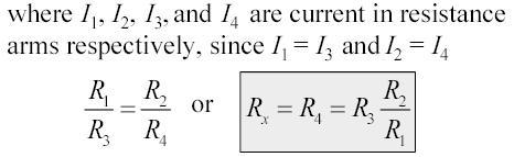
96 89
97 5.6 Kelvin s double bridge It is suitable for moderate resistance values: 1 ohm to ohm. Fig. 5.8 Kelvin s Double Bridge 5.7 Maxwell bridge Definition A Maxwell Bridge (in long form, a Maxwell-Wien bridge) is a type of Wheatstone bridge used to measure an unknown inductance (usually of low Q value) in terms of calibrated resistance and capacitance. It is a real product bridge. The Maxwell Bridge is used to measure unknown inductance in terms of calibrated resistance and capacitance. Calibration-grade inductors are more difficult to manufacture than capacitors of similar precision, and so the use of a simple "symmetrical" inductance bridge is not always practical. 90
98 Fig. 5.9 Maxwell Bridge Explanation With reference to the picture, in a typical application R1 and R4 are known fixed entities, and R2 and C2 are known variable entities. R2 and C2 are adjusted until the bridge is balanced.r3 and L3 can then be calculated based on the values of the other components: As shown in figure above, one arm of the Maxwell bridge consists of a capacitor in parallel with a resistor (C1 and R2) and another arm consists of an inductor L1 in series with a resistor (L1 and R4) The other two arms just consist of a resistor each (R1 and R3). The values of R1 and R3 are known, and R2 and C1 are both adjustable. The unknown values are those of L1 and R4. Like other bridge circuits, the measuring ability of a Maxwell Bridge depends on 'Balancing' the circuit. Balancing the circuit in Figure 1 means adjusting C1 and R2 until the current through the bridge between points A and B becomes zero. This happens when the voltages at points A and B are equal. Mathematically, Z1 = R2 + 1/ (2πfC1); while Z2 = R4 + 2πfL1. (R2 + 1/ (2πfC1)) / R1 = R3 / [R4 + 2πfL1]; or R1R3 = [R2 + 1/ (2πfC1)] [R4 + 2πfL1] To avoid the difficulties associated with determining the precise value of a variable capacitance, sometimes a fixed-value capacitor will be installed and more than one resistor will be made variable. The additional complexity of using a Maxwell bridge over simpler bridge types is warranted in circumstances where either the mutual inductance between the load and the known bridge entities, or stray electromagnetic interference, distorts the measurement results. The capacitive reactance in the bridge will exactly oppose the inductive reactance of the load when the bridge is balanced, allowing the load's resistance and reactance to be reliably determined. 91
99 Advantages: The frequency does not appear Wide range of inductance Disadvantages: Limited measurement It requires variable standard capacitor 5.8 Schering Bridge Definition Schering Bridge is a bridge circuit used for measuring an unknown electrical capacitance and its dissipation factor. The dissipation factor of a capacitor is the ratio of its resistance to its capacitive reactance. The Schering Bridge is basically a four arm alternating-current (AC) bridge circuit whose measurement depends on balancing the loads on its arms. Fig Schering Bridge Explanation In the Schering Bridge above, the resistance values of resistors R1 and R2 are known, while the resistance value of resistor R3 is unknown. The capacitance values of C1 and C2 are also known, while the capacitance of C3 is the value being measured. To measure R3 and C3, the values of C2 and R2 are fixed, while the values of R1 and C1 are adjusted until the current through the ammeter between points A and B becomes zero. This happens when the voltages at points A and B are equal, in which case the bridge is said to be 'balanced'. 92
100 When the bridge is balanced, Z1/C2 = R2/Z3, where Z1 is the impedance of R1 in parallel with C1 and Z3 is the impedance of R3 in series with C3. In an AC circuit that has a capacitor, the capacitor contributes a capacitive reactance to the impedance. Z1 = R1/[2πfC1((1/2πfC1) + R1)] = R1/(1 + 2πfC1R1) while Z3 =1/2πfC3 + R3. 2πfC2R1/ (1+2πfC1R1) = R2/(1/2πfC3 + R3); or 2πfC2 (1/2πfC3 + R3) = (R2/R1) (1+2πfC1R1); or C2/C3 + 2πfC2R3 = R2/R1 + 2πfC1R2. When the bridge is balanced, the negative and positive reactive components are equal and cancel out, so 2πfC2R3 = 2πfC1R2 or R3 = C1R2 / C2. Similarly, when the bridge is balanced, the purely resistive components are equal, so C2/C3 = R2/R1 or C3 = R1C2 / R2. Note that the balancing of a Schering Bridge is independent of frequency. Advantages: Balance equation is independent of frequency Used for measuring the insulating properties of electrical cables and equipments 5.9 Wien Bridge Definition A Wien bridge oscillator is a type of electronic oscillator that generates sine waves. It can generate a large range of frequencies. The circuit is based on an electrical network originally developed by Max Wien in Wien did not have a means of developing electronic gain so a workable oscillator could not be realized. The modern circuit is derived from William Hewlett's 1939 Stanford University master's degree thesis. Hewlett, along with David Packard co-founded Hewlett-Packard. Their first product was the HP 200A, a precision sine wave oscillator based on the Wien bridge. The 200A was one of the first instruments to produce such low distortion. Fig Wien Bridge 93
101 Amplitude stabilization: The key to Hewlett's low distortion oscillator is effective amplitude stabilization. The amplitude of electronic oscillators tends to increase until clipping or other gain limitation is reached. This leads to high harmonic distortion, which is often undesirable. Hewlett used an incandescent bulb as a positive temperature coefficient (PTC) thermistor in the oscillator feedback path to limit the gain. The resistance of light bulbs and similar heating elements increases as their temperature increases. If the oscillation frequency is significantly higher than the thermal time constant of the heating element, the radiated power is proportional to the oscillator power. Since heating elements are close to black body radiators, they follow the StefanBoltzmann law. The radiated power is proportional to T4, so resistance increases at a greater rate than amplitude. If the gain is inversely proportional to the oscillation amplitude, the oscillator gain stage reaches a steady state and operates as a near ideal class A amplifier, achieving very low distortion at the frequency of interest. At lower frequencies the time period of the oscillator approaches the thermal time constant of the thermistor element and the output distortion starts to rise significantly. Light bulbs have their disadvantages when used as gain control elements in Wien bridge oscillators, most notably a very high sensitivity to vibration due to the bulb's micro phonic nature amplitude modulating the oscillator output, and a limitation in high frequency response due to the inductive nature of the coiled filament. Modern Distortion as low as % (-100 db) can be achieved with only modest improvements to Hewlett's original circuit. Wien bridge oscillators that use thermistors also exhibit "amplitude bounce" when the oscillator frequency is changed. This is due to the low damping factor and long time constant of the crude control loop, and disturbances cause the output amplitude to exhibit a decaying sinusoidal response. This can be used as a rough figure of merit, as the greater the amplitude bounce after a disturbance, the lower the output distortion under steady state conditions. Advantages: Frequency sensitive Supply voltage is purely sinusoidal 5.10 Q-Meter Every inductor coil has a certain amount of resistance and the coil should have lowest possible resistance. The ratio of the inductive reactance to the effective resistance of the coil is called the quality factor or Q-factor of the coil. So Q = XL / R = ωl / R 94
102 A high value of Q is always desirable as it means high inductive reactance and low resistance. A low value of Q indicates that the resistance component is relatively high and so there is a comparatively large loss of power. The effective resistance of the coil differs from its dc resistance because of eddy current and skin effects and varies in a highly complex manner with the frequency. For this reason Q is rarely computed by determination of R and L. Fig Circuit Diagram One possible way for determination of Q is by using the inductance bridge but such bridge circuits are rarely capable of giving accurate measurements, when Q is high. So special meters are used for determination of Q accurately. The Q-meter is an instrument designed for the measurement of Q-factor of the coil as well as for the measurement of electrical properties of coils and capacitors. -This instrument operates on the principle of series resonance i.e. at resonate condition of an ac series circuit voltage across the capacitor is equal to the applied voltage times of Q of the circuit. If the voltage applied across the circuit is kept-constant then voltmeter connected across the capacitor can be calibrated to indicate Q directly. Circuit diagram of a Q-meter is shown is figure. A wide-range oscillator with frequency range from 50 khz to 50 MHz is used as a power supply to the circuit. The output of the oscillator is shorted by a low-value resistance, Rsh usually of the order of 0.02 ohm. So it introduces almost no resistance into the oscillatory circuit and represents a voltage source with a very small or of almost negligible internal resistance. The voltage across the low-value shunt resistance Rsh, V is measured by a thermo-couple meter and the voltage across the capacitor, Vc is measured by an electronic voltmeter. For carrying out the measurement, the unknown coil is connected to the test terminals of the instrument, and the circuit is tuned to resonance either by varying the frequency of the oscillator or by varying the resonating capacitor C. Readings of voltages across capacitor C and shunt resistance Rsh are obtained and Q-factor of the coil is determined as follows : By definition Q-factor of the coil, Q = XL / R And when the circuit is under resonance condition XL = XC Or IXL = IXC = VC And the voltage applied to the circuit. V = IR So, Q = XL / R = IXL / R = VC / V This Q-factor is called the circuit Q because this measurement includes the losses of the resonating capacitor, voltmeter and the shunt resistor Rsh. So, the actual Q-factor of the coil will be somewhat greater 95
103 than the calculated Q-factor. This difference is usually very small and maybe neglected except when the resistance of the coil under test is relatively small in comparison to the shunt resistance Rsh. The inductance of the coil can also be computed from the known values of frequency f and resonating capacitor C as follows. At resonance, XL= XC or 2πfL = 1/2πfC or L = 1/ (2πf)2 Henry. GLOSSARY 1. MMF: MMF is the work done in moving a unit magnetic pole once around the magnetic circuit. 2 Magnetic field intensity: It is the MMF per unit length. 3.Electromechanical energy conversion: It occurs through the medium of the magnetic stored energy. 4.Critical field resistance: the resistance of the field circuit which will cause the shunt generator just to build up its emf at a specified field. 5.Geometric neutral axis (GNA): GNA is the axis which is situated geometrically or physically in the mid way between adjacent main poles. 6.Magnetic neutral axis (MNA): MNA is the axis which passes through the zero crossing of the resultant magnetic field waveform in the air gap. 7. Slot pitch: It is the distance between the two coil sides of the same commutator Segments. 8. Pole pitch: It is the ratio of the total no. of armature coils to the total no of poles. 9.DC Generator: DC Generator converts mechanical energy into electrical energy. 10. Commutator: The Commutator converts the alternating emf into unidirectional or direct emf. 11. DC Motor: D.C motor converts electrical energy into mechanical energy. 12. Torque: Torque is nothing but turning or twisting force about the axis. 13. Yoke: Protecting cover for the whole machine. 14. Interpoles: To improve Commutation. 15. Brushes: Collect current from the Commutator. 96
104 16. Self Excited: Field winding supplied from the armature itself. 17. Separately Excited: Field winding supplied from the separate supply. 18. EMF: Electro Motive force. 19. Back emf: In dc motor as the armature rotates inside magnetic flux an emf is induced in the armature conductor. This emf acts opposite to applied voltage known as back emf. 20. Self Inductance: The e.m.f induced in a coil due to change of flux in the same coil is known as self inductance. 21. Mutual Inductance: When two coils are kept closed together, due to the change in flux in one coil, an emf is induced in the another coil. 22. Accuracy: It is defined as the closeness with which the reading approaches an accepted standard value or ideal value or true value, of the variable being measured. 23. Linearity: The output of the transducer should be linearly proportional to the input quantity under measurement. It should have linear input - output characteristic. 24. Sensitivity: The sensitivity of the electrical transducer is defined as the electrical output obtained per unit change in the physical parameter of the input quantity. 25. Repeatability: The output of the transducer must be exactly the same, under same environmental conditions, when the same quantity is applied at the input repeatedly. 26. Dynamic Range: For a transducer, the operating range should be wide, so that it can be used over a wide range of measurement conditions. 27. Size: The transducer should have smallest possible size and shape with minimal weight and volume. This will make the measurement system very compact. 28. Speed of Response: It is the rapidity with which the transducer responds to changes in the measured quantity. The speed of response of the transducer should be as high as practicable. 29. Thermistor: is a type of resistor whose resistance is dependent on temperature, more so than in standard resistors. 30. LVDT: The linear variable differential transformer (LVDT) is a type of electrical transformer used for measuring linear displacement. 31. DVM: Digital Voltmeter (DVM) is an instrument to measure voltage. 97
105 32. DMM: Digital Multimeter (DMM) is an instrument to measure current, voltage and resistance. 33. DSO: Digital storage osilloscope (DSO) is an oscilloscope which stores and analyses the signal digitally. Two Marks Question & Answers UNIT I DC MACHINES PART A 1. Give advantages of three phase system over single phase system. Output of three phase machine is greater than single phase machine of same size. Three phase transmission system is more economical than single phase transmission system as less copper or aluminum is required. Three phase motors are normally self starting as against single phase motors. 2. Define stalling current of DC motor. (Nov/Dec 2007) Armature current, Ia = V - Eb/Ra At starting; Eb = 0. Stalling current = V/Ra 3. List the essential parts of a DC generator. (April/May 2008) Yoke, Poles, Brushes, Bearings, Shaft, Commutator, Pole shoes, commutator poles and armature windings. 4. Why yoke is required in a DC machine? (Nov/Dec 2005) It gives a protective cover to the machine and is a mechanical support for poles. 5. Why is the core of the armature laminated? Nov/Dec 2008) It helps in reducing eddy current losses. 6. Give the emf equation of a DC generator. (Nov/Dec 2005) Generated emf, E=PΦZN/60A Where, P- No. of poles, Φ flux per pole, Z - No. of conductors, N Speed of the armature and A - No. of parallel paths. 7. Give the type of armature windings used in DC machines. (April/May 2007) i. Wave winding 98
106 ii. Lap winding 8. Give the conditions to build up voltage in shunt generator. (Nov/Dec 2003) i. ii. iii. Residual magnetism should be there in the poles. The field winding should be connected with armature in proper way. The shunt field resistance should be less than the critical resistance under no load conditions. 9. List the main parts of stator of DC machine. (Nov/Dec 2006) i. Yoke ii. Field winding iii. Main poles iv. Commutator poles v. 10. What is the Commutator pitch of a 4 pole DC armature having 49 Commutator bars? (April/May 2006) Commutator pitch, yc = (No. of Commutator bars (+/-) 1)/No. of pairs of poles = 49(+/-) 1/2 = 24 or State Faraday s law of Electromagnetic induction. Whenever there is a change in the magnetic flux linked with a circuit, an emf is induced in the circuit. The magnitude of the induced emf is proportional to the rate of change of flux linkages. 12. Give an application of a differentially compounded generator. (Nov/Dec 2007) It is mainly used in arc welding where larger voltage drop is desirable with increasing in current. 13. Why series motor cannot be started without any load? (Nov/Dec 2007) In series motor, Φ is directly proportional to Ia under no load conditions, the armature current is extremely low and flux is also less. By N is inversely proportional to Φ, it is clear that; low Φ will result in extremely high motor speed. Hence series motor should always be started with some load on shaft. 14. What is the significance of back emf? (Nov/Dec 2012,May/June 2013) In motoring mode, armature induced emf is known as the back emf to stress the fact that it opposes armature emf. It plays the rule of a regulator. 99
107 15. Give the reason for high starting current in a DC motor. (May/June 2014) For large motors the armature resistance may be 0.01 pu or less. Thus in full voltage starting of a DC motor, the armature current can be several times (100 times of large motors) the rated value. 16. List the methods of speed control of DC shunt motor. (Nov/Dec 2009) i. Field control ii. Armature control iii. Armature resistance control iv. Ward-Leonard control v. 17. What are the different methods of excitation of generator? (Nov/Dec 2012) i. Separate excitation ii. Shunt excitation iii. Series excitation iv. Compound excitation v. 18. Define the term armature reaction? The interaction between the flux setup by the current carrying conductors with the main field flux is defined as armature reaction. 19. Define critical resistance of a DC shunt generator. It is defined as the resistance of the field circuit which will cause the shunt generator just to build up its emf at specified speed. 20. Mention the applications of DC series motor. (May/June 2013) i. Electric traction ii. Hoists iii. Cranes iv. Battery powered vehicles v. 21. What are the functions of interpoles and how are the interpole windings connected? (April/May 2010) Commutating winding is placed on interpoles to aid commutation process by inducing emf in commutating coils to cancel reactance emf. So interpoles are located the interpolar region along MNA of main poles in just above the brushes where the coils undergo commutation. 100
108 22. What is the importance of residual emf in self excited DC generator? The residual emf in self excited DC generator is used to develop emf in an armature. 23. A DC motor operates from a 240V supply; the armature resistance is 0.2 ohm. Determine the back emf when the armature current is 50A. Given Data: V = 240V, Ra = 0.2 ohm, Ia = 50A. Solution: Back emf, Eb=V-Ia x Ra = x 0.2 = 230V. 24. An 8 pole, wave wounded armature has 600 conductors and is driven at 625 rpm. If the flux per pole is 20 mwb, determine the generated emf. Given Data: P = 8, Z = 600, N = 625 rpm, Φ =20 mwb. Wave winding, A = 2 Solution: Generated emf, E=PΦZN/60A = 8 x 20 x 10-3 x 600 x 625/60 x 2 = 500V. UNIT II TRANSFORMERS PART A 1. Distinguish between core and shell type transformer. (April/May 2015) In core type, the windings surround the core considerably and in shell type the core surround the winding. 2. What is an ideal transformer and how does it differ from a practical transformer. (April/May 2015) An ideal transformer is one which does not involve any power loss and does not have any change in frequency. It decreases or increases the input voltage. Practical transformer is one which involves power loss and does not have any change in frequency. It decreases or increases the input voltage. 3. Define voltage regulation in a transformer. (May/June 2014) When a transformer is loaded with a constant primary voltage, the secondary voltage decreases for lagging Power factor load, and increases for leading power factor load because of its internal resistance and leakage reactance. The change in secondary terminal voltage from no load to full load expressed as a percentage of no loads or full load voltage is termed as regulation. 101
109 V 2 NL V 2 FL X 100 V 2 NL V 2 NL V 2 FL X 100 % regulation up = V 2 FL % regulation down = 4. Write down the emf equation of a transformer. (Nov/Dec 2012) Emf induced in primary coil E1 = 4.44 fφ mn1 volt Emf induced in secondary coil E2 = 4.44fΦ mn2 volt Where f is the frequency of AC input Φ m is the maximum value of flux in the core N1, N2 are the number of primary and secondary turns. 5. Define a transformer. (Dec 2006) The transformer is a static piece of apparatus by means of which electrical power is transformed from one alternating current circuit to another with desired change in voltage and current without any change in the frequency. It works on the principle of mutual induction. 6. Why transformers are rated in kva? Copper loss of a transformer depends on current and iron loss on voltage. Hence total losses depend on Volt- Ampere and not on the power factor. That is why the rating of transformers is in kva and not in kw. 7. Why the core of a transformer is is laminated? (Dec 2006) The purpose of laminating the core in a transformer is to reduce eddy current loss. 8. Draw the equivalent circuit of a transformer. 9. An 1100/400 V, 50 Hz single phase transformer has 100 turns on the secondary winding. Calculate the number of turns on its primary. We know V1 / V2 = k = N2 / N1 Substituting 400/1100 = 100/N1 102
110 N1 = 100/400 x 1100 = 275 turns. 10. What are the advantages of a transformer? Less I2R loss in the transmission line Less voltage drop in the line Efficiency of the transmission line is increased Volume of the conductor required is less. 11. Define voltage transformation ratio of transformer. (Nov/Dec 2012) The ratio of secondary induced emf to primary induced emf is called as voltage regulation ratio devoted by K. E2 N 2 K E1 N1 12. Draw the no load phasor diagram of a transformer. (Nov/Dec 2014) 13. Define all day efficiency. All day efficiency is the ratio energy (in kwh) delivered in a 24 hours period to the energy (in kwh) input for the same length of time. All day efficiency = Output in kwh/input in kwh (for 24 hrs) 14. Give the factors that determine the thickness of the lamination or stampings. (Jan 2007) i. ii. Iron loss Frequency 15. What are the properties of ideal transformer? (Dec 2005) It has no loss ii) Its winding has zero resistance. iii) Leakage flux is zero i.e 100% flux produced by primary links with the secondary 103
111 iv) Permeability of core is so high that negligible current is required to establish the flues is it. 16. What are the losses occurring in a transformer? i) Core losses ii) Copper losses 17. What is meant by core or iron losses? Core or iron losses are caused as the core gets subjected to an alternating flux. 18. What is meant by copper loss? The copper losses are due to the power wasted in the form of I2R due to the resistances of the primary and secondary windings. 19. What is meant by eddy current loss? The induced emf in the core tries to set up eddy currents in the core and hence responsible for the eddy current losses. 20. What is meant by hysteresis losses? Due to alternating flux set up in the magnetic core of the transformer, it undergoes a cycle of magnetization and demagnetization. Due to hysteresis effect there is loss of energy in this process which is called hysteresis loss. 21. What do you mean by step down transformer? (May/June 2013) If the secondary voltage is greater than primary value, the transformer is called step down transformer. 22. What are the functions of no-load current in a transformer? No-load current produces flux and supplies iron loss and copper loss on no-load. 23. What are the typical uses of auto transformer? To give small boost to a distribution cable to correct for the voltage drop As induction motor starters As furnace transformers As interconnecting transformers In control equipment for single phase and 3 phase elective locomotives 104
112 UNIT III INDUCTION MACHINES AND SYNCHRONOUS MACHINES PART A 1. Write the principle of operation of 3 phase induction motor. (Nov/Dec 2014) Induction motor works on the principle of faraday s laws of electromagnetic induction. It consists of stator and rotor windings. As these rotor windings or bars rotate within the magnetic field created by the stator magnetizing currents, voltages are induced in them. If the rotor were to stand still, then the induced voltages would be very similar to those induced in the stator windings. 2. Name the types of alternators. (Nov/Dec 2014) i. Salient pole or projected type ii. Cylindrical or non salient pole type 3. Compare slip ring and squirrel cage type rotor. (April/May 2015) Slip ring rotor: It has windings Squirrel cage rotor: It has copper bars and shorted through end rings 4. Mention the characteristic features of synchronous motor. (April/May 2015) 1. Synchronous motors are inherently not self starting. They require some external means to bring their speed close to synchronous speed to before they are synchronized. 2. The speed of operation of is in synchronism with the supply frequency and hence for constant supply frequency they behave as constant speed motor irrespective of load condition 3. This motor has the unique characteristics of operating under any electrical power factor. This makes it being used in electrical power factor improvement. 5. Mention some applications of synchronous motor. (May/June 2013) 1) used in machine tools 2) motor generator sets 3) synchronous clocks 4) belt driven reciprocating compressors 5) fans and blowers 6. Why synchronous motor is called so? (May/June 2013) Since the motor is always run with the synchronous speed. 105
113 7. Define slip of an induction motor. (May/June 2013) It is the ratio between slip speed to synchronous speed. Slip = (Ns-Nr)/Ns Where, Ns = Synchronous speed, Nr = Rotor speed 8. Name any four types of single phase induction motors based on method of starting. (May/June 2014) 1. Split phase induction motor. 2. Capacitor start induction motor. 3. Capacitor start and capacitor run motor. 4. Shaded pole induction motor. 9.Find the speed at which a 6 pole alternator is to be driven to obtain the frequency of emf induced to be 50 Hz. (May/June 2014) Speed, Ns=120f/p= 120X50/6= 1000 rpm. 10. Write down the relation between speed and frequency. (Nov/Dec 2012) Synchronous speed, Ns=120f/p Where, f = Frequency of supply in Hz, p = Number of poles in the stator. 11. What are the two types of 3 phase induction motor? There are two types of 3-phase induction motor based on the type of rotor used: (i) Squirrel cage induction motor. (ii) Slip ring induction motor. 12. What are the losses present in the Induction motor? 1. Stator copper loss. 2. Stator iron loss. 3. Rotor copper loss. 4. Windage loss & friction loss. 13. Why induction motors are called asynchronous? Because their rotors can never run with the synchronous speed. 14. What is synchronous speed? The speed at which the stator field rotates is called synchronous speed and it depends upon the frequency of supply and number of poles for which the stator is wound. Ns = synchronous speed in rpm. 106
114 = 120 f / p. f = frequency of supply. p = Number of poles in the stator. 15. What are the advantages of the slip-ring induction motor over squirrel cage Induction motor? Advantages: It is possible to speed control by regulating rotor resistance. High starting torque of 200 to 250% of full load voltage. Low starting current of the order of 250 to 300% of the full load current. Hence slip ring induction motors are used where one or more of the above requirements are to be met. 16. What is the function of slip-rings in 3-phase induction motor? The function of slip rings in the case of slip ring induction motor is to add external resistance in the Rotor circuit. If External resistances are added in the rotor circuit, it can be used for speed control operation. 17. What is the use of shading coil in the shaded pole motor? In shaded pole motors, the necessary phase-splitting is produced by induction. These motors have salient poles on stator and a squirrel cage type rotor. The poles are shaded i.e.; each pole carries a copper band one of its unequally divided part called shading band. When single phase A.C. supply is given to the stator winding, due to shading provided to the poles, a rotating magnetic field is generated. 18. What are the methods of starting of synchronous motor? The various methods of starting of synchronous motor are: i) Using pony motors ii) Using damper winding iii) As a slip ring induction motor iv) Using small D.C. machine coupled to it. 19. What is meant by synchronous motor? A motor having a speed directly proportional to the frequency of the AC power that operates it. 20. Write the use of damper winding? Damper windings help the synchronous motor to start on its own (self starting machine) by providing starting torque. 107
115 21. Compare salient pole rotor and cylindrical rotor. Salient Pole Synchronous Alternator: Salient pole Generators will have large diameter and short axial length Pole shoes cover 2/3 of the pitch Salient Poles are laminated in order to reduce eddy currents Non-Salient pole Synchronous Alternator: Non-Salient pole generators will have smaller diameter and longer axial length They are used for High speed operation (typically speed will be 1500 and 3000 rpm) Better in dynamic balancing because of absence of salient poles. UNIT IV BASICS OF MEASUREMENT AND INSTRUMENTATION PART A 1. What are the basic elements of a generalized measurement system? Primary sensing element which is generally a transducer. Data conditioning element which further consists of variable conversion element and variable manipulation element. Data transmission and presentation elements which include data transmission system and data display system. 2. List any four Static characteristics of a measuring system. Accuracy, Precision, Error, Resolution, Stability, Linearity etc. 3. Define the term Accuracy. The accuracy is defined as the degree of closeness with which the instrument reading approaches the true value of the quantity to be measured. It indicates the ability of an instrument to indicate the true value of the quantity. 4. What is an Error? (May/June 2014, Nov/Dec 2014) The algebraic difference between the indicated value and the true value of the quantity to be measured is called an error. 5. What is calibration? Calibration is the process of making an adjustment or making a scale so that the readings of an instrument agree with the accepted value and the certified standard. 108
116 6. What is exact difference between accuracy and Precision? Accuracy indicates how far the measured value is close to the true value while precision indicates how for a particular measured value is from the average of readings taken. Thus precision is not related to true value of the parameter to be measured. 7. Define the term Precision. It is the Measure of consistency or repeatability of measurements. It denotes the amount by which the individual readings are departed about the average of number of readings. 8. Mention the basic requirements of measurement. The standard used for comparison purpose must be accurately defined and Should be commonly accepted. The apparatus used and the method adopted must be provable. 9. What is a transducer? (Nov/Dec 2014) It is device that receives energy from one system and transmits it to another, often in a different form. 10. Explain the function of measurement system. The measurement system consists of a transducing element which converts the quantity to be measured in an analogous form. The analogous signal is then processed by some intermediate means and is then fed to the end device which presents the results of the measurement. 11. Give the applications of measurement systems. The instruments and measurement systems are sued for Monitoring of processes and operations. Control of processes and operations. Experimental engineering analysis. 12. Define static characteristics. Static characteristics are the set of rules or criteria that is defined for those instruments that varies very slowly with time or remains a constant. 13. Define Dynamic characteristics. Dynamic characteristics are the set of rules or criteria that is defined for those instruments that varies very rapidly with time. 109
117 14. What are the various Dynamic characteristics? Various Dynamic characteristics are Fidelity Speed of Response Time Delay Lag Dynamic error 15. State the advantages of Maxwell-wein bridge. The balance equation is independent of frequency and therefore more accurate. 16. State the disadvantage of Maxwell-wein bridge. This method needs a standard variable capacitor. Variable Capacitor is costliest. UNIT V ANALOG AND DIGITAL INSTRUMENTS PART A 1. What is meant by Q-factor? Q-factor is known as the quality factor. It is used to measure the quality factor of the coils such as inductors, Capacitors etc.. 2. What is meant by Q-meter? Q-meter is generally used to measure the Q-factor of the coil. 3. What are the various types of storage oscilloscopes? The various types of storage oscilloscopes are Analog storage oscilloscope Mesh storage oscilloscope Bistable phosphor storage oscilloscope Digital storage oscilloscope 4. What is the DSO? DSO is known as digital storage oscilloscope, it is used for storing the waveform in a digital form. It consists of a sample and hold circuit, control logic and an A/D converter the waveform can be stored in a buffer amplifier. 110
118 5. What are the various types of Bridges? Different types of bridges are shown below. 6. How low resistance is measured? (a) De Sauty sbridge (b) Maxwell s bridge (c) Kelvin's double bridge (d) Wien bridge 7. What are the different types DVM? (April/May 2011) (a) Ramp type DVM (b) Dual slope type integrating type (voltage to time) (c) Integrating type DVM (voltage to frequency) (d) Successive approximation type (SAR) 8. What short notes on DVM? (May/June 2013) DVM are measuring instruments that convert analog voltage to signals in to digital or numeric readout. 9. Write the working principle of Q-meter. (Nov/Dec 2014) The principle of Q-meter is based on series resonance. The voltage drop across the inductor or capacitor is Q times the applied voltage. 10. What are the advantages of digital instruments? Readings speed is very high due to digital display. They can be programmed and well suited for computerized control. 111
119 Important Question Bank UNIT I DC MACHINES PART A 1. State Faraday s law of Electromagnetic induction and Lenz law. 2. Mention the following functions in DC Machine (i) Commutator (ii) Brushes (iii) Yoke (iv) Field coils. 3. What are the main constructional elements of a DC Machine? 4. What is meant by excitation of dc machine? What are the different methods for the excitation of DC Machine? 5. What are the necessary conditions for the generators to be self excited? 6. Mention any 2-popular methods for the speed control of DC Shunt motor. 7. What is meant by motor? How the Faraday s Left hand rule is used explain it. 8. Define critical resistance of a dc generator? 9. List the different method of speed control of DC Shunt motor? 10. In speed control of DC Shunt Motor how the armature control method is distinguished with field control method. 11. What are the different techniques used for the speed control of DC Series Motor? 12. Write the formulae for voltage equation of a DC Motor. 13. What is meant by armature reaction? 14. Write the formulae for generated emf of a Generator. 15. State two applications of DC shunt motor and series motor. 16. What is the significance of back emf Motor? 17. List the different variable and constant losses in electrical machine. 18. What is the basic principle of a DC Generator? How the Faraday s Right Hand rule is implemented explain it. 19. Draw the mechanical characteristics of DC Series and DC Shunt Motor. 20. Explain the circuit for Star connection and Delta connection. PART B 1. With a neat sketch, explain the construction and working of DC Motor and explain each parts. 2. What is meant by DC Generator? Explain the theory and principle of operation and working of DC Generator. 3. Obtain the mathematical expression for the Generated EMF or EMF Equation of a Generator. 4. Calculate the emf generated by 4-pole wave wound generator having 65 slots with 12 conductors per slot when driven at 1200 rpm. The flux per pole is 0.02 Weber. 5. How the DC Motor can be classified and also explain the following characteristics (i)no Load Saturation characteristics (ii) Internal or Total Characteristics (iii) External Characteristics. 6. Explain the following methods for speed control of DC Motor (i) Armature Control Method (ii) Field Control Method. 7. A 250 V Shunt motor takes the total current of 20 A. The shunt field and armature resistances of 200 ohm and 0.3 ohm respectively. Determine (i) Value of back emf (ii) Gross mechanical power in armature. 8. Explain the different techniques for the speed control of DC Series Motor. 112
120 9. Explain the following characteristics (i) Speed versus Torque (ii) Torque versus Current (iii) Speed versus Current for the following motors DC Series, Shunt and Compound Motor. 10. The armature of a 6-pole, 600 rpm lap wound generator has 90 slots. If each coil has 4-turns. Calculate the flux per pole required to generate emf of 288 Volts. 11. A 4 pole d.c shunt generator with a wave wound armature has to supply a load of 500 lamps each of 100W at 250 V. allowing 10V for the voltage drop in the connecting leads between the generator and the load and drop of 1 voltage per brush, calculate the speed at which the generator should be driven. The flux per pole is 30mW and armature & shunt field resistances are respectively 0.05Ω & 65Ω. The number of armature conductor is A 220V DC shunt motor having an armature resistance of 0.25Ω carries an armature current of 50A & runs at 600 rpm. If the flux is reduced by 10% by field regulator, find the speed assuming low torque remains the same. UNIT II TRANSFORMER PART A 1. What is meant by a transformer? How the Faraday s law of Electromagnetic induction is applicable. 2. What are the main parts of a transformer? Explain the following elements (i) Primary winding (ii) Secondary winding (iii) Laminated iron core. 3. What is the purpose of laminating the core in a transformer? 4. Write the emf equation of the transformer. Define the term (i) Voltage Transformation Ratio. How it is applicable for Step up and Step down Transformer. 5. Distinguish the following types of transformer (i) Core type transformer (ii) Shell type transformer. 6. Explain the following parts in transformer (i) Magnetic part (ii) Electrical part (iii) Insulating part (iv) Cooling part. 7. How the step up transformer is distinguished with step down transformer? 8. Explain the term of transformer under no load condition with phasor diagram and output equation 9. What is meant by leakage flux? 10. Draw the equivalent circuit of a transformer and also write final output equation. 11. When the load current of a transformer increases how does the input current increases to meet with the new condition? 12. Write the formulae for Regulation of a transformer and explain it. 13. Define the term (i) Efficiency (ii) All Day Efficiency of a transformer. 14. What is meant by auto transformer? 15. In auto transformer how the step up and step down transformer can be obtained and also explain through turn ratio. 16. Explain the different losses occur in transformer (i) Core or Iron Loss (ii) Copper Loss. 17. Write the formulae for (i) Regulation (ii) Maximum Efficiency of the transformer 18. What are the advantages and applications of auto transformer? 19. How does the change in frequency affect the change in temperature? 20. Mention the properties of oil used in the transformer? 113
121 PART B 1. Draw the circuit diagram for single phase transformer and also explain the principle, construction, working of it. 2. Obtain the mathematical EMF Equation of a transformer and explain each terms. 3. Draw the circuit diagram of transformer and also obtain the equivalent circuit and mathematical expression for a transformer. 4. Explain the transformer phasor diagram under (i) No Load Condition (ii) On Load Condition. 5. What are the losses in a transformer? Derive the condition for maximum efficiency? 6. Explain with the help of circuit diagram how are (i) efficiency and (ii) regulation of single phase transformer predetermined by conducting open circuit and short circuit test? 7. What is meant by auto transformer? Explain the principle, construction, working of a auto transformer. And also explain (i) Step up auto transformer (ii) Step down auto transformer. 8. Draw the approximate equivalent circuit of single phase transformer and identify the various parameters? 9. Describe the tests to determine and explain how the regulation of the transformer is determined form the diagram. 10. A single phase 2200/250V, 50Hz transformer has a net core area of 36 cm2 and a maximum flux density of 6 Wb/m2. Calculate the number of turns of primary and secondary. 11. The no load current of a transformer is 5A at 0.3 power factor lagging & supplied at 2.30V,50 Hz. The number of turns on the primary winding is 200. Calculate (a) maximum value of flux in the core. (b) the core losses (c) magnetizing current. 12. A single-phase transformer with a ratio of 6600/600 V as a load impedance of (4+j3)Ω connected across the terminals of low voltage winding. Calculate the KW delivered to the load.neglacting losses in the transformer, find the current taken by it from the supply lines. UNIT III INDUCTION MACHINES AND SYNCHRONOUS MACHINES PART A 1. Mention some of the advantages of three phase induction motor? 2. Explain the stator and rotor construction and also mention different type in three phase induction motor? 3. Define the following terms (i)slip of the motor (ii) Synchronous speed of an induction motor? 4. Draw the Equivalent circuit of three phase induction motor. 5. Why the single phase induction motor is not self starting? How the single phase induction motor bring for self starting? 6. How the single phase induction motor can be classified into different types explain it. 7. Draw the diagram of a single phase induction and also mention its main parts. 8. Where are split phase motors used? 9. Explain the different types of rotor in three phase induction motor (i) Squirrel cage rotor (ii) Phase wound rotor. 10. What are the purposes that could be served by external resistor connected in the rotor Circuit of phase wound induction motor? 11. What is meant by double field revolving theory in single phase induction motor? 12. Explain the condition for maximum torque under running condition? 114
122 13. Mention any 2-starting methods in synchronous motor. 14. What is the use of shading coil in the shaded pole motor? 15. Draw the V-Curve for the Synchronous motor. 16. Write the following equation for synchronous motor (i) Synchronous speed (ii) Torque Equation. 17. What is meant by alternator? Mention the different types of alternator? 18. Define pitch factor and distribution factor as applied to an alternator? 19. What are the factors affecting alternator size? And also define voltage regulation of alternator? 20. What are the advantages of synchronous motor? PART B 1. Explain the principle, construction, working of an 3-phase induction motor. And also explain the following rotors (i) Squirrel cage Induction Motor (ii) Phase wound Rotor. Mention some of the advantages of three phase induction motor. 2. Explain the principle operation of three phase induction motor. And also explain the following terms (i) Frame (ii) Stator and Rotor Core (iii) Stator and Rotor Windings (iv) Air gap (v) Shaft and bearing (vi) Slip ring enclosure (vii) Fans. 3. Draw the Equivalent circuit diagram for a Three phase Induction Motor and at any slip. And also explain (i) Equivalent circuit of the rotor (ii)transformer Equivalent circuit for Induction Motor. 4. How the single phase induction motor bring of self starting. Explain the following types of Single Phase Induction Motor (i) Split phase Induction Motor (ii) Capacitor Induction Motor (iii) Shaded Pole Induction Motor. 5. Explain the Double revolving field theory how it is applicable for a Single phase Induction Motor. 6. With neat sketch, explain the principle, construction, working and types of a three phase alternator. 7. Explain the following terms in three phase alternator (i) Equation of induced emf (ii) Voltage Regulation (iii) Types. 8. What is meant by Synchronous motor? Obtain the formulae for Synchronous speed. And also explain the different methods for starting of synchronous motor. 9. In synchronous Motor explain the following terms (i) Torque Equation (ii) V-Curve Characteristics. 10. A 50 Hz, 4-pole,3-phase induction motor has a rotor current of frequency 2 Hz. Determine (i) Slip (ii) Speed of Motor. 11. The input powr to a 6 pole,3 phase,50 HZ Induction motor is 42 KW;the speed is 970 r.p.m.the stator losses are 1.2KW and the friction and windage losse 1.8 kw.find (i)the rotor cu loss(ii)the efficiency of the motor. 12. A 1500KVA,6.6KV,3 phase, star connected alternator has a resistance of 0.5Ω/phase and a synchrouns reactance of 5Ω/phase. find its voltage regulation for (i) unity p.f(ii) 0.8 p.f lagging. 115
123 UNIT IV BASICS OF MEASUREMENTS AND INSTRUMENTATION PART A 1. What is meant by static characteristics in measurement system? Mention any 4-static characteristics of instrumentation. 2. Define the following static characteristics (i) Accuracy (ii) Precision (iii) Span (iv) Static sensitivity. 3. What is meant by dynamic characteristics in measurement system? Mention any 4-dynamic characteristics of measurement system. 4. What is meant by error? Mention the different types of errors produced in measurement system. 5. How the active transducer is distinguished with passive transducer? Give examples for each. 6. What is meant by analog and digital transducer? Give examples for each. 7. How the primary transducer is distinguished with secondary transducer? Give examples for each. 8. What is meant by variable resistance type or potentiometer? How the potentiometer can be classified? 9. Draw the schematic diagram for translational type potentiometer and also write the mathematical expression for output voltage. 10. Mention the different materials used for potentiometer. 11. What is meant by strain gauge? And also define the term Piezo resistive effect. 12. What are the different materials used for the construction of strain gauges? And also write the formulae for gauge factor. 13. What is meant by semi conductor type strain gauges? Mention the different materials used for the construction and also write the advantages of it. 14. What is meant by thermistor? Why thermistor is said to be Negative Temperature Coefficient of Resistance (NTCR)? 15. What is meant by RTD? Write the mathematical expression for RTD? Why RTD is said to be Positive Temperature Coefficient of Resistance (PTCR)? 16. Draw the schematic diagram of parallel plate capacitor. And also write the mathematical expression for it. 17. Mention any 4-applications of capacitance type transducer. 18. What is meant by piezo electric effect? Give any 4-materials used for piezo electric effect. 19. What is meant by variable inductive transducer? Mention the different types of variable inductive transducer. 20. What is meant by Linear Variable Differential Transformer (LVDT)? Draw the schematic diagram of LVDT. And also write the output equation for (i) Null Position (ii) Left Position (iii) Zero Position. PART B 1. Explain the following characteristics of measurement system (i) Static Characteristics (ii) Dynamic Characteristics. 2. What is meant by error in measurement system? Explain the following types of errors (i) Gross Error (ii) Systematic Error (iii) Random Error. 116
124 3. Explain the following types of transducer (i) Active and Passive Transducer (ii) Primary and Secondary Transducer (iii) Analog and Digital Transducer (iv) Transducer and Inverse Transducer. 4. What is meant by variable resistance transducer or potentiometer? Explain the following types of potentiometer (i) Translational type Potentiometer (ii) Rotational type potentiometer (iii) Helical type potentiometer. And also write the advantages, disadvantages and applications of it. 5. What is meant by Piezo electric effect? Obtain the mathematical expression for gauge factor in strain gauge. Explain the different types of strain gauges (i) Wire wound type strain gauges (ii) Bonded metal foil strain gauges (iii) Thin film type of strain gauges (iv) Semi conductor type strain gauges (v) Rosettes. And also write the applications of strain gauges. 6. Explain the principle, construction, working, mathematical expression of RTD. Also explain the following RTD Scheme (i) Two lead arrangement (ii) Three lead arrangement (iii) Four lead platinum thermometer. 7. Explain the principle, construction, working, mathematical expression of Thermistor. Also write the advantages, disadvantages and applications of it. 8. Explain the following types of capacitive type transducers (i) Parallel plate capacitor (ii) Cylindrical plate capacitor (iii) Capacitor type transducer as microphone. 9. What is meant by piezo electric effect? Mention any 4-materials used for piezo electric effect. Obtain the expression for output voltage and equivalent circuit of piezo electric crystal. And also write the advantages, disadvantages and applications of it. 10. What is meant by variable inductive transducer? Explain the following different types of variable inductive transducer (i) Variation of self inductance of the coil (ii) Variation of mutual inductance of the coil (iii) Production of eddy current. 11. Explain the construction, working and characteristics of LVDT. And also write the advantages, disadvantages and applications of it. 12. Explain the construction, working and characteristics of RVDT. UNIT V ANALOG AND DIGITAL INSTRUMENTS PART A 1. What are the advantages of digital mode of operation compare with analog mode of operation. 2. What is meant by storage oscilloscope? Mention any 2-applications of storage oscilloscope. 3. Write some of the advantages of digital voltmeter compare with analog voltmeter. 4. How the analog instrument is distinguished with digital instruments explain it? 5. Mention any 4-different types of digital voltmeter. 6. Draw the block diagram of ramp type digital voltmeter. 7. What is digital multimeter? Mention the different quantities measured by digital multimeter. 8. Write some of the advantages of digital multimeter. 9. How the resistance can be classified into low, medium and high value? And also Mention the different instruments used for measure purpose. 10. What is meant by bridges? Mention any 2-examples for source and detectors for bridges. 11. Draw the general circuit diagram for AC Bridge. Also write the general equation for magnitude and impedance of it 12. Mention any 4-examples for AC bridges for measurement of different quantities. 117
125 13. Draw the circuit diagram of wheat stone bridge and also write the output equations for it. 14. What is the use of Kelvin s double bridge? Draw the circuit diagram of Kelvin s double bridge. And also write the final equation for it. 15. What is the use of Anderson s bridge? Draw the circuit diagram of Anderson s bridge and also write the final value of R1 and L What is the use of Schering Bridge? Draw the circuit diagram of Schering Bridge and also write the value of r1 and C What is the use of Wien s bridge? Draw the circuit diagram of Wein s bridge and also write the formula for frequency. 18. Draw the series RLC circuit for the formation of Q-meter. 19. In Q-Meter which condition the resonance occurs and also write the formula for resonant frequency 20. Write the formula for Q-factor. Mention any 4-applications of Q-Meter. PART B 1. How the analog instrument is distinguished with digital instruments explain it. 2. Explain the following types of Digital voltmeter (i) Ramp type Digital Voltmeter (ii) Dual slope integrating type Digital Voltmeter. 3. Draw the block diagram and explain the following types of voltmeter (i) Successive approximation type DVM (ii) Potentiometric type DVM 4. Draw the block diagram of Digital Multimeter. How it can be used for the measurement of (i) DC Voltage (ii) AC Voltage (iii) DC Current (iv) Resistance. And also write the advantages of it. 5. Draw the schematic diagram of storage oscilloscope and explain each part. 6. Draw the circuit diagram of Wheat stone bridge. How it can be used for the measurement of medium value of resistance. 7. Draw the circuit diagram of Kelvin s double bridge. How it can be used for the measurement of low value resistance. 8. Draw the circuit diagram of Anderson s bridge. How it can be used to measure the value of self inductance explain it. 9. Draw the circuit diagram of Schering Bridge. How it can be used to measure the value of capacitance explain it. 10. Draw the circuit diagram of Wien s bridge. How it can be used to measure the value of frequency explain it. 11. What is meant by Q-factor of a coil? Draw the circuit diagram of Q-meter. How it can be used to measure the value of Q-factor of the coil explain it. 12. How the effective resistance at high frequency can be measured by Q-Meter explain it. 118

126 University Question Bank 119
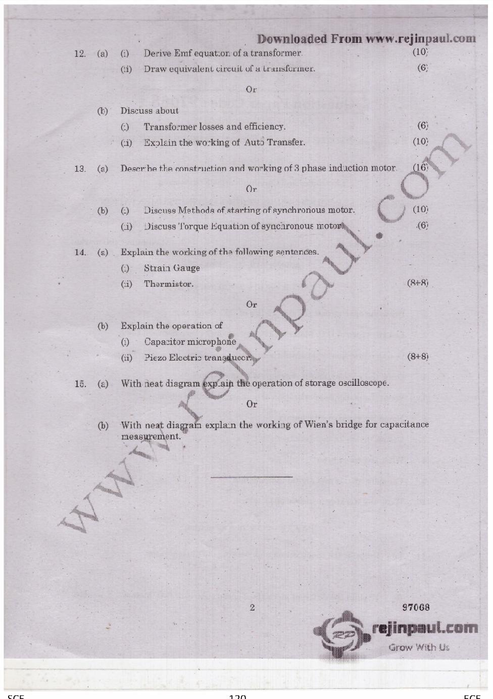
127 120
128 121
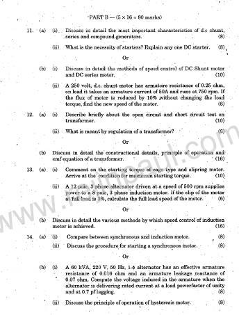
129 122
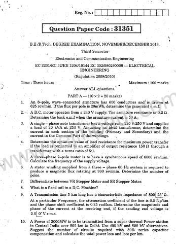
130 123
131 124
132 125
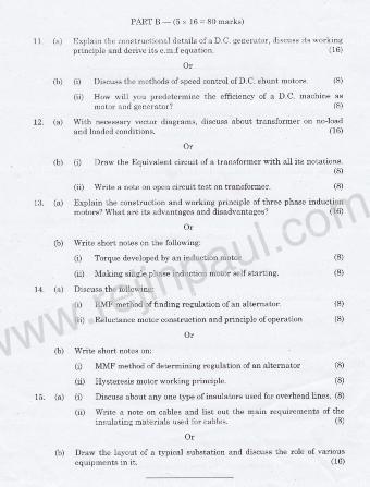
133 126
PART A. 1. List the types of DC Motors. Give any difference between them. BTL 1 Remembering
 UNIT I DC MACHINES Three phase circuits, a review. Construction of DC machines Theory of operation of DC generators Characteristics of DC generators Operating principle of DC motors Types of DC motors
 VIDYARTHIPLUS - ANNA UNIVERSITY ONLINE STUDENTS COMMUNITY UNIT 1 DC MACHINES PART A 1. State Faraday s law of Electro magnetic induction and Lenz law. 2. Mention the following functions in DC Machine (i)
1. Explain in detail the constructional details and working of DC motor.
 DHANALAKSHMI SRINIVASAN INSTITUTE OF RESEARCH AND TECHNOLOGY, PERAMBALUR DEPT OF ECE EC6352-ELECTRICAL ENGINEERING AND INSTRUMENTATION UNIT 1 PART B 1. Explain in detail the constructional details and
Module 1. Introduction. Version 2 EE IIT, Kharagpur
 Module 1 Introduction Lesson 1 Introducing the Course on Basic Electrical Contents 1 Introducing the course (Lesson-1) 4 Introduction... 4 Module-1 Introduction... 4 Module-2 D.C. circuits.. 4 Module-3
3. What is hysteresis loss? Also mention a method to minimize the loss. (N-11, N-12)
") DHANALAKSHMI COLLEGE OF ENGINEERING, CHENNAI DEPARTMENT OF ELECTRICAL AND ELECTRONICS ENGINEERING EE 6401 ELECTRICAL MACHINES I UNIT I : MAGNETIC CIRCUITS AND MAGNETIC MATERIALS Part A (2 Marks) 1. List
DHANALAKSHMI COLLEGE OF ENGINEERING, CHENNAI DEPARTMENT OF ELECTRICAL AND ELECTRONICS ENGINEERING EE 6401 ELECTRICAL MACHINES I UNIT I : MAGNETIC CIRCUITS AND MAGNETIC MATERIALS Part A (2 Marks) 1. List
SKP Engineering College
 SKP Engineering College Tiruvannamalai 606611 A Course Material on Electrical Engineering and Instrumentation By M. Thanigaivelraja / G. Nithiyanandham Assistant Professor Electrical and Electronics Engineering
VALLIAMMAI ENGINEERING COLLEGE
 VALLIAMMAI ENGINEERING COLLEGE SRM Nagar, Kattankulathur 603 203 DEPARTMENT OF ELECTRONICS AND INSTRUMENTATION ENGINEERING QUESTION BANK IV SEMESTER EI6402 ELECTRICAL MACHINES Regulation 2013 Academic
Transformers. gpmacademics.weebly.com
 TRANSFORMERS Syllabus: Principles of operation, Constructional Details, Losses and efficiency, Regulation of Transformer, Testing: OC & SC test. TRANSFORMER: It is a static device which transfers electric
MAHARASHTRA STATE BOARD OF TECHNICAL EDUCATION
 Important Instructions to examiners: 1) The answers should be examined by key words and not as word-to-word as given in the model answer scheme. 2) The model answer and the answer written by candidate
WELCOME TO THE LECTURE
 WLCOM TO TH LCTUR ON TRNFORMR Single Phase Transformer Three Phase Transformer Transformer transformer is a stationary electric machine which transfers electrical energy (power) from one voltage level
MAHARASHTRA STATE BOARD OF TECHNICAL EDUCATION
 Important Instructions to examiners: 1) The answers should be examined by key words and not as word-to-word as given in the model answer scheme. 2) The model answer and the answer written by candidate
PESIT Bangalore South Campus Hosur road, 1km before Electronic City, Bengaluru -100 Department of Electronics & Communication Engineering
 INTERNAL ASSESSMENT TEST 3 Date : 15/11/16 Marks: 0 Subject & Code: BASIC ELECTRICAL ENGINEERING -15ELE15 Sec : F,G,H,I,J,K Name of faculty : Mrs.Hema, Mrs.Dhanashree, Mr Nagendra, Mr.Prashanth Time :
Walchand Institute of Technology. Basic Electrical and Electronics Engineering. Transformer
 Walchand Institute of Technology Basic Electrical and Electronics Engineering Transformer 1. What is transformer? explain working principle of transformer. Electrical power transformer is a static device
SYNCHRONOUS MACHINES
 SYNCHRONOUS MACHINES The geometry of a synchronous machine is quite similar to that of the induction machine. The stator core and windings of a three-phase synchronous machine are practically identical
Hours / 100 Marks Seat No.
 17415 15162 3 Hours / 100 Seat No. Instructions (1) All Questions are Compulsory. (2) Answer each next main Question on a new page. (3) Illustrate your answers with neat sketches wherever necessary. (4)
Placement Paper For Electrical
 Placement Paper For Electrical Q.1 The two windings of a transformer is (A) conductively linked. (B) inductively linked. (C) not linked at all. (D) electrically linked. Ans : B Q.2 A salient pole synchronous
UNIVERSITY OF TECHNOLOGY By: Fadhil A. Hasan ELECTRICAL MACHINES
 UNIVERSITY OF TECHNOLOGY DEPARTMENT OF ELECTRICAL ENGINEERING Year: Second 2016-2017 By: Fadhil A. Hasan ELECTRICAL MACHINES І Module-II: AC Transformers o Single phase transformers o Three-phase transformers
Electrical Machines (EE-343) For TE (ELECTRICAL)
 For TE (ELECTRICAL)") PRACTICALWORKBOOK Electrical Machines (EE-343) For TE (ELECTRICAL) Name: Roll Number: Year: Batch: Section: Semester: Department: N.E.D University of Engineering &Technology, Karachi Electrical Machines
PRACTICALWORKBOOK Electrical Machines (EE-343) For TE (ELECTRICAL) Name: Roll Number: Year: Batch: Section: Semester: Department: N.E.D University of Engineering &Technology, Karachi Electrical Machines
1. A battery has an emf of 12.9 volts and supplies a current of 3.5 A. What is the resistance of the circuit?
 1. A battery has an emf of 12.9 volts and supplies a current of 3.5 A. What is the resistance of the circuit? (a) 3.5 Ω (b) 16.4 Ω (c) 3.69 Ω (d) 45.15 Ω 2. Sign convention used for potential is: (a) Rise
INSTITUTE OF AERONAUTICAL ENGINEERING (AUTONOMOUS) Dundigal, Hyderabad
 Dundigal, Hyderabad") INSTITUTE OF AERONAUTICAL ENGINEERING (AUTONOMOUS) Dundigal, Hyderabad - 500 043 CIVIL ENGINEERING ASSIGNMENT Name : Electrical and Electronics Engineering Code : A30203 Class : II B. Tech I Semester Branch
INSTITUTE OF AERONAUTICAL ENGINEERING (AUTONOMOUS) Dundigal, Hyderabad - 500 043 CIVIL ENGINEERING ASSIGNMENT Name : Electrical and Electronics Engineering Code : A30203 Class : II B. Tech I Semester Branch
INSTITUTE OF AERONAUTICAL ENGINEERING (Autonomous) Dundigal, Hyderabad
 Dundigal, Hyderabad") I INSTITUTE OF AERONAUTICAL ENGINEERING (Autonomous) Dundigal, Hyderabad-500043 CIVIL ENGINEERING TUTORIAL QUESTION BANK Course Name : BASIC ELECTRICAL AND ELECTRONICS ENGINEERING Course Code : AEE018
I INSTITUTE OF AERONAUTICAL ENGINEERING (Autonomous) Dundigal, Hyderabad-500043 CIVIL ENGINEERING TUTORIAL QUESTION BANK Course Name : BASIC ELECTRICAL AND ELECTRONICS ENGINEERING Course Code : AEE018
INSTITUTE OF AERONAUTICAL ENGINEERING Dundigal, Hyderabad
 Course Name Course Code Class Branch INSTITUTE OF AERONAUTICAL ENGINEERING Dundigal, Hyderabad -500 043 AERONAUTICAL ENGINEERING TUTORIAL QUESTION BANK : ELECTRICAL AND ELECTRONICS ENGINEERING : A40203
3.1.Introduction. Synchronous Machines
 3.1.Introduction Synchronous Machines A synchronous machine is an ac rotating machine whose speed under steady state condition is proportional to the frequency of the current in its armature. The magnetic
Aligarh College of Engineering & Technology (College Code: 109) Affiliated to UPTU, Approved by AICTE Electrical Engg.
 Affiliated to UPTU, Approved by AICTE Electrical Engg.") Aligarh College of Engineering & Technology (College Code: 19) Electrical Engg. (EE-11/21) Unit-I DC Network Theory 1. Distinguish the following terms: (a) Active and passive elements (b) Linearity and
Aligarh College of Engineering & Technology (College Code: 19) Electrical Engg. (EE-11/21) Unit-I DC Network Theory 1. Distinguish the following terms: (a) Active and passive elements (b) Linearity and
SHRI RAMSWAROOP MEMORIAL COLLEGE OF ENGG. & MANAGEMENT
 SHRI RAMSWAROOP MEMORIAL COLLEGE OF ENGG. & MANAGEMENT B.Tech. [SEM I (CE,EC,EE,EN)] QUIZ TEST-3 (Session: 2012-13) Time: 1 Hour ELECTRICAL ENGINEERING Max. Marks: 30 (EEE-101) Roll No. Academic/26 Refer/WI/ACAD/18
INSTITUTE OF AERONAUTICAL ENGINEERING (Autonomous) Dundigal, Hyderabad ELECTRICAL AND ELECTRONICS ENGINEERING
 Dundigal, Hyderabad ELECTRICAL AND ELECTRONICS ENGINEERING") Course Name Course Code Class Branch INSTITUTE OF AERONAUTICAL ENGINEERING (Autonomous) Dundigal, Hyderabad - 500 043 ELECTRICAL AND ELECTRONICS ENGINEERING QUESTION BANK : ELECRICAL MACHINES I : A40212
Course Name Course Code Class Branch INSTITUTE OF AERONAUTICAL ENGINEERING (Autonomous) Dundigal, Hyderabad - 500 043 ELECTRICAL AND ELECTRONICS ENGINEERING QUESTION BANK : ELECRICAL MACHINES I : A40212
INSTITUTE OF AERONAUTICAL ENGINEERING (Autonomous) Dundigal, Hyderabad
 Dundigal, Hyderabad") INSTITUTE OF AERONAUTICAL ENGINEERING (Autonomous) Dundigal, Hyderabad - 00 0 ELECTRICAL AND ELECTRONICS ENGINEERING QUESTION BANK Course Name Course Code Class Branch : ELECRICAL MACHINES - II : A0 :
INSTITUTE OF AERONAUTICAL ENGINEERING (Autonomous) Dundigal, Hyderabad - 00 0 ELECTRICAL AND ELECTRONICS ENGINEERING QUESTION BANK Course Name Course Code Class Branch : ELECRICAL MACHINES - II : A0 :
INSTITUTE OF AERONAUTICAL ENGINEERING (AUTONOMOUS)
") Name Code Class Branch INSTITUTE OF AERONAUTICAL ENGINEERING (AUTONOMOUS) Dundigal, Hyderabad -500 043 CIVIL ENGINEERING TUTORIAL QUESTION BANK : ELECTRICAL AND ELECTRONICS ENGINEERING : A30203 : II B.
Name Code Class Branch INSTITUTE OF AERONAUTICAL ENGINEERING (AUTONOMOUS) Dundigal, Hyderabad -500 043 CIVIL ENGINEERING TUTORIAL QUESTION BANK : ELECTRICAL AND ELECTRONICS ENGINEERING : A30203 : II B.
INSTITUTE OF AERONAUTICAL ENGINEERING (Autonomous) Dundigal, Hyderabad
 Dundigal, Hyderabad") INSTITUTE OF AERONAUTICAL ENGINEERING (Autonomous) Dundigal, Hyderabad - 00 03 ELECTRICAL AND ELECTRONICS ENGINEERING ASSIGNMENT Course Name : ELECRICAL MACHINES - II Course Code : A0 Class : II B.TECH-II
INSTITUTE OF AERONAUTICAL ENGINEERING (Autonomous) Dundigal, Hyderabad - 00 03 ELECTRICAL AND ELECTRONICS ENGINEERING ASSIGNMENT Course Name : ELECRICAL MACHINES - II Course Code : A0 Class : II B.TECH-II
Three-Phase Induction Motors. By Sintayehu Challa ECEg332:-Electrical Machine I
 Three-Phase Induction Motors 1 2 3 Classification of AC Machines 1. According to the type of current Single Phase and Three phase 2. According to Speed Constant Speed, Variable Speed and Adjustable Speed
Generalized Theory Of Electrical Machines
 Essentials of Rotating Electrical Machines Generalized Theory Of Electrical Machines All electrical machines are variations on a common set of fundamental principles, which apply alike to dc and ac types,
Reg. No. : BASIC ELECTRICAL TECHNOLOGY (ELE 101)
") Department of Electrical and Electronics Engineering Reg. No. : MNIPL INSTITUTE OF TECHNOLOGY, MNIPL ( Constituent Institute of Manipal University, Manipal) FIRST SEMESTER B.E. DEGREE MKEUP EXMINTION (REVISED
Department of Electrical and Electronics Engineering Reg. No. : MNIPL INSTITUTE OF TECHNOLOGY, MNIPL ( Constituent Institute of Manipal University, Manipal) FIRST SEMESTER B.E. DEGREE MKEUP EXMINTION (REVISED
INSTITUTE OF AERONAUTICAL ENGINEERING (Autonomous) Dundigal, Hyderabad
 Dundigal, Hyderabad") INSTITUTE OF AERONAUTICAL ENGINEERING (Autonomous) Dundigal, Hyderabad -00 03 ELECTRCIAL AND ELECTRONICS ENGINEERING TUTORIAL QUESTION BANK Course Name Course Code Class Branch : DC MACHINES AND TRANSFORMERS
INSTITUTE OF AERONAUTICAL ENGINEERING (Autonomous) Dundigal, Hyderabad -00 03 ELECTRCIAL AND ELECTRONICS ENGINEERING TUTORIAL QUESTION BANK Course Name Course Code Class Branch : DC MACHINES AND TRANSFORMERS
Introduction : Design detailed: DC Machines Calculation of Armature main Dimensions and flux for pole. Design of Armature Winding & Core.
 Introduction : Design detailed: DC Machines Calculation of Armature main Dimensions and flux for pole. Design of Armature Winding & Core. Design of Shunt Field & Series Field Windings. Design detailed:
MAHARASHTRA STATE BOARD OF TECHNICAL EDUCATION
 Important Instructions to examiners: 1) The answers should be examined by key words and not as word-to-word as given in the model answer scheme. 2) The model answer and the answer written by candidate
CHAPTER 2. Transformers. Dr Gamal Sowilam
 CHAPTER Transformers Dr Gamal Sowilam Introduction A transformer is a static machine. It is not an energy conversion device, it is indispensable in many energy conversion systems. A transformer essentially
Unit 3 Magnetism...21 Introduction The Natural Magnet Magnetic Polarities Magnetic Compass...21
 Chapter 1 Electrical Fundamentals Unit 1 Matter...3 Introduction...3 1.1 Matter...3 1.2 Atomic Theory...3 1.3 Law of Electrical Charges...4 1.4 Law of Atomic Charges...4 Negative Atomic Charge...4 Positive
Preface...x Chapter 1 Electrical Fundamentals
 Preface...x Chapter 1 Electrical Fundamentals Unit 1 Matter...3 Introduction...3 1.1 Matter...3 1.2 Atomic Theory...3 1.3 Law of Electrical Charges...4 1.4 Law of Atomic Charges...5 Negative Atomic Charge...5
EE 350: Electric Machinery Fundamentals
 EE 350: Electric Machinery Fundamentals Lecture Schedule See Time Table Course Type, Semester Fundamental Engineering, Fifth Credit Hours Three + One Pre-requisite Physics Instructor Dr. Muhammad Asghar
Code No: R Set No. 1
 Code No: R05220204 Set No. 1 II B.Tech II Semester Supplimentary Examinations, Aug/Sep 2007 ELECTRICAL MACHINES-II (Electrical & Electronic Engineering) Time: 3 hours Max Marks: 80 Answer any FIVE Questions
Single Phase induction Motor [1/Ch. 36]
![Single Phase induction Motor [1/Ch. 36]](/thumbs/88/116054273.jpg "Single Phase induction Motor [1/Ch. 36]") Single Phase induction Motor [1/h. 6] Equivalent ircuit of a Single-Phase nduction Motor without ore Loss [1/6.5/p.17] A single-phase motor may be looked upon as consisting of two motors, having a common
Single Phase induction Motor [1/h. 6] Equivalent ircuit of a Single-Phase nduction Motor without ore Loss [1/6.5/p.17] A single-phase motor may be looked upon as consisting of two motors, having a common
ELECTROMAGNETIC INDUCTION AND ALTERNATING CURRENT (Assignment)
") ELECTROMAGNETIC INDUCTION AND ALTERNATING CURRENT (Assignment) 1. In an A.C. circuit A ; the current leads the voltage by 30 0 and in circuit B, the current lags behind the voltage by 30 0. What is the
ELECTROMAGNETIC INDUCTION AND ALTERNATING CURRENT (Assignment) 1. In an A.C. circuit A ; the current leads the voltage by 30 0 and in circuit B, the current lags behind the voltage by 30 0. What is the
Transformer & Induction M/C
 UNIT- 2 SINGLE-PHASE TRANSFORMERS 1. Draw equivalent circuit of a single phase transformer referring the primary side quantities to secondary and explain? (July/Aug - 2012) (Dec 2012) (June/July 2014)
ELECTRICAL TECHNOLOGY
 ELECTRICAL TECHNOLOGY Subject Code: (EC303ES) Regulations : R6 JNTUH Class :II Year B.Tech ECE I Semester Department of Electronics and communication Engineering BHARAT INSTITUTE OF ENGINEERING AND TECHNOLOGY
EEE3441 Electrical Machines Department of Electrical Engineering. Lecture. Basic Operating Principles of Transformers
 Department of Electrical Engineering Lecture Basic Operating Principles of Transformers In this Lecture Basic operating principles of following transformers are introduced Single-phase Transformers Three-phase
Code No: R Set No. 1
 Code No: R05310204 Set No. 1 III B.Tech I Semester Regular Examinations, November 2007 ELECTRICAL MACHINES-III (Electrical & Electronic Engineering) Time: 3 hours Max Marks: 80 Answer any FIVE Questions
Bhoj Reddy Engineering College for Women, Hyderabad Department of Electronics and Communication Engineering Electrical and Electronics Instrumentation
 Bhoj Reddy Engineering College for Women, Hyderabad Department of Electronics and Communication Engineering Electrical and Electronics Instrumentation Academic Year: 2016-17 III B Tech II Semester Branch:
Bakiss Hiyana binti Abu Bakar JKE, POLISAS BHAB
 1 Bakiss Hiyana binti Abu Bakar JKE, POLISAS 1. Explain AC circuit concept and their analysis using AC circuit law. 2. Apply the knowledge of AC circuit in solving problem related to AC electrical circuit.
ENGINEERING ACADEMY X V
 1. Two incandescent bulbs of rating 230, 100 W and 230, 500 W are connected in parallel across the mains. As a result, what will happen? a) 100 W bulb will glow brighter b) 500 W bulb will glow brighter
APPLICATION NOTE - 018
 APPLICATION NOTE - 018 Power Transformers Background Power Transformers are used within an AC power distribution systems to increase or decrease the operating voltage to achieve the optimum transmission
MAHARASHTRA STATE BOARD OF TECHNICAL EDUCATION
 Important Instructions to examiners: 1. The answers should be examined by key words and not as word-to-word as given in the model answer scheme. 2. The model answer and the answer written by candidate
Inductance, capacitance and resistance
 Inductance, capacitance and resistance As previously discussed inductors and capacitors create loads on a circuit. This is called reactance. It varies depending on current and frequency. At no frequency,
UNIT II MEASUREMENT OF POWER & ENERGY
 UNIT II MEASUREMENT OF POWER & ENERGY Dynamometer type wattmeter works on a very simple principle which is stated as "when any current carrying conductor is placed inside a magnetic field, it experiences
THE SINUSOIDAL WAVEFORM
 Chapter 11 THE SINUSOIDAL WAVEFORM The sinusoidal waveform or sine wave is the fundamental type of alternating current (ac) and alternating voltage. It is also referred to as a sinusoidal wave or, simply,
Dhanalakshmi Srinivasan Institute of Technology, Samayapuram, Trichy. Cycle 2 EE6512 Electrical Machines II Lab Manual
 Cycle 2 EE652 Electrical Machines II Lab Manual CIRCUIT DIAGRAM FOR SLIP TEST 80V DC SUPPLY 350Ω, 2 A 3 Point Starter L F A NAME PLATE DETAILS: 3Ф alternator DC shunt motor FUSE RATING: Volts: Volts: 25%
Unit FE-5 Foundation Electricity: Electrical Machines
 Unit FE-5 Foundation Electricity: Electrical Machines What this unit is about Power networks consist of large number of interconnected hardware. This unit deals specifically with two types of hardware:
148 Electric Machines
 148 Electric Machines 3.1 The emf per turn for a single-phase 2200/220- V, 50-Hz transformer is approximately 12 V. Calculate (a) the number of primary and secondary turns, and (b) the net cross-sectional
Ac fundamentals and AC CIRCUITS. Q1. Explain and derive an expression for generation of AC quantity.
 Ac fundamentals and AC CIRCUITS Q1. Explain and derive an expression for generation of AC quantity. According to Faradays law of electromagnetic induction when a conductor is moving within a magnetic field,
CHAPTER 2. Basic Concepts, Three-Phase Review, and Per Unit
 CHAPTER 2 Basic Concepts, Three-Phase Review, and Per Unit 1 AC power versus DC power DC system: - Power delivered to the load does not fluctuate. - If the transmission line is long power is lost in the
REV NO EXPERIMENT NO 1 AIM: To perform open and short circuit tests on 1-phase transformer and to calculate efficiency. Apparatus required:
 KARNAL INSTITUTE OF TECHNOLOGY & MANAGEMENT KUNJPURA, KARNAL LAB MANUAL OF ------- SUBJECT CODE DATE OF ISSUE: SEMESTER: BRANCH: REV NO EXPERIMENT NO 1 AIM: To perform open and short circuit tests on 1-phase
TRANSFORMER THEORY. Mutual Induction
 Transformers Transformers are used extensively for AC power transmissions and for various control and indication circuits. Knowledge of the basic theory of how these components operate is necessary to
TRANSFORMERS PART A. 2. What is the turns ratio and transformer ratio of transformer? Turns ratio = N2/ N1 Transformer = E2/E1 = I1/ I2 =K
 UNIT II TRANSFORMERS PART A 1. Define a transformer? A transformer is a static device which changes the alternating voltage from one level to another. 2. What is the turns ratio and transformer ratio of
Types of Generators ACCORDING TO EXCITATION
 Types of Generators ACCORDING TO EXCITATION Separately Excited DC Generator A dc generator whose field magnet winding is supplied from an independent external d.c. source (e.g., a battery etc.) Separately
ELECTRICAL ENGINEERING ESE TOPIC WISE OBJECTIVE SOLVED PAPER-II
 ELECTRICAL ENGINEERING ESE TOPIC WISE OBJECTIVE SOLVED PAPER-II From (1992 2017) Office : F-126, (Lower Basement), Katwaria Sarai, New Delhi-110016 Phone : 011-26522064 Mobile : 8130909220, 9711853908
AC generator theory. Resources and methods for learning about these subjects (list a few here, in preparation for your research):
:") AC generator theory This worksheet and all related files are licensed under the Creative Commons Attribution License, version 1.0. To view a copy of this license, visit http://creativecommons.org/licenses/by/1.0/,
AC generator theory This worksheet and all related files are licensed under the Creative Commons Attribution License, version 1.0. To view a copy of this license, visit http://creativecommons.org/licenses/by/1.0/,
Generator Advanced Concepts
 Generator Advanced Concepts Common Topics, The Practical Side Machine Output Voltage Equation Pitch Harmonics Circulating Currents when Paralleling Reactances and Time Constants Three Generator Curves
15. the power factor of an a.c circuit is.5 what will be the phase difference between voltage and current in this
 1 1. In a series LCR circuit the voltage across inductor, a capacitor and a resistor are 30 V, 30 V and 60 V respectively. What is the phase difference between applied voltage and current in the circuit?
Synchronous Machines Study Material
 Synchronous machines: The machines generating alternating emf from the mechanical input are called alternators or synchronous generators. They are also known as AC generators. All modern power stations
CHIEF ENGINEER REG III/2 MARINE ELECTROTECHNOLOGY
 CHIEF ENGINEER REG III/2 MARINE ELECTROTECHNOLOGY LIST OF TOPICS 1 Electric Circuit Principles 2 Electronic Circuit Principles 3 Generation 4 Distribution 5 Utilisation The expected learning outcome is
GATE SOLVED PAPER - EE
 YEAR 03 Q. Leakage flux in an induction motor is (A) flux that leaks through the machine (B) flux that links both stator and rotor windings (C) flux that links none of the windings (D) flux that links
PHYS 1444 Section 003 Lecture #19
 PHYS 1444 Section 003 Lecture #19 Monday, Nov. 14, 2005 Electric Generators DC Generator Eddy Currents Transformer Mutual Inductance Today s homework is homework #10, due noon, next Tuesday!! 1 Announcements
DESIGN AND CONSTRUCTION OF 1500VA VARIABLE OUTPUT STEP DOWN TRANSFORMER
 DESIGN AND CONSTRUCTION OF 1500VA VARIABLE OUTPUT STEP DOWN TRANSFORMER OGUNDARE AYOADE B., OMOGOYE O. SAMUEL & OLUWASANYA OMOTAYO J. Department of Electrical/Electronic engineering, Lagos State Polytechnic,
DISCUSSION OF FUNDAMENTALS
 Unit 4 AC s UNIT OBJECTIVE After completing this unit, you will be able to demonstrate and explain the operation of ac induction motors using the Squirrel-Cage module and the Capacitor-Start Motor module.
PROBLEMS on Transformers
 PROBLEMS on Transformers (A) Simple Problems 1. A single-phase, 250-kVA, 11-kV/415-V, 50-Hz transformer has 80 turns on the secondary. Calculate (a) the approximate values of the primary and secondary
Alternating Current. Slide 1 / 69. Slide 2 / 69. Slide 3 / 69. Topics to be covered. Sources of Alternating EMF. Sources of alternating EMF
 Slide 1 / 69 lternating urrent Sources of alternating EMF Transformers ircuits and Impedance Topics to be covered Slide 2 / 69 LR Series ircuits Resonance in ircuit Oscillations Sources of lternating EMF
Alternating Current. Slide 2 / 69. Slide 1 / 69. Slide 3 / 69. Slide 4 / 69. Slide 6 / 69. Slide 5 / 69. Topics to be covered
 Slide 1 / 69 lternating urrent Sources of alternating EMF ircuits and Impedance Slide 2 / 69 Topics to be covered LR Series ircuits Resonance in ircuit Oscillations Slide 3 / 69 Sources of lternating EMF
Electrical Engineering / Electromagnetics
 Electrical Engineering / Electromagnetics. Plot voltage versus time and current versus time for the circuit with the following substitutions: A. esistor B. Capacitor C. Inductor t = 0 A/B/C A. I t t B.
THE UNIVERSITY OF BRITISH COLUMBIA. Department of Electrical and Computer Engineering. EECE 365: Applied Electronics and Electromechanics
 THE UNIVERSITY OF BRITISH COLUMBIA Department of Electrical and Computer Engineering EECE 365: Applied Electronics and Electromechanics Final Exam / Sample-Practice Exam Spring 2008 April 23 Topics Covered:
PHYS 1441 Section 001 Lecture #22 Wednesday, Nov. 29, 2017
 PHYS 1441 Section 001 Lecture #22 Chapter 29:EM Induction & Faraday s Law Transformer Electric Field Due to Changing Magnetic Flux Chapter 30: Inductance Mutual and Self Inductance Energy Stored in Magnetic
Transformers 21.1 INTRODUCTION 21.2 MUTUAL INDUCTANCE
 21 Transformers 21.1 INTRODUCTION Chapter 12 discussed the self-inductance of a coil. We shall now examine the mutual inductance that exists between coils of the same or different dimensions. Mutual inductance
COLLEGE OF ENGINEERING DEPARTMENT OF ELECTRICAL AND ELECTRONICS ENGINEERING ACADEMIC YEAR / EVEN SEMESTER QUESTION BANK
 KINGS COLLEGE OF ENGINEERING DEPARTMENT OF ELECTRICAL AND ELECTRONICS ENGINEERING ACADEMIC YEAR 2010-2011 / EVEN SEMESTER QUESTION BANK SUBJECT CODE & NAME: EE 1352 - ELECTRICAL MACHINE DESIGN YEAR / SEM
CHAPTER 2 D-Q AXES FLUX MEASUREMENT IN SYNCHRONOUS MACHINES
 22 CHAPTER 2 D-Q AXES FLUX MEASUREMENT IN SYNCHRONOUS MACHINES 2.1 INTRODUCTION For the accurate analysis of synchronous machines using the two axis frame models, the d-axis and q-axis magnetic characteristics
Module 9. DC Machines. Version 2 EE IIT, Kharagpur
 Module 9 DC Machines Lesson 35 Constructional Features of D.C Machines Contents 35 D.C Machines (Lesson-35) 4 35.1 Goals of the lesson. 4 35.2 Introduction 4 35.3 Constructional Features. 4 35.4 D.C machine
SECTION 4 TRANSFORMERS. Yilu (Ellen) Liu. Associate Professor Electrical Engineering Department Virginia Tech University
 Liu. Associate Professor Electrical Engineering Department Virginia Tech University") SECTION 4 TRANSFORMERS Yilu (Ellen) Liu Associate Professor Electrical Engineering Department Virginia Tech University Analysis of Transformer Turns Ratio......................... 4.2 Analysis of a Step-Up
SECTION 4 TRANSFORMERS Yilu (Ellen) Liu Associate Professor Electrical Engineering Department Virginia Tech University Analysis of Transformer Turns Ratio......................... 4.2 Analysis of a Step-Up
QUESTION BANK ETE (17331) CM/IF. Chapter1: DC Circuits
 CM/IF. Chapter1: DC Circuits") QUESTION BANK ETE (17331) CM/IF Chapter1: DC Circuits Q1. State & explain Ohms law. Also explain concept of series & parallel circuit with the help of diagram. 3M Q2. Find the value of resistor in fig.
QUESTION BANK ETE (17331) CM/IF Chapter1: DC Circuits Q1. State & explain Ohms law. Also explain concept of series & parallel circuit with the help of diagram. 3M Q2. Find the value of resistor in fig.
Hours / 100 Marks Seat No.
 17404 21314 3 Hours / 100 Seat No. Instructions (1) All Questions are Compulsory. (2) Answer each next main Question on a new page. (3) Illustrate your answers with neat sketches wherever necessary. (4)
Downloaded From All JNTU World
 Code: 9A02403 GENERATION OF ELECTRIC POWER 1 Discuss the advantages and disadvantages of a nuclear plant as compared to other conventional power plants. 2 Explain about: (a) Solar distillation. (b) Solar
CHAPTER 8: ELECTROMAGNETISM
 CHAPTER 8: ELECTROMAGNETISM 8.1: MAGNETIC EFFECT OF A CURRENT-CARRYING CONDUCTOR Electromagnets 1. Conductor is a material that can flow.. 2. Electromagnetism is the study of the relationship between.and..
AUTO-TRANSFORMER. This is having only one winding; part of this winding is common to both primary and secondary.
 AUTO-TRANSFORMER This is having only one winding; part of this winding is common to both primary and secondary. In 2-winding transformer both primary and secondary windings are electrically isolated, but
1. (a) Determine the value of Resistance R and current in each branch when the total current taken by the curcuit in figure 1a is 6 Amps.
 Determine the value of Resistance R and current in each branch when the total current taken by the curcuit in figure 1a is 6 Amps.") Code No: 07A3EC01 Set No. 1 II B.Tech I Semester Regular Examinations, November 2008 ELECTRICAL AND ELECTRONICS ENGINEERING ( Common to Civil Engineering, Mechanical Engineering, Mechatronics, Production
Code No: 07A3EC01 Set No. 1 II B.Tech I Semester Regular Examinations, November 2008 ELECTRICAL AND ELECTRONICS ENGINEERING ( Common to Civil Engineering, Mechanical Engineering, Mechatronics, Production
PHYS 1442 Section 004 Lecture #15
 PHYS 1442 Section 004 Lecture #15 Monday March 17, 2014 Dr. Andrew Brandt Chapter 21 Generator Transformer Inductance 3/17/2014 1 PHYS 1442-004, Dr. Andrew Brandt Announcements HW8 on Ch 21-22 will be
CHAPTER 2 STATE SPACE MODEL OF BLDC MOTOR
 29 CHAPTER 2 STATE SPACE MODEL OF BLDC MOTOR 2.1 INTRODUCTION Modelling and simulation have been an essential part of control system. The importance of modelling and simulation is increasing with the combination
Transformers. Dr. Gamal Sowilam
 Transformers Dr. Gamal Sowilam OBJECTIVES Become familiar with the flux linkages that exist between the coils of a transformer and how the voltages across the primary and secondary are established. Understand
CHAPTER 5 SYNCHRONOUS GENERATORS
 CHAPTER 5 SYNCHRONOUS GENERATORS Summary: 1. Synchronous Generator Construction 2. The Speed of Rotation of a Synchronous Generator 3. The Internal Generated Voltage of a Synchronous Generator 4. The Equivalent
Contents. About the Authors. Abbreviations and Symbols
 About the Authors Preface Abbreviations and Symbols xi xiii xv 1 Principal Laws and Methods in Electrical Machine Design 1 1.1 Electromagnetic Principles 1 1.2 Numerical Solution 9 1.3 The Most Common
Electrical Machines I : Transformers
 UNIT TRANSFORMERS PART A (Q&A) 1. What is step down transformer? The transformer used to step down the voltage from primary to secondary is called as step down transformer. (Ex: /11).. Draw the noload
1. If the flux associated with a coil varies at the rate of 1 weber/min,the induced emf is
 1. f the flux associated with a coil varies at the rate of 1 weber/min,the induced emf is 1 1. 1V 2. V 60 3. 60V 4. Zero 2. Lenz s law is the consequence of the law of conservation of 1. Charge 2. Mass
By Gill ( ) PDF created with FinePrint pdffactory trial version
 PDF created with FinePrint pdffactory trial version") By Gill (www.angelfire.com/al4/gill ) 1 Introduction One of the main reasons of adopting a.c. system instead of d.c. for generation, transmission and distribution of electrical power is that alternatin
By Gill (www.angelfire.com/al4/gill ) 1 Introduction One of the main reasons of adopting a.c. system instead of d.c. for generation, transmission and distribution of electrical power is that alternatin
Electrical Workstation Nvis 7089A
 All AC & DC Machines are optional Electrical Workstation offers an excellent approach to the teaching of Electrical Machines principles by introducing a unique modular designed control unit. It provides
Type of loads Active load torque: - Passive load torque :-
 Type of loads Active load torque: - Active torques continues to act in the same direction irrespective of the direction of the drive. e.g. gravitational force or deformation in elastic bodies. Passive