Course Plan Overview January 2015
|
|
|
- Sharleen Owen
- 5 years ago
- Views:
Transcription
1 Course Plan Overview January 2015 Page- 1
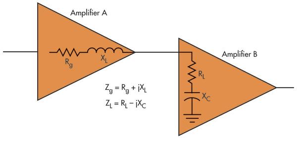
2 Impedance: Traditional electrical sense - as generalized resistance: Simple & Complex!! In the mechanical sense, or in a general sense with regard to other domains (e.g., fluid, thermal) as well depending on the type of signals involved. o A voltmeter can modify the currents (and voltages) in a circuit, and this concerns electrical resistance of a dc circuit or more generally, electrical impedance, when ac circuits are considered. o A heavy accelerometer will introduce an additional dynamic (mechanical) load, which will modify the actual acceleration at the monitoring location. This concerns mechanical impedance. o A thermocouple junction can modify the temperature that is measured as a result of the heat transfer into the junction. This concerns thermal impedance. Similarly we can define impedance for fluid systems, magnetic systems (reluctance), and so on. In general, impedance is defined as: = h h The across variable is measured across the two ends (ports) of a component, and the through variable transmits through the component unaltered. Examples of across variables are voltage, velocity, temperature, and pressure. Examples of through variables are current, force, heat transfer rate, and fluid flow rate. Even though electrical impedance is defined as voltage/current, which is consistent with the definition. Mechanical impedance, historically, has been defined as force/velocity, which is the inverse of the definition above. It is the mobility that is defined as velocity/force, and it should be interpreted as impedance in the general sense (i.e., generalized impedance), in our analysis. Cascade Connection of Devices: The output impedance: = (.., ) O/C voltage at output is the output voltage present when there is no current flowing at the output port. This is the case if the output port is not connected to a load (impedance). As soon as a load is connected at the output of the device, a current flows through it, and the output voltage drops to a value less than that of the open-circuit voltage. To measure the open-circuit voltage, the rated input voltage is applied at the input port and maintained constant, and the output voltage is measured using a voltmeter that has a high (input) impedance. To measure the short-circuit current, a very low-impedance ammeter is connected at the output port. The output impedance: = While Output terminals are maintained in O/C. Page- 2
3 and can be represented as shown in the diagram. Note that is the open-circuit output voltage. When a load is connected at the output port, the voltage across the load will be different from because this is caused by the presence of a current through Page- 3
 loading effect, and it has to be minimized. At the same time, adequate power and current would be needed for signal communication, conditioning, display, and so on.")
4 Loading Effect and Impedance Matching: When two electrical components are interconnected, current (and energy) flows between the two components and changes the original (unconnected) conditions. This is known as the (electrical) loading effect, and it has to be minimized. At the same time, adequate power and current would be needed for signal communication, conditioning, display, and so on. Both situations can be accommodated through proper matching of impedances when the two components are connected. Usually, an impedance-matching amplifier (i.e., an impedance transformer) would be needed between the two components. From the analysis given in the preceding section: The signal-conditioning circuitry should have a considerably large input impedance in comparison with the output impedance of the sensor transducer unit to reduce loading errors. Example: Problem is quite serious in measuring devices such as piezoelectric sensors, which have very high output impedances. A piezoelectric sensor is a device that uses the piezoelectric effect, to measure changes in pressure, acceleration, temperature, strain, or force by converting them to an electrical charge. In such cases, the input impedance of the signal-conditioning unit might be inadequate to reduce loading effects; Also, the output signal level of these high impedance sensors is quite low for signal transmission, processing, actuation, and control. The solution for this problem is to introduce several stages of amplifier circuitry between the output of the first hardware unit (e.g., sensor) and the input of the second hardware unit (e.g., data acquisition unit). The first stage of such an interfacing device is typically an impedance-matching amplifier that has high input impedance, low output impedance, and almost unity gain. The last stage is typically a stable high-gain amplifier stage to step up the signal level. Impedance-matching amplifiers are, in fact, op-amps with feedback. When connecting a device to a signal source, loading problems can be reduced by making sure that the device has a high input impedance. Unfortunately, this will also reduce the level (amplitude, power) of the signal received by the device. In fact, a high impedance device may reflect back some harmonics of the source signal. A termination resistance might be connected in parallel with the device to reduce this problem. Page- 4
5 In many data acquisition systems, output impedance of the output amplifier is made equal to the transmission line impedance. When maximum power amplification is desired, conjugate matching is recommended. In this case, input and output impedances of the matching amplifier are made equal to the complex conjugates of the source and load impedances, respectively. Page- 5

6 Using Complex Impedance: Page- 6
7 Modulation: Page- 7
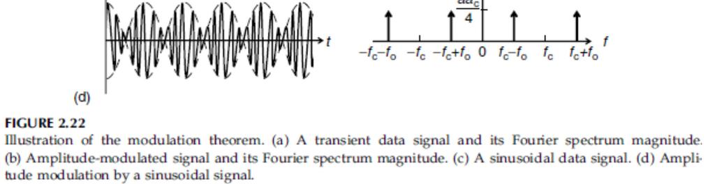
8 Page- 8
9 Modulation and De-Modulation: Consider the modulated signal above: Page- 9
10 Low Pass Filter with a cut-off: Page- 10
11 What if you applied a sine wave to this filter? Page- 11
12 What if you applied a Step Function to this filter? Page- 12
13 Bridge Circuits: Bridge circuits are used to make a form of measurement: Change in resistance Change in inductance Change in capacitance Oscillating frequency R 1 A Small i R 2 R 3 R 4 B - + v ref (Constant Voltage) + R L - v o Load (High) Page- 13
14 Continuing R 1 A Small i R 2 R 3 R 4 B - + v ref (Constant Voltage) + R L - v o Load (High) Page- 14
15 Example: Suppose that in Figure on the right, at first = = =. Now increase by, decrease by. This will represent two active elements that act in reverse, as in the case of two strain gage elements mounted on the top and the bottom surfaces of a beam in bending. Show that the bridge output is linear in in this case. R 1 A Small i R 2 R 3 R 4 B - + v ref (Constant Voltage) + R L - v o Load (High) Solution: Page- 15
16 [Grab your reader s attention with a great quote from the document or use this space to emphasize a key point. To place this text box anywhere on the page, just drag it.] Page- 16
. This is typically an instrumentation amplifier, which is essentially a sophisticated differential amplifier.")
17 Bridge Amplifiers: The output signal from a resistance bridge is usually very small in comparison to the reference signal, and it has to be amplified to increase its voltage level to a useful value (e.g., for use in system monitoring, data logging, or control). This is typically an instrumentation amplifier, which is essentially a sophisticated differential amplifier. The bridge amplifier is modeled as a simple gain, which multiplies the bridge output. Half-Bridge Circuits: A half bridge has only two arms. Output is tapped from the mid-point of these two arms. The ends of the two arms are excited by two voltages, one of which is positive and the other negative. Initially, the two arms have equal resistances so that nominally the bridge output is zero. One of the arms has the active element. Its change in resistance results in a nonzero output voltage. It is noted that the half-bridge circuit is somewhat similar to a potentiometer circuit (a voltage divider). Page- 17
18 The two bridge arms have resistances and, and the output amplifier uses a feedback resistance. To get the output equation, we use the two basic facts for an unsaturated opamp; 1. The voltages at the two input leads are equal (due to high gain), and 2. The current in either lead is zero (due to high input impedance). Hence, voltage at node A is zero and the current balance equation at node A is given by: Page- 18
19 Impedance Bridges: AC Bridge Contains four impedances:,, Owen Bridge: Page- 19
20 Wien Bridge Oscillator: Page- 20
21 Response parameters for time-domain specification of performance: Delay Time: This is usually defined as the time taken to reach 50% of the steady-state value for the first time. This parameter is also a measure of speed of response. Peak Time The time at the first peak of the device response is the peak time. This parameter also represents the speed of response of the device. Settling Time This is the time taken for the device response to settle down within a certain percentage (typically+2%) of the steady-state value. This parameter is related to the degree of damping present in the device as well as the degree of stability. Percentage Overshoot This is defined as, =100( 1)%, using the normalized-to-unity step response curve, where is the peak value. Percentage overshoot (PO) is a measure of damping or relative stability in the device. Simple Oscillator Model: Page- 21
22 Solution: Page- 22
23 Active Transducer: External power is required to operate active sensors/transducers, and they do not depend on their own power conversion characteristics for operation. A good example for an active device is a resistive transducer, such as a potentiometer, which depends on its power dissipation through a resistor to generate the output signal. Note that an active transducer requires a separate power source (power supply) for operation, Passive transducer: Draws its power from a measured signal (measurand). Since passive transducers derive their energy almost entirely from the measurand, they generally tend to distort (or load) the measured signal to a greater extent than an active transducer would. Precautions can be taken to reduce such loading effects. On the other hand, passive transducers are generally simple in design, more reliable, and less costly. For example, a piezoelectric charge generation is a passive process. But, a charge amplifier, which uses an auxiliary power source, would be needed by a piezoelectric device in order to condition the generated charge. Error Analysis: Error = (instrument reading) (true value) Measurement Accuracy: Determines the closeness of the measured value to the true value Instrument Accuracy: Related to the worst accuracy obtainable within the dynamic range of the instrument in a specific operating environment Page- 23
24 More discussion on Active and Passive Sensors: An active sensor is a sensing device that requires an external source of power to operate; active sensors contrast with passive sensors, which simply detect and respond to some type of input from the physical environment. In the context of remote sensing, an active sensor is a device with a transmitter that sends out a signal, light wavelength or electrons to be bounced off a target, with data gathered by the sensor upon their reflection. Active sensors are also widely used in manufacturing and networking environments for example to monitor industrial machines or data center infrastructure so anomalies can be detected and components can be repaired or replaced before they break and shut everything down. Examples of other active sensor-based technologies include: scanning electron microscopes, radar, GPS, x-ray, sonar, infrared and seismic. However, as can be the case with some sensors, seismic and infrared light sensors exist in both active and passive forms. A passive sensor is a device that detects and responds to some type of input from the physical environment. Passive sensor technologies gather target data through the detection of vibrations, light, radiation, heat or other phenomena occurring in the subject s environment. They contrast with active sensors, which include transmitters that send out a signal, a light wavelength or electrons to be bounced off the target, with data gathered by the sensor upon their reflection. Sensors can also be used in harsh environments and places inaccessible to people. Examples of passive sensor-based technologies include: Photographic, thermal, electric field sensing, chemical, infrared and seismic. However, as can be the case with some sensors, seismic and infrared light sensors exist in both active and passive forms. Page- 24
25 Linearizing Devices: Nonlinearity is present in any physical device, to varying levels. If the level of nonlinearity in a system (component, device, or equipment) can be neglected without exceeding the error tolerance, then the system can be assumed linear. Linear system is one that can be expressed as one or more linear differential equations. Note that the principle of superposition holds for linear systems. Nonlinearities in a system can appear in two forms: Dynamic manifestation of nonlinearities Static manifestation of nonlinearities Cases: The useful operating region of a system can exceed the frequency range where the frequency response function is flat. The operating response of such a system is said to be dynamic. o Examples include a typical control system (e.g., automobile, aircraft, milling machine, robot), actuator (e.g., hydraulic motor), and controller (e.g., proportional-integral-derivative or PID control circuitry). Nonlinearities of such systems can manifest themselves in a dynamic form such as the jump phenomenon (also known as the fold catastrophe), limit cycles, and frequency creation. Page- 25
26 Solutions for dynamic manifestations of nonlinearity: Design changes, extensive adjustments, or reduction of the operating signal levels and bandwidths would be necessary in general, to reduce or eliminate. Is that a good Solution? In many instances, such changes would not be practical, and we may have to somehow cope with the presence of these nonlinearities under dynamic conditions. Design changes might involve: o Replacing conventional gear drives by devices such as harmonic drives to reduce backlash. o Replacing nonlinear actuators by linear actuators, and o Using components that have negligible Coulomb friction and that make small motion excursions. What is Coulomb Friction? Coulomb friction is a simplified quantification of the friction force that exists between two dry surfaces in contact with each other. All friction calculations are approximations, and this measurement is dependent only on the fundamental principles of motion. It assumes that the contact surfaces are fairly uniform and that the coefficient of friction that must be overcome for motion to begin is wellestablished for the materials in contact. Page- 26
27 What about Static Manifestations: Making design changes and adjustments, as in the case of dynamic devices. Since the response is static, and since we normally deal with an available device (fixed design) whose internal hardware cannot be modified, We should consider ways of linearizing the input/output characteristic by modifying the output itself. o Linearization using digital software o Linearization using digital (logic) hardware o Linearization using analog circuitry In the software approach to linearization: o Output of the device is read into a digital processor with softwareprogrammable memory o And the output is modified according to the program instructions. In the hardware approach: o Output is read by a device with fixed logic circuitry for processing (modifying) the data. In the analog approach: o A linearizing circuit is directly connected at the output of the device, so that the output of the linearizing circuit is proportional to the input to the original device. Page- 27
28 Software based linearization: Assuming that the nonlinear relationship between the input and the output of a nonlinear device is known, the input can be computed for a known value of the output. In the software approach of linearization, a processor and memory that can be programmed using software (i.e., a digital computer) is used to compute the input using output data. Analysis: Flexible - Linearization algorithm can be modified (e.g., improved, changed) simply by modifying the program stored in the RAM. Highly complex nonlinearities can be handled by the software method. Relatively slow. Linearization by Hardware Logic: Hardware logic method: o Linearization algorithm is permanently implemented in the IC form using appropriate digital logic circuitry for data processing and memory elements (e.g., flip-flops). However, algorithm and numerical values of parameters (except input values) cannot be modified without redesigning the IC chip, because a hardware device typically does not have programmable memory. Difficult to implement very complex linearization algorithms Mass chip production, initial chip development cost? Testing for our needs only? Lack of Flexibility - A digital linearizing unit with a processor and a readonly memory (ROM), whose program cannot be modified, also lacks the flexibility of a programmable software device. Page- 28
29 Analog Linearizing Circuitry Three types of analog linearizing circuitry can be identified: Offsetting circuitry Circuitry that provides a proportional output Curve shapers Offsetting circuitry: An offset is a nonlinearity that can be easily removed using an analog device. Adding a dc offset of equal value to the response, in the opposite direction. Deliberate addition of an offset in this manner is known as offsetting. The associated removal of original offset is known as offset compensation. Example: o Results of ADC and DAC can be removed by analog offsetting. o Constant (dc) error components, such as steady-state errors in dynamic systems due to load changes, gain changes, and other disturbances, can be eliminated by offsetting. Easiest Approach - Use Summer Op-Amp (Add or subtract) Page- 29
30 Proportional-Output Circuitry: Page- 30
31 Page- 31
32 Curve Shaping Circuitry: Sort of like an amplifier with adjustable gain. Adjustable Feedback resister Bank of resistors and automatic switching can be deployed using Zener diodes. Page- 32
33 Phase Shifters: Page- 33
34 Voltage to Frequency Convertor: Page- 34
35 Frequency to Voltage Convertor Voltage to Current Convertor: Page- 35
36 Chapter-4 Motion Transducers: By motion, we particularly mean one or more of the following four kinematic variables: Displacement (including position, distance, proximity, size or gage) Velocity (rate of change of displacement) Acceleration (rate of change of velocity) Jerk (rate of change of acceleration) Examples: Rotating speed of a work-piece and the feed rate of a tool are measured in controlling machining operations. Displacements and speeds (both angular and translator) at joints (revolute and prismatic) of robotic manipulators or kinematic linkages are used in controlling manipulator trajectory. In high-speed ground transit vehicles, acceleration and jerk measurements can be used for active suspension control to obtain improved ride quality. Angular speed is a crucial measurement that is used in the control of rotating machinery, such as turbines, pumps, compressors, motors, transmission units or gear boxes, and generators in power generating plants. Proximity sensors (to measure displacement) and accelerometers (to measure acceleration) are the two most common types of measuring devices used in machine protection systems for condition monitoring, fault detection, diagnostic, and online (often real-time) control of large and complex machinery. Question: Is there a need for separate transducers to measure the four kinematic variables above, because any one variable is related to the other through simple integration or differentiation. Answer: Very limited and depends on many factors: Signal characteristics: (e.g., steady, highly transient, periodic, NB, BB) The required frequency content of the processed signal The signal-to-noise ratio (SNR) of the measurement Processing capabilities (e.g., analog or digital processing, limitations of the digital processor and interface; processing speed, sampling rate, and buffer size) Controller requirements and the nature of the plant (e.g., time constants, delays, complexity, hardware limitations) Required accuracy as the end objective (on which processing requirements and Hardware costs depend Page- 36
 Variable inductance")


37 Motion Transducers: Potentiometers (resistively coupled) Variable inductance (electromagnetically coupled) Variable capacitance Eddy current Piezoelectric Potentiometer: Uniform coil of wire or a film of high resistive material- Carbon, platinum, or conductive plastic. Page- 37
38 Loading Nonlinearity: What is the significance of the electrical loading nonlinearity error caused by a purely resistive load connected to the pot? Page- 38
39 Page- 39

40 Example: Solution: Page- 40
41 Optical Potentiometer: The optical potentiometer, shown is a displacement sensor. A layer of photoresistive material is sandwiched between a layer of ordinary resistive material and a layer of conductive material. Page- 41
42 Variable Inductance Transducers: When the flux linkage (defined as magnetic flux density times the number of turns in the conductor) through an electrical conductor changes, a voltage in proportion to the rate of change of flux is induced in the conductor. This voltage in turn, generates a magnetic field, which opposes the original (primary) field. Hence, a mechanical force is necessary to sustain the change of flux linkage. If the change in flux linkage is brought about by a relative motion, the associated mechanical energy is directly converted (induced) into electrical energy. This is the basis of electromagnetic induction, and it is the principle of operation of electrical generators and variable-inductance transducers. The induced voltage or change in inductance may be used as a measure of the motion. Three primary types can be identified as: o Mutual-induction transducers o Self-induction transducers o Permanent-magnet transducers. Page- 42
 carries an alternating-current (ac) excitation, which induces a steady ac voltage in the other coil (secondary winding). The level (amplitude, rms-value, etc.")
43 Mutual-induction transducers: Arrangement of a mutual-induction transducer constitutes two coils, the primary winding and the secondary winding. One of the coils (primary winding) carries an alternating-current (ac) excitation, which induces a steady ac voltage in the other coil (secondary winding). The level (amplitude, rms-value, etc.) of the induced voltage depends on the flux linkage between the coils. None of these transducers employ contact sliders or slip-rings and brushes as do resistively coupled transducers (potentiometer) which results in increased design life and low mechanical loading. In mutual-induction transducers, a change in the flux linkage is effected by one of two common techniques. o One technique is to move an object made of ferromagnetic material within the flux path between the primary coil and the secondary coil. o The other common way to change the flux linkage is to move one coil with respect to the other. o Motion can be measured by using the secondary signal (i.e., induced voltage in the secondary coil). Linear-Variable Differential Transformer (LVDT) As the core moves, the reluctance of the flux path between the primary and the secondary coils changes. The degree of flux linkage depends on the axial position of the core. Since the two secondary coils are connected in series opposition, so that the potentials induced in the two secondary coil segments oppose each other, it is seen that the net induced voltage is zero when the core is centered between the two secondary winding segments. This is known as the null position. When the core is displaced from this position, a nonzero induced voltage is generated. At steady state, the amplitude Core displacement x in the linear (operating) region. Consequently, may be used as a measure of the displacement. Note that because of opposed secondary windings, the LVDT provides the direction as well as the magnitude of displacement. Page- 43
44 Linear-Variable Differential Transformer (LVDT) Equivalent Circuit. Page- 44
45 Page- 45
46 Signal Conditioning: Signal Amplification increase signal strength so we ca interpret it. Filtering need exactly the signals we require for interpreting it properly. Improving SNR filter out unwanted so actual signal quality is better and Noise (unwanted) signal is suppresses. Example: Figure shows a schematic diagram of a simplified signal-conditioning system for an LVDT. See LVDT Example for more details. Page- 46
47 Mutual Induction Proximity Sensor: Displacement transducer also operates on the mutual-induction principle. The insulating E-shaped core carries the primary winding in its middle limb. The two end limbs carry secondary windings, which are connected in series. Unlike the LVDT and the RVDT, the two voltages induced in the secondary winding segments are additive in this case. Proximity sensors are used in a wide variety of applications pertaining to noncontacting displacement sensing and dimensional gaging. Few applications are: o Measurement and control of the gap between a robotic welding torch head and the work surface. o Gaging the thickness of metal plates in manufacturing operations (e.g., rolling and forming). o Angular speed measurement at steady state, by counting the number of rotations per unit time o Level detection (e.g., in the filling, bottling, and chemical process industries) Page- 47
48 Resolver: This mutual-induction transducer is widely used for measuring angular displacements. Rotor contains the primary coil & It consists of a single two-pole winding element energized by an ac supply voltage Rotor is directly attached to the object whose rotation is measured. Stator consists of two sets of windings placed 90 0 apart. If the angular position of the rotor with respect to one pair of stator windings is denoted by θ, the induced voltage in this pair of windings is given by: Page- 48
49 Demodulation: As for differential transformers (i.e., LVDT and RVDT) transient displacement signals of a resolver can be extracted by demodulating its (modulated) outputs. This is accomplished by filtering out the carrier signal, thereby extracting the modulating signal. Page- 49
50 Synchro Transformer: The synchro is somewhat similar in operation to the resolver. The main differences are that the synchro employs two identical rotor stator pairs, and each stator has three sets of windings, which are placed apart around the rotor shaft. Page- 50
 can be varied by moving a ferromagnetic object within the magnetic field.")
51 Self-Induction Transducers: Unlike mutual-induction transducers, only a single coil is employed. This coil is activated by an ac supply voltage of sufficiently high frequency. The current produces a magnetic flux, which is linked back with the coil. The level of flux linkage (or selfinductance) can be varied by moving a ferromagnetic object within the magnetic field. This movement changes the reluctance of the flux linkage path and also the inductance in the coil. The change in self-inductance, which can be measured using an inductancemeasuring circuit represents the measurand (displacement of the object). Note that self-induction transducers are usually variable-reluctance devices as well. Permanent-Magnet Transducers: A distinctive feature of permanent magnet transducers is that they have a permanent magnet to generate a uniform and steady magnetic field. A relative motion between the magnetic field and an electrical conductor induces a voltage, which is proportional to the speed at which the conductor crosses the magnetic field (i.e., the rate of change of flux linkage). In some designs, a unidirectional magnetic field generated by a dc supply (i.e., an electromagnet) is used in place of a permanent magnet. Permanent-magnet transducers are not variable-reluctance devices in general. Page- 51
52 DC Tachometer Modeling and Design Example: Page- 52
53 Finally, in Equation (5) is eliminated using Equation (6). This gives the matrix transfer function relation: Page- 53
54 Permanent-Magnet AC Tachometer: When the rotor is stationary or moving in a quasi-static manner, the output voltage is a constant amplitude signal much like the reference voltage, as in an electrical transformer. As the rotor moves at a finite speed, an additional induced voltage, which is proportional to the rotor speed, is generated in the secondary coil. This is due to the rate of change of flux linkage into the secondary coil as a result of the rotating magnet. The overall output from the secondary coil is an amplitude-modulated signal whose amplitude is proportional to the rotor speed. For transient velocities, it becomes necessary to demodulate this signal in order to extract the transient velocity signal (i.e., the modulating signal) from the overall (modulated) output. The direction of velocity is determined from the phase angle of the modulated signal with respect to the carrier signal. AC Induction Tachometer: Primary stator coil is powered by an ac supply which induces a voltage in the rotor coil and it is a modulated signal. High frequency (carrier) component of this induced signal is due to the direct transformer action of the primary ac. The other (modulating) component is induced by the speed of rotation of the rotor, and its magnitude is proportional to the speed of rotation. The non-energized stator (secondary) coil provides the output of the tachometer. This voltage output is a result of both the stator (primary) field and the speed of rotor coil. As a result, the tachometer output has a carrier ac component whose frequency is the same as the primary signal frequency, and a modulating component, which is proportional to the speed of rotation. Demodulation would be needed to extract the component that is proportional to the angular speed of the rotor. Page- 54
55 Eddy Current Transducers: If a conducting (i.e., lowresistivity) medium is subjected to a fluctuating magnetic field, eddy currents are generated in the medium. The strength of eddy currents increases with the strength of the magnetic field and the frequency of the magnetic flux. This principle is used in eddy current proximity sensors. When the target object is moved close to the sensor, eddy currents are generated in the conducting medium because of the radiofrequency magnetic flux from the active coil. The magnetic field of the eddy currents opposes the primary field, which generates these currents. Hence, the inductance of the active coil increases, creating an imbalance in the bridge. The resulting output from the bridge is an amplitude-modulated signal containing the radio-frequency carrier. This signal can be demodulated by removing the carrier. The resulting signal (modulating signal) measures transient displacement of the target object End of Inductive- Sensors ---- Page- 55
56 Variable-Capacitance Transducers: Variable-inductance devices and variable-capacitance devices are variablereactance devices. Capacitive Rotation Sensor: Capacitive Displacement Sensor: Page- 56
57 Example: Consider the circuit shown, examine how this arrangement could be used to measure displacements. Page- 57
58 Capacitive Angular Velocity Sensor: Capacitive-Bridge Circuit: Page- 58
59 Differential (Push Pull) Displacement Sensor: Page- 59
60 Piezoelectric Sensors: Some substances, such as barium titanate, single-crystal quartz, and lead zirconatetitanate (PZT) can generate an electrical charge and an associated potential difference when they are subjected to mechanical stress or strain. This piezoelectric effect is used in piezoelectric transducers. Page- 60

61 Accelerometers: Piezoelectric Accelerometer: A piezoelectric velocity transducer is simply a piezoelectric accelerometer with a built-in integrating amplifier in the form of a miniature integrated circuit. Page- 61
62 Charge Amplifier: Piezoelectric signals cannot be read using low-impedance devices. The two primary reasons for this are: 1. High output impedance in the sensor results in small output signal levels and large loading errors. 2. The charge can quickly leak out through the load. A charge amplifier is commonly used as the signal-conditioning device for piezoelectric sensors, in order to overcome these problems to a great extent. Because of impedance transformation, the impedance at the output of the charge amplifier becomes much smaller than the output impedance of the piezoelectric sensor. This virtually eliminates loading error and provides a low-impedance output for purposes such as signal communication, acquisition, recording, processing, and control. Also, by using a charge amplifier circuit with a relatively large time constant, the speed of charge leakage can be decreased. For example, consider a piezoelectric sensor and charge amplifier combination, as represented by the circuit above. Let us examine how the rate of charge leakage is reduced by using this arrangement. Page- 62
63 Strain Gages: Many types of force and torque sensors are based on strain-gage measurements. Although strain gages measure strain, the measurements can be directly related to stress and force. Therefore, it is appropriate to discuss strain gages under force and torque sensors. Note, however, that strain gages may be used in a somewhat indirect manner (using auxiliary front-end elements) to measure other types of variables, including displacement, acceleration, pressure, and temperature. Equations for Strain-Gage Measurements: Page- 63
64 Examples: Acceleration may be measured by first converting it into an inertia force of a suitable mass (seismic mass) element, then subjecting a cantilever (strain member) to that inertia force and, finally, measuring the strain at a high-sensitivity location of the cantilever element. Temperature may be measured by measuring the thermal expansion or deformation in a bimetallic element. Thermistors are temperature sensors made of semiconductor material whose resistance changes with temperature. Resistance temperature detectors (RTDs) operate by the same principle, except that they are made of metals, not of semiconductor material. Note that these temperature sensors, and the piezoelectric sensors, should not be confused with strain gages. Resistance strain gages are based on resistance change as a result of strain, or the piezo-resistive property of materials. A direct way to obtain strain-gage measurement is: To apply a constant dc voltage across a series-connected pair of strain-gage element (of resistance R) and a suitable (complementary) resistor, and To measure the output voltage across the strain gage under open-circuit conditions (using a voltmeter with high input impedance). It is known as a potentiometer circuit or ballast circuit. Page- 64
65 Bridge Sensitivity: Strain-gage measurements are calibrated with respect to a balanced bridge. When the strain gages in the bridge deform, the balance is upset. If one of the arms of the bridge has a variable resistor, it can be changed to restore balance. The amount of this change measures the amount by which the resistance of the strain gages changed, thereby measuring the applied strain. This is known as the null-balance method of strain measurement. Page- 65
66 The Bridge Constant and the Calibration Constant: If more than one strain-gage is active, the bridge output may be expressed as: Page- 66
.")


67 Assignment: Study Example 5.2 on page 363 Textbook Version2. Data Acquisition: For measuring dynamic strains: Either the servo null-balance method or the imbalance output method should be employed (see Chapter 2). A schematic diagram for the imbalance output method is shown in Figure above. In this method, the output from the active bridge is directly measured as a voltage signal and calibrated to provide the measured strain. Figure above corresponds to the use of an ac bridge. The bridge is powered by an ac voltage. The supply frequency should be about 10 times the maximum frequency of interest in the dynamic strain signal (bandwidth). A supply frequency in the order of 1 khz is typical. This signal is generated by an oscillator and is fed into the bridge. The transient component of the output from the bridge is very small (typically <1 mv and possibly a few microvolts). This signal has to be amplified, demodulated (especially if the signals are transient), and filtered to provide the strain reading. The calibration constant of the bridge should be known in order to convert the output voltage to strain. Straingauge bridges powered by dc voltages are common. However, they have the advantages of simplicity with regard to the necessary circuitry and portability. The advantages of ac bridges include improved stability (reduced drift) and accuracy, and reduced power consumption Accuracy Considerations: Page- 67
68 Semiconductor Strain Gauges: Low-strain applications (e.g., dynamic torque measurement), the sensitivity of foil gauges is not adequate to produce an acceptable strain-gauge signal. SC strain gauges are particularly useful in such situations. The strain element of an SC strain-gauge is made of a single crystal of piezoresistive material such as silicon, doped with a trace impurity such as boron. The gauge factor (sensitivity) of an SC strain gauge is about two orders of magnitude higher than that of a metallic foil gauge (typically, ), as seen for silicon, from the data given below High resistivity - low power consumption and lower heat generation. Major dvantage of SC strain gauges is that they deform elastically to fracture. Negligible mechanical hysteresis, smaller and lighter, providing less cross-sensitivity, and negligible error from mechanical loading. Max-Measureable SC strain gauge is typically m/m (i.e., 3000 µε). Strain-gauge R - can be an order of magnitude greater for an SC strain gauge; for example, several hundred ohms for a metal foil strain gauge (typically, 120 or 350 Ω), while several thousand ohms (5000 Ω) for an SC strain gauge. Disad. associated with SC strain gauges & adv. of foil gauges. o The strain resistance relationship is more nonlinear. o Brittle and hard to mount on curvy surface o The maximum strain that can be measured is one to two orders of magnitude smaller (typically, <0.001 m/m). o Cost more and have much larger temperature sensitivity. Page- 68
69 Automatic (Self) Compensation for Temperature: In foil gages the change in resistance due to temperature variations is typically small. Then the linear (first-order) approximation for the contribution from each arm of the bridge to the output signal, as given by Equation Page- 69
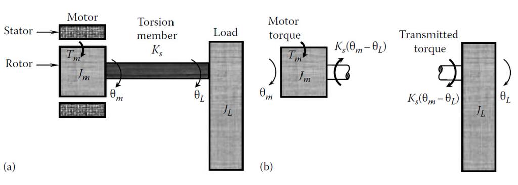
70 Torque Sensors: A torque sensor or torque transducer or torquemeter is a device for measuring and recording the torque on a rotating system, such as an engine, crankshaft, gearbox, transmission, rotor, a bicycle crank or cap torque tester. Static torque is relatively easy to measure. Dynamic torque, on the other hand, is not easy to measure, since it generally requires transfer of some effect (electric or magnetic) from the shaft being measured to a static system. Commonly, torque sensors or torque transducers use strain gauges applied to a rotating shaft or axle. With this method, a means to power the strain gauge bridge is necessary, as well as a means to receive the signal from the rotating shaft. This can be accomplished using slip rings, wireless telemetry, or rotary transformers. Newer types of torque transducers add conditioning electronics and an A/D converter to the rotating shaft. Stator electronics then read the digital signals and convert those signals to a high-level analog output signal, such as +/-10VDC. Strain-Gage Torque Sensors: Simple method of torque sensing is: To connect a torsion member between the drive unit and the (driven) load in series, as shown in diagram, and to measure the torque in the torsion member. If a circular shaft (solid or hollow) is used as the torsion member, the torque strain relationship becomes relatively simple, and is given by: Page- 70
71 From Last Page: = ; is the gage factor (or sensitivity) of the strain gages and The bridge constant k depends on the number of active strain-gages used. Strain gages are assumed to be mounted along a principal direction and three possible configurations are: Page- 71
72 Page- 72
73 Page- 73
5. Transducers Definition and General Concept of Transducer Classification of Transducers
 5.1. Definition and General Concept of Definition The transducer is a device which converts one form of energy into another form. Examples: Mechanical transducer and Electrical transducer Electrical A
Introduction to Measurement Systems
 MFE 3004 Mechatronics I Measurement Systems Dr Conrad Pace Page 4.1 Introduction to Measurement Systems Role of Measurement Systems Detection receive an external stimulus (ex. Displacement) Selection measurement
Electronic Instrumentation and Measurements
 Electronic Instrumentation and Measurements A fundamental part of many electromechanical systems is a measurement system that composed of four basic parts: Sensors Signal Conditioning Analog-to-Digital-Conversion
MECE 3320 Measurements & Instrumentation. Data Acquisition
 MECE 3320 Measurements & Instrumentation Data Acquisition Dr. Isaac Choutapalli Department of Mechanical Engineering University of Texas Pan American Sampling Concepts 1 f s t Sampling Rate f s 2 f m or
Page ENSC387 - Introduction to Electro-Mechanical Sensors and Actuators: Simon Fraser University Engineering Science
 Motor Driver and Feedback Control: The feedback control system of a dc motor typically consists of a microcontroller, which provides drive commands (rotation and direction) to the driver. The driver is
VARIABLE INDUCTANCE TRANSDUCER
 VARIABLE INDUCTANCE TRANSDUCER These are based on a change in the magnetic characteristic of an electrical circuit in response to a measurand which may be displacement, velocity, acceleration, etc. 1.
9/28/2010. Chapter , The McGraw-Hill Companies, Inc.
 Chapter 4 Sensors are are used to detect, and often to measure, the magnitude of something. They basically operate by converting mechanical, magnetic, thermal, optical, and chemical variations into electric
As before, the speed resolution is given by the change in speed corresponding to a unity change in the count. Hence, for the pulse-counting method
 Velocity Resolution with Step-Up Gearing: As before, the speed resolution is given by the change in speed corresponding to a unity change in the count. Hence, for the pulse-counting method It follows that
PVA Sensor Specifications
 Position, Velocity, and Acceleration Sensors 24.1 Sections 8.2-8.5 Position, Velocity, and Acceleration (PVA) Sensors PVA Sensor Specifications Good website to start your search for sensor specifications:
 Page 1 of 6 A Historical Perspective From Aristotle to Hawking Force & Its Effects Measurement Limitations The Strain Gage Sensor Designs Measuring Circuits Application & Installation Process Pressure
Signal Conditioning Fundamentals for PC-Based Data Acquisition Systems
 Application Note 048 Signal Conditioning Fundamentals for PC-Based Data Acquisition Systems Introduction PC-based data acquisition (DAQ) systems and plugin boards are used in a very wide range of applications
Position Sensors. The Potentiometer.
 Position Sensors In this tutorial we will look at a variety of devices which are classed as Input Devices and are therefore called "Sensors" and in particular those sensors which are Positional in nature
ACTUATORS AND SENSORS. Joint actuating system. Servomotors. Sensors
 ACTUATORS AND SENSORS Joint actuating system Servomotors Sensors JOINT ACTUATING SYSTEM Transmissions Joint motion low speeds high torques Spur gears change axis of rotation and/or translate application
Developer Techniques Sessions
 1 Developer Techniques Sessions Physical Measurements and Signal Processing Control Systems Logging and Networking 2 Abstract This session covers the technologies and configuration of a physical measurement
COVENANT UNIVERSITY NIGERIA TUTORIAL KIT OMEGA SEMESTER PROGRAMME: MECHANICAL ENGINEERING
 COVENANT UNIVERSITY NIGERIA TUTORIAL KIT OMEGA SEMESTER PROGRAMME: MECHANICAL ENGINEERING COURSE: MCE 527 DISCLAIMER The contents of this document are intended for practice and leaning purposes at the
CHAPTER 3. Instrumentation Amplifier (IA) Background. 3.1 Introduction. 3.2 Instrumentation Amplifier Architecture and Configurations
 Background. 3.1 Introduction. 3.2 Instrumentation Amplifier Architecture and Configurations") CHAPTER 3 Instrumentation Amplifier (IA) Background 3.1 Introduction The IAs are key circuits in many sensor readout systems where, there is a need to amplify small differential signals in the presence
CHAPTER 3 Instrumentation Amplifier (IA) Background 3.1 Introduction The IAs are key circuits in many sensor readout systems where, there is a need to amplify small differential signals in the presence
Ultrasonic. Advantages
 Ultrasonic Advantages Non-Contact: Nothing touches the target object Measures Distance: The distance to the target is measured, not just its presence Long and Short Range: Objects can be sensed from 2
Introduction. ELCT903, Sensor Technology Electronics and Electrical Engineering Department 1. Dr.-Eng. Hisham El-Sherif
 Introduction In automation industry every mechatronic system has some sensors to measure the status of the process variables. The analogy between the human controlled system and a computer controlled system
Shaft encoders are digital transducers that are used for measuring angular displacements and angular velocities.
 Shaft Encoders: Shaft encoders are digital transducers that are used for measuring angular displacements and angular velocities. Encoder Types: Shaft encoders can be classified into two categories depending
 VIDYARTHIPLUS - ANNA UNIVERSITY ONLINE STUDENTS COMMUNITY UNIT 1 DC MACHINES PART A 1. State Faraday s law of Electro magnetic induction and Lenz law. 2. Mention the following functions in DC Machine (i)
Electronic Systems - B1 23/04/ /04/ SisElnB DDC. Chapter 2
 Politecnico di Torino - ICT school Goup B - goals ELECTRONIC SYSTEMS B INFORMATION PROCESSING B.1 Systems, sensors, and actuators» System block diagram» Analog and digital signals» Examples of sensors»
ELECTRONIC SYSTEMS. Introduction. B1 - Sensors and actuators. Introduction
 Politecnico di Torino - ICT school Goup B - goals ELECTRONIC SYSTEMS B INFORMATION PROCESSING B.1 Systems, sensors, and actuators» System block diagram» Analog and digital signals» Examples of sensors»
CHAPTER 9 BRIDGES, STRAIN GAGES AND SOME VARIABLE IMPEDANCE TRANSDUCERS
 CHPTE 9 BIDGES, STIN GGES ND SOME IBLE IMPEDNCE TNSDUCES Many transducers translate a change in the quantity you wish to measure into a change in impedance, i.e., resistance, capacitance or inductance.
SYNCHRONOUS MACHINES
 SYNCHRONOUS MACHINES The geometry of a synchronous machine is quite similar to that of the induction machine. The stator core and windings of a three-phase synchronous machine are practically identical
Latest Control Technology in Inverters and Servo Systems
 Latest Control Technology in Inverters and Servo Systems Takao Yanase Hidetoshi Umida Takashi Aihara. Introduction Inverters and servo systems have achieved small size and high performance through the
Actuators, sensors and control architecture
 Actuators, sensors and control architecture a robot is composed of three fundamental parts actuators besides motors and transmissions, they constitute the locomotion apparatus (wheels, crawlers, mechanical
CHAPTER 2 D-Q AXES FLUX MEASUREMENT IN SYNCHRONOUS MACHINES
 22 CHAPTER 2 D-Q AXES FLUX MEASUREMENT IN SYNCHRONOUS MACHINES 2.1 INTRODUCTION For the accurate analysis of synchronous machines using the two axis frame models, the d-axis and q-axis magnetic characteristics
EE401,EC401,DEE19,DETE19
 EE401,EC401,DEE19,DETE19 IV SEMESTER DIPLOMA EXAMINATION, JANUARY 2013 LINEAR & DIGITAL ICs Time: 3 Hours Max. Marks: 75 GROUP A : Answer any three questions. (Question No. 1 is compulsory) Q.1 What is
Electronic Measurements & Instrumentation. 1. Draw the Maxwell s Bridge Circuit and derives the expression for the unknown element at balance?
 UNIT -6 1. Draw the Maxwell s Bridge Circuit and derives the expression for the unknown element at balance? Ans: Maxwell's bridge, shown in Fig. 1.1, measures an unknown inductance in of standard arm offers
3. What is hysteresis loss? Also mention a method to minimize the loss. (N-11, N-12)
") DHANALAKSHMI COLLEGE OF ENGINEERING, CHENNAI DEPARTMENT OF ELECTRICAL AND ELECTRONICS ENGINEERING EE 6401 ELECTRICAL MACHINES I UNIT I : MAGNETIC CIRCUITS AND MAGNETIC MATERIALS Part A (2 Marks) 1. List
DHANALAKSHMI COLLEGE OF ENGINEERING, CHENNAI DEPARTMENT OF ELECTRICAL AND ELECTRONICS ENGINEERING EE 6401 ELECTRICAL MACHINES I UNIT I : MAGNETIC CIRCUITS AND MAGNETIC MATERIALS Part A (2 Marks) 1. List
Sensors for Mechatronics
 Sensors for Mechatronics Paul P.L Regtien Hertgelo The Netherlands AMSTERDAM BOSTON HEIDELBERG LONDON NEW YORK' OXFORD ELSEVIER PARIS SAN DIEGO SAN FRANCISCO SINGAPORE SYDNEY TOKYO Contents Preface xi
Signal Conditioning Systems
 Note-13 1 Signal Conditioning Systems 2 Generalized Measurement System: The output signal from a sensor has generally to be processed or conditioned to make it suitable for the next stage Signal conditioning
The units of vibration depend on the vibrational parameter, as follows:
 Vibration Measurement Vibration Definition Basically, vibration is oscillating motion of a particle or body about a fixed reference point. Such motion may be simple harmonic (sinusoidal) or complex (non-sinusoidal).
Module 2. Measurement Systems. Version 2 EE IIT, Kharagpur 1
 Module Measurement Systems Version EE IIT, Kharagpur 1 Lesson 9 Signal Conditioning Circuits Version EE IIT, Kharagpur Instructional Objective The reader, after going through the lesson would be able to:
1. Explain in detail the constructional details and working of DC motor.
 DHANALAKSHMI SRINIVASAN INSTITUTE OF RESEARCH AND TECHNOLOGY, PERAMBALUR DEPT OF ECE EC6352-ELECTRICAL ENGINEERING AND INSTRUMENTATION UNIT 1 PART B 1. Explain in detail the constructional details and
R30D RVDTs DC-Operated Rotary Variable Differential Transformers
 R30D RVDTs DC-Operated Rotary Variable Differential Transformers RVDTs incorporate a proprietary noncontact design that dramatically improves long term reliability when compared to other traditional rotary
Active Vibration Isolation of an Unbalanced Machine Tool Spindle
 Active Vibration Isolation of an Unbalanced Machine Tool Spindle David. J. Hopkins, Paul Geraghty Lawrence Livermore National Laboratory 7000 East Ave, MS/L-792, Livermore, CA. 94550 Abstract Proper configurations
Downloaded from Downloaded from
 IV SEMESTER FINAL EXAMINATION- 2002 SUBJECT: BEG232EC, Instrumentation Candidates are required to give their answers in their own words as far as practicable. The figure in the margin indicates full marks.
Sensors and Actuators Introduction to sensors
 Sensors and Actuators Introduction to sensors Sander Stuijk (s.stuijk@tue.nl) Department of Electrical Engineering Electronic Systems INDUCTIVE SENSORS (Chapter 3.4, 7.3) 3 Inductive sensors 4 Inductive
ni.com Sensor Measurement Fundamentals Series
 Sensor Measurement Fundamentals Series Introduction to Data Acquisition Basics and Terminology Litkei Márton District Sales Manager National Instruments What Is Data Acquisition (DAQ)? 3 Why Measure? Engineers
Strain Gauge Measurement A Tutorial
 Application Note 078 Strain Gauge Measurement A Tutorial What is Strain? Strain is the amount of deformation of a body due to an applied force. More specifically, strain (ε) is defined as the fractional
ECET 211 Electric Machines & Controls Lecture 4-2 Motor Control Devices: Lecture 4 Motor Control Devices
 ECET 211 Electric Machines & Controls Lecture 4-2 Motor Control Devices: Part 3. Sensors, Part 4. Actuators Text Book: Electric Motors and Control Systems, by Frank D. Petruzella, published by McGraw Hill,
Sensors. Chapter 3. Storey: Electrical & Electronic Systems Pearson Education Limited 2004 OHT 3.1
 Sensors Chapter 3 Introduction Describing Sensor Performance Temperature Sensors Light Sensors Force Sensors Displacement Sensors Motion Sensors Sound Sensors Sensor Interfacing Storey: Electrical & Electronic
APPLICATION NOTE 695 New ICs Revolutionize The Sensor Interface
 Maxim > Design Support > Technical Documents > Application Notes > Sensors > APP 695 Keywords: high performance, low cost, signal conditioner, signal conditioning, precision sensor, signal conditioner,
Making Basic Strain Measurements
 IOtech Product Marketing Specialist steve.radecky@iotech.com Making Basic Strain Measurements using 24-Bit IOtech Hardware INTRODUCTION Strain gages are sensing devices used in a variety of physical test
An Instrumentation System
 Transducer As Input Elements to Instrumentation System An Instrumentation System Input signal (measurand) electrical or non-electrical Input Device Signal Conditioning Circuit Output Device? -amplifier
PART 2 - ACTUATORS. 6.0 Stepper Motors. 6.1 Principle of Operation
 6.1 Principle of Operation PART 2 - ACTUATORS 6.0 The actuator is the device that mechanically drives a dynamic system - Stepper motors are a popular type of actuators - Unlike continuous-drive actuators,
WIRELESS MEASUREMENT SYSTEMS
 WIRELESS MEASUREMENT SYSTEMS REAL-TIME WIRELESS DATA TRANSFER ROD STRAIN PRESSURE OIL FLOW FRICTION TEMPERATURE PISTON TEMPERATURE RING PRESSURE RING MOTION PIN MOTION STRAIN FRICTION We custom build real-time
STRAIN, FORCE, PRESSURE, AND FLOW MEASUREMENTS
 SECTION 4 STRAIN,, PRESSURE, AND FLOW MEASUREMENTS Walt Kester STRAIN GAGES The most popular electrical elements used in force measurements include the resistance strain gage, the semiconductor strain
Synchronous Machines Study Material
 Synchronous machines: The machines generating alternating emf from the mechanical input are called alternators or synchronous generators. They are also known as AC generators. All modern power stations
Anthony Chu. Basic Accelerometer types There are two classes of accelerometer in general: AC-response DC-response
 Engineer s Circle Choosing the Right Type of Accelerometers Anthony Chu As with most engineering activities, choosing the right tool may have serious implications on the measurement results. The information
Industrial Sensors. Proximity Mechanical Optical Inductive/Capacitive. Position/Velocity Potentiometer LVDT Encoders Tachogenerator
 Proximity Mechanical Optical Inductive/Capacitive Position/Velocity Potentiometer LVDT Encoders Tachogenerator Force/Pressure Vibration/acceleration Industrial Sensors 1 Definitions Accuracy: The agreement
INTEGRATED CIRCUITS. AN109 Microprocessor-compatible DACs Dec
 INTEGRATED CIRCUITS 1988 Dec DAC products are designed to convert a digital code to an analog signal. Since a common source of digital signals is the data bus of a microprocessor, DAC circuits that are
Interface Electronic Circuits
 Lecture (5) Interface Electronic Circuits Part: 1 Prof. Kasim M. Al-Aubidy Philadelphia University-Jordan AMSS-MSc Prof. Kasim Al-Aubidy 1 Interface Circuits: An interface circuit is a signal conditioning
Section 6 - Electronics
 Section 6 - Electronics 6.1. Power for Excitation Piezoresistive transducers are passive devices and require an external power supply to provide the necessary current (I x ) or voltage excitation (E x
INSTITUTE OF AERONAUTICAL ENGINEERING (AUTONOMOUS) Dundigal, Hyderabad
 Dundigal, Hyderabad") INSTITUTE OF AERONAUTICAL ENGINEERING (AUTONOMOUS) Dundigal, Hyderabad - 500 043 CIVIL ENGINEERING ASSIGNMENT Name : Electrical and Electronics Engineering Code : A30203 Class : II B. Tech I Semester Branch
INSTITUTE OF AERONAUTICAL ENGINEERING (AUTONOMOUS) Dundigal, Hyderabad - 500 043 CIVIL ENGINEERING ASSIGNMENT Name : Electrical and Electronics Engineering Code : A30203 Class : II B. Tech I Semester Branch
Velocity and Acceleration Measurements
 Lecture (8) Velocity and Acceleration Measurements Prof. Kasim M. Al-Aubidy Philadelphia University-Jordan AMSS-MSc Prof. Kasim Al-Aubidy 1 Introduction: The measure of velocity depends on the scale of
UNIT II MEASUREMENT OF POWER & ENERGY
 UNIT II MEASUREMENT OF POWER & ENERGY Dynamometer type wattmeter works on a very simple principle which is stated as "when any current carrying conductor is placed inside a magnetic field, it experiences
Elements of Haptic Interfaces
 Elements of Haptic Interfaces Katherine J. Kuchenbecker Department of Mechanical Engineering and Applied Mechanics University of Pennsylvania kuchenbe@seas.upenn.edu Course Notes for MEAM 625, University
Signal Characteristics and Conditioning
 Signal Characteristics and Conditioning Starting from the sensors, and working up into the system:. What characterizes the sensor signal types. Accuracy and Precision with respect to these signals 3. General
Electronics Interview Questions
 Electronics Interview Questions 1. What is Electronic? The study and use of electrical devices that operate by controlling the flow of electrons or other electrically charged particles. 2. What is communication?
CHOOSING THE RIGHT TYPE OF ACCELEROMETER
 As with most engineering activities, choosing the right tool may have serious implications on the measurement results. The information below may help the readers make the proper accelerometer selection.
A Subsidiary of Regal-Beloit Corporation. AC Inverter Terminology
 AP200-9/01 Acceleration The rate of change in velocity as a function of time. Acceleration usually refers to increasing velocity and deceleration to decreasing velocity. Acceleration Boost During acceleration,
CAH CARD. user leaflet. 1 of 15. Copyright Issue 12.1 January 2015
 CAH CARD user leaflet 1 of 15 INTRODUCTION The function of the card is to energise a transducer (LVDT, Half-Bridge or Full-Bridge) with a stable a.c. waveform and to convert the output of the transducer
EE T55 MEASUREMENTS AND INSTRUMENTATION
 EE T55 MEASUREMENTS AND INSTRUMENTATION UNIT V: TRANSDUCERS Temperature transducers-rtd, thermistor, Thermocouple-Displacement transducer-inductive, capacitive, LVDT, Pressure transducer Bourdon tube,
Module 1. Introduction. Version 2 EE IIT, Kharagpur
 Module 1 Introduction Lesson 1 Introducing the Course on Basic Electrical Contents 1 Introducing the course (Lesson-1) 4 Introduction... 4 Module-1 Introduction... 4 Module-2 D.C. circuits.. 4 Module-3
3 Circuit Theory. 3.2 Balanced Gain Stage (BGS) Input to the amplifier is balanced. The shield is isolated
 Input to the amplifier is balanced. The shield is isolated") Rev. D CE Series Power Amplifier Service Manual 3 Circuit Theory 3.0 Overview This section of the manual explains the general operation of the CE power amplifier. Topics covered include Front End Operation,
Rev. D CE Series Power Amplifier Service Manual 3 Circuit Theory 3.0 Overview This section of the manual explains the general operation of the CE power amplifier. Topics covered include Front End Operation,
Integrated Circuit: Classification:
 Integrated Circuit: It is a miniature, low cost electronic circuit consisting of active and passive components that are irreparably joined together on a single crystal chip of silicon. Classification:
Figure 1.1 Mechatronic system components (p. 3)
") Figure 1.1 Mechatronic system components (p. 3) Example 1.2 Measurement System Digital Thermometer (p. 5) Figure 2.2 Electric circuit terminology (p. 13) Table 2.2 Resistor color band codes (p. 18) Figure
Figure 1.1 Mechatronic system components (p. 3) Example 1.2 Measurement System Digital Thermometer (p. 5) Figure 2.2 Electric circuit terminology (p. 13) Table 2.2 Resistor color band codes (p. 18) Figure
Table of Contents...2. About the Tutorial...6. Audience...6. Prerequisites...6. Copyright & Disclaimer EMI INTRODUCTION Voltmeter...
 1 Table of Contents Table of Contents...2 About the Tutorial...6 Audience...6 Prerequisites...6 Copyright & Disclaimer...6 1. EMI INTRODUCTION... 7 Voltmeter...7 Ammeter...8 Ohmmeter...8 Multimeter...9
Part 10: Transducers
 Part 10: Transducers 10.1: Classification of Transducers An instrument may be defined as a device or a system which is designed to maintain a functional relationship between prescribed properties of physical
Chapter 2 Analog-to-Digital Conversion...
 Chapter... 5 This chapter examines general considerations for analog-to-digital converter (ADC) measurements. Discussed are the four basic ADC types, providing a general description of each while comparing
GAS (Geometric Anti Spring) filter and LVDT (Linear Variable Differential Transformer) Enzo Tapia Lecture 2. KAGRA Lecture 2 for students
 filter and LVDT (Linear Variable Differential Transformer) Enzo Tapia Lecture 2. KAGRA Lecture 2 for students") GAS (Geometric Anti Spring) filter and LVDT (Linear Variable Differential Transformer) Enzo Tapia Lecture 2 1 Vibration Isolation Systems GW event induces a relative length change of about 10^-21 ~ 10^-22
GAS (Geometric Anti Spring) filter and LVDT (Linear Variable Differential Transformer) Enzo Tapia Lecture 2 1 Vibration Isolation Systems GW event induces a relative length change of about 10^-21 ~ 10^-22
Electrical Materials may be referred to a metal, dielectrics,electrical insulators or conductors,paramagnetic materials and many other.
 Electrical Engineering Paper-1 Syllabus : This part is for both objective and conventional types papers : 1) EM Theory- The electromagnetic force is said to be one of the fundamental interactions in nature
the pilot valve effect of
 Actiive Feedback Control and Shunt Damping Example 3.2: A servomechanism incorporating a hydraulic relay with displacement feedback throughh a dashpot and spring assembly is shown below. [Control System
09-2 EE 4770 Lecture Transparency. Formatted 12:49, 19 February 1998 from lsli
 09-1 09-1 Displacement and Proximity Displacement transducers measure the location of an object. Proximity transducers determine when an object is near. Criteria Used in Selection of Transducer How much
Operational Amplifiers
 Operational Amplifiers Table of contents 1. Design 1.1. The Differential Amplifier 1.2. Level Shifter 1.3. Power Amplifier 2. Characteristics 3. The Opamp without NFB 4. Linear Amplifiers 4.1. The Non-Inverting
A Practical Guide to Free Energy Devices
 A Practical Guide to Free Energy Devices Part PatD14: Last updated: 25th February 2006 Author: Patrick J. Kelly This patent application shows the details of a device which it is claimed, can produce sufficient
Practical Testing Techniques For Modern Control Loops
 VENABLE TECHNICAL PAPER # 16 Practical Testing Techniques For Modern Control Loops Abstract: New power supply designs are becoming harder to measure for gain margin and phase margin. This measurement is
CHEMICAL ENGINEERING 2I03
 Student Name: Student ID: CHEMICAL ENGINEERING 2I03 DAY CLASS Duration 2 hours McMaster University Practice Exam Dr. M. Thompson The final test includes 60 questions on 12 pages. This test paper must be
System Protection and Control Subcommittee
 Power Plant and Transmission System Protection Coordination Reverse Power (32), Negative Sequence Current (46), Inadvertent Energizing (50/27), Stator Ground Fault (59GN/27TH), Generator Differential (87G),
Electrical Engineering / Electromagnetics
 Electrical Engineering / Electromagnetics. Plot voltage versus time and current versus time for the circuit with the following substitutions: A. esistor B. Capacitor C. Inductor t = 0 A/B/C A. I t t B.
Chapter 8. Digital and Analog Interfacing Methods
 Chapter 8 Digital and Analog Interfacing Methods Lesson 16 MCU Based Instrumentation Outline Resistance and Capacitance based Sensor Interface Inductance based Sensor (LVDT) Interface Current based (Light
Job Sheet 2 Servo Control
 Job Sheet 2 Servo Control Electrical actuators are replacing hydraulic actuators in many industrial applications. Electric servomotors and linear actuators can perform many of the same physical displacement
Op Amp Booster Designs
 Op Amp Booster Designs Although modern integrated circuit operational amplifiers ease linear circuit design, IC processing limits amplifier output power. Many applications, however, require substantially
Chapter 5. Operational Amplifiers and Source Followers. 5.1 Operational Amplifier
 Chapter 5 Operational Amplifiers and Source Followers 5.1 Operational Amplifier In single ended operation the output is measured with respect to a fixed potential, usually ground, whereas in double-ended
Actuators. EECS461, Lecture 5, updated September 16,
 Actuators The other side of the coin from sensors... Enable a microprocessor to modify the analog world. Examples: - speakers that transform an electrical signal into acoustic energy (sound) - remote control
Principles of operation 5
 Principles of operation 5 The following section explains the fundamental principles upon which Solartron Metrology s linear measurement products are based. > Inductive technology (gauging and displacement)
Load Cells, LVDTs and Thermocouples
 Load Cells, LVDTs and Thermocouples Introduction Load cells are utilized in nearly every electronic weighing system while LVDTs are used to measure the displacement of a moving object. Thermocouples have
DSC Lab 2: Force and Displacement Measurement Page 1
 DSC Lab 2: Force and Displacement Measurement Page 1 Overview of Laboratory on Force and Displacement Measurement This lab course introduces concepts in force and motion measurement using strain-gauge
PART A. 1. List the types of DC Motors. Give any difference between them. BTL 1 Remembering
 UNIT I DC MACHINES Three phase circuits, a review. Construction of DC machines Theory of operation of DC generators Characteristics of DC generators Operating principle of DC motors Types of DC motors
UNIVERSITY OF JORDAN Mechatronics Engineering Department Measurements & Control Lab Experiment no.1 DC Servo Motor
 UNIVERSITY OF JORDAN Mechatronics Engineering Department Measurements & Control Lab. 0908448 Experiment no.1 DC Servo Motor OBJECTIVES: The aim of this experiment is to provide students with a sound introduction
(i) Determine the admittance parameters of the network of Fig 1 (f) and draw its - equivalent circuit.
 Determine the admittance parameters of the network of Fig 1 (f) and draw its - equivalent circuit.") I.E.S-(Conv.)-1995 ELECTRONICS AND TELECOMMUNICATION ENGINEERING PAPER - I Some useful data: Electron charge: 1.6 10 19 Coulomb Free space permeability: 4 10 7 H/m Free space permittivity: 8.85 pf/m Velocity
I.E.S-(Conv.)-1995 ELECTRONICS AND TELECOMMUNICATION ENGINEERING PAPER - I Some useful data: Electron charge: 1.6 10 19 Coulomb Free space permeability: 4 10 7 H/m Free space permittivity: 8.85 pf/m Velocity
Continuous Sensors Accuracy Resolution Repeatability Linearity Precision Range
 Continuous Sensors A sensor element measures a process variable: flow rate, temperature, pressure, level, ph, density, composition, etc. Much of the time, the measurement is inferred from a second variable:
Sensors DR. GYURCSEK ISTVÁN
 DR. GYURCSEK ISTVÁN Sensors Sources and additional materials (recommended) Lambert Miklós: Szenzorok elmélet (ISBN 978-963-874001-1-3) Bp. 2009 Jacob Fraden: Handbook of Modern Sensors (ISBN 978-1-4419-6465-6)
Advanced Measurements
 Albaha University Faculty of Engineering Mechanical Engineering Department Lecture 3: Position, Displacement, and Level Ossama Abouelatta o_abouelatta@yahoo.com Mechanical Engineering Department Faculty
EKT 314 ELECTRONIC INSTRUMENTATION
 EKT 314 ELECTRONIC INSTRUMENTATION Elektronik Instrumentasi Semester 2 2012/2013 Chapter 3 Analog Signal Conditioning Session 2 Mr. Fazrul Faiz Zakaria school of computer and communication engineering.
Sensors & transducers
 Sensors & transducers Prof. H. Arya DEPT. OF AEROSPACE ENGINEERING IIT BOMBAY Sensors Sensors - A device that produces an output signal for the purpose of sensing a physical phenomenon. Sensors are also
Technical Information
 Technical Information Introduction to force sensors Driving long cable lengths Conversions, article reprints, glossary INTRODUCTION TO QUARTZ FORCE SENSORS Quartz Force Sensors are well suited for dynamic
Where: (J LM ) is the load inertia referred to the motor shaft. 8.0 CONSIDERATIONS FOR THE CONTROL OF DC MICROMOTORS. 8.
 is the load inertia referred to the motor shaft. 8.0 CONSIDERATIONS FOR THE CONTROL OF DC MICROMOTORS. 8.") Where: (J LM ) is the load inertia referred to the motor shaft. 8.0 CONSIDERATIONS FOR THE CONTROL OF DC MICROMOTORS 8.1 General Comments Due to its inherent qualities the Escap micromotor is very suitable
Where: (J LM ) is the load inertia referred to the motor shaft. 8.0 CONSIDERATIONS FOR THE CONTROL OF DC MICROMOTORS 8.1 General Comments Due to its inherent qualities the Escap micromotor is very suitable