CONSTRUCTION GUIDE Light Robot. Robobox. Level VI
|
|
|
- Malcolm Parks
- 5 years ago
- Views:
Transcription

1 CONSTRUCTION GUIDE Light Robot Robobox Level VI


2 The Light In this box dedicated to light we will discover, through 3 projects, how light can be used in our robots. First we will see how to insert headlights on our autonomous car, then we will mount a light robot capable of following the sun. Finally, we will insert a line follower to the front of our car. 3X 33Ω resistor 3X line Follower 2X LEDs 3X Photoresistor x Robot Body 3X Male-Male Cables Parts 2X Male-Female X Robot Head Cables X Female block X Footer X headlight Block X Line follower block X Stabilizer Instructions We suggest that you follow these instructions step by step. Additional details are available on your member space on Robobox.io. Please don t hesitate to ask any question, we will answer them promptly. Good luck!
 varies depending on the brightness of the part.")
3 Car Lights NTRDUCTN On modern cars, it is possible to ask the on-board computer to automatically adjust the headlights according to the surrounding brightness. We will try to do the same for our robot! For this, we will use a photoresistor included in the box. A photoresistor is a resistor whose value (in Ohm) varies depending on the brightness of the part. Specifically, the resistance decreases as the brightness increases. In our case, we want to increase the intensity of the headlights when the brightness drops, so we will use our Arduino card to reverse this relationship between resistance and current. Diagram: Photoresistor In a first step we define our variables. We will need to define the Pin that will receive the value of the photoresistor (between and 23), we will then store this data in the variable valuephoto.
4 Car Lights CODE In a second step, we will turn on the LED linked to the pinled pin with an intensity defined by the luminositeled variable. After starting communication with the serial port, we will recover the brightness using the analog ports to the left of the card. Then we will convert this value from to 23 in an intensity between and 255. The lower the luminosity of the room and the stronger our lighting. During our tests, we noticed that the luminosity of the room was around 5 on the scale from to 23, so we adapted our function to this value. To convert a value from one scale to another, we use the map() function Finally, we send the desired intensity signal to the LED with the analogwrite() function. The latter sends a signal between and 5V to the pins of the card with a tilde: '~'. These pins use the Pulse-Width Modulation (PWM) to transform a digital signal (/) into an analog signal (/255) by alternating V and 5V signals. int pinphoto = ; int valuephoto; int pinled = ; int luminositeled; void setup() { Serial.begin(96); void loop() { valeurphoto = analogread(pinphoto); Serial.print("Analog reading = "); Serial.print(valuePhoto); luminositeled = max( map(valuephoto,, 5, 255, ), ); Serial.print(" Analog write = "); Serial.println(luminositeLed); analogwrite(pinled, luminositeled); delay();

 (2) () (3) We will then connect the wire (2) to the current source and the wire (3) to ground. We will then use the circuit from month 4 and we will add the photoresistor.")
5 Car Lights _2_ BUILD Now that we understand how a photoresistor works, we will be able to install the automatic headlights on our robot car. Insert the 2 LEDs of the box inside the headlight block then: Slide female-female wire between the short leg of the left LED and the long leg of the right LED. () Plug a male-female wire into the long leg of the left LED (2) Plug a male-female wire into the short leg of the right LED. (3) (2) () (3) We will then connect the wire (2) to the current source and the wire (3) to ground. We will then use the circuit from month 4 and we will add the photoresistor. As illustrated below, when the brightness varies, the resistance in the circuit changes and therefore the voltage measured in A differs. 5V A GND

6 Car Lights _3_ CODE Finally, we have to slide the headlight block to the front of the vehicle. To do this, we must first add a female triangle block to the front of the car. Then you only have to add the headlight block as illustrated opposite: To allow your car to automatically turn on its headlights thanks to the luminosity of the room, simply add these few lines of code at the beginning of the program: int pinphoto = A; int valeurphoto; int pinled = 3; int luminositeled; Then set the function LigthsOn() which will turn on or off the headlights of our vehicle when it is in a dark room: void LightsOn() { valeurphoto = analogread(pinphoto); luminositeled = max( map(valeurphoto,, 3, 255, ), ); analogwrite(pinled, luminositeled); delay(); Finally, simply add the function LightsOn() in the loop like this: You can retrieve all the code on teamrobobox, see the videos of the car in motion and ask all the questions to help you in the construction of this robot! There you go! Your car is now able to turn on its headlights when it is in a dark room! void loop() { curdist = distanceread(); LigthsOn(); if (curdist > 2){ forward(); if (curdist < 2){ backward(); turnright(); delay(3);


7 Line Follower INTRODUCTION Let's see a new component: the line follower. The line follower is a module consisting of an infrared emitting LED and an infrared receiver. The infrared LED continuously illuminates the surface in front of which it is oriented and the receiver indicates whether or not it perceives the reflection of a light. As you surely know, white reflects all the light it receives while black absorbs it. So when your infrared LED illuminates a white surface, the receiver will detect a signal and when the surface is dark, the receiver will not detect anything. Transmitter Receiver Transmitter Receiver Our challenge here is to set up a line detector on our car to make it follow a black line on the ground. For this challenge we will need a block and three line follower modules. First, push the modules into the appropriate block and place it in the front of the vehicle (just like the headlights). Then connect the GND and 5V cables of the modules to the breadboard (in series with the other GND and 5V). Finally, connect the receiver cables (green) to the analog pins, and 2. A A GND 3.3V A2
8 Line Follower _2_ BUILD Before the setup() function: int pinlined = A; int pinlinec = A; int pinlineg = A2; int instr[2]; In the setup() function: pinmode(pinlined,input); pinmode(pinlinec,input); pinmode(pinlineg,input); Now we are interested in programming our vehicle. The purpose of the code will be to follow a black line using the three sensors. So : - The sensor of the center reads a black line whereas those on the sides don t, the car must go straight ahead. - Only one of the lateral sensors identifies a black line, the car should turn in that direction. - None of the sensors see a line, the car is out of track and must therefore retreat. After the loop() function: void forward(int mot, int mot2 ){ dirmoteur(,,mot); dirmoteur(2,,mot2); In the loop(): void loop() { int check = checkline(); if (check == ){ forward(instr[],instr[]); Before the setup() function we will add three global variables, pinlineg, pinlined and pinlinec, initialized to A, A and A2, which will correspond to the input pin of the sensor signal. We also create an array instr[2] in which we will write the instructions for the engines. Then we will specify in the setup() function that these pins will be used as input. Then, we create the advance function(int word, int word2) which has two arguments word and word2. These two integers tell you how fast the right and left wheels go. Inside the loop(), we run a checkline() function whose purpose is to update the instructions for the motors and return '' if the sensor has read the data. Finally, we ask the car to proceed at the speed set in the checkline() function.
9 Line Follower Now we will create the checkline() function. This function will probe the values of the line sensors and turn it into an instruction for the car. Connected to the 3.3V, sensors return a value of about 645 if no line is seen, and a lower value (between 2 and 5) if a line is present. First, we will transform any value less than 62 into zero and any higher value into. _3_ CODE int checkline(){ int lineg = (analogread(pinlineg)>62)?():(); int linec = (analogread(pinlinec)>62)?():(); int lined = (analogread(pinlined)>62)?():(); int Recept[4] = {lineg,linec,lined,; int mat[2][4] = {{2,8,6,,{6,8,2,; int motor[2] = {,; for(int i = ; i<2; i++){ for( int j = ; j<4; j++){ motor[i] = motor[i] + ( mat[i][j] * Recept[j]) ; instr[] = motor[]; instr[] = motor[]; if (( motor[] + motor[]) == ){return ; return ; We end up with a vector of 3 booleans (for example: [,,]) corresponding to the 3 sensors. We will also add a fourth integer :. We will then multiply this vector by a matrix to deduce the speeds to apply to our engines: Line detected in the center: Line detected left: Line detected in center + left: = ( ) = (8, 8) Line detected to the right: Line detected in the center + right: = (2, 6) = (6, 2) The instructions for our car are now set! = (, 4) = (4, )

.")
.")


10 Light Robot BUILD Now, let us attack the Robot Light, the robot capable of orienting itself towards light whatever its origin. 2 Start by inserting the "Servo" into the "Footer" (). Take a helix in the shape of a cross and insert it on the other "Servo" (2). "S", "Short", indicates the short side, and "L" the side "Long". Snap it into the "Body Back". Insert the "T" of the foot into the slot provided for this purpose, and close the assembly by clipping the "Body Body Front" into the "Body Back". Finally, add the head to your robot. You can then hang the robot, the breadboard on its base and the UNO card on the cardholder. 3 You will now have to insert the photoresistors into the holes provided for this purpose and bring out their legs on the top of the robot head. Using the stabilizer, you can now connect the Uno card, the breadboard and the light robot to the same surface. You will need to use the cardholder and the boardholder to fit those two elements.

11 Light Robot BUILD Now let's take a look at the circuit of our model. On the left we find the 3 photoresistors connected to the head of our robot. These photoresistors have two pins, we plug 5V into one and one output into the other. Just as in the first model we set up a voltage divider to know the strength of the resistance and therefore the intensity of the brightness. 5V GND The stronger the brightness, the more the photoresistor will let the current flow. The voltage drop between point a and b will then be lower than between point b and c. A returning the voltage between point b and ground, A will be larger. Brightness Resistor Resistor 2 Total resistance (R+R2) A-B Voltage 5V *(R/(R+R2)) a b c A B-C Voltage 5V - T(a-b) Cas Forte 33 43,2 3,8 Cas 2 Faible ,8,2 In the diagram, the three green wires represent this intermediate voltage. We connect them to the pins A, A and A2 to know their value (between and 23. The servo is connected to pin # 5.
12 Light Robot The objective of our robot light detector is to turn to the strongest light source nearby. For this, it has 3 photoresistors capable of analyzing the intensity of the light in the surroundings. We will therefore recover the intensity of the light (value between and 23) and deduce the angle to which the engine must place, thanks to some rules of trigonometry. In a first step, the sensors detect the brightness (). This system can be compared to a system of forces, or to a set of vectors (2). Thanks to this set of vectors, we can deduce the origin of the light source: Let us find the coordinates (x, y) of the resulting vector = Y = 2 cos 6 cos 6 2 X = sin 6 + sin 6 2 Length = X 2 + Y 2 To determine the angle, we could use the arccosine: Angle = cos (Length/Y) But this one would not give us the sign (+ or -) of the angle. We prefer the arc-tangeant: Angle = tan (x, y) We now have the angle in which our robot must go, but we need to take into account our robot s constraints: Our robot can move only from to 8 and its neutral position is at 9 and not at. We will therefore limit its movements and use the map() function to solve these constraints. _2_ TH3RY Detection of intensity 2- Analogy system of forces 3- Determination of the origin of light θ Adaptation to robot constraints 9 8
13 Light Robot #include <Servo.h> Servo servotronc; void setup() { servotronc.attach(5); pinmode(a,input); pinmode(a,input); pinmode(a2,input); Serial.begin(96); void loop() { int position = 9; servotronc.write(9); delay(2); int a = analogread(a); int b = analogread(a); int c = analogread(a2); _3_ CODE Let's now go to the programming of our robot. First we insert our servo library, the one we use since the beginning of our assemblies. We create a Servo object: 'servotronc' and then initialize the program with the setup() function where we say that a motor is attached to pin 5 and that the pins A to A2 will be information entries. We then run the loop() function. Inside it, we will indicate the starting position of the servo (9 ) and then read the data of the photoresistors: A b A a c A2 int y = b - cos(6*pi/8)*a - cos(6*pi/8)*c; int x = - sin(6*pi/8)*a + sin(6*pi/8)*c; float angle = atan2(x,y)* (8 / PI); int constrangle = ; if(angle< -9){constrAngle = -9; else if(angle> 9){constrAngle = 9; else {constrangle = angle;; constrangle = map(constrangle, -9,9,8,); Serial.print(a); Serial.print(" "); Serial.print(b); Serial.print(" "); Serial.print(c); Serial.print(" "); Serial.print(x); Serial.print(" "); Serial.print(y); Serial.print(" "); Serial.print(angle); Serial.print(" "); Serial.print(constrAngle); Serial.println(" "); servotronc.write(constrangle); delay(); From these values, we will calculate the origin of the strongest light, as explained on the previous page. The only difference is that we add (PI / 8), this ratio is added to transform the radians into degrees. Then we adapt our results to the constraints of the robot thanks to the map() function, as explained previously (4). To make sure we have good measurements, we print out our different results before asking our robot to move at the calculated angle.
14
15
16
CONSTRUCTION GUIDE Capacitor, Transistor & Motorbike. Robobox. Level VII
 CONSTRUCTION GUIDE Capacitor, Transistor & Motorbike Robobox Level VII Capacitor, Transistor & Motorbike In this box, we will understand in more detail the operation of DC motors, transistors and capacitor.
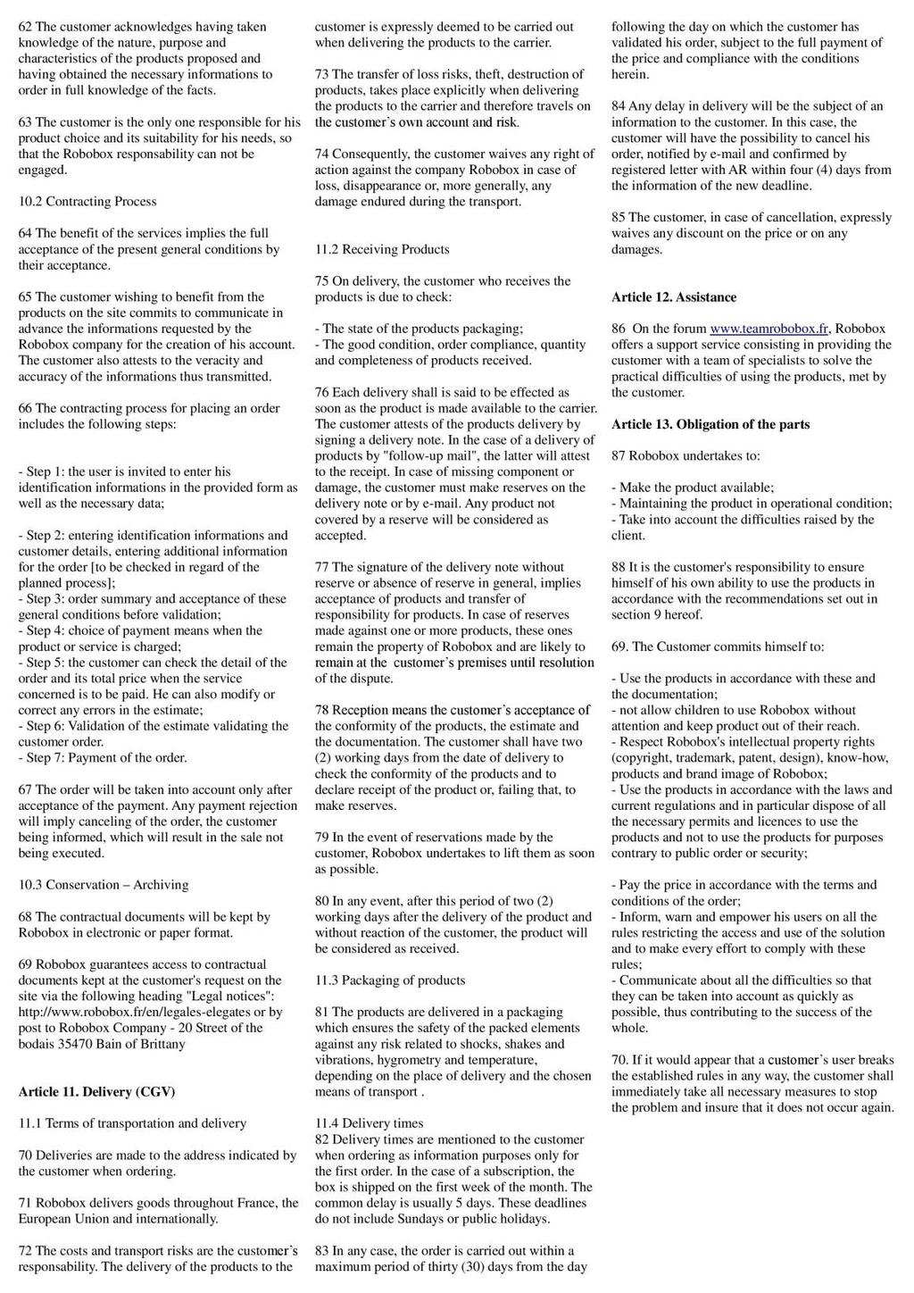
100UF CAPACITOR POTENTIOMETER SERVO MOTOR MOTOR ARM. MALE HEADER PIN (3 pins) INGREDIENTS
 INGREDIENTS") 05 POTENTIOMETER SERVO MOTOR MOTOR ARM 100UF CAPACITOR MALE HEADER PIN (3 pins) INGREDIENTS 63 MOOD CUE USE A SERVO MOTOR TO MAKE A MECHANICAL GAUGE TO POINT OUT WHAT SORT OF MOOD YOU RE IN THAT DAY Discover:
05 POTENTIOMETER SERVO MOTOR MOTOR ARM 100UF CAPACITOR MALE HEADER PIN (3 pins) INGREDIENTS 63 MOOD CUE USE A SERVO MOTOR TO MAKE A MECHANICAL GAUGE TO POINT OUT WHAT SORT OF MOOD YOU RE IN THAT DAY Discover:
CONSTRUCTION GUIDE Robotic Arm. Robobox. Level II
 CONSTRUCTION GUIDE Robotic Arm Robobox Level II Robotic Arm This month s robot is a robotic arm with two degrees of freedom that will teach you how to use motors. You will then be able to move the arm
1. Introduction to Analog I/O
 EduCake Analog I/O Intro 1. Introduction to Analog I/O In previous chapter, we introduced the 86Duino EduCake, talked about EduCake s I/O features and specification, the development IDE and multiple examples
Lab 06: Ohm s Law and Servo Motor Control
 CS281: Computer Systems Lab 06: Ohm s Law and Servo Motor Control The main purpose of this lab is to build a servo motor control circuit. As with prior labs, there will be some exploratory sections designed
Arduino and Servo Motor
 Arduino and Servo Motor 1. Basics of the Arduino Board and Arduino a. Arduino is a mini computer that can input and output data using the digital and analog pins b. Arduino Shield: mounts on top of Arduino
A servo is an electric motor that takes in a pulse width modulated signal that controls direction and speed. A servo has three leads:
 Project 4: Arduino Servos Part 1 Description: A servo is an electric motor that takes in a pulse width modulated signal that controls direction and speed. A servo has three leads: a. Red: Current b. Black:
Arduino: Sensors for Fun and Non Profit
 Arduino: Sensors for Fun and Non Profit Slides and Programs: http://pamplin.com/dms/ Nicholas Webb DMS: @NickWebb 1 Arduino: Sensors for Fun and Non Profit Slides and Programs: http://pamplin.com/dms/
CONSTRUCTION GUIDE IR Alarm. Robobox. Level I
 CONSTRUCTION GUIDE Robobox Level I This month s montage is an that will allow you to detect any intruder. When a movement is detected, the alarm will turn its LEDs on and buzz to a personalized tune. 1X
Objectives: Learn what an Arduino is and what it can do Learn what an LED is and how to use it Be able to wire and program an LED to blink
 Objectives: Learn what an Arduino is and what it can do Learn what an LED is and how to use it Be able to wire and program an LED to blink By the end of this session: You will know how to use an Arduino
Pulse Width Modulation and
 Pulse Width Modulation and analogwrite ( ); 28 Materials needed to wire one LED. Odyssey Board 1 dowel Socket block Wire clip (optional) 1 Female to Female (F/F) wire 1 F/F resistor wire LED Note: The
Project #6 Introductory Circuit Analysis
 Project #6 Introductory Circuit Analysis Names: Date: Class Session (Please check one) 11AM 1PM Group & Kit Number: Instructions: Please complete the following questions to successfully complete this project.
Lesson 13. The Big Idea: Lesson 13: Infrared Transmitters
 Lesson Lesson : Infrared Transmitters The Big Idea: In Lesson 12 the ability to detect infrared radiation modulated at 38,000 Hertz was added to the Arduino. This lesson brings the ability to generate
Computational Crafting with Arduino. Christopher Michaud Marist School ECEP Programs, Georgia Tech
 Computational Crafting with Arduino Christopher Michaud Marist School ECEP Programs, Georgia Tech Introduction What do you want to learn and do today? Goals with Arduino / Computational Crafting Purpose
1. Controlling the DC Motors
 E11: Autonomous Vehicles Lab 5: Motors and Sensors By this point, you should have an assembled robot and Mudduino to power it. Let s get things moving! In this lab, you will write code to test your motors
LED + Servo 2 devices, 1 Arduino
 LED + Servo 2 devices, 1 Arduino Learn to connect and write code to control both a Servo and an LED at the same time. Many students who come through the lab ask if they can use both an LED and a Servo
CURIE Academy, Summer 2014 Lab 2: Computer Engineering Software Perspective Sign-Off Sheet
 Lab : Computer Engineering Software Perspective Sign-Off Sheet NAME: NAME: DATE: Sign-Off Milestone TA Initials Part 1.A Part 1.B Part.A Part.B Part.C Part 3.A Part 3.B Part 3.C Test Simple Addition Program
Two Hour Robot. Lets build a Robot.
 Lets build a Robot. Our robot will use an ultrasonic sensor and servos to navigate it s way around a maze. We will be making 2 voltage circuits : A 5 Volt for our ultrasonic sensor, sound and lights powered
Coding with Arduino to operate the prosthetic arm
 Setup Board Install FTDI Drivers This is so that your RedBoard will be able to communicate with your computer. If you have Windows 8 or above you might already have the drivers. 1. Download the FTDI driver
Attribution Thank you to Arduino and SparkFun for open source access to reference materials.
 Attribution Thank you to Arduino and SparkFun for open source access to reference materials. Contents Parts Reference... 1 Installing Arduino... 7 Unit 1: LEDs, Resistors, & Buttons... 7 1.1 Blink (Hello
Arduino Control of Tetrix Prizm Robotics. Motors and Servos Introduction to Robotics and Engineering Marist School
 Arduino Control of Tetrix Prizm Robotics Motors and Servos Introduction to Robotics and Engineering Marist School Motor or Servo? Motor Faster revolution but less Power Tetrix 12 Volt DC motors have a
You'll create a lamp that turns a light on and off when you touch a piece of conductive material
 TOUCHY-FEELY LAMP You'll create a lamp that turns a light on and off when you touch a piece of conductive material Discover : installing third party libraries, creating a touch sensor Time : 5 minutes
INA169 Breakout Board Hookup Guide
 Page 1 of 10 INA169 Breakout Board Hookup Guide CONTRIBUTORS: SHAWNHYMEL Introduction Have a project where you want to measure the current draw? Need to carefully monitor low current through an LED? The
Sten BOT Robot Kit 1 Stensat Group LLC, Copyright 2016
 StenBOT Robot Kit Stensat Group LLC, Copyright 2016 1 Legal Stuff Stensat Group LLC assumes no responsibility and/or liability for the use of the kit and documentation. There is a 90 day warranty for the
Sten-Bot Robot Kit Stensat Group LLC, Copyright 2013
 Sten-Bot Robot Kit Stensat Group LLC, Copyright 2013 Legal Stuff Stensat Group LLC assumes no responsibility and/or liability for the use of the kit and documentation. There is a 90 day warranty for the
FABO ACADEMY X ELECTRONIC DESIGN
 ELECTRONIC DESIGN MAKE A DEVICE WITH INPUT & OUTPUT The Shanghaino can be programmed to use many input and output devices (a motor, a light sensor, etc) uploading an instruction code (a program) to it
Mechatronics Engineering and Automation Faculty of Engineering, Ain Shams University MCT-151, Spring 2015 Lab-4: Electric Actuators
 Mechatronics Engineering and Automation Faculty of Engineering, Ain Shams University MCT-151, Spring 2015 Lab-4: Electric Actuators Ahmed Okasha, Assistant Lecturer okasha1st@gmail.com Objective Have a
For this exercise, you will need a partner, an Arduino kit (in the plastic tub), and a laptop with the Arduino programming environment.
, and a laptop with the Arduino programming environment.") Physics 222 Name: Exercise 6: Mr. Blinky This exercise is designed to help you wire a simple circuit based on the Arduino microprocessor, which is a particular brand of microprocessor that also includes
Physics 222 Name: Exercise 6: Mr. Blinky This exercise is designed to help you wire a simple circuit based on the Arduino microprocessor, which is a particular brand of microprocessor that also includes
Module: Arduino as Signal Generator
 Name/NetID: Teammate/NetID: Module: Laboratory Outline In our continuing quest to access the development and debugging capabilities of the equipment on your bench at home Arduino/RedBoard as signal generator.
Programming 2 Servos. Learn to connect and write code to control two servos.
 Programming 2 Servos Learn to connect and write code to control two servos. Many students who visit the lab and learn how to use a Servo want to use 2 Servos in their project rather than just 1. This lesson
Parts List. Robotic Arm segments ¼ inch screws Cable XBEE module or Wifi module
 Robotic Arm 1 Legal Stuff Stensat Group LLC assumes no responsibility and/or liability for the use of the kit and documentation. There is a 90 day warranty for the Sten-Bot kit against component defects.
MICROCONTROLLERS BASIC INPUTS and OUTPUTS (I/O)
") PH-315 Portland State University MICROCONTROLLERS BASIC INPUTS and OUTPUTS (I/O) ABSTRACT A microcontroller is an integrated circuit containing a processor and programmable read-only memory, 1 which is
PH-315 Portland State University MICROCONTROLLERS BASIC INPUTS and OUTPUTS (I/O) ABSTRACT A microcontroller is an integrated circuit containing a processor and programmable read-only memory, 1 which is
Control Robotics Arm with EduCake
 Control Robotics Arm with EduCake 1. About Robotics Arm Robotics Arm (RobotArm) similar to the one in Figure-1, is used in broad range of industrial automation and manufacturing environment. This type
Internet of Things Student STEM Project Jackson High School. Lesson 3: Arduino Solar Tracker
 Internet of Things Student STEM Project Jackson High School Lesson 3: Arduino Solar Tracker Lesson 3 Arduino Solar Tracker Time to complete Lesson 60-minute class period Learning objectives Students learn
Project 27 Joystick Servo Control
 Project 27 Joystick Servo Control For another simple project, let s use a joystick to control the two servos. You ll arrange the servos in such a way that you get a pan-tilt head, such as is used for CCTV
J. La Favre Using Arduino with Raspberry Pi February 7, 2018
 As you have already discovered, the Raspberry Pi is a very capable digital device. Nevertheless, it does have some weaknesses. For example, it does not produce a clean pulse width modulation output (unless
Roborodentia Robot: Tektronix. Sean Yap Advisor: John Seng California Polytechnic State University, San Luis Obispo June 8th, 2016
 Roborodentia Robot: Tektronix Sean Yap Advisor: John Seng California Polytechnic State University, San Luis Obispo June 8th, 2016 Table of Contents Introduction... 2 Problem Statement... 2 Software...
The Motor sketch. One Direction ON-OFF DC Motor
 One Direction ON-OFF DC Motor The DC motor in your Arduino kit is the most basic of electric motors and is used in all types of hobby electronics. When current is passed through, it spins continuously
HAW-Arduino. Sensors and Arduino F. Schubert HAW - Arduino 1
 HAW-Arduino Sensors and Arduino 14.10.2010 F. Schubert HAW - Arduino 1 Content of the USB-Stick PDF-File of this script Arduino-software Source-codes Helpful links 14.10.2010 HAW - Arduino 2 Report for
Experiment 1: Robot Moves in 3ft squared makes sound and
 Experiment 1: Robot Moves in 3ft squared makes sound and turns on an LED at each turn then stop where it started. Edited: 9-7-2015 Purpose: Press a button, make a sound and wait 3 seconds before starting
Blink. EE 285 Arduino 1
 Blink At the end of the previous lecture slides, we loaded and ran the blink program. When the program is running, the built-in LED blinks on and off on for one second and off for one second. It is very
Lab 2.4 Arduinos, Resistors, and Circuits
 Lab 2.4 Arduinos, Resistors, and Circuits Objectives: Investigate resistors in series and parallel and Kirchoff s Law through hands-on learning Get experience using an Arduino hat you need: Arduino Kit:
Sunday, November 4, The LadyUno Sound Unit
 The LadyUno Sound Unit Here s what we ll need for this project We start with our finished Lady Ada Wav Shield. 5V for LCD Serial Data for LCD GND for LCD 5V (coming from the BBB) is_lady_ada_busy PIN GND
MICROCONTROLLERS BASIC INPUTS and OUTPUTS (I/O)
") PH-315 Portland State University MICROCONTROLLERS BASIC INPUTS and OUTPUTS (I/O) ABSTRACT A microcontroller is an integrated circuit containing a processor and programmable read-only memory, 1 which is
PH-315 Portland State University MICROCONTROLLERS BASIC INPUTS and OUTPUTS (I/O) ABSTRACT A microcontroller is an integrated circuit containing a processor and programmable read-only memory, 1 which is
Introduction: Components used:
 Introduction: As, this robotic arm is automatic in a way that it can decides where to move and when to move, therefore it works in a closed loop system where sensor detects if there is any object in a
TWEAK THE ARDUINO LOGO
 TWEAK THE ARDUINO LOGO Using serial communication, you'll use your Arduino to control a program on your computer Discover : serial communication with a computer program, Processing Time : 45 minutes Level
C++ PROGRAM FOR DRIVING OF AN AGRICOL ROBOT
 Annals of the University of Petroşani, Mechanical Engineering, 14 (2012), 11-19 11 C++ PROGRAM FOR DRIVING OF AN AGRICOL ROBOT STELIAN-VALENTIN CASAVELA 1 Abstract: This robot is projected to participate
EGG 101L INTRODUCTION TO ENGINEERING EXPERIENCE
 EGG 101L INTRODUCTION TO ENGINEERING EXPERIENCE LABORATORY 7: IR SENSORS AND DISTANCE DEPARTMENT OF ELECTRICAL AND COMPUTER ENGINEERING UNIVERSITY OF NEVADA, LAS VEGAS GOAL: This section will introduce
Lecture 4: Basic Electronics. Lecture 4 Brief Introduction to Electronics and the Arduino
 Lecture 4: Basic Electronics Lecture 4 Page: 1 Brief Introduction to Electronics and the Arduino colintan@nus.edu.sg Lecture 4: Basic Electronics Page: 2 Objectives of this Lecture By the end of today
Lab 2: Blinkie Lab. Objectives. Materials. Theory
 Lab 2: Blinkie Lab Objectives This lab introduces the Arduino Uno as students will need to use the Arduino to control their final robot. Students will build a basic circuit on their prototyping board and
Lab 5: Arduino Uno Microcontroller Innovation Fellows Program Bootcamp Prof. Steven S. Saliterman
 Lab 5: Arduino Uno Microcontroller Innovation Fellows Program Bootcamp Prof. Steven S. Saliterman Exercise 5-1: Familiarization with Lab Box Contents Objective: To review the items required for working
Programming a Servo. Servo. Red Wire. Black Wire. White Wire
 Programming a Servo Learn to connect wires and write code to program a Servo motor. If you have gone through the LED Circuit and LED Blink exercises, you are ready to move on to programming a Servo. A
4WD Mobile Platform SKU:ROB0022
 4WD Mobile Platform SKU:ROB0022 Contents [hide] 1 Function Introduction 1.1 STEP1: Assemble Robot 1.2 STEP2: Debug Motor 1.3 STEP3:Install Upper Plate 1.4 STEP4: Debug Ultrasonic Sensor and Servo 1.5 STEP5:
Grove - Infrared Receiver
 Grove - Infrared Receiver The Infrared Receiver is used to receive infrared signals and also used for remote control detection. There is an IR detector on the Infrared Receiver which is used to get the
Mechatronics Project Report
 Mechatronics Project Report Introduction Robotic fish are utilized in the Dynamic Systems Laboratory in order to study and model schooling in fish populations, with the goal of being able to manage aquatic
CPSC 226 Lab Four Spring 2018
 CPSC 226 Lab Four Spring 2018 Directions. This lab is a quick introduction to programming your Arduino to do some basic internal operations and arithmetic, perform character IO, read analog voltages, drive
Introduction to. An Open-Source Prototyping Platform. Hans-Petter Halvorsen
 Introduction to An Open-Source Prototyping Platform Hans-Petter Halvorsen Contents 1.Overview 2.Installation 3.Arduino Starter Kit 4.Arduino TinkerKit 5.Arduino Examples 6.LabVIEW Interface for Arduino
PHYSICS 124 PROJECT REPORT Kayleigh Brook and Zulfar Ghulam-Jelani
 PHYSICS 124 PROJECT REPORT Kayleigh Brook and Zulfar Ghulam-Jelani MOTIVATION AND OVERALL CONCEPT The ability to track eye movements in a quantitative way has many applications, including psychological
Arduino An Introduction
 Arduino An Introduction Hardware and Programming Presented by Madu Suthanan, P. Eng., FEC. Volunteer, Former Chair (2013-14) PEO Scarborough Chapter 2 Arduino for Mechatronics 2017 This note is for those
EE-110 Introduction to Engineering & Laboratory Experience Saeid Rahimi, Ph.D. Labs Introduction to Arduino
 EE-110 Introduction to Engineering & Laboratory Experience Saeid Rahimi, Ph.D. Labs 10-11 Introduction to Arduino In this lab we will introduce the idea of using a microcontroller as a tool for controlling
LEDs and Sensors Part 2: Analog to Digital
 LEDs and Sensors Part 2: Analog to Digital In the last lesson, we used switches to create input for the Arduino, and, via the microcontroller, the inputs controlled our LEDs when playing Simon. In this
Arduino Sensor Beginners Guide
 Arduino Sensor Beginners Guide So you want to learn arduino. Good for you. Arduino is an easy to use, cheap, versatile and powerful tool that can be used to make some very effective sensors. This guide
Setup Download the Arduino library (link) for Processing and the Lab 12 sketches (link).
 for Processing and the Lab 12 sketches (link).") Lab 12 Connecting Processing and Arduino Overview In the previous lab we have examined how to connect various sensors to the Arduino using Scratch. While Scratch enables us to make simple Arduino programs,
Lab 12 Connecting Processing and Arduino Overview In the previous lab we have examined how to connect various sensors to the Arduino using Scratch. While Scratch enables us to make simple Arduino programs,
Drawbot DC Motor Servo Motor Creative Design 03 Interactive Digital Prototyping Junior Software Academy. 10 Drowbot 121 MIC
 + - + - 3.3v Gnd scl L293D MIC 1n4 03 10. 11. 12. 13. 14. Drawbot DC Motor Servo Motor Creative Design 03 Interactive Digital Prototyping 120 Junior Software Academy 10 Drowbot 121 WEEK 10 Drawbot LESSON
Lesson4 Obstacle avoidance car
 Lesson4 Obstacle avoidance car 1 Points of this section The joy of learning, is not just know how to control your car, but also know how to protect your car. So, make you car far away from collision. Learning
The Robot Builder's Shield for Arduino
 The Robot Builder's Shield for Arduino by Ro-Bot-X Designs Introduction. The Robot Builder's Shield for Arduino was especially designed to make building robots with Arduino easy. The built in dual motors
Arduino Workshop 01. AD32600 Physical Computing Prof. Fabian Winkler Fall 2014
 AD32600 Physical Computing Prof. Fabian Winkler Fall 2014 Arduino Workshop 01 This workshop provides an introductory overview of the Arduino board, basic electronic components and closes with a few basic
Lecture 6. Interfacing Digital and Analog Devices to Arduino. Intro to Arduino
 Lecture 6 Interfacing Digital and Analog Devices to Arduino. Intro to Arduino PWR IN USB (to Computer) RESET SCL\SDA (I2C Bus) POWER 5V / 3.3V / GND Analog INPUTS Digital I\O PWM(3, 5, 6, 9, 10, 11) Components
Advanced Mechatronics 1 st Mini Project. Remote Control Car. Jose Antonio De Gracia Gómez, Amartya Barua March, 25 th 2014
 Advanced Mechatronics 1 st Mini Project Remote Control Car Jose Antonio De Gracia Gómez, Amartya Barua March, 25 th 2014 Remote Control Car Manual Control with the remote and direction buttons Automatic
02 Digital Input and Output
 week 02 Digital Input and Output RGB LEDs fade with PWM 1 Microcontrollers utput ransducers actuators (e.g., motors, buzzers) Arduino nput ransducers sensors (e.g., switches, levers, sliders, etc.) Illustration
Arduino Setup & Flexing the ExBow
 Arduino Setup & Flexing the ExBow What is Arduino? Before we begin, We must first download the Arduino and Ardublock software. For our Set-up we will be using Arduino. Arduino is an electronics platform.
Embedded Controls Final Project. Tom Hall EE /07/2011
 Embedded Controls Final Project Tom Hall EE 554 12/07/2011 Introduction: The given task was to design a system that: -Uses at least one actuator and one sensor -Determine a controlled variable and suitable
APDS-9960 RGB and Gesture Sensor Hookup Guide
 Page 1 of 12 APDS-9960 RGB and Gesture Sensor Hookup Guide Introduction Touchless gestures are the new frontier in the world of human-machine interfaces. By swiping your hand over a sensor, you can control
Robotic Arm Assembly Instructions
 Robotic Arm Assembly Instructions Last Revised: 11 January 2017 Part A: First follow the instructions: http://www.robotshop.com/media/files/zip2/rbmea-02_-_documentation_1.zip While assembling the servos:
Nano v3 pinout 19 AUG ver 3 rev 1.
 Nano v3 pinout NANO PINOUT www.bq.com 19 AUG 2014 ver 3 rev 1 Nano v3 Schematic Reserved Words Standard Arduino ( C / C++ ) Reserved Words: int byte boolean char void unsigned word long short float double
Community College of Allegheny County Unit 7 Page #1. Analog to Digital
 Community College of Allegheny County Unit 7 Page #1 Analog to Digital "Engineers can't focus just on technology; they need to develop their professional skills-things like presenting yourself, speaking
Community College of Allegheny County Unit 4 Page #1. Timers and PWM Motor Control
 Community College of Allegheny County Unit 4 Page #1 Timers and PWM Motor Control Revised: Dan Wolf, 3/1/2018 Community College of Allegheny County Unit 4 Page #2 OBJECTIVES: Timers: Astable and Mono-Stable
MAE106 Laboratory Exercises Lab # 1 - Laboratory tools
 MAE106 Laboratory Exercises Lab # 1 - Laboratory tools University of California, Irvine Department of Mechanical and Aerospace Engineering Goals To learn how to use the oscilloscope, function generator,
Lesson 3: Arduino. Goals
 Introduction: This project introduces you to the wonderful world of Arduino and how to program physical devices. In this lesson you will learn how to write code and make an LED flash. Goals 1 - Get to
MicroWave Sensor SKU: SEN0192
 MicroWave Sensor SKU: SEN0192 Microwave Sensor Contents 1 Introduction 2 Specification 3 Board Overview 4 Sensor Module Description 4.1 Antenna Description 4.2 Signal Processing 4.3 Signal Detection Range
Megamark Arduino Library Documentation
 Megamark Arduino Library Documentation The Choitek Megamark is an advanced full-size multipurpose mobile manipulator robotics platform for students, artists, educators and researchers alike. In our mission
Portland State University MICROCONTROLLERS
 PH-315 MICROCONTROLLERS INTERRUPTS and ACCURATE TIMING I Portland State University OBJECTIVE We aim at becoming familiar with the concept of interrupt, and, through a specific example, learn how to implement
PLAN DE FORMACIÓN EN LENGUAS EXTRANJERAS IN-57 Technology for ESO: Contents and Strategies
 Lesson Plan: Traffic light with Arduino using code, S4A and Ardublock Course 3rd ESO Technology, Programming and Robotic David Lobo Martínez David Lobo Martínez 1 1. TOPIC Arduino is an open source hardware
Arduino Intermediate Projects
 Arduino Intermediate Projects Created as a companion manual to the Toronto Public Library Arduino Kits. Arduino Intermediate Projects Copyright 2018 Toronto Public Library. All rights reserved. Published
Adafruit 16-Channel Servo Driver with Arduino
 Adafruit 16-Channel Servo Driver with Arduino Created by Bill Earl Last updated on 2015-09-29 06:19:37 PM EDT Guide Contents Guide Contents Overview Assembly Install the Servo Headers Solder all pins Add
Workshops Elisava Introduction to programming and electronics (Scratch & Arduino)
") Workshops Elisava 2011 Introduction to programming and electronics (Scratch & Arduino) What is programming? Make an algorithm to do something in a specific language programming. Algorithm: a procedure
Workshops Elisava 2011 Introduction to programming and electronics (Scratch & Arduino) What is programming? Make an algorithm to do something in a specific language programming. Algorithm: a procedure
Rodni What will yours be?
 Rodni What will yours be? version 4 Welcome to Rodni, a modular animatronic animal of your own creation for learning how easy it is to enter the world of software programming and micro controllers. During
Arduino DC Motor Control Tutorial L298N PWM H-Bridge
 Arduino DC Motor Control Tutorial L298N PWM H-Bridge In this Arduino Tutorial we will learn how to control DC motors using Arduino. We well take a look at some basic techniques for controlling DC motors
The µbotino Microcontroller Board
 The µbotino Microcontroller Board by Ro-Bot-X Designs Introduction. The µbotino Microcontroller Board is an Arduino compatible board for small robots. The 5x5cm (2x2 ) size and the built in 3 pin connectors
Today s Menu. Near Infrared Sensors
 Today s Menu Near Infrared Sensors CdS Cells Programming Simple Behaviors 1 Near-Infrared Sensors Infrared (IR) Sensors > Near-infrared proximity sensors are called IRs for short. These devices are insensitive
Lesson 2 Bluetooth Car
 Lesson 2 Bluetooth Car Points of this section It is very important and so cool to control your car wirelessly in a certain space when we learn the Arduino, so in the lesson, we will teach you how to control
Arduino Advanced Projects
 Arduino Advanced Projects Created as a companion manual to the Toronto Public Library Arduino Kits. Arduino Advanced Projects Copyright 2017 Toronto Public Library. All rights reserved. Published by the
Demon Pumpkin APPROXIMATE TIME (EXCLUDING PREPARATION WORK): 1 HOUR PREREQUISITES: PART LIST:
: 1 HOUR PREREQUISITES: PART LIST:") Demon Pumpkin This is a lab guide for creating your own simple animatronic pumpkin. This project encourages students and makers to innovate upon the base design to add their own personal touches. APPROXIMATE
Demon Pumpkin This is a lab guide for creating your own simple animatronic pumpkin. This project encourages students and makers to innovate upon the base design to add their own personal touches. APPROXIMATE
Basics before Migtrating to Arduino
 Basics before Migtrating to Arduino Who is this for? Written by Storming Robots Last update: Oct 11 th, 2013 This document is meant for preparing students who have already good amount of programming knowledge,
Disclaimer. Arduino Hands-On 2 CS5968 / ART4455 9/1/10. ! Many of these slides are mine. ! But, some are stolen from various places on the web
 Arduino Hands-On 2 CS5968 / ART4455 Disclaimer! Many of these slides are mine! But, some are stolen from various places on the web! todbot.com Bionic Arduino and Spooky Arduino class notes from Tod E.Kurt!
Learning Objectives. References 10/26/11. Using servos with an Arduino. EAS 199A Fall 2011
 Using servos with an Arduino EAS 199A Fall 2011 Learning Objectives Be able to identify characteristics that distinguish a servo and a DC motor Be able to describe the difference a conventional servo and
Lets start learning how Wink s bottom sensors work. He can use these sensors to see lines and measure when the surface he is driving on has changed.
 Lets start learning how Wink s bottom sensors work. He can use these sensors to see lines and measure when the surface he is driving on has changed. Bottom Sensor Basics... IR Light Sources Light Sensors
Analog Feedback Servos
 Analog Feedback Servos Created by Bill Earl Last updated on 2018-01-21 07:07:32 PM UTC Guide Contents Guide Contents About Servos and Feedback What is a Servo? Open and Closed Loops Using Feedback Reading
digitalread() EE 285 Arduino 1
 EE 285 Arduino 1") digitalread() Now we would like to get information into the micro-controller. A first step in the direction is to use the digital pins to a digital measurement of the voltage applied to a pin. A digital
digitalread() Now we would like to get information into the micro-controller. A first step in the direction is to use the digital pins to a digital measurement of the voltage applied to a pin. A digital
DFRduino Romeo All in one Controller V1.1(SKU:DFR0004)
") DFRduino Romeo All in one Controller V1.1(SKU:DFR0004) DFRduino RoMeo V1.1 Contents 1 Introduction 2 Specification 3 DFRduino RoMeo Pinout 4 Before you start 4.1 Applying Power 4.2 Software 5 Romeo Configuration
DFRduino Romeo All in one Controller V1.1(SKU:DFR0004) DFRduino RoMeo V1.1 Contents 1 Introduction 2 Specification 3 DFRduino RoMeo Pinout 4 Before you start 4.1 Applying Power 4.2 Software 5 Romeo Configuration