Arduino Advanced Projects
|
|
|
- Reynold Briggs
- 5 years ago
- Views:
Transcription
1 Arduino Advanced Projects Created as a companion manual to the Toronto Public Library Arduino Kits. Arduino Advanced Projects Copyright 2017 Toronto Public Library. All rights reserved. Published by the Toronto Public Library. 1
2 Table of Contents TABLE OF CONTENTS... 2 PREFACE... 3 ARDUINO UNO TOUR... 5 GETTING TO KNOW YOUR BREADBOARD... 6 SAFETY TIPS... ERROR! BOOKMARK NOT DEFINED. INTRODUCTION CONTROLLING A SERVO WITH A POTENTIOMETER CREATING A 30 SECOND COUNTDOWN TIMER WHAT IS AN H-BRIDGE? H-BRIDGE CONTROLLED BY AN ARDUINO H-BRIDGE USING POTENTIOMETER RECOMMENDED RESOURCES

3 Preface Thank you for borrowing Toronto Public Library s Arduino Kit. Please return this kit to the Digital Innovation Hub from which it was borrowed. 3
4 Borrowing Arduino Kits Arduino Kits are available to Toronto Public Library customers with a valid Teen (13-17), Adult Under 25 (18 24), or Adult (25+) library card. Holds cannot be placed on the Arduino Kits. You can only borrow one Arduino Kit at a time. Each kit can be borrowed for 21 days and cannot be renewed. Fines Per Day and Maximum Fines for Arduino Kits CARD TYPE FINE AMOUNT PER DAY Adult $0.35 $14.00 Adult Under 25 (18-24) $0.15 $6.00 Teen (13-17) $0.15 $6.00 MAXIMUM YOU WILL BE CHARGED FOR EACH LOAN PERIOD If you lose an Arduino Kit, you will be charged the purchase price of the Arduino ($50). The library does not accept a replacement Arduino or an item of equal value. If the Arduino Kit is overdue by more than 40 days, the library considers it lost. If you find the kit within 6 months of paying the replacement cost you can get a refund, minus any overdue fines so please keep your receipt. Please report damaged equipment or missing parts to the Digital Innovation Hub staff from which it was borrowed. Damaged Arduino boards and kits are subject to replacement purchase fees. 4

5 Arduino Uno Tour Time Required: 10 minutes Spend a few moments looking at the diagram below and compare it to the Arduino included in your kit. The Arduino has been labeled to help you learn all the different connectors and parts. 5


6 Getting to Know your Breadboard Time Required: 20 minutes Video resources about breadboards: In order for us to connect our tiny components together, we need our breadboard. A breadboard is great for prototyping since it does not create a permanent connection between components like soldering does. Everything is held together by friction when you insert them into those tiny holes inside your breadboard. Remember: If you have any questions, or need some extra help, feel free to visit a Digital Innovation Hub at the Toronto Public Library for classes or assistance. Power rails All the power rails have invisible wires under that run vertically. Connectors Five holes in each of the horizontal rows are connected. What a breadboard looks like if we could see the wires under the breadboard 6
7 The previous page is an example of how a breadboard usually looks; on the right is how a breadboard would look if we could see the wires that connect all of the holes together. Those hidden wires are used to connect all your components to each other while you prototype. Take a look at your breadboard. You may have noticed that the breadboard holes are all labeled A to J (vertically) and from 1-30 (horizontally). This is used to indicate where to place your components. Throughout this guide, we will be asking you to place your components in very specific holes within your breadboard. For example, we might ask you to put a wire into hole 3E. Now is the time to get familiar with the layout of your breadboard. 7
8 Safety Tips Toronto Public Library s Arduino Kits use low voltage electricity and are not inherently dangerous. However, safety is always important when working with electrical circuits. Please follow the safety tips and instructions in this manual at all times. Expert Tip: Always treat electronic projects as if they could have potentially dangerous voltages. Each project has been planned and mapped out for you. Please take the time to read and thoroughly review the project instructions from beginning to end before you begin. Ensure that wires are connected accurately and in accordance with the diagrams provided. Not following the instructions as specified may result in personal injury or damage to the equipment. Expert Tip: Turn off all power sources before modifying the circuit. Keep your Arduino unplugged while you are connecting wires and parts. Only connect it to the computer after your setup matches the diagram provided. Keep your work surface clear when using this kit and maintain an orderly and safe work environment. Keep food and drinks away from the work area while working with your Arduino kit. Always unplug the Arduino when not in use. After using the kit, return all the parts to their proper storage place. Expert Tip: Place the Arduino on a non-metal surface and refrain from working on metallic surfaces. 8
9 Warnings This kit is not a toy and is not appropriate for small children. Small parts may present a choking hazard. Not for children under 3. Avoid touching the exposed end of ground and power wires when connected to the Arduino. Use only the materials provided in the Arduino Kit. Do not make alterations or perform major repairs on the Arduino Kit. No soldering with the TPL Arduino kit. Do not use lithium ion batteries, they may explode when shorted Do not use on metallic surfaces, such as your Macbook. Place the Arduino on a nonmetal surface and refrain from working on the surface of your Macbook. The library is not responsible for damage to any equipment and hardware used with the kit, including personal computers, laptops or tablets. Unplug the Arduino when not in use. Turn off/disconnect all power sources before modifying a circuit. While you re connecting components, keep your Arduino unplugged. Only connect it to a computer or power source after the circuit is complete. 9

10 Introduction An Arduino is a microcontroller; a small, simple computer. It is designed specifically for beginners who are new to coding and electronics. You can learn more about the Arduino at There are thousands of projects you can build with an Arduino. Parts in This Kit You assembled kit includes all the parts you ll need for the Arduino projects outlined in this manual. When you re done with your projects, please return the parts to their proper slots, as indicated in this diagram, for the next person to enjoy. There are different types of Arduinos. This kit uses a blue Arduino Uno board. The different parts on the Arduino are labelled in white. 10


11 The USB cable is used to connect the Arduino to your computer. The breadboard lets you build circuits. It has a series of holes where you can insert wires to create circuits. The magic of a breadboard is that it s reusable, and you don t need to solder (permanently joining components together to form a circuit by melting metals). 11

 in opposite directions.")
12 Jumper wires are used to create electric circuits and can be inserted into the breadboard. A H-Bridge IC Chip (model L293NE) is an electronic integrated circuit chip that allows a voltage to be applied across a load (like a motor) in opposite directions. These are used in robotics so that you can control the direction of two motors independently. 12


13 DC Motor uses electricity to convert it to rotational mechanical energy. Connect the positive and negative to power and it will spin. Reverse the positive and negative pin to reverse the power flow and it will spin the opposite direction. Potentiometers are a manually adjustable variable resistor with 3 terminals. Two terminals are connected to both ends of a resistive element, and the third middle terminal connects to a sliding contact, called a wiper, moving over the resistive element. The position of the wiper determines the output voltage of the potentiometer. 13

14 Servo Motor can be commanded to rotate to a specific angle. These motors cannot rotate continuously and only have a movement of 180 degrees. 14


15 Part Inventory for the Advanced Kit 1x Arduino 1x Breadboard 16x Jumper Wires 1x Pushbutton The Arduino is the microcontroller and brains of our project. It stores programs and processes inputs and outputs. The breadboard is used to temporarily connect multiple components and wires together during prototyping. Jumper wires connect the components completing a circuit. Note: The colour of the wires do not matter when building the projects. When you push the button, it completes the circuit. 1x H-Bridge IC chip Used to control the direction of two motors. 1x Potentiometer Can be used to detect the position of a knob when connected to the Arduino analog input pins. 1x DC Motor It is your standard DC motor. It spins when you apply power. 1x Servo Motor Servo motor can be commanded to rotate to a specific angle (0- ~180 deg). 15


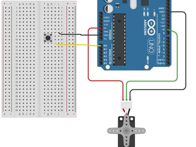
16 Controlling a Servo with a Potentiometer Time Required: 25 minutes In this project, we will be using a potentiometer to control the movement of our servo motor. When we twist our potentiometer knob, the servo will also rotate approximately the same amount. Remember, it doesn t matter what color the wires are in the diagram compared to the ones you use. Potentiometers are like a dynamic resistor, as you twist, the resistance value changes (this will make the voltage change from 0-5v). These changes in resistance is what our Arduino will read and convert into a number between What are the pins on the included Potentiometer? Positive Power Output: This pin can be connected to an Arduino. The Arduino will read the resistance value from the potentiometer. Ground A servo motor, is a special type of motor that can be used to rotate precisely. There is a sensor inside the motor that keeps track of how much it rotates. This allows us to tell the motor to rotate by degrees and it will stop at the correct location. 16

17 Required Components 1x Arduino 1x Breadboard 3x Jumper wires 1x potentiometer 1x Servo Motor Wiring 17

 Signal (tells Servo")
18 Diagrams for this project What are the pins on our Servo Motor? Ground Power (4.8-6v) Signal (tells Servo where to move) 18
19 Code Line 1. #include <Servo.h> Line 2. Line 3. const int servopin = 2; Line 4. const int userinputpin = A0; Line 5. Line 6. Servo myservo; Line 7. int pos = 0; Line 8. Line 9. void setup() { Line 10. Line 11. Line 12. Line 13. Line 14. Line 15. } Line 16. Line 17. void loop() { Line 18. myservo.attach(servopin); pinmode(userinputpin, INPUT); Line 19. pos = analogread(userinputpin); Line 20. Line 21. pos = map(pos, 0, 1023, 0, 180); Line 22. Line 23. Line 24. Line 25. Line 26. } myservo.write(pos); delay(100); Include the ability to use the Servo motor library (enables us to use the servo commands). Create two constant integer variables. Variable servopin will store the number 2, and userinputpin will store the number A0. Create a new servo called myservo. We give it a name since we could control more than one servo at a time. Create an integer variable with the value of 0. This will be used to store the position the servo should move to. Tell the Arduino to use (attach) the servopin (pin #2) to the servo called myservo. 19 Set the potentiometer that is connected to userinputpin (pin #A0) as an INPUT. Analog read the inputpin (A0), and store the value in our variable called pos. Map the raw sensor data (our sensor gives us a value between ) to a value between (0-255) and store the converted value back to the variable pos. Move the servo motor (called myservo) with the calculation we did previously stored in the variable servopos. Delay (pause) for 100 micoseconds. This will allow the servo motor to go to its position before being told to move again.

20 Creating a 30 Second Countdown Timer Time Required: 40 minutes In this project, we will be using a servo motor as a countdown timer. The Servo motor will rotate 3 degrees of movement for every second for a total of 30 seconds. We have a button that is connected to the Arduino so we can restart the 30 second timer when needed. Required Components 1x Arduino 1x Breadboard 5x Jumper Wires 1x Pushbutton 1x Servo Motor 20
21 Wiring 21
22 Code Line 1. Line 2. #include <Servo.h> Servo myservo; Include the ability to use the Servo motor library (enables us to use the servo commands). Create a new instance of a servo called myservo. We give it a name since we could control more than one servo at a time. Line 3. const int servopin = 9; Line 4. const int buttonpin = 2; Line 5. int servopos = 0; Line 6. int timercurvalue = 0; Line 7. const int timersetvalue = 30; Create a constant integer variable called servopin with a value of 9 (the pin the servo is using to be controlled). Create a constant integer variable called buttonpin with a value of 2 (the pin the button is connected to). Create an integer variable called servopos with a value of 0. This is used to store the position the servo should go. Create an integer variable called timercurvalue with a value of 0. This is used for how much time has elapsed. Create a constant integer variable called timersetvalue with a value of 30. This is used for how long we want the timer for. 22
23 Line 8. void setup() { Line 9. Line 10. Line 11. Line 12. myservo.attach(servopin); Serial.begin(9600); myservo.write(servopos); pinmode(buttonpin, INPUT_PULLUP); Tell the Arduino to use (attach) the servopin (pin #9) to the servo called myservo. Setup serial monitor at a baud rate (speed) of Set our servo (myservo) when the arduino turns on or restarts to the position at 0 degrees from the variable servopos. Set out button that is connected to buttonpin (pin #2) as an INPUT_PULLUP. Line 13. Line 14. } delay(2000); Wait two seconds before running the rest of our program. This will give our servo a moment to move to its 0 degree position if it needed to move. What is INPUT_PULLUP? When setting an Arduino Uno pin as INPUT_PULLUP this activates the internal 20kohm resistor in the processor. This allows us to connect a button to ground, then to the pin we want the button to be connected to on the Arduino without using a resistor. This however will reverse the logical of reading the button compared to using INPUT. When the button is not pressed the pin will read HIGH, and when the button is pressed it will read LOW. 23
24 Line 15. void loop() { Line 16. if(digitalread(buttonpin) == LOW) { Line 17. timercurvalue = 0; Line 18. Serial.println("*** TIMER RESTARTED ***"); Read if the button is pressed. Since the buttonpin (pin #2) is using INPUT_PULLUP instead of INPUT, the button pin will read LOW when pressed. When it is pressed reset the timer back to 0 and output the text *** TIMER RESTARTED *** in the serial monitor. Line 19. } Line 20. servopos = timercurvalue * 3; The timer starts at 0. Use the current elapsed time, multiple it by 3 and store this calculation in the variable servopos. This means for every second the servo will move 3 degrees. Line 21. Line 22. Serial.print("Timer: "); Serial.println(timerCurValue); Serial.print("Position: "); Serial.println(servoPos); Output through the serial monitor the current elapsed timer from the variable timercurvalue and output the current servo position from the variable servopos. 24
25 Line 23. Line 24. Serial.println(); myservo.write(servopos); Output a line break to our serial monitor. This is only to make it easier to read the outputs and is for aesthetics. Move the servo motor (called myservo) with the calculation we did previously stored in the variable servopos. Line 25. if (timercurvalue < timersetvalue) { Line 26. timercurvalue = timercurvalue + 1; If the current time (using our variable timercurvalue) is less than the set timer time (using the variable timersetvalue which is 30 seconds), increase the current time by one. Line 27. } Line 28. Line 29. } delay(1000); Wait one second before looping again. This makes it take one second to increase the timercurvalue variable by one and move the servo 3 degrees every second. 25
26 What is an H-Bridge? Time Required: < 15 minutes An H-Bridge is an electric integrated circuit that allows the ability to control up to two motors. These two motors can be independently controlled what direction it will spin. This could allow us to create a robot for example that could move forwards, backwards, turn left and turn right and have our Arduino program those movements. We are just using half the chip for all the projects, most of the pins on the left-hand side of the chip are for controlling a second motor. See the diagram on the next page for what each pin does from the H-Bridge. 26
27 This indented semicircle is used to indicate the top of the IC H-bridge chip 5v to power the IC chip. Ground connectors for the IC chip. Only one needs to be connected. Connect the positive and negative pins from the motor to the output. Input pins are used to control what direction the motor will spin. When you send 5v to input 4 for example only, then the motor will spin one direction. When you send 5v only to input 3 instead, the motor will spin the other direction. Positive voltage to power the motors 5-36v up to 600mA per motor. When you send 5v to this pin, it will allow the motor connected on the right side of the h-bridge to be enabled. 27
28 H-Bridge Controlled by an Arduino Time Required: 30 minutes In this project, we will be using an H-Bridge (Model L293D) connected with our Arduino to control the motor so it can rotate clockwise or counter clockwise. Pin #9 from our Arduino must output HIGH (output 5v) to enable the h-bridge to work. Pins #11 and pin #10 is used to control which direction the motor will turn. If you have pin #11 high (output 5v) the motor will spin one direction, while if you output high on pin #9 it will spin the other direction. The motor will not turn if both pin #10 and pin #11 is high (outputting 5volts) since you are telling the h-bridge to go clockwise and counter clockwise at the same time. This project will rotate the motor clockwise for 6 seconds, stop spinning the motor for 2 seconds, rotate the motor counterclockwise for 6 seconds, stop the motor for 2 seconds and then repeat forever. Required Components 1x Arduino 1x Breadboard 14x Jumper Wires 1x H-Bridge 1x DC Motor 28


29 Wiring This indented semicircle is used to indicate the top of the IC H-bridge chip. Make sure you put in the h-bridge correctly. 29
30 Code Line 1. void setup() { Line 2. pinmode(9, OUTPUT); Line 3. pinmode(10, OUTPUT); Line 4. pinmode(11, OUTPUT); Line 5. Line 6. digitalwrite(9, HIGH); Line 7. } Line 8. Line 9. void loop() { Line 10. Line 11. digitalwrite(10, HIGH); Line 12. digitalwrite(11, LOW); Line 13. delay(6000); Line 14. Line 15. digitalwrite(10, LOW); Line 16. digitalwrite(11, LOW); Line 17. delay(2000); Line 18. Line 19. digitalwrite(10, LOW); Line 20. digitalwrite(11, HIGH); Line 21. delay(6000); Line 22. Line 23. digitalwrite(10, LOW); Line 24. digitalwrite(11, LOW); Line 25. delay(2000); Line 26. } Set pin #9, pin #10 and pin #11 as an output When the Arduino turns on or restart, set pin #9 as HIGH (on). This pin will be used to tell the h-bridge to be enabled. We did it in the setup since we never need to turn it off later Set pin #10 to HIGH (on) and pin #11 to LOW (off) and then wait for 6 seconds. This will spin the motor one direction Set pin #10 to LOW (off) and pin #11 to LOW (off) and then wait for 2 seconds. This will stop the motor from spinning. Set pin #10 to LOW (off) and pin #11 to HIGH (on) and then wait for 6 seconds. This will spin the motor in the opposite direction. Set pin #10 to LOW (off) and pin #11 to LOW (off) and then wait for 2 seconds. This will stop the motor from spinning. 30
31 H-Bridge Using Potentiometer Time Required: 50 minutes In this project, we will using an H-Bridge (Model L293D) with an Arduino to control the direction of the rotation of the motor based on the position of the potentiometer. Pin #9 from our Arduino will be used to control the speed of the motor attached (output 5v). Pins #11 and pin #10 is used to control which direction the motor will turn. If you have pin #11 high (output 5v) the motor will spin one direction, while if you output high on pin #10 it will spin the other direction. The motor will not turn if both pin #10 and pin #11 is high (outputting 5v) since you telling the h-bridge to go clockwise and counter clockwise at the same time. The potentiometer will be used at the 12 o clock position to stop all motor movement. If you turn the potentiometer counterclockwise, the motor will spin in that direction as well. If you turn the potentiometer clockwise the motor will spin in the direction as well. As you rotate the potentiometer more and more clockwise or counterclockwise, the motor will increase in speed until you reached the limit of how far it can move in either direction. Required Components 1x Arduino 1x Breadboard 12x Jumper Wires 1x Potentiometer 1x H-Bridge 1x DC Motor 31

32 The above diagram above is used to illustrate the movement of the motor when you rotate the potentiometer for this project. 32

33 Wiring This indented semicircle is used to indicate the top of the IC H- bridge chip. 33
34 Code Line 1. const int motorenpin = 9; Line 2. const int motorfwdpin = 10; Line 3. const int motorbkwdpin = 11; Line 4. Line 5. const int potinputpin = A0; Line 6. int inputvalue = 0; Line 7. int motorspeed = 0; Line 8. Create a constant integer variable called motorenpin with a value of 9 (the pin to enable the h-bridge to turn on). Create a constant integer variable called motorfwdpin with a value of 10 (the pin is used to tell the h-bridge to move the motor clockwise). Create a constant integer variable called motobkwdpin with a value of 11 (the pin is used to tell the h-bridge to move the motor counterclockwise). Create a constant integer variable called potinputpin with a value of A0 (the pin is used to read the value from the potentiometer). Create an integer variable called inputvalue with a value of 0 (this will be used to store the current value of our potentiometer). Create an integer variable called motorspeed with a value of 0 (this will be used to store the current value of how fast the motor should spin). Line 9. void setup() { Line 10. Line 11. Line 12. Line 13. Line 14. pinmode(motorenpin, OUTPUT); pinmode(motorfwdpin, OUTPUT); pinmode(motorbkwdpin, OUTPUT); pinmode(potinputpin, INPUT); Set our pins for motorenpin (pin #9), motorfwdpin (pin #10), motorbkwdpin (pin #11) as an OUTPUT. Set the potentiometer that is connected to potinputpin (pin #A0) as an INPUT. 34
35 Line 15. Line 16. } Serial.begin(9600); Start serial communication when the Arduino boots. Set the communication speed to 9600 baud. Line 17. void loop() { Line 18. inputvalue = analogread(potinputpin); Store the value from the potentiometer using analogread for the potinputpin (#A0) into the variable inputvalue. Line 19. Line 20. if(inputvalue >= 0 & inputvalue <= 472) { Line 21. Line 22. Line 23. Serial.println("Clockwise"); digitalwrite(motorfwdpin, HIGH); digitalwrite(motorbkwdpin, LOW); Line 24. motorspeed = map(inputvalue, 0, 472, 255, 0); Line 25. } Line 26. else if(inputvalue >= 552 & inputvalue <= 1023) { Line 27. Line 28. Line 29. Serial.println("Counterclockwise"); digitalwrite(motorfwdpin, LOW); digitalwrite(motorbkwdpin, HIGH); Line 30. motorspeed = map(inputvalue, 552, 1023, 0, 255); Line 31. } 35 When the potentiometer knob input is between 0 472, output the Serial message Clockwise, set the motorfwdpin to HIGH and the motorbkwdpin to LOW (this will make the H-Bridge be told to go clockwise). Store the calculated speed for the motor to spin using the variable motorspeed. We use the map function to read the potentiometer so that when the knob is reading 0, the speed will be 255 (speed is a value between 0-255). When the potentiometer is reading 472, set the motor speed to 0. It will then calculate automatically the motor speed to adjust smoothly with the input from the potentiometer. When the potentiometer knob input is between , output the Serial message Counterclockwise, set the motorfwdpin to LOW and the motorbkwdpin to HIGH (this will make the H-Bridge be told to go counterclockwise). Store the calculated speed for the motor to spin using the variable motorspeed. We use the map function to read the potentiometer so that when the knob is reading 552, the speed will be 0 (speed is a value between 0-255). When the potentiometer is reading 1023, set the motor speed to 255. It will then calculate automatically the motor speed to adjust smoothly with the input from the potentiometer.
36 Line 32. else { Line 33. Serial.println("Stop"); Line 34. digitalwrite(motorfwdpin, LOW); Line 35. digitalwrite(motorbkwdpin, LOW); Line 36. motorspeed = 0; Line 37. } Line 38. Serial.print("Input: "); Line 39. Serial.println(inputValue); Line 40. Line 41. Serial.print("Speed: "); Line 42. Serial.println(motorSpeed); Line 43. Line 44. analogwrite(motorenpin, motorspeed); Line 45. Any other value for the potentiometer knob input (which would be between ), output the Serial message Stop, set the motorfwdpin to LOW and the motorbkwdpin to LOW (this will make the H-Bridge be told to stop moving the motor). Set the speed for the motor to 0. Output the serial message Input:, and then output on the same line the contents of the variable from the inputvalue. Since we are using println, this will create a line break after output the contents of that variable. Output the serial message Speed:, and then output on the same line the contents of the variable from the motorspeed. Since we are using println, this will create a line break after output the contents of that variable. Set the speed of the motor. This is done by using analogwrite to the motorenpin (pin #9, which is connected to the h-bridge from that pin) outputting the number stored in motorspeed. Line 46. delay(100); Create a delay for 100 microseconds only so we can slow down the serial text output to make it easier to read. 36

37 Recommended Resources Get these for free at the Toronto Public Library Want to learn more about Arduinos? Here is a list of our favorite Toronto Public Library books and resources. When using the Arduino Kit, please stick to the projects outlined in this manual. Additional projects found in the recommended resources are for educational and entertainment purposes and are only intended for use with your personal Arduino. The official website has great tutorials and reference resources. The website includes information on all commands you can do for the Arduino programming language and examples on how to use them. 37
.")

38 Learning Arduino with Peggy Fisher This beginner course consists of two hours of video and can be accessed for free from Lynda.com (via tpl.ca/elearning with a valid Toronto Public Library card). Adventures in Arduino by Becky Stewart This book provides simple, easy-to-follow introductions to the Arduino. It is written for 11 to 15 year olds, but we ve found the concepts, content, and language engaging and applicable to adult Arduino users. Available from Safari (via tpl.ca/elearning with a valid Toronto Public Library card). 38
.")

39 Arduino for Kids (2017) by Priya Kuber, Rishi Gaurav Bhatnagar, Vijay Varada This book is intended for children (ages 9 and up) and their parents. It includes a series of fun, easy projects that don t require any knowledge of electronics. Available from Safari (via tpl.ca/elearning with a valid Toronto Public Library card). The Maker's Guide to the Zombie Apocalypse: Defend Your Base with Simple Circuits, Arduino, and Raspberry Pi (2016) by Simon Monk No one knows what the future holds, so we can t definitively say whether or not the Arduino projects in this book will come in handy. What we can guarantee is that you ll have fun learning about Arduinos in a unique and creative way. Available in regular print. 39

 by Derek Runberg and Brian Huang Ready to move on from the Arduino kits and start working on some more advanced projects?")
40 Make: Drones: Teach an Arduino to Fly by David McGriffy Have you ever wondered how drones work? This book reveals drone building secrets and explains how you can get your Arduino to fly. Available in regular print and as an ebook from Safari (via tpl.ca/elearning with a valid Toronto Public Library card). The Arduino Inventor's Guide (2017) by Derek Runberg and Brian Huang Ready to move on from the Arduino kits and start working on some more advanced projects? Why not build a tiny electric piano, a desktop greenhouse, or a colour-mixing night light? You ll find ten fun Arduino projects in this new ebook, available from Safari (via tpl.ca/elearning with a valid Toronto Public Library card) 40

41 Arduino Playground : Geeky Projects for the Experienced Maker (2017) by Warren Andrews This is the perfect resource for more advanced Arduino projects. One of our favourites is the Garage Sentry Parking Assistant, a project that can help you pull into your garage by setting off an alarm when you ve gone far enough and need to hit the brakes. Available in regular print and as an ebook from Safari (via tpl.ca/elearning with a valid Toronto Public Library card) 41
Arduino Intermediate Projects
 Arduino Intermediate Projects Created as a companion manual to the Toronto Public Library Arduino Kits. Arduino Intermediate Projects Copyright 2018 Toronto Public Library. All rights reserved. Published
For this exercise, you will need a partner, an Arduino kit (in the plastic tub), and a laptop with the Arduino programming environment.
, and a laptop with the Arduino programming environment.") Physics 222 Name: Exercise 6: Mr. Blinky This exercise is designed to help you wire a simple circuit based on the Arduino microprocessor, which is a particular brand of microprocessor that also includes
Physics 222 Name: Exercise 6: Mr. Blinky This exercise is designed to help you wire a simple circuit based on the Arduino microprocessor, which is a particular brand of microprocessor that also includes
Lab 06: Ohm s Law and Servo Motor Control
 CS281: Computer Systems Lab 06: Ohm s Law and Servo Motor Control The main purpose of this lab is to build a servo motor control circuit. As with prior labs, there will be some exploratory sections designed
Arduino and Servo Motor
 Arduino and Servo Motor 1. Basics of the Arduino Board and Arduino a. Arduino is a mini computer that can input and output data using the digital and analog pins b. Arduino Shield: mounts on top of Arduino
Rodni What will yours be?
 Rodni What will yours be? version 4 Welcome to Rodni, a modular animatronic animal of your own creation for learning how easy it is to enter the world of software programming and micro controllers. During
Coding with Arduino to operate the prosthetic arm
 Setup Board Install FTDI Drivers This is so that your RedBoard will be able to communicate with your computer. If you have Windows 8 or above you might already have the drivers. 1. Download the FTDI driver
Objectives: Learn what an Arduino is and what it can do Learn what an LED is and how to use it Be able to wire and program an LED to blink
 Objectives: Learn what an Arduino is and what it can do Learn what an LED is and how to use it Be able to wire and program an LED to blink By the end of this session: You will know how to use an Arduino
100UF CAPACITOR POTENTIOMETER SERVO MOTOR MOTOR ARM. MALE HEADER PIN (3 pins) INGREDIENTS
 INGREDIENTS") 05 POTENTIOMETER SERVO MOTOR MOTOR ARM 100UF CAPACITOR MALE HEADER PIN (3 pins) INGREDIENTS 63 MOOD CUE USE A SERVO MOTOR TO MAKE A MECHANICAL GAUGE TO POINT OUT WHAT SORT OF MOOD YOU RE IN THAT DAY Discover:
05 POTENTIOMETER SERVO MOTOR MOTOR ARM 100UF CAPACITOR MALE HEADER PIN (3 pins) INGREDIENTS 63 MOOD CUE USE A SERVO MOTOR TO MAKE A MECHANICAL GAUGE TO POINT OUT WHAT SORT OF MOOD YOU RE IN THAT DAY Discover:
Learning Objectives. References 10/26/11. Using servos with an Arduino. EAS 199A Fall 2011
 Using servos with an Arduino EAS 199A Fall 2011 Learning Objectives Be able to identify characteristics that distinguish a servo and a DC motor Be able to describe the difference a conventional servo and
Using Servos with an Arduino
 Using Servos with an Arduino ME 120 Mechanical and Materials Engineering Portland State University http://web.cecs.pdx.edu/~me120 Learning Objectives Be able to identify characteristics that distinguish
Computational Crafting with Arduino. Christopher Michaud Marist School ECEP Programs, Georgia Tech
 Computational Crafting with Arduino Christopher Michaud Marist School ECEP Programs, Georgia Tech Introduction What do you want to learn and do today? Goals with Arduino / Computational Crafting Purpose
CURIE Academy, Summer 2014 Lab 2: Computer Engineering Software Perspective Sign-Off Sheet
 Lab : Computer Engineering Software Perspective Sign-Off Sheet NAME: NAME: DATE: Sign-Off Milestone TA Initials Part 1.A Part 1.B Part.A Part.B Part.C Part 3.A Part 3.B Part 3.C Test Simple Addition Program
The Motor sketch. One Direction ON-OFF DC Motor
 One Direction ON-OFF DC Motor The DC motor in your Arduino kit is the most basic of electric motors and is used in all types of hobby electronics. When current is passed through, it spins continuously
FABO ACADEMY X ELECTRONIC DESIGN
 ELECTRONIC DESIGN MAKE A DEVICE WITH INPUT & OUTPUT The Shanghaino can be programmed to use many input and output devices (a motor, a light sensor, etc) uploading an instruction code (a program) to it
Lesson 3: Arduino. Goals
 Introduction: This project introduces you to the wonderful world of Arduino and how to program physical devices. In this lesson you will learn how to write code and make an LED flash. Goals 1 - Get to
Arduino Control of Tetrix Prizm Robotics. Motors and Servos Introduction to Robotics and Engineering Marist School
 Arduino Control of Tetrix Prizm Robotics Motors and Servos Introduction to Robotics and Engineering Marist School Motor or Servo? Motor Faster revolution but less Power Tetrix 12 Volt DC motors have a
Lab 2: Blinkie Lab. Objectives. Materials. Theory
 Lab 2: Blinkie Lab Objectives This lab introduces the Arduino Uno as students will need to use the Arduino to control their final robot. Students will build a basic circuit on their prototyping board and
Programming 2 Servos. Learn to connect and write code to control two servos.
 Programming 2 Servos Learn to connect and write code to control two servos. Many students who visit the lab and learn how to use a Servo want to use 2 Servos in their project rather than just 1. This lesson
Assignments from last week
 Assignments from last week Review LED flasher kits Review protoshields Need more soldering practice (see below)? http://www.allelectronics.com/make-a-store/category/305/kits/1.html http://www.mpja.com/departments.asp?dept=61
Mechatronics Engineering and Automation Faculty of Engineering, Ain Shams University MCT-151, Spring 2015 Lab-4: Electric Actuators
 Mechatronics Engineering and Automation Faculty of Engineering, Ain Shams University MCT-151, Spring 2015 Lab-4: Electric Actuators Ahmed Okasha, Assistant Lecturer okasha1st@gmail.com Objective Have a
Lecture 4: Basic Electronics. Lecture 4 Brief Introduction to Electronics and the Arduino
 Lecture 4: Basic Electronics Lecture 4 Page: 1 Brief Introduction to Electronics and the Arduino colintan@nus.edu.sg Lecture 4: Basic Electronics Page: 2 Objectives of this Lecture By the end of today
Parts List. Robotic Arm segments ¼ inch screws Cable XBEE module or Wifi module
 Robotic Arm 1 Legal Stuff Stensat Group LLC assumes no responsibility and/or liability for the use of the kit and documentation. There is a 90 day warranty for the Sten-Bot kit against component defects.
Disclaimer. Arduino Hands-On 2 CS5968 / ART4455 9/1/10. ! Many of these slides are mine. ! But, some are stolen from various places on the web
 Arduino Hands-On 2 CS5968 / ART4455 Disclaimer! Many of these slides are mine! But, some are stolen from various places on the web! todbot.com Bionic Arduino and Spooky Arduino class notes from Tod E.Kurt!
J. La Favre Using Arduino with Raspberry Pi February 7, 2018
 As you have already discovered, the Raspberry Pi is a very capable digital device. Nevertheless, it does have some weaknesses. For example, it does not produce a clean pulse width modulation output (unless
LED + Servo 2 devices, 1 Arduino
 LED + Servo 2 devices, 1 Arduino Learn to connect and write code to control both a Servo and an LED at the same time. Many students who come through the lab ask if they can use both an LED and a Servo
Attribution Thank you to Arduino and SparkFun for open source access to reference materials.
 Attribution Thank you to Arduino and SparkFun for open source access to reference materials. Contents Parts Reference... 1 Installing Arduino... 7 Unit 1: LEDs, Resistors, & Buttons... 7 1.1 Blink (Hello
MAKEVMA502 BASIC DIY KIT WITH ATMEGA2560 FOR ARDUINO USER MANUAL
 BASIC DIY KIT WITH ATMEGA2560 FOR ARDUINO USER MANUAL USER MANUAL 1. Introduction To all residents of the European Union Important environmental information about this product This symbol on the device
Lecture 6. Interfacing Digital and Analog Devices to Arduino. Intro to Arduino
 Lecture 6 Interfacing Digital and Analog Devices to Arduino. Intro to Arduino PWR IN USB (to Computer) RESET SCL\SDA (I2C Bus) POWER 5V / 3.3V / GND Analog INPUTS Digital I\O PWM(3, 5, 6, 9, 10, 11) Components
Analog Feedback Servos
 Analog Feedback Servos Created by Bill Earl Last updated on 2018-01-21 07:07:32 PM UTC Guide Contents Guide Contents About Servos and Feedback What is a Servo? Open and Closed Loops Using Feedback Reading
UNIT 4 VOCABULARY SKILLS WORK FUNCTIONS QUIZ. A detailed explanation about Arduino. What is Arduino? Listening
 UNIT 4 VOCABULARY SKILLS WORK FUNCTIONS QUIZ 4.1 Lead-in activity Find the missing letters Reading A detailed explanation about Arduino. What is Arduino? Listening To acquire a basic knowledge about Arduino
MICROCONTROLLERS BASIC INPUTS and OUTPUTS (I/O)
") PH-315 Portland State University MICROCONTROLLERS BASIC INPUTS and OUTPUTS (I/O) ABSTRACT A microcontroller is an integrated circuit containing a processor and programmable read-only memory, 1 which is
PH-315 Portland State University MICROCONTROLLERS BASIC INPUTS and OUTPUTS (I/O) ABSTRACT A microcontroller is an integrated circuit containing a processor and programmable read-only memory, 1 which is
HAW-Arduino. Sensors and Arduino F. Schubert HAW - Arduino 1
 HAW-Arduino Sensors and Arduino 14.10.2010 F. Schubert HAW - Arduino 1 Content of the USB-Stick PDF-File of this script Arduino-software Source-codes Helpful links 14.10.2010 HAW - Arduino 2 Report for
Arduino STEAM Academy Arduino STEM Academy Art without Engineering is dreaming. Engineering without Art is calculating. - Steven K.
 Arduino STEAM Academy Arduino STEM Academy Art without Engineering is dreaming. Engineering without Art is calculating. - Steven K. Roberts Page 1 See Appendix A, for Licensing Attribution information
Arduino Digital Out_QUICK RECAP
 Arduino Digital Out_QUICK RECAP BLINK File> Examples>Digital>Blink int ledpin = 13; // LED connected to digital pin 13 // The setup() method runs once, when the sketch starts void setup() // initialize
EE-110 Introduction to Engineering & Laboratory Experience Saeid Rahimi, Ph.D. Labs Introduction to Arduino
 EE-110 Introduction to Engineering & Laboratory Experience Saeid Rahimi, Ph.D. Labs 10-11 Introduction to Arduino In this lab we will introduce the idea of using a microcontroller as a tool for controlling
Inspiring Creative Fun Ysbrydoledig Creadigol Hwyl. S4A - Scratch for Arduino Workbook
 Inspiring Creative Fun Ysbrydoledig Creadigol Hwyl S4A - Scratch for Arduino Workbook 1) Robotics Draw a robot. Consider the following and annotate: What will it look like? What will it do? How will you
Sten-Bot Robot Kit Stensat Group LLC, Copyright 2013
 Sten-Bot Robot Kit Stensat Group LLC, Copyright 2013 Legal Stuff Stensat Group LLC assumes no responsibility and/or liability for the use of the kit and documentation. There is a 90 day warranty for the
Project 27 Joystick Servo Control
 Project 27 Joystick Servo Control For another simple project, let s use a joystick to control the two servos. You ll arrange the servos in such a way that you get a pan-tilt head, such as is used for CCTV
HOW TO BUILD A CAR PARK WITH INTEL GALILEO!
 HOW TO BUILD A CAR PARK WITH INTEL GALILEO! A step by step tutorial to build, in a very simple way, a funny car park with automatic barrier and display counter with your Intel Galileo!» Recommended age
Arduino Lesson 1. Blink. Created by Simon Monk
 Arduino Lesson 1. Blink Created by Simon Monk Guide Contents Guide Contents Overview Parts Part Qty The 'L' LED Loading the 'Blink' Example Saving a Copy of 'Blink' Uploading Blink to the Board How 'Blink'
Servo Sweep. Learn to make a regular Servo move in a sweeping motion.
 Servo Sweep Learn to make a regular Servo move in a sweeping motion. We have seen how to control a Servo and also how to make an LED Fade on and off. This activity will teach you how to make a regular
Digital Electronics & Chip Design
 Digital Electronics & Chip Design Lab Manual I: The Utility Board 1999 David Harris The objective of this lab is to assemble your utility board. This board, containing LED displays, switches, and a clock,
Breadboard Primer. Experience. Objective. No previous electronics experience is required.
 Breadboard Primer Experience No previous electronics experience is required. Figure 1: Breadboard drawing made using an open-source tool from fritzing.org Objective A solderless breadboard (or protoboard)
Programmable Control Introduction
 Programmable Control Introduction By the end of this unit you should be able to: Give examples of where microcontrollers are used Recognise the symbols for different processes in a flowchart Construct
Programming a Servo. Servo. Red Wire. Black Wire. White Wire
 Programming a Servo Learn to connect wires and write code to program a Servo motor. If you have gone through the LED Circuit and LED Blink exercises, you are ready to move on to programming a Servo. A
Bill of Materials: PWM Stepper Motor Driver PART NO
 PWM Stepper Motor Driver PART NO. 2183816 Control a stepper motor using this circuit and a servo PWM signal from an R/C controller, arduino, or microcontroller. Onboard circuitry limits winding current,
Arduino An Introduction
 Arduino An Introduction Hardware and Programming Presented by Madu Suthanan, P. Eng., FEC. Volunteer, Former Chair (2013-14) PEO Scarborough Chapter 2 Arduino for Mechatronics 2017 This note is for those
Name & SID 1 : Name & SID 2:
 EE40 Final Project-1 Smart Car Name & SID 1 : Name & SID 2: Introduction The final project is to create an intelligent vehicle, better known as a robot. You will be provided with a chassis(motorized base),
Lab Exercise 9: Stepper and Servo Motors
 ME 3200 Mechatronics Laboratory Lab Exercise 9: Stepper and Servo Motors Introduction In this laboratory exercise, you will explore some of the properties of stepper and servomotors. These actuators are
A servo is an electric motor that takes in a pulse width modulated signal that controls direction and speed. A servo has three leads:
 Project 4: Arduino Servos Part 1 Description: A servo is an electric motor that takes in a pulse width modulated signal that controls direction and speed. A servo has three leads: a. Red: Current b. Black:
TWEAK THE ARDUINO LOGO
 TWEAK THE ARDUINO LOGO Using serial communication, you'll use your Arduino to control a program on your computer Discover : serial communication with a computer program, Processing Time : 45 minutes Level
MICROCONTROLLERS BASIC INPUTS and OUTPUTS (I/O)
") PH-315 Portland State University MICROCONTROLLERS BASIC INPUTS and OUTPUTS (I/O) ABSTRACT A microcontroller is an integrated circuit containing a processor and programmable read-only memory, 1 which is
PH-315 Portland State University MICROCONTROLLERS BASIC INPUTS and OUTPUTS (I/O) ABSTRACT A microcontroller is an integrated circuit containing a processor and programmable read-only memory, 1 which is
Blue Point Engineering
 Blue Point Engineering Instruction I www.bpesolutions.com Pointing the Way to Solutions! Animatronic Wizard - 3 Board (BPE No. WAC-0030) Version 3.0 2009 Controller Page 1 The Wizard 3 Board will record
Two Hour Robot. Lets build a Robot.
 Lets build a Robot. Our robot will use an ultrasonic sensor and servos to navigate it s way around a maze. We will be making 2 voltage circuits : A 5 Volt for our ultrasonic sensor, sound and lights powered
Getting Started with the micro:bit
 Page 1 of 10 Getting Started with the micro:bit Introduction So you bought this thing called a micro:bit what is it? micro:bit Board DEV-14208 The BBC micro:bit is a pocket-sized computer that lets you
Arduino Sensor Beginners Guide
 Arduino Sensor Beginners Guide So you want to learn arduino. Good for you. Arduino is an easy to use, cheap, versatile and powerful tool that can be used to make some very effective sensors. This guide
Nano v3 pinout 19 AUG ver 3 rev 1.
 Nano v3 pinout NANO PINOUT www.bq.com 19 AUG 2014 ver 3 rev 1 Nano v3 Schematic Reserved Words Standard Arduino ( C / C++ ) Reserved Words: int byte boolean char void unsigned word long short float double
4WD Mobile Platform SKU:ROB0022
 4WD Mobile Platform SKU:ROB0022 Contents [hide] 1 Function Introduction 1.1 STEP1: Assemble Robot 1.2 STEP2: Debug Motor 1.3 STEP3:Install Upper Plate 1.4 STEP4: Debug Ultrasonic Sensor and Servo 1.5 STEP5:
Simple Servo USER Instructions
 Simple Servo USER Instructions Version 1V2 Copyright 2003-2007 Active Robots Limited 10A New Rock Ind. Est., Newrock, Chilcompton, Somerset BA3 4JE UK Tel: +44(0)1761 239 267 Fax: +44(0)176 123 3162 www.active-robots.com
PLAN DE FORMACIÓN EN LENGUAS EXTRANJERAS IN-57 Technology for ESO: Contents and Strategies
 Lesson Plan: Traffic light with Arduino using code, S4A and Ardublock Course 3rd ESO Technology, Programming and Robotic David Lobo Martínez David Lobo Martínez 1 1. TOPIC Arduino is an open source hardware
Pulse Width Modulation and
 Pulse Width Modulation and analogwrite ( ); 28 Materials needed to wire one LED. Odyssey Board 1 dowel Socket block Wire clip (optional) 1 Female to Female (F/F) wire 1 F/F resistor wire LED Note: The
DFRduino Romeo All in one Controller V1.1(SKU:DFR0004)
") DFRduino Romeo All in one Controller V1.1(SKU:DFR0004) DFRduino RoMeo V1.1 Contents 1 Introduction 2 Specification 3 DFRduino RoMeo Pinout 4 Before you start 4.1 Applying Power 4.2 Software 5 Romeo Configuration
DFRduino Romeo All in one Controller V1.1(SKU:DFR0004) DFRduino RoMeo V1.1 Contents 1 Introduction 2 Specification 3 DFRduino RoMeo Pinout 4 Before you start 4.1 Applying Power 4.2 Software 5 Romeo Configuration
Parts to be supplied by the student: Breadboard and wires IRLZ34N N-channel enhancement-mode power MOSFET transistor
 University of Utah Electrical & Computer Engineering Department ECE 1250 Lab 3 Electronic Speed Control and Pulse Width Modulation A. Stolp, 12/31/12 Rev. Objectives 1 Introduce the Oscilloscope and learn
Pi-Cars Factory Tool Kit
 Pi-Cars Factory Tool Kit Posted on January 24, 2013 Welcome to the factory: Welcome to where you will learn how to build a Pi-Car, we call it the Pi-Cars Factory. We hope that this page contains all you
Intelligent Systems Design in a Non Engineering Curriculum. Embedded Systems Without Major Hardware Engineering
 Intelligent Systems Design in a Non Engineering Curriculum Embedded Systems Without Major Hardware Engineering Emily A. Brand Dept. of Computer Science Loyola University Chicago eabrand@gmail.com William
1. Controlling the DC Motors
 E11: Autonomous Vehicles Lab 5: Motors and Sensors By this point, you should have an assembled robot and Mudduino to power it. Let s get things moving! In this lab, you will write code to test your motors
INSTANT ROBOT SHIELD (AXE408)
") INSTANT ROBOT SHIELD (AXE408) 1.0 Introduction Thank you for purchasing this Instant Robot shield. This datasheet is designed to give a brief introduction to how the shield is assembled, used and configured.
INSTANT ROBOT SHIELD (AXE408) 1.0 Introduction Thank you for purchasing this Instant Robot shield. This datasheet is designed to give a brief introduction to how the shield is assembled, used and configured.
Arduino Programming Part 3
 Arduino Programming Part 3 EAS 199A Fall 2011 Overview Part I Circuits and code to control the speed of a small DC motor. Use potentiometer for dynamic user input. Use PWM output from Arduino to control
Part (A) Using the Potentiometer and the ADC* Part (B) LEDs and Stepper Motors with Interrupts* Part (D) Breadboard PIC Running a Stepper Motor
 Using the Potentiometer and the ADC* Part (B) LEDs and Stepper Motors with Interrupts* Part (D) Breadboard PIC Running a Stepper Motor") Name Name (Most parts are team so maintain only 1 sheet per team) ME430 Mechatronic Systems: Lab 5: ADC, Interrupts, Steppers, and Servos The lab team has demonstrated the following tasks: Part (A) Using
Name Name (Most parts are team so maintain only 1 sheet per team) ME430 Mechatronic Systems: Lab 5: ADC, Interrupts, Steppers, and Servos The lab team has demonstrated the following tasks: Part (A) Using
Workshop 9: First steps in electronics
 King s Maths School Robotics Club Workshop 9: First steps in electronics 1 Getting Started Make sure you have everything you need to complete this lab: Arduino for power supply breadboard black, red and
Lab 5: Arduino Uno Microcontroller Innovation Fellows Program Bootcamp Prof. Steven S. Saliterman
 Lab 5: Arduino Uno Microcontroller Innovation Fellows Program Bootcamp Prof. Steven S. Saliterman Exercise 5-1: Familiarization with Lab Box Contents Objective: To review the items required for working
CONSTRUCTION GUIDE Capacitor, Transistor & Motorbike. Robobox. Level VII
 CONSTRUCTION GUIDE Capacitor, Transistor & Motorbike Robobox Level VII Capacitor, Transistor & Motorbike In this box, we will understand in more detail the operation of DC motors, transistors and capacitor.
Introduction to. An Open-Source Prototyping Platform. Hans-Petter Halvorsen
 Introduction to An Open-Source Prototyping Platform Hans-Petter Halvorsen Contents 1.Overview 2.Installation 3.Arduino Starter Kit 4.Arduino TinkerKit 5.Arduino Examples 6.LabVIEW Interface for Arduino
Experiment #3: Micro-controlled Movement
 Experiment #3: Micro-controlled Movement So we re already on Experiment #3 and all we ve done is blinked a few LED s on and off. Hang in there, something is about to move! As you know, an LED is an output
2.017 DESIGN OF ELECTROMECHANICAL ROBOTIC SYSTEMS Fall 2009 Lab 4: Motor Control. October 5, 2009 Dr. Harrison H. Chin
 2.017 DESIGN OF ELECTROMECHANICAL ROBOTIC SYSTEMS Fall 2009 Lab 4: Motor Control October 5, 2009 Dr. Harrison H. Chin Formal Labs 1. Microcontrollers Introduction to microcontrollers Arduino microcontroller
1 Day Robot Building (MC40A + Aluminum Base) for Edubot 2.0
 for Edubot 2.0") 1 Day Robot Building (MC40A + Aluminum Base) for Edubot 2.0 Have you ever thought of making a mobile robot in 1 day? Now you have the chance with MC40A Mini Mobile Robot Controller + some accessories.
1 Day Robot Building (MC40A + Aluminum Base) for Edubot 2.0 Have you ever thought of making a mobile robot in 1 day? Now you have the chance with MC40A Mini Mobile Robot Controller + some accessories.
Arduino Microcontroller Processing for Everyone!: Third Edition / Steven F. Barrett
 Arduino Microcontroller Processing for Everyone!: Third Edition / Steven F. Barrett Anatomy of a Program Programs written for a microcontroller have a fairly repeatable format. Slight variations exist
Microcontrollers and Interfacing
 Microcontrollers and Interfacing Week 07 digital input, debouncing, interrupts and concurrency College of Information Science and Engineering Ritsumeikan University 1 this week digital input push-button
CONSTRUCTION GUIDE Robotic Arm. Robobox. Level II
 CONSTRUCTION GUIDE Robotic Arm Robobox Level II Robotic Arm This month s robot is a robotic arm with two degrees of freedom that will teach you how to use motors. You will then be able to move the arm
Motors and Servos Part 2: DC Motors
 Motors and Servos Part 2: DC Motors Back to Motors After a brief excursion into serial communication last week, we are returning to DC motors this week. As you recall, we have already worked with servos
.:Twisting:..:Potentiometers:.
 CIRC-08.:Twisting:..:Potentiometers:. WHAT WE RE DOING: Along with the digital pins, the also has 6 pins which can be used for analog input. These inputs take a voltage (from 0 to 5 volts) and convert
Saturday Academy Program
 Lesson Plans High School Courses Donald L. McCoy K-to-College STEM Education Consultant thempitman@gmail.com Last Update: October 17, 2018 Virtual Reality Coding using PlayCanvas RobotC Coding Applications
APDS-9960 RGB and Gesture Sensor Hookup Guide
 Page 1 of 12 APDS-9960 RGB and Gesture Sensor Hookup Guide Introduction Touchless gestures are the new frontier in the world of human-machine interfaces. By swiping your hand over a sensor, you can control
Experiment 4.B. Position Control. ECEN 2270 Electronics Design Laboratory 1
 Experiment 4.B Position Control Electronics Design Laboratory 1 Procedures 4.B.1 4.B.2 4.B.3 4.B.4 Read Encoder with Arduino Position Control by Counting Encoder Pulses Demo Setup Extra Credit Electronics
Breadboard Arduino Compatible Assembly Guide
 (BBAC) breadboard arduino compatible Breadboard Arduino Compatible Assembly Guide (BBAC) A Few Words ABOUT THIS KIT The overall goal of this kit is fun. Beyond this, the aim is to get you comfortable using
Arduino. AS220 Workshop. Part II Interactive Design with advanced Transducers Lutz Hamel
 AS220 Workshop Part II Interactive Design with advanced Transducers Lutz Hamel hamel@cs.uri.edu www.cs.uri.edu/~hamel/as220 How we see the computer Image source: Considering the Body, Kate Hartman, 2008.
40 Amp Digital Bidirectional PWM Motor Controller with Regenerative Braking BIDIR-340-DR
 40 Amp Digital Bidirectional PWM Motor Controller with Regenerative Braking BIDIR-340-DR The BIDIR-340-DR is a fully solid-state motor controller that allows you to control the speed and direction of a
Internet of Things Student STEM Project Jackson High School. Lesson 3: Arduino Solar Tracker
 Internet of Things Student STEM Project Jackson High School Lesson 3: Arduino Solar Tracker Lesson 3 Arduino Solar Tracker Time to complete Lesson 60-minute class period Learning objectives Students learn
VMA435 DIGITAL ROTARY ENCODER MODULE USER MANUAL
 DIGITAL ROTARY ENCODER MODULE USER MANUAL USER MANUAL 1. Introduction To all residents of the European Union Important environmental information about this product This symbol on the device or the package
Touch Potentiometer Hookup Guide
 Page 1 of 14 Touch Potentiometer Hookup Guide Introduction The Touch Potentiometer, or Touch Pot for short, is an intelligent, linear capacitive touch sensor that implements potentiometer functionality
Module: Arduino as Signal Generator
 Name/NetID: Teammate/NetID: Module: Laboratory Outline In our continuing quest to access the development and debugging capabilities of the equipment on your bench at home Arduino/RedBoard as signal generator.
Circuit Board Assembly Instructions for Babuinobot 1.0
 Circuit Board Assembly Instructions for Babuinobot 1.0 Brett Nelson January 2010 1 Features Sensor4 input Sensor3 input Sensor2 input 5v power bus Sensor1 input Do not exceed 5v Ground power bus Programming
Setup Download the Arduino library (link) for Processing and the Lab 12 sketches (link).
 for Processing and the Lab 12 sketches (link).") Lab 12 Connecting Processing and Arduino Overview In the previous lab we have examined how to connect various sensors to the Arduino using Scratch. While Scratch enables us to make simple Arduino programs,
Lab 12 Connecting Processing and Arduino Overview In the previous lab we have examined how to connect various sensors to the Arduino using Scratch. While Scratch enables us to make simple Arduino programs,
MILL ONE. Assembly Manual. Manual Illustrated by Gontarz Design Studio
 MILL ONE Assembly Manual Manual Illustrated by Gontarz Design Studio Safety Warnings and Guidelines 1. Be sure to carefully follow provided machine assembly instructions before machine use to ensure operator
LAB 1 AN EXAMPLE MECHATRONIC SYSTEM: THE FURBY
 LAB 1 AN EXAMPLE MECHATRONIC SYSTEM: THE FURBY Objectives Preparation Tools To see the inner workings of a commercial mechatronic system and to construct a simple manual motor speed controller and current
Arduino Application: Speed control of small DC Motors
 Arduino Application: Speed control of small DC Motors ME 120 Mechanical and Materials Engineering Portland State University http://web.cecs.pdx.edu/~me120 Learning Objectives Be able to describe the use
PHYSICS 124 PROJECT REPORT Kayleigh Brook and Zulfar Ghulam-Jelani
 PHYSICS 124 PROJECT REPORT Kayleigh Brook and Zulfar Ghulam-Jelani MOTIVATION AND OVERALL CONCEPT The ability to track eye movements in a quantitative way has many applications, including psychological
Yihao Qian Team A: Aware Teammates: Amit Agarwal Harry Golash Menghan Zhang Zihao (Theo) Zhang ILR01 Oct.14, 2016
 Zhang ILR01 Oct.14, 2016") Yihao Qian Team A: Aware Teammates: Amit Agarwal Harry Golash Menghan Zhang Zihao (Theo) Zhang ILR01 Oct.14, 2016 Individual Progress For sensors and motors lab, I was in charge of the servo and force
Yihao Qian Team A: Aware Teammates: Amit Agarwal Harry Golash Menghan Zhang Zihao (Theo) Zhang ILR01 Oct.14, 2016 Individual Progress For sensors and motors lab, I was in charge of the servo and force
Build a Mintronics: MintDuino
 Build a Mintronics: MintDuino Author: Marc de Vinck Parts relevant to this project Mintronics: MintDuino (1) The MintDuino is perfect for anyone interested in learning (or teaching) the fundamentals of
meped v2 Assembly Manual
 meped v Assembly Manual The meped is an open source quadruped robot designed by Scott Pierce of Spierce Technologies, LLC. This design is released under the Creative Commons, By Attribution, Share Alike