Arduino Control of Tetrix Prizm Robotics. Motors and Servos Introduction to Robotics and Engineering Marist School
|
|
|
- Grant Dickerson
- 5 years ago
- Views:
Transcription
1 Arduino Control of Tetrix Prizm Robotics Motors and Servos Introduction to Robotics and Engineering Marist School


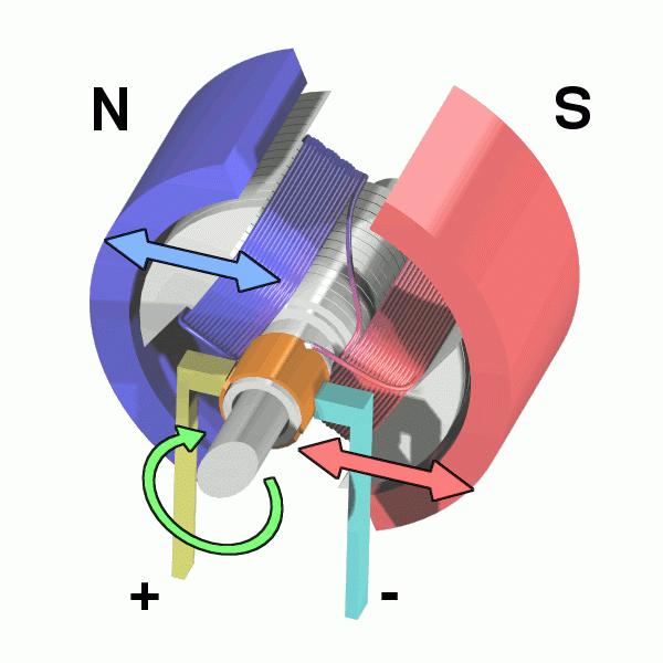
2 Motor or Servo? Motor Faster revolution but less Power Tetrix 12 Volt DC motors have a transmission that slows speed and increases torque Speed controlled by varying voltage (Pulse Width Modulation) Controlled with Arduino Motor Shield REV3 Servo Motor combined with encoder. More powerful, but slower Two types Standard: 180 Degree Rotation Continuous Rotation Three leads: Signal (from pin) 5 Volt Ground
3

4 Tetrix Prizm Microcontroller Left Drive plugged into Motor 1 Right Drive plugged into Motor 2 Sonar plugged into D2 Light plugged into D3 Starter code available at:

5 Tetrix Prizm Components

6 Setup for Prizm, Switch, Battery, and Motor
7 Setup for Prizm, Switch, Battery, and Servo
8 Setup for Prizm, Switch, Battery, and Sensor
9 Key Functions void setup() Must be defined Runs one time Acts like a constructor in Java void loop() Must be defined Runs continuously (In a loop...) Like the act() method in Greenfoot or Gridworld delay (t) Will pause code for t milliseconds
10 Serial Functions Serial.begin(9600) Initiates Serial Communication at 9600 Baud Called in setup() function Serial.println(<string>) Prints string to console Example: Serial.println( Hello ); Serial.println(<number>) Prints number to console
11 Example Code
12 Data Types and Variables
13 Operators
14 Declaring Variables and Arrays Variables: int myage = 14; // Integer float angle = 2*PI; // Float String name = Mr. Michaud ; Arrays: int pins [] = {3, 4, 5, 6}; String gospels [] = { Matthew, Mark, Luke, John };
15 For Loop Repeats section of code while counting up or down with an index variable Example for (int i = 0; i < 10; i++) { } Serial.println(i); Returns:
16 for (int i = 0; i < 10; i++) {} i++ means "i = i + 1" int i means "integer i" for (int i = 0; i < 10; i++) means "For index variable i starting at 0, while i is less than 10, count be 1."
17 Combined For Loop and Array
18 Conditional Statements if statement : Checks if a given statement or expression is true and then executes a section of code if (score > 9) { Serial.println( You Win ); }
19 While Loop Executes a Segment of Code while a Condition is True
20 TETRIX PRIZM Arduino Library Functions Chart Description Function Coding Example Prizm Begin Is called in the Arduino code setup() loop. Initializes the PRIZM controller. Prizm End When called, immediately terminates a program and resets the PRIZM controller. Set Red LED Sets the PRIZM red indicator LED to on or off. Set Green LED Sets the PRIZM green indicator LED to on or off. Set DC Motor Power Sets the power level and direction of a TETRIX DC motor connected to the PRIZM DC motor ports. Power level range is 0 to 100. Direction is set by the sign (+/-) of the power level. Power level 0 = stop in coast mode. Power level 125 = stop in brake mode. Set DC Motor Powers Simultaneously sets the power level and direction of both TETRIX DC motors connected to the PRIZM motor ports. Both PRIZM Motor 1 and Motor 2 channel parameters are set with a single statement. The power level range is 0 to 100. Direction is set by the sign (+/-) of the power level. Power level 0 = stop in coast mode. Power level 125 = stop in brake mode. Set DC Motor Speed Uses velocity PID control to set the constant speed of a TETRIX DC motor with a TETRIX motor encoder connected. The speed parameter range is 0 to 720 degrees per second (DPS). The sign (+/-) of the speed parameter controls direction of rotation. 146 Appendix PrizmBegin(); None PrizmEnd(); None setredled(state); state = integer state = 1 or 0 or state = HIGH or LOW setgreenled(state); state = integer state = 1 or 0 or state = HIGH or LOW setmotorpower(motor#, power); motor# = integer power = integer motor# = 1 or 2 power = -100 to 100 or power = 125 (brake mode) setmotorpowers(power1, power2); power1 = integer power2 = integer power1 = -100 to 100 power2 = -100 to 100 or power1 = 125 (brake mode) power2 = 125 (brake mode) setmotorspeed(motor#, speed); motor# = integer speed = integer motor# = 1 or 2 speed = -720 to 720 PrizmBegin(); Reset and initialize PRIZM controller. PrizmEnd(); Terminate a PRIZM program and reset controller. setredled(high); or setredled(1); Turn red LED on. setredled(low); or setredled(0); Turn red LED off. setgreenled(high); or setgreenled(1); Turn green LED on. setgreenled(low); or setgreenled(0); Turn green LED off. setmotorpower(1, 50); Spin Motor 1 clockwise at 50% power. setmotorpower(2, -50%); Spin Motor 2 counterclockwise at 50% power. setmotorpower(1, 0); Turn off Motor 1 in coast mode. setmotorpower(2, 125); Turn off Motor 2 in brake mode. setmotorpowers(50, 50); Spin Motor 1 and Motor 2 clockwise at 50% power. setmotorpowers(-50, 50); Spin Motor 1 counterclockwise and Motor 2 clockwise at 50% power. setmotorpowers(0, 0); Turn off Motor 1 and Motor 2 in coast mode. setmotorpowers(125, 125); Turn off Motor 1 and Motor 2 in brake mode. setmotorspeed(1, 360); Spin Motor 1 clockwise at a constant speed of 360 DPS. setmotorspeed(1, -360); Spin Motor 1 counterclockwise at a constant speed of 360 DPS.
21 Description Function Coding Example Set DC Motor Speeds Uses velocity PID control to simultaneously set the constant speeds of both TETRIX DC motor channels with TETRIX motor encoders connected. Both PRIZM Motor 1 and Motor 2 channel parameters are set with a single statement. The speed parameter range is 0 to 720 degrees per second (DPS). The sign (+/-) of the speed parameter controls direction of rotation. Set DC Motor Target Implements velocity and positional PID control to set the constant speed and the encoder count target holding position of a TETRIX DC motor with a TETRIX encoder connected. The speed parameter range is 0 to 720 degrees per second (DPS). The encoder count target position is a signed long integer from -2,147,483,648 to 2,147,483,647. Each encoder count = 1/4-degree resolution. Set DC Motor Targets Implements velocity and positional PID control to simultaneously set the constant speeds and the encoder count target holding positions of both TETRIX DC motor channels each with TETRIX encoders connected. Both PRIZM Motor 1 and Motor 2 channel parameters are set with a single statement. The speed parameter range is 0 to 720 degrees per second (DPS). The encoder count target position is a signed long integer from -2,147,483,648 to 2,147,483,647. Each encoder count = 1/4-degree resolution. setmotorspeeds(speed1, speed2); speed1 = integer speed2 = integer speed1 = -720 to 720 speed2 = -720 to 720 setmotortarget(motor#, speed, target); motor# = integer speed = integer target = long motor# = 1 or 2 speed = 0 to 720 target = to setmotortargets(speed1, target1, speed2, target2); speed1 = integer target1 = long speed2 = integer target2 = long speed1 = 0 to 720 target1 = to speed2 = 0 to 720 target2 = to setmotorspeeds(360, 360); Spin Motor 1 and Motor 2 clockwise at a constant speed of 360 DPS. setmotorspeeds(360, -360); Spin Motor 1 clockwise and Motor 2 counterclockwise at a constant speed of 360 DPS. setmotorspeeds(360, -180); Spin Motor 1 clockwise and Motor 2 counterclockwise at a constant speed of 180 DPS. setmotortarget(1, 360, 1440); Spin Motor 1 at a constant speed of 360 DPS until encoder 1 count equals 1,440. When at encoder target count, hold position in a servo-like mode. setmotortarget(2, 180, -1440); Spin Motor 2 at a constant speed of 180 DPS until encoder 2 count equals -1,440 (1 revolution). When at encoder target count, hold position in a servo-like mode. setmotortargets(360, 1440, 360, 1440); Spin Motor 1 and Motor 2 at a constant speed of 360 DPS until each motor encoder count equals 1,440. When a motor reaches its encoder target count, hold position in a servo-like mode. setmotortargets(360, 1440, 180, 2880); Spin Motor 1 at a constant speed of 360 DPS until encoder 1 count equals 1,440. Spin Motor 2 at a constant speed of 180 DPS until encoder 2 equals 2,880. Each motor will hold its position in a servolike mode when it reaches the encoder target. Set Motor Degree Implements velocity and positional PID control to set the constant speed and the degree target holding position of a TETRIX DC motor with a TETRIX encoder connected. The speed parameter range is 0 to 720 degrees per second (DPS). The encoder degrees target position is a signed long integer from -536,870,912 to 536,870,911 with a 1-degree resolution. setmotordegree(motor#, speed, degrees); motor# = integer speed = integer degrees = long motor# = 1 or 2 speed = 0 to 720 degrees = to Note: One encoder count equals 1/4-degree resolution. For example, 1 motor revolution equals 1,440 encoder counts (1,440 / 4 = 360). setmotordegree(1, 180, 360); Spin Motor 1 at a constant speed of 180 DPS until encoder 1 degree count equals 360. When at encoder target degree count, hold position in a servo-like mode. setmotordegree(2, 90, 180); Spin Motor 2 at a constant speed of 90 DPS until encoder 2 degree count equals 180. When at encoder target degree count, hold position in a servo-like mode. Appendix 147
22 Description Function Coding Example Set Motor Degrees Implements velocity and positional PID control to set the constant speeds and the degree target holding positions of both TETRIX DC motor channels with TETRIX encoders connected. Both PRIZM Motor 1 and Motor 2 channel parameters are set with a single statement. The speed parameter range is 0 to 720 degrees per second (DPS). The encoder degree target position is a signed long integer from -536,870,912 to 536,870,911 with a 1-degree resolution. setmotordegrees(speed1, degrees1, speed2, degrees2); speed1 = integer degrees1 = long speed2 = integer degrees2 = long speed1 = 0 to 720 degrees1 = to speed2 = 0 to 720 degrees2 = to setmotordegrees(180, 360, 180, 360); Spin Motor 1 and Motor 2 at a constant speed of 180 DPS until each motor encoder degree count equals 360. When a motor reaches its degree target count, hold position in a servo-like mode. setmotordegrees(360, 720, 90, 360); Spin Motor 1 at a constant speed of 360 DPS until encoder 1 degree count equals 720. Spin Motor 2 at a constant speed of 90 DPS until encoder 2 degree equals 360. Each motor will hold its position in a servo-like mode when it reaches the encoder target. Set Motor Direction Invert Inverts the forward/reverse direction mapping of a DC motor channel. This function is intended to harmonize the forward and reverse directions for motors on opposite sides of a skid-steer robot chassis. Inverting one motor channel can make coding opposite-facing DC motors working in tandem more intuitive. An invert parameter of 1 = invert. An invert parameter of 0 = no invert. The default is no invert. setmotorinvert(motor#, invert); motor# = integer invert = integer motor# = 1 or 2 invert = 0 or 1 setmotorinvert(1, 1); Invert the spin direction mapping of Motor 1. setmotorinvert(2, 1); Invert the spin direction mapping of Motor 2. setmotorinvert(1, 0); Do not invert the spin direction mapping of Motor 1. setmotorinvert(2, 0); Do not invert the spin direction mapping of Motor 2. Note: Non-inverting is the default on PRIZM power-up or reset. Read Motor Busy Status The busy flag can be read to check on the status of a DC motor that is operating in positional PID mode. The motor busy status will return 1 if it is moving toward a positional target (degrees or encoder count). When it has reached its target and is in hold mode, the busy status will return 0. Read DC Motor Current Reads the DC motor current of each TETRIX DC motor attached to PRIZM Motor 1 and Motor 2 ports. The integer value that is returned is motor load current in milliamps. readmotorbusy(motor#); motor# = integer motor# = 1 or 2 Data Type Returned: value = integer readmotorcurrent(motor#); motor# = integer motor# = 1 or 2 Data Type Returned: value = integer readmotorbusy(1); Return the busy status of Motor 1. readmotorbusy(2); Return the busy status of Motor 2. readmotorcurrent(1); Read the motor load current of the PRIZM Motor 1 channel. readmotorcurrent(2); Read the motor load current of the PRIZM Motor 2 channel. Example: 1500 = 1.5 amps 148 Appendix
23 Description Function Coding Example Read Encoder Count Reads the encoder count value. The PRIZM controller uses encoder pulse data to implement PID control of a TETRIX DC motor connected to the motor ports. The PRIZM controller counts the number of pulses produced over a set time period to accurately control velocity and position. Each 1/4 degree equals one pulse, or count, or 1 degree of rotation equals 4 encoder counts. The current count can be read to determine a motor s shaft position. The total count accumulation can range from -2,147,483,648 to 2,147,483,647. A clockwise rotation adds to the count value, while a counterclockwise rotation subtracts from the count value. The encoder values are set to 0 at power-up and reset. Read Encoder Degrees Reads the encoder degree value. The PRIZM controller uses encoder pulse data to implement PID control of a TETRIX DC motor connected to the motor ports. The PRIZM controller counts the number of pulses produced over a set time period to accurately control velocity and position. This function is similar to the encoder count function, but instead of returning the raw encoder count value, it returns the motor shaft position in degrees. The total degree count accumulation can range from -536,870,912 to 536,870,911. A clockwise rotation adds to the count value, while a counterclockwise rotation subtracts from the count value. The encoder values are set to 0 at power-up and reset. Reset Each Encoder Resets the encoder count accumulator to 0. readencodercount(enc#); enc# = integer enc# = 1 or 2 Data Type Returned: value = long readencoderdegrees(enc#); enc# = integer enc# = 1 or 2 Data Type Returned: value = long resetencoder(enc#); enc# = integer readencodercount(1); Read the current count value of encoder 1 (ENC 1 port). readencodercount(2); Read the current count value of encoder 2 (ENC 2 port). readencoderdegrees(1); Read the current degree count value of encoder 1 (ENC 1 port). readencoderdegrees(2); Read the current degree count value of encoder 2 (ENC 2 port). resetencoder(1); Reset the encoder 1 count to 0. resetencoder(2); Reset the encoder 2 count to 0. Reset Both Encoders (1 and 2) Resets the encoder 1 and encoder 2 count accumulators to 0. = 1 or 2 resetencoders(); None resetencoders(); Reset the encoder 1 count to 0 and encoder 2 count to 0. Appendix 149
24 Description Function Coding Example Read Line Sensor Output Reads the digital output of the Line Finder Sensor connected to a PRIZM sensor port. The value read is 0 when reflected light is received (detecting a light-colored surface) and 1 when light is not received (detecting a darkcolored surface, such as a line). Read Ultrasonic Sensor in Centimeters Reads the distance in centimeters of an object placed in front of the Ultrasonic Sensor. The sensor is modulated at 42 khz and has a range of 3 to 400 centimeters. The value read is an integer. Read Ultrasonic Sensor in Inches Reads the distance in inches of an object placed in front of the Ultrasonic Sensor. The sensor is modulated at 42 khz and has a range of 2 to 150 inches. The value read is an integer. Read Battery Pack Voltage Reads the voltage of the TETRIX battery pack powering the PRIZM controller. The value read is an integer. readlinesensor(port#); port# = integer port# (See note in adjacent column.) Data Type Returned: value = integer (0 or 1) readsonicsensorcm(port#); port# = integer port# (See note in adjacent column.) Data Type Returned: value = integer (3 to 400) Min and max might slightly vary. readsonicsensorin(port#); port# = integer port# (See note in adjacent column.) Data Type Returned: value = integer (2 to 150) Min and max might slightly vary. readbatteryvoltage(); None Data Type Returned: value = integer readlinesensor(2); Read the digital value of a Line Finder Sensor on digital sensor port D2. Note: The Line Finder Sensor can be connected to any digital port D2-D5, or analog ports A1-A3 configured as digital input. See technical section on sensor ports for a more detailed explanation of sensor ports and pinouts. readsonicsensorcm(3); Read the distance in centimeters of an object placed in front of the Ultrasonic Sensor connected to digital sensor port D3. Note: The Ultrasonic Sensor can be connected to any digital port D2-D5, or analog ports A1-A3 configured as digital input. See technical section on sensor ports for a more detailed explanation of sensor ports and pinouts. readsonicsensorin(4); Read the distance in inches of an object placed in front of the Ultrasonic Sensor connected to digital sensor port D4. Note: The Ultrasonic Sensor can be connected to any digital port D2-D5, or analog ports A1-A3 configured as digital input. readbatteryvoltage(); Read the voltage of the TETRIX battery pack powering the PRIZM controller. Example: A value of 918 equals 9.18 volts. Read Start Button State Reads the state of the green PRIZM Start button. A returned value of 1 indicates a pressed state. A returned value of 0 indicates a not-pressed state. readstartbutton(); None Data Type Returned: value = integer (0 or 1) readstartbutton(); Read the Start button. A value of 1 means button is pressed. A value of 0 means button is not pressed. 150 Appendix
25 Description Function Coding Example Set Speed of a Servo Motor Sets the speed of a servo motor connected to a PRIZM servo port 1-6. The speed parameter can be 0 to 100%. The servo motor channel parameter can be any number 1 to 6. If not specified, the speed of a servo defaults to 100 (maximum speed). When a servo speed has been set, it will always move at the set speed until changed. Unless we are changing speeds, it will need to be called only once at the beginning of a program. Set Speeds of All Servo Motors Sets the speeds of all six servo channels simultaneously with a single command. All six speeds are in sequential order and can be 0 to 100%. All six servo speeds may be the same or different. Set Position of a Servo Motor Sets the angular position of a servo motor connected to a PRIZM servo motor port 1-6. The position parameter can be any value between 0 and 180 degrees. Any value outside this range is ignored. Not all servos are the same, so be careful when operating a servo motor at the extreme ranges. Listen closely; if a servo is buzzing, it is pressing against its mechanical stop, which might damage the motor. If this happens, limit the range to values slightly greater than 0 and slightly less than 180 to avoid damage to the servo motor. Set Positions of All Servo Motors Sets the angular positions of all six servo motors connected to the PRIZM servo motor ports 1-6. The position parameter can be any value between 0 and 180 degrees. Any value outside this range is ignored. Not all servos are the same, so be careful when operating a servo motor at the extreme ranges. Listen closely; if a servo is buzzing, it is pressing against its mechanical stop, which might damage the motor. If this happens, limit the range to values slightly greater than 0 and slightly less than 180 to avoid damage to the servo motor. setservospeed(servo#, speed); servo# = integer speed = integer servo# = 1 to 6 speed = 0 to 100 setservospeeds(speed1, speed2, speed3, speed4, speed5, speed6); speed1-speed6 = integer speed1-speed6 = 0 to 100 setservoposition(servo#, position); servo# = integer position = integer servo# = 1 to 6 position = 0 to 180 setservopositions(position1, position2, position3, position4, position5, position6); position1-position6 = integer position1-position6 = 0 to 180 setservospeed(1, 25); Set the speed of servo channel 1 to 25%. setservospeed(2, 50); Set the speed of servo channel 2 to 50%. setservospeeds(25, 25, 25, 25, 25, 25); Set the speeds of all six servo channels to 25%. setservospeeds(25, 35, 45, 55, 65, 75); Servo 1 speed = 25% Servo 2 speed = 35% Servo 3 speed = 45% Servo 4 speed = 55% Servo 5 speed = 65% Servo 6 speed = 75% setservoposition(1, 90); Set the angular position of Servo Motor 1 to 90 degrees. setservoposition(2, 130); Set the angular position of Servo Motor 2 to 130 degrees. setservopositions(90, 90, 90, 90, 90, 90); Set the angular positions of all six servo motors connected to PRIZM servo ports 1-6 to 90 degrees. setservopositions(10, 20, 30, 40, 50, 60); Set the angular positions of all six servo motors connected to PRIZM servo ports 1-6. Servo 1 position = 10 degrees Servo 2 position = 20 degrees Servo 3 position = 30 degrees Servo 4 position = 40 degrees Servo 5 position = 50 degrees Servo 6 position = 60 degrees Appendix 151
26 Description Function Coding Example Read a Servo Position Reads the most recent commanded position of a servo motor connected to PRIZM servo ports 1-6. The value returned will be readservoposition(servo#); servo# = integer servo# = 1 to 6 readservoposition(1); Read the most recent commanded position of Servo 1. readservoposition(2); Read the most recent commanded position of Servo 2. Set Continuous Rotation (CR) State Sets the on/off and direction state of a CR servo connected to PRIZM CR1 and CR2 ports. A state parameter of -100 equals spin counterclockwise. A state parameter of 100 equals spin clockwise. A state parameter of 0 is off or stop. CRservo# parameter can be 1 or 2 commanding either CR1 or CR2 servo ports. Data Type Returned: value = integer (0 to 180) setcrservostate(crservo#, state); CRservo# = integer state = integer CRservo# = 1 or 2 state = -100, 0, 100 setcrservostate(1, 100); Spin CR1 servo continuously clockwise. setcrservostate(1, 0); Stop CR1 servo. setcrservostate(1, -100); Spin CR1 servo continuously counterclockwise. 152 Appendix
27 Complete Programming Guide for Tetrix Prizm Arduino
28 Other Arduino References Java Key Vocabulary: ( utsandbolts/index.html) Arduino IDO Reference: Another Good Reference:
29 REV3 Motor Control and Tetrix Left Drive is plugged into MotorA Right Drive is plugged into MotorB Starter Code Available at: Motor Control Speed (Converts PWM signals) Direction (HIGH, LOW) Brake On or Off (HIGH, LOW)
 Red wires are positive (current) Black are negative")
30 Arduino REV3 Motor Controller Motor B (Right) Switch Motor A (Left) Red wires are positive (current) Black are negative (ground)
31 Utility Functions Provided for REV3 Function Name Description Example void motora(int power) void motora(int power, int t) void motorb(int power) Turns on Motor A at power indicated. Range from -255 to 255. Negative numbers are backwards, Positive is forward. Zero means stop Turns on Motor A at power indicated for t microseconds. Stops motor when finished. Range from -255 to 255. Negative numbers are backwards, Positive is forward. Zero means stop. Turns on Motor B at power indicated. Range from -255 to 255. Negative numbers are backwards, Positive is forward. Zero means stop motora(150); motora(150, 1000); // motor A at 150 // power // for 1 second motorb(100); void motorb(int power, int t) Same as motora() except runs motor B motorb(-100, 2000);

32 Single Power Source Setup
33 Two Types of Servos Standard Only rotates within a 180 Degree range Write Value to Servo holds the position Good for Armatures Hands, Arms Holding Devices Continuous Rotation Rotates like a motor all the way around Values written to Servo set speed 0 -> Full Counterclockwise 180 -> Full Clockwise Good for drive systems Wheels, Rollers
34 Servo Commands Servo Library: Must have this line in the beginning of each program #include <Servo.h> To Create Instance of Servo Object: (myservo can be any name) Servo myservo; To Attach a Servo to a Pin: myservo.attach(9); To Start Servo: myservo.write(0);
Computational Crafting with Arduino. Christopher Michaud Marist School ECEP Programs, Georgia Tech
 Computational Crafting with Arduino Christopher Michaud Marist School ECEP Programs, Georgia Tech Introduction What do you want to learn and do today? Goals with Arduino / Computational Crafting Purpose
General Description. The TETRIX MAX Servo Motor Expansion Controller features the following:
 General Description The TETRIX MAX Servo Motor Expansion Controller is a servo motor expansion peripheral designed to allow the addition of multiple servo motors to the PRIZM Robotics Controller. The device
TETRIX Servo Motor Expansion Controller Technical Guide
 TETRIX Servo Motor Expansion Controller Technical Guide 44560 Content advising by Paul Uttley. SolidWorks Composer and KeyShot renderings by Tim Lankford, Brian Eckelberry, and Jason Redd. Desktop publishing
Mechatronics Engineering and Automation Faculty of Engineering, Ain Shams University MCT-151, Spring 2015 Lab-4: Electric Actuators
 Mechatronics Engineering and Automation Faculty of Engineering, Ain Shams University MCT-151, Spring 2015 Lab-4: Electric Actuators Ahmed Okasha, Assistant Lecturer okasha1st@gmail.com Objective Have a
A servo is an electric motor that takes in a pulse width modulated signal that controls direction and speed. A servo has three leads:
 Project 4: Arduino Servos Part 1 Description: A servo is an electric motor that takes in a pulse width modulated signal that controls direction and speed. A servo has three leads: a. Red: Current b. Black:
Arduino and Servo Motor
 Arduino and Servo Motor 1. Basics of the Arduino Board and Arduino a. Arduino is a mini computer that can input and output data using the digital and analog pins b. Arduino Shield: mounts on top of Arduino
Parts List. Robotic Arm segments ¼ inch screws Cable XBEE module or Wifi module
 Robotic Arm 1 Legal Stuff Stensat Group LLC assumes no responsibility and/or liability for the use of the kit and documentation. There is a 90 day warranty for the Sten-Bot kit against component defects.
100UF CAPACITOR POTENTIOMETER SERVO MOTOR MOTOR ARM. MALE HEADER PIN (3 pins) INGREDIENTS
 INGREDIENTS") 05 POTENTIOMETER SERVO MOTOR MOTOR ARM 100UF CAPACITOR MALE HEADER PIN (3 pins) INGREDIENTS 63 MOOD CUE USE A SERVO MOTOR TO MAKE A MECHANICAL GAUGE TO POINT OUT WHAT SORT OF MOOD YOU RE IN THAT DAY Discover:
05 POTENTIOMETER SERVO MOTOR MOTOR ARM 100UF CAPACITOR MALE HEADER PIN (3 pins) INGREDIENTS 63 MOOD CUE USE A SERVO MOTOR TO MAKE A MECHANICAL GAUGE TO POINT OUT WHAT SORT OF MOOD YOU RE IN THAT DAY Discover:
Megamark Arduino Library Documentation
 Megamark Arduino Library Documentation The Choitek Megamark is an advanced full-size multipurpose mobile manipulator robotics platform for students, artists, educators and researchers alike. In our mission
TETRIX PULSE Workshop Guide
 TETRIX PULSE Workshop Guide 44512 1 Who Are We and Why Are We Here? Who is Pitsco? Pitsco s unwavering focus on innovative educational solutions and unparalleled customer service began when the company
J. La Favre Using Arduino with Raspberry Pi February 7, 2018
 As you have already discovered, the Raspberry Pi is a very capable digital device. Nevertheless, it does have some weaknesses. For example, it does not produce a clean pulse width modulation output (unless
Coding with Arduino to operate the prosthetic arm
 Setup Board Install FTDI Drivers This is so that your RedBoard will be able to communicate with your computer. If you have Windows 8 or above you might already have the drivers. 1. Download the FTDI driver
Setup Download the Arduino library (link) for Processing and the Lab 12 sketches (link).
 for Processing and the Lab 12 sketches (link).") Lab 12 Connecting Processing and Arduino Overview In the previous lab we have examined how to connect various sensors to the Arduino using Scratch. While Scratch enables us to make simple Arduino programs,
Lab 12 Connecting Processing and Arduino Overview In the previous lab we have examined how to connect various sensors to the Arduino using Scratch. While Scratch enables us to make simple Arduino programs,
CONSTRUCTION GUIDE Robotic Arm. Robobox. Level II
 CONSTRUCTION GUIDE Robotic Arm Robobox Level II Robotic Arm This month s robot is a robotic arm with two degrees of freedom that will teach you how to use motors. You will then be able to move the arm
1. Controlling the DC Motors
 E11: Autonomous Vehicles Lab 5: Motors and Sensors By this point, you should have an assembled robot and Mudduino to power it. Let s get things moving! In this lab, you will write code to test your motors
GE423 Laboratory Assignment 6 Robot Sensors and Wall-Following
 GE423 Laboratory Assignment 6 Robot Sensors and Wall-Following Goals for this Lab Assignment: 1. Learn about the sensors available on the robot for environment sensing. 2. Learn about classical wall-following
B RoboClaw 2 Channel 30A Motor Controller Data Sheet
 B0098 - RoboClaw 2 Channel 30A Motor Controller (c) 2010 BasicMicro. All Rights Reserved. Feature Overview: 2 Channel at 30Amp, Peak 60Amp Battery Elimination Circuit (BEC) Switching Mode BEC Hobby RC
In this activity, you will program the BASIC Stamp to control the rotation of each of the Parallax pre-modified servos on the Boe-Bot.
 Week 3 - How servos work Testing the Servos Individually In this activity, you will program the BASIC Stamp to control the rotation of each of the Parallax pre-modified servos on the Boe-Bot. How Servos
Introduction: Components used:
 Introduction: As, this robotic arm is automatic in a way that it can decides where to move and when to move, therefore it works in a closed loop system where sensor detects if there is any object in a
2.017 DESIGN OF ELECTROMECHANICAL ROBOTIC SYSTEMS Fall 2009 Lab 4: Motor Control. October 5, 2009 Dr. Harrison H. Chin
 2.017 DESIGN OF ELECTROMECHANICAL ROBOTIC SYSTEMS Fall 2009 Lab 4: Motor Control October 5, 2009 Dr. Harrison H. Chin Formal Labs 1. Microcontrollers Introduction to microcontrollers Arduino microcontroller
Programming a Servo. Servo. Red Wire. Black Wire. White Wire
 Programming a Servo Learn to connect wires and write code to program a Servo motor. If you have gone through the LED Circuit and LED Blink exercises, you are ready to move on to programming a Servo. A
MicroManager. Velocity Mode PID Dancer/Loadcell Control. Instruction Manual MM3000-PID
 MicroManager Velocity Mode PID Dancer/Loadcell Control Instruction Manual MM3000-PID Table of Contents 1. General Description... 5 2. Specifications... 5 2.1 Electrical... 5 2.2 Physical... 6 3. Installation...
Roborodentia Robot: Tektronix. Sean Yap Advisor: John Seng California Polytechnic State University, San Luis Obispo June 8th, 2016
 Roborodentia Robot: Tektronix Sean Yap Advisor: John Seng California Polytechnic State University, San Luis Obispo June 8th, 2016 Table of Contents Introduction... 2 Problem Statement... 2 Software...
Sten-Bot Robot Kit Stensat Group LLC, Copyright 2013
 Sten-Bot Robot Kit Stensat Group LLC, Copyright 2013 Legal Stuff Stensat Group LLC assumes no responsibility and/or liability for the use of the kit and documentation. There is a 90 day warranty for the
LED + Servo 2 devices, 1 Arduino
 LED + Servo 2 devices, 1 Arduino Learn to connect and write code to control both a Servo and an LED at the same time. Many students who come through the lab ask if they can use both an LED and a Servo
Lesson4 Obstacle avoidance car
 Lesson4 Obstacle avoidance car 1 Points of this section The joy of learning, is not just know how to control your car, but also know how to protect your car. So, make you car far away from collision. Learning
Figure 1. Digilent DC Motor
 Laboratory 9 - Usage of DC- and servo-motors The current laboratory describes the usage of DC and servomotors 1. DC motors Figure 1. Digilent DC Motor Classical DC motors are converting electrical energy
Introduction to the VEX Robotics Platform and ROBOTC Software
 Introduction to the VEX Robotics Platform and ROBOTC Software Computer Integrated Manufacturing 2013 Project Lead The Way, Inc. VEX Robotics Platform: Testbed for Learning Programming VEX Structure Subsystem
Jaguar Motor Controller (Stellaris Brushed DC Motor Control Module with CAN)
") Jaguar Motor Controller (Stellaris Brushed DC Motor Control Module with CAN) 217-3367 Ordering Information Product Number Description 217-3367 Stellaris Brushed DC Motor Control Module with CAN (217-3367)
Jaguar Motor Controller (Stellaris Brushed DC Motor Control Module with CAN) 217-3367 Ordering Information Product Number Description 217-3367 Stellaris Brushed DC Motor Control Module with CAN (217-3367)
Experiment 4.B. Position Control. ECEN 2270 Electronics Design Laboratory 1
 Experiment 4.B Position Control Electronics Design Laboratory 1 Procedures 4.B.1 4.B.2 4.B.3 4.B.4 Read Encoder with Arduino Position Control by Counting Encoder Pulses Demo Setup Extra Credit Electronics
MicroManager. Torque Mode CTCW/Loadcell Control. Instruction Manual MM3000-CTCW
 MicroManager Torque Mode CTCW/Loadcell Control Instruction Manual MM3000-CTCW Table of Contents 1. General Description... 5 2. Specifications... 5 2.1 Electrical... 5 2.2 Physical... 6 3. Installation...
Tech Note #3: Setting up a Servo Axis For Closed Loop Position Control Application note by Tim McIntosh September 10, 2001
 Tech Note #3: Setting up a Servo Axis For Closed Loop Position Control Application note by Tim McIntosh September 10, 2001 Abstract: In this Tech Note a procedure for setting up a servo axis for closed
Chapter 6: Sensors and Control
 Chapter 6: Sensors and Control One of the integral parts of a robot that transforms it from a set of motors to a machine that can react to its surroundings are sensors. Sensors are the link in between
FlareBot. Analysis of an Autonomous Robot. By: Sanat S. Sahasrabudhe Advisor: Professor John Seng
 FlareBot Analysis of an Autonomous Robot By: Sanat S. Sahasrabudhe Advisor: Professor John Seng Presented to: Computer Engineering, California Polytechnic State University June 2013 Introduction: In the
Robotic Arm Assembly Instructions
 Robotic Arm Assembly Instructions Last Revised: 11 January 2017 Part A: First follow the instructions: http://www.robotshop.com/media/files/zip2/rbmea-02_-_documentation_1.zip While assembling the servos:
Learning Objectives. References 10/26/11. Using servos with an Arduino. EAS 199A Fall 2011
 Using servos with an Arduino EAS 199A Fall 2011 Learning Objectives Be able to identify characteristics that distinguish a servo and a DC motor Be able to describe the difference a conventional servo and
Lab 06: Ohm s Law and Servo Motor Control
 CS281: Computer Systems Lab 06: Ohm s Law and Servo Motor Control The main purpose of this lab is to build a servo motor control circuit. As with prior labs, there will be some exploratory sections designed
Using Servos with an Arduino
 Using Servos with an Arduino ME 120 Mechanical and Materials Engineering Portland State University http://web.cecs.pdx.edu/~me120 Learning Objectives Be able to identify characteristics that distinguish
Lab 5: Inverted Pendulum PID Control
 Lab 5: Inverted Pendulum PID Control In this lab we will be learning about PID (Proportional Integral Derivative) control and using it to keep an inverted pendulum system upright. We chose an inverted
Arduino Advanced Projects
 Arduino Advanced Projects Created as a companion manual to the Toronto Public Library Arduino Kits. Arduino Advanced Projects Copyright 2017 Toronto Public Library. All rights reserved. Published by the
Project 27 Joystick Servo Control
 Project 27 Joystick Servo Control For another simple project, let s use a joystick to control the two servos. You ll arrange the servos in such a way that you get a pan-tilt head, such as is used for CCTV
Lecture 6. Interfacing Digital and Analog Devices to Arduino. Intro to Arduino
 Lecture 6 Interfacing Digital and Analog Devices to Arduino. Intro to Arduino PWR IN USB (to Computer) RESET SCL\SDA (I2C Bus) POWER 5V / 3.3V / GND Analog INPUTS Digital I\O PWM(3, 5, 6, 9, 10, 11) Components
TETRIX PRIZM Workshop Guide
 TETRIX PRIZM Workshop Guide 43527 1 Who Are We and Why Are We Here? Who is Pitsco? Pitsco s unwavering focus on innovative educational solutions and unparalleled customer service began when the company
TWEAK THE ARDUINO LOGO
 TWEAK THE ARDUINO LOGO Using serial communication, you'll use your Arduino to control a program on your computer Discover : serial communication with a computer program, Processing Time : 45 minutes Level
Brushed DC Motor Microcontroller PWM Speed Control with Optical Encoder and H-Bridge
 Brushed DC Motor Microcontroller PWM Speed Control with Optical Encoder and H-Bridge L298 Full H-Bridge HEF4071B OR Gate Brushed DC Motor with Optical Encoder & Load Inertia Flyback Diodes Arduino Microcontroller
FABO ACADEMY X ELECTRONIC DESIGN
 ELECTRONIC DESIGN MAKE A DEVICE WITH INPUT & OUTPUT The Shanghaino can be programmed to use many input and output devices (a motor, a light sensor, etc) uploading an instruction code (a program) to it
Brushed DC Motor Control. Module with CAN (MDL-BDC24)
") Stellaris Brushed DC Motor Control Module with CAN (MDL-BDC24) Ordering Information Product No. MDL-BDC24 RDK-BDC24 Description Stellaris Brushed DC Motor Control Module with CAN (MDL-BDC24) for Single-Unit
Stellaris Brushed DC Motor Control Module with CAN (MDL-BDC24) Ordering Information Product No. MDL-BDC24 RDK-BDC24 Description Stellaris Brushed DC Motor Control Module with CAN (MDL-BDC24) for Single-Unit
Deriving Consistency from LEGOs
 Deriving Consistency from LEGOs What we have learned in 6 years of FLL and 7 years of Lego Robotics by Austin and Travis Schuh 1 2006 Austin and Travis Schuh, all rights reserved Objectives Basic Building
Marine Debris Cleaner Phase 1 Navigation
 Southeastern Louisiana University Marine Debris Cleaner Phase 1 Navigation Submitted as partial fulfillment for the senior design project By Ryan Fabre & Brock Dickinson ET 494 Advisor: Dr. Ahmad Fayed
Introduction to the EXPANSION HUB
 Introduction to the EXPANSION HUB REV ROBOTICS - EXPANSION HUB revrobotics.com ANOTHER CONTROLLER CHOICE MODERN ROBOTICS REV ROBOTICS The Expansion hub does not replace the Modern Robotics System. It is
Rochester Institute of Technology Real Time and Embedded Systems: Project 2a
 Rochester Institute of Technology Real Time and Embedded Systems: Project 2a Overview: Design and implement a STM32 Discovery board program exhibiting multitasking characteristics in simultaneously controlling
Motors and Servos Part 2: DC Motors
 Motors and Servos Part 2: DC Motors Back to Motors After a brief excursion into serial communication last week, we are returning to DC motors this week. As you recall, we have already worked with servos
Robotic Navigation Distance Control Platform
 Robotic Navigation Distance Control Platform System Block Diagram Student: Scott Sendra Project Advisors: Dr. Schertz Dr. Malinowski Date: November 18, 2003 Objective The objective of the Robotic Navigation
the Board of Education
 the Board of Education Voltage regulator electrical power (V dd, V in, V ss ) breadboard (for building circuits) power jack digital input / output pins 0 to 15 reset button Three-position switch 0 = OFF
Date Issued: 12/13/2016 iarmc.06: Draft 6. TEAM 1 - iarm CONTROLLER FUNCTIONAL REQUIREMENTS
 Date Issued: 12/13/2016 iarmc.06: Draft 6 TEAM 1 - iarm CONTROLLER FUNCTIONAL REQUIREMENTS 1 Purpose This document presents the functional requirements for an accompanying controller to maneuver the Intelligent
VEX Robotics Platform and ROBOTC Software. Introduction
 VEX Robotics Platform and ROBOTC Software Introduction VEX Robotics Platform: Testbed for Learning Programming VEX Structure Subsystem VEX Structure Subsystem forms the base of every robot Contains square
Feed-back loop. open-loop. closed-loop
 Servos AJLONTECH Overview Servo motors are used for angular positioning, such as in radio control airplanes. They typically have a movement range of 180 deg but can go up to 210 deg. The output shaft of
Arduino Digital Out_QUICK RECAP
 Arduino Digital Out_QUICK RECAP BLINK File> Examples>Digital>Blink int ledpin = 13; // LED connected to digital pin 13 // The setup() method runs once, when the sketch starts void setup() // initialize
L E C T U R E R, E L E C T R I C A L A N D M I C R O E L E C T R O N I C E N G I N E E R I N G
 P R O F. S L A C K L E C T U R E R, E L E C T R I C A L A N D M I C R O E L E C T R O N I C E N G I N E E R I N G G B S E E E @ R I T. E D U B L D I N G 9, O F F I C E 0 9-3 1 8 9 ( 5 8 5 ) 4 7 5-5 1 0
Introduction to the ME2110 Kit. Controller Box Electro Mechanical Actuators & Sensors Pneumatics
 Introduction to the ME2110 Kit Controller Box Electro Mechanical Actuators & Sensors Pneumatics Features of the Controller Box BASIC Stamp II-SX microcontroller Interfaces with various external devices
Tarocco Closed Loop Motor Controller
 Contents Safety Information... 3 Overview... 4 Features... 4 SoC for Closed Loop Control... 4 Gate Driver... 5 MOSFETs in H Bridge Configuration... 5 Device Characteristics... 6 Installation... 7 Motor
EE 314 Spring 2003 Microprocessor Systems
 EE 314 Spring 2003 Microprocessor Systems Laboratory Project #9 Closed Loop Control Overview and Introduction This project will bring together several pieces of software and draw on knowledge gained in
SRVODRV REV7 INSTALLATION NOTES
 SRVODRV-8020 -REV7 INSTALLATION NOTES Thank you for purchasing the SRVODRV -8020 drive. The SRVODRV -8020 DC servo drive is warranted to be free of manufacturing defects for 1 year from the date of purchase.
ABCs of Arduino. Kurt Turchan -
 ABCs of Arduino Kurt Turchan - kurt@trailpeak.com Bio: Kurt is a web designer (java/php/ui-jquery), project manager, instructor (PHP/HTML/...), and arduino enthusiast, Kurt is founder of www.trailpeak.com
Mercury technical manual
 v.1 Mercury technical manual September 2017 1 Mercury technical manual v.1 Mercury technical manual 1. Introduction 2. Connection details 2.1 Pin assignments 2.2 Connecting multiple units 2.3 Mercury Link
Variateur analogique courant continu série AZ et AZB
 Variateur analogique courant continu série AZ et AZB AZ Analog Drives for servo systems - AMC Advanced Motion Control www.rosier.fr 07/11/2011 page(s) 1-7 Products and System Requirements / Analog PWM
CURIE Academy, Summer 2014 Lab 2: Computer Engineering Software Perspective Sign-Off Sheet
 Lab : Computer Engineering Software Perspective Sign-Off Sheet NAME: NAME: DATE: Sign-Off Milestone TA Initials Part 1.A Part 1.B Part.A Part.B Part.C Part 3.A Part 3.B Part 3.C Test Simple Addition Program
4WD Mobile Platform SKU:ROB0022
 4WD Mobile Platform SKU:ROB0022 Contents [hide] 1 Function Introduction 1.1 STEP1: Assemble Robot 1.2 STEP2: Debug Motor 1.3 STEP3:Install Upper Plate 1.4 STEP4: Debug Ultrasonic Sensor and Servo 1.5 STEP5:
Operating Mode: Serial; (PWM) passive control mode; Autonomous Mode; On/OFF Mode
 passive control mode; Autonomous Mode; On/OFF Mode") RB-Dfr-11 DFRobot URM V3.2 Ultrasonic Sensor URM37 V3.2 Ultrasonic Sensor uses an industrial level AVR processor as the main processing unit. It comes with a temperature correction which is very unique
RB-Dfr-11 DFRobot URM V3.2 Ultrasonic Sensor URM37 V3.2 Ultrasonic Sensor uses an industrial level AVR processor as the main processing unit. It comes with a temperature correction which is very unique
MICROCONTROLLERS Stepper motor control with Sequential Logic Circuits
 PH-315 MICROCONTROLLERS Stepper motor control with Sequential Logic Circuits Portland State University Summary Four sequential digital waveforms are used to control a stepper motor. The main objective
Assignments from last week
 Assignments from last week Review LED flasher kits Review protoshields Need more soldering practice (see below)? http://www.allelectronics.com/make-a-store/category/305/kits/1.html http://www.mpja.com/departments.asp?dept=61
Design with Microprocessors Year III Computer Science 1-st Semester
 Design with Microprocessors Year III Computer Science 1-st Semester Lecture 9: Microcontroller based applications: usage of sensors and actuators (motors) DC motor control Diligent MT motor/gearbox 1/19
StenBOT Robot Kit. Stensat Group LLC, Copyright 2018
 StenBOT Robot Kit 1 Stensat Group LLC, Copyright 2018 Legal Stuff Stensat Group LLC assumes no responsibility and/or liability for the use of the kit and documentation. There is a 90 day warranty for the
The Allen-Bradley Servo Interface Module (Cat. No SF1) when used with the Micro Controller (Cat. No UC1) can control single axis
 when used with the Micro Controller (Cat. No UC1) can control single axis") Table of Contents The Allen-Bradley Servo Interface Module (Cat. No. 1771-SF1) when used with the Micro Controller (Cat. No. 1771-UC1) can control single axis positioning systems such as found in machine
Table of Contents The Allen-Bradley Servo Interface Module (Cat. No. 1771-SF1) when used with the Micro Controller (Cat. No. 1771-UC1) can control single axis positioning systems such as found in machine
Quantizer step: volts Input Voltage [V]
![Quantizer step: volts Input Voltage [V]](/thumbs/96/126541381.jpg "Quantizer step: volts Input Voltage [V]") EE 101 Fall 2008 Date: Lab Section # Lab #8 Name: A/D Converter and ECEbot Power Abstract Partner: Autonomous robots need to have a means to sense the world around them. For example, the bumper switches
EE 101 Fall 2008 Date: Lab Section # Lab #8 Name: A/D Converter and ECEbot Power Abstract Partner: Autonomous robots need to have a means to sense the world around them. For example, the bumper switches
HAW-Arduino. Sensors and Arduino F. Schubert HAW - Arduino 1
 HAW-Arduino Sensors and Arduino 14.10.2010 F. Schubert HAW - Arduino 1 Content of the USB-Stick PDF-File of this script Arduino-software Source-codes Helpful links 14.10.2010 HAW - Arduino 2 Report for
Teaching Children Proportional Control using ROBOLAB 2.9. By Dr C S Soh
 Teaching Children Proportional Control using ROBOLAB 2.9 By Dr C S Soh robodoc@fifth-r.com Objective Using ROBOLAB 2.9, children can experiment with proportional control the same way as undergraduates
Data Sheet. AEDB-9340 Series 1250/2500 CPR Commutation Encoder Modules with Codewheel. Features. Description. Applications
 AEDB-9340 Series 1250/2500 CPR Commutation Encoder Modules with Codewheel Data Sheet Description The AEDB-9340 optical encoder series are six-channel optical incremental encoder modules with codewheel.
Advanced Mechatronics 1 st Mini Project. Remote Control Car. Jose Antonio De Gracia Gómez, Amartya Barua March, 25 th 2014
 Advanced Mechatronics 1 st Mini Project Remote Control Car Jose Antonio De Gracia Gómez, Amartya Barua March, 25 th 2014 Remote Control Car Manual Control with the remote and direction buttons Automatic
I.1 Smart Machines. Unit Overview:
 I Smart Machines I.1 Smart Machines Unit Overview: This unit introduces students to Sensors and Programming with VEX IQ. VEX IQ Sensors allow for autonomous and hybrid control of VEX IQ robots and other
Programming 2 Servos. Learn to connect and write code to control two servos.
 Programming 2 Servos Learn to connect and write code to control two servos. Many students who visit the lab and learn how to use a Servo want to use 2 Servos in their project rather than just 1. This lesson
CONSTRUCTION GUIDE Light Robot. Robobox. Level VI
 CONSTRUCTION GUIDE Light Robot Robobox Level VI The Light In this box dedicated to light we will discover, through 3 projects, how light can be used in our robots. First we will see how to insert headlights
Attribution Thank you to Arduino and SparkFun for open source access to reference materials.
 Attribution Thank you to Arduino and SparkFun for open source access to reference materials. Contents Parts Reference... 1 Installing Arduino... 7 Unit 1: LEDs, Resistors, & Buttons... 7 1.1 Blink (Hello
Jaguar speed controllers
 Jaguar speed controllers When used with CAN control, Jaguars are smart speed controllers. You can simply send a command to the Jaguar such as a position setpoint and it will use attached sensors to move
Built-in soft-start feature. Up-Slope and Down-Slope. Power-Up safe start feature. Motor will only start if pulse of 1.5ms is detected.
 Thank You for purchasing our TRI-Mode programmable DC Motor Controller. Our DC Motor Controller is the most flexible controller you will find. It is user-programmable and covers most applications. This
ME 2110 Controller Box Manual. Version 2.3
 ME 2110 Controller Box Manual Version 2.3 I. Introduction to the ME 2110 Controller Box A. The Controller Box B. The Programming Editor & Writing PBASIC Programs C. Debugging Controller Box Problems II.
DC motor control using arduino
 DC motor control using arduino 1) Introduction: First we need to differentiate between DC motor and DC generator and where we can use it in this experiment. What is the main different between the DC-motor,
Experiment 1: Robot Moves in 3ft squared makes sound and
 Experiment 1: Robot Moves in 3ft squared makes sound and turns on an LED at each turn then stop where it started. Edited: 9-7-2015 Purpose: Press a button, make a sound and wait 3 seconds before starting
Electronics Merit Badge Kit Theory of Operation
 Electronics Merit Badge Kit Theory of Operation This is an explanation of how the merit badge kit functions. There are several topics worthy of discussion. These are: 1. LED operation. 2. Resistor function
ECE 477 Digital Systems Senior Design Project Rev 8/09. Homework 5: Theory of Operation and Hardware Design Narrative
 ECE 477 Digital Systems Senior Design Project Rev 8/09 Homework 5: Theory of Operation and Hardware Design Narrative Team Code Name: _ATV Group No. 3 Team Member Completing This Homework: Sebastian Hening
Boe-Bot robot manual
 Tallinn University of Technology Department of Computer Engineering Chair of Digital Systems Design Boe-Bot robot manual Priit Ruberg Erko Peterson Keijo Lass Tallinn 2016 Contents 1 Robot hardware description...3
Roborodentia Final Report
 California Polytechnic State University, SLO College of Engineering Computer Engineering Program Roborodentia Final Report Submitted by: Zeph Nord, Mitchell Myjak, Trevor Gesell June 2018 Faculty Advisor:
Disclaimer. Arduino Hands-On 2 CS5968 / ART4455 9/1/10. ! Many of these slides are mine. ! But, some are stolen from various places on the web
 Arduino Hands-On 2 CS5968 / ART4455 Disclaimer! Many of these slides are mine! But, some are stolen from various places on the web! todbot.com Bionic Arduino and Spooky Arduino class notes from Tod E.Kurt!
Chapter 7: The motors of the robot
 Chapter 7: The motors of the robot Learn about different types of motors Learn to control different kinds of motors using open-loop and closedloop control Learn to use motors in robot building 7.1 Introduction
High Speed Continuous Rotation Servo (# )
") Web Site: www.parallax.com Forums: forums.parallax.com Sales: sales@parallax.com Technical: support@parallax.com Office: (916) 624-8333 Fax: (916) 624-8003 Sales: (888) 512-1024 Tech Support: (888) 997-8267
Web Site: www.parallax.com Forums: forums.parallax.com Sales: sales@parallax.com Technical: support@parallax.com Office: (916) 624-8333 Fax: (916) 624-8003 Sales: (888) 512-1024 Tech Support: (888) 997-8267
BEYOND TOYS. Wireless sensor extension pack. Tom Frissen s
 LEGO BEYOND TOYS Wireless sensor extension pack Tom Frissen s040915 t.e.l.n.frissen@student.tue.nl December 2008 Faculty of Industrial Design Eindhoven University of Technology 1 2 TABLE OF CONTENT CLASS
The Robot Builder's Shield for Arduino
 The Robot Builder's Shield for Arduino by Ro-Bot-X Designs Introduction. The Robot Builder's Shield for Arduino was especially designed to make building robots with Arduino easy. The built in dual motors
B Robo Claw 2 Channel 25A Motor Controller Data Sheet
 B0098 - Robo Claw 2 Channel 25A Motor Controller Feature Overview: 2 Channel at 25A, Peak 30A Hobby RC Radio Compatible Serial Mode TTL Input Analog Mode 2 Channel Quadrature Decoding Thermal Protection
EE-110 Introduction to Engineering & Laboratory Experience Saeid Rahimi, Ph.D. Labs Introduction to Arduino
 EE-110 Introduction to Engineering & Laboratory Experience Saeid Rahimi, Ph.D. Labs 10-11 Introduction to Arduino In this lab we will introduce the idea of using a microcontroller as a tool for controlling
URM37 V3.2 Ultrasonic Sensor (SKU:SEN0001)
") URM37 V3.2 Ultrasonic Sensor (SKU:SEN0001) From Robot Wiki Contents 1 Introduction 2 Specification 2.1 Compare with other ultrasonic sensor 3 Hardware requierments 4 Tools used 5 Software 6 Working Mode
URM37 V3.2 Ultrasonic Sensor (SKU:SEN0001) From Robot Wiki Contents 1 Introduction 2 Specification 2.1 Compare with other ultrasonic sensor 3 Hardware requierments 4 Tools used 5 Software 6 Working Mode