Design with Microprocessors Year III Computer Science 1-st Semester
|
|
|
- Warren Pierce Jacobs
- 5 years ago
- Views:
Transcription
1 Design with Microprocessors Year III Computer Science 1-st Semester Lecture 9: Microcontroller based applications: usage of sensors and actuators (motors)
 (quadrature encoder) Motor speed can be determined by the frequency and motor rotation direction can be determined by the phase relationship of the two")
2 DC motor control Diligent MT motor/gearbox 1/19 or 1/53 ratio gearbox Variable speed (value of the average voltage applied) Direction control (voltage polarity) Speed and direction signals (SA, SB) (quadrature encoder) Motor speed can be determined by the frequency and motor rotation direction can be determined by the phase relationship of the two signals.
 EN = 0 (current flows through the H bridge) DIR rotation direction Motor speed")

3 DC motor control Digilent Pmod HB5TM 2A H-Bridge Module (HB5) J3 - motor power (up to 12 V) EN = 0 (current flows through the H bridge) DIR rotation direction Motor speed is controlled by pulse width modulating the EN pin The direction of the motor should not be reversed while the Enable pin is active. This could damage the bridge transistors.
4 H bridge functioning DC motor control
5 DC motor control Pulse Width Modulation and Motor Speed Control In an analog circuit, motor speed is controlled by varying the input voltage to a circuit. In a digital circuit, there are only two ways to control a motor digitally: use a variable resistance circuit to control the motor voltage (expensive, complicated, and wastes much energy in the form of heat) pulse the power to the motor by pulse width modulation (PWM). While voltage is being applied, the motor is driven by the changing magnetic forces. When voltage is stopped, momentum causes the motor to continue spinning a while. At a high enough frequency, this process of powering and coasting enables the motor to achieve a smooth rotation that can easily be controlled through digital logic.
6 PWM driving issues DC motor control PWM has two important effects on DC motors: Inertial resistance is overcome more easily at startup because short bursts of maximum voltage achieve a greater degree of torque than the equivalent DC voltage. Higher level of heat generation inside the motor. If a pulsed motor is used for an extended time, heat dissipation systems may be needed to prevent damage to the motor. Because of these effects, PWM is best used in high-torque infrequent-use applications such as airplane flap servos and robotics. PWM circuits can also create radio frequency interference (RFI) that can be minimized by locating motors near the controller and by using short wires. Line noise created by continually powering up the motor may also need to be filtered to prevent interference with the rest of the circuits. Placing small ceramic capacitors directly across the motor terminals and between the motor terminals and the motor case can be used to filter RFI emissions from the motor.


7 Robotic starter kit (RSK) CerebotII_RSK_StartupDesign:
 The phototransistor responds by varying the")

8 Sensors Fairchild QRB IR Sensor Detects surface reflectivity IR LED + IR phototransistor (same frequency) The phototransistor responds by varying the collector current depending on the incident reflected light The phototransistor response depends on the surface reflectivity and distance between the sensor and the surface

9 Sensors PMod LS1 IR sensors interface To use with IR sensors (up to 4) Analog response of each sensor compared with a reference voltage digital output Reference voltage is adjustable (IR sensor sensibility setting)
 254 in ( 645 cm) with 1-inch resolution. For objects from 0.. 6in range as 6-inches. ADC V 1024 V IN REF 2.56mV d[ cm] 1024 2.")
10 LV-MaxSonar -EZ0 High Performance Sonar Range Finder (see C6) Sonar range finder AN Outputs analog voltage with a scaling factor of (Vcc/512) per inch. A supply voltage of 3.3V yields ~6.4mV/in 2.56 mv/cm Sonar range: 6-in (15 cm) 254 in ( 645 cm) with 1-inch resolution. For objects from 0.. 6in range as 6-inches. ADC V 1024 V IN REF 2.56mV d[ cm] [ V ] d[ cm] ADC_Init: ldi r16, 0b ; Vref=2,56 V internal, ADLAR=0 (Data Shift right), ADC3 single ended out ADMUX, r16 ldi r16, 0b ; Activate ADC, max. speed out ADCSRA, r16 ret ADC_read: in r20, ADCL //ADC access to data registers is blocked in r21, ADCH //ADC access to the ADCH and ADCL Registers is re-enabled // r21:r20 = d[cm] (in r20 range = 15 cm. 256 cm) ret
 Heading direction Cerebot II US sensor Pmod BTN Pmod Hb5 Mt")
11 Features: Move Forward / Left / Right with adjustable speed Autonomous car Detect and follow a freeform black line on a white background Detect objects on the path and adjust speed accordingly or even stop the vehicle IR Sensors Pmod LS1 Mt motor Pmod Hb5 Lane (path) Heading direction Cerebot II US sensor Pmod BTN Pmod Hb5 Mt motor
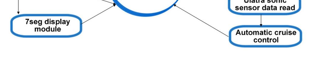
12 Autonomous car
13 Autonomous car Detailed flowchart description: The application entry point at address 0x0000 determines a jump to the initialization module which sets up all the required resources After setup is complete, execution enters the infinite main loop The control from the main loop is taken away by interrupt requests generated by the two timers which have been configured in the initialization step When Timer1 overflow occurs, an interrupt request is generated and the Timer1 Overflow ISR is called. This routine calls in order the following procedures : IR sensor read, Lanekeep, Ultra sonic sensor read, Automatic cruise control After all these procedures have been called control is returned to the main procedure/loop Timer0 will generate both compare match and overflow interrupts which are responsible for pulse width modulation (global speed variation) of the motors Also Timer0 overflow procedure calls the 7segment display procedure which is responsible for controlling the two digit seven segment Pmod which displays the read data (US sensor value)


14 Autonomous car
 2 ms maximum right 180 deg) PWM frequency (pulse period): 30 60 Hz GWS Servo Kit : https://digilentinc.com/products/detail.cfm?")
15 Servo motor control PWM control: pulse width rotation amplitude 1 ms maximum left (0 deg.) 1.5 ms neutral position (90 deg) 2 ms maximum right 180 deg) PWM frequency (pulse period): Hz GWS Servo Kit : Provides 0.23 second/60 degree rotation with 47 oz-in of Torque at 4.8V Continuous rotation servo (feedback sensor disabled) low speed / high torque continuous rotation motor

 Signal VS")
16 Servo and Cerebot Servo motor control 8x3 signals for servo control: GND, VS, Signal Signal bits are common with JH (PORTF 0 7 and ADC) Signal VS Gnd
17 Servo library supports: Arduino Servo library up to 12 motors on most Arduino boards 48 motors on the Arduino Mega. the use of the library disables analogwrite() (PWM) functionality on pins 9 and 10, whether or not there is a Servo on those pins (except Mega). on Mega, up to 12 servos can be used without interfering with PWM functionality; use of 12 to 23 motors will disable PWM on pins 11 and 12. Servo connection (3 wire): power, ground, and signal. The power wire, 5V pin on the Arduino board. The ground wire (black or brown) ground pin on the Arduino board. The signal pin (yellow, orange or white) and should be connected to a digital pin on the Arduino board. Note: servos draw considerable power! To drive >2 servos: power them from a separate supply (i.e. not the +5V pin on your Arduino). Be sure to connect the grounds of the Arduino and external power supply together.
18 Servo library methods: Arduino Servo library servo.attach(pin) / servo.attach(pin, min, max) attach the Servo variable to a pin servo: a variable of type Servo pin: the number of the pin that the servo is attached to min (optional): the pulse width, in microseconds, corresponding to the minimum (0-degree) angle on the servo (defaults to 544) max (optional): the pulse width, in microseconds, corresponding to the maximum (180-degree) angle on the servo (defaults to 2400) servo.detach() - detach the Servo variable from its pin. boolean val servo.attached() - check whether the Servo variable is attached to a pin. Returns val = true or false servo.write(angle) - writes a value ( ) to the servo, controlling the shaft accordingly: standard servo set the angle of the shaft [deg] moving it to that orientation. continuous rotation servo set the speed of the servo (0: full speed in one direction; 180: full speed in the other; 90: no movement) int val servo.read() - read the current angle of the servo (the value passed to the last call to write()). Val - angle of the servo, from 0 to 180 degrees.
 { myservo.")
19 Arduino Servo library Example: Sweeps the shaft of a RC servo motor back and forth across 180 degrees ( #include <Servo.h> Servo myservo; // create servo object to control a servo // a maximum of eight servo objects can be created int pos = 0; // variable to store the servo position void setup() { myservo.attach(9); // attaches the servo on pin 9 to the servo object } void loop() { for(pos = 0; pos < 180; pos += 1) // goes from 0 to 180 deg { myservo.write(pos); // tell servo to go to position in variable 'pos' delay(15); // waits 15ms for servo to reach the position } for(pos = 180; pos>=1; pos-=1) // goes from 180 to 0 degrees } { } myservo.write(pos); // tell servo to go to position in variable 'pos' delay(15); // waits 15ms for servo to reach the position
20 Arduino Servo library Example: Control the position of a RC (hobby) servo motor with your Arduino and a potentiometer ( #include <Servo.h> Servo myservo; // create servo object to control a servo int potpin = 0; // analog pin used to connect the potentiometer int val; // variable to read the value from the analog pin int angle; // angle for the servo void setup() { myservo.attach(9); // attaches the servo on pin 9 to the servo object } void loop() { val = analogread(potpin); // reads the value of the potentiometer angle = map(val, 0, 1023, 0, 179); // scale it to use it with the servo // (value between 0 and 180) myservo.write(angle); // sets the servo position accordingly delay(15); // waits for the servo to get there }

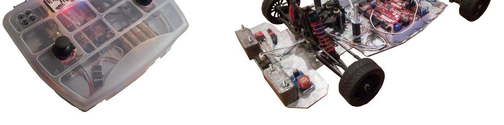
21 Explorer vehicle


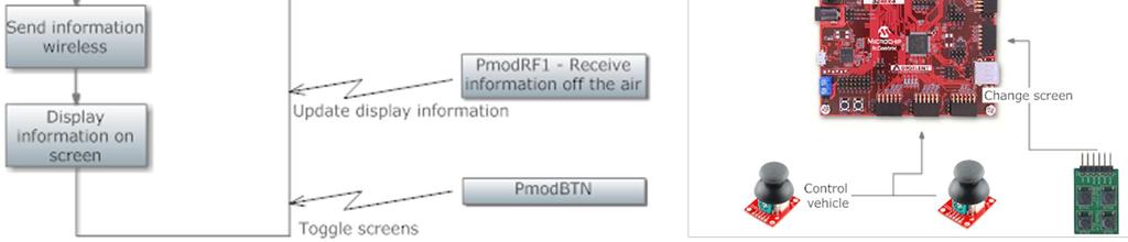
22 Remote control & sensing module Explorer vehicle


 Servo motor")
23 Actuators and sensors module Explorer vehicle 50Hz, 1 2 ms puls width: 1 ms - lowest level 2 ms - highest level 1.5 ms neutral (start up) Electronic Speed Controller (ESC) Brushless DC motor (propulsion) Servo motor (steering)


24 Explorer vehicle
25 Stepper motors Motor controlled by a series of electromagnetic coils. Build: center magnetic shaft surrounded by coils The coils are alternately given current or not, creating magnetic fields which repulse or attract the magnets on the shaft, causing the motor to rotate. This design allows for very precise control of the motor: by proper pulsing, it can be turned in very accurate steps of set degree increments (for example, twodegree increments, half-degree increments, etc.). They are used in printers, disk drives, and other devices where precise positioning of the motor is necessary. Two phase & higher count phase stepper motors There are 2 basic types of two phase stepper motors: Refrences - unipolar steppers (simple commutation circuit: 1 transistor / winding) - bipolar steppers (more complicated driving circuit usually H bridge) [1] [2] [3] M. Margolis, Arduino Cookbook, 2-nd Edition, O Reilly, 2012.
![Stepper motors Unipolar steppers [2] Ex: wave drive motor (3.](/docs-images/80/82453063/images/26-0.jpg "6 /step) Wave drive or Full step drive (one phase on) - Low torque / rarely used (ex: 25")

 / x2 resolution (ex: 8 steps to rotate by 1 teeth position 25*8 = 200 steps")
26 Stepper motors Unipolar steppers [2] Ex: wave drive motor (3.6 /step) Wave drive or Full step drive (one phase on) - Low torque / rarely used (ex: 25 teeth / 4 steps to rotate by one teeth position 25*4 = 100 steps per full rotation each step will be 360/100 = 3.6 Full step drive (two phases on) - Maximum rated torque (most used) Half stepping - Lower torque (70%) / x2 resolution (ex: 8 steps to rotate by 1 teeth position 25*8 = 200 steps per full rotation each step 360/200 = 1.8 Microstepping - Increased resolution / smoother operation
27 Stepper motors Arduino Stepper Library ( - allows you to control unipolar or bipolar stepper motors. To use it you will need a stepper motor, and the appropriate hardware (driver) to control it. To create a new instance of the Stepper motor class Stepper(steps, pin1, pin2) - ex: Stepper mystepper = Stepper(100, 5, 6); Stepper(steps, pin1, pin2, pin3, pin4) int steps: the number of steps / revolution (e.g. 360 / 3.6 = 100 steps) int pin1, pin2: two pins that are attached to the driver (2 pin setup) int pin3, pin4: optional the last two pins attached to the driver (4 pin setup) Control sequence (2 wire setup): Step wire 1 wire 2 1 low high 2 high high 3 high low 4 low low 2 pin/wire setup
28 Control sequence (4 wire setup): Stepper motors Step wire 1 wire 2 wire 3 wire 4 1 High low high low 2 low high high low 3 low high low high 4 high low low high With the use of the Arduino Stepper Library, the control signals are generated by the library!!!! Example of motor driver: U2004 Darlington Array - high voltage, high current Darlington arrays each containing seven open collector Darlington pairs with common emitters. Each channel rated at 500 ma and can withstand peak currents of 600 ma. 4 pin / wire setup
29 Stepper motors Arduino Stepper Library ( setspeed(long rpms) - Sets the motor speed in rotations per minute (RPMs). This function doesn't make the motor turn, just sets the speed at which it will when you call step(). step(int steps) - Turns the motor a specific number of steps, at a speed determined by the most recent call to setspeed(). int steps: the number of steps to turn the motor positive(+) to turn one direction, negative(-) to turn the other This function is blocking: it will wait until the motor has finished moving to pass control to the next line in your sketch. (Ec: speed = 1 RPM and called step(100) on a 100-step motor the function would take a full minute to run. For better control, keep the speed high and only go a few steps with each call to step().
30 Stepper motors Example: Stepper Motor Knob ( step numbers of a unipolar stepper (4 wire driver setup) controlled by a potentiometer #include <Stepper.h> #define STEPS 100 void loop() { // get the sensor / potentiometer reading int val = analogread(0); // move a number of steps equal to the change in the sensor reading stepper.step(val - previous); // remember the previous value of the sensor previous = val; } Stepper stepper(steps, 8, 9, 10, 11); // the previous reading from the analog input int previous = 0; void setup() { // set the speed of the motor to 30 RPMs stepper.setspeed(30); }
31 Stepper motors Example: unipolar stepper (4 wire driver setup) controlled using commands from the serial port: numeric_value (0 9) followed by + steps in one direction; followed by - steps in the other (M. Margolis, Arduino Cookbook, 2-nd Edition, O Reilly, 2012) #include <Stepper.h> #define STEPS 24 Stepper stepper(steps, 2, 3, 4, 5); int steps = 0; void setup() { stepper.setspeed(30); // motor speed [RPM] Serial.begin(9600); } void loop() { if ( Serial.available()) { char ch = Serial.read(); if(isdigit(ch)) { // is ch a number? steps = steps * 10 + ch - '0'; // yes, accumulate the value } else if(ch == '+'){ stepper.step(steps); steps = 0; } else if(ch == '-'){ stepper.step(steps * -1); steps = 0; } else if(ch == 's'){ stepper.setspeed(steps); Serial.print("Setting speed to "); Serial.println(steps); steps = 0; } } }
Figure 1. Digilent DC Motor
 Laboratory 9 - Usage of DC- and servo-motors The current laboratory describes the usage of DC and servomotors 1. DC motors Figure 1. Digilent DC Motor Classical DC motors are converting electrical energy
Learning Objectives. References 10/26/11. Using servos with an Arduino. EAS 199A Fall 2011
 Using servos with an Arduino EAS 199A Fall 2011 Learning Objectives Be able to identify characteristics that distinguish a servo and a DC motor Be able to describe the difference a conventional servo and
Using Servos with an Arduino
 Using Servos with an Arduino ME 120 Mechanical and Materials Engineering Portland State University http://web.cecs.pdx.edu/~me120 Learning Objectives Be able to identify characteristics that distinguish
Mechatronics Engineering and Automation Faculty of Engineering, Ain Shams University MCT-151, Spring 2015 Lab-4: Electric Actuators
 Mechatronics Engineering and Automation Faculty of Engineering, Ain Shams University MCT-151, Spring 2015 Lab-4: Electric Actuators Ahmed Okasha, Assistant Lecturer okasha1st@gmail.com Objective Have a
Assignments from last week
 Assignments from last week Review LED flasher kits Review protoshields Need more soldering practice (see below)? http://www.allelectronics.com/make-a-store/category/305/kits/1.html http://www.mpja.com/departments.asp?dept=61
Arduino. AS220 Workshop. Part II Interactive Design with advanced Transducers Lutz Hamel
 AS220 Workshop Part II Interactive Design with advanced Transducers Lutz Hamel hamel@cs.uri.edu www.cs.uri.edu/~hamel/as220 How we see the computer Image source: Considering the Body, Kate Hartman, 2008.
Design with Microprocessors
 Design with Microprocessors Lecture 9 Year 3 CS Academic year 2017/2018 1 st Semester Lecturer: Radu Dănescu Analog Comparator AIN+ AIN- Compares the analog values from AIN+ (positive) & AIN- (negative)
100UF CAPACITOR POTENTIOMETER SERVO MOTOR MOTOR ARM. MALE HEADER PIN (3 pins) INGREDIENTS
 INGREDIENTS") 05 POTENTIOMETER SERVO MOTOR MOTOR ARM 100UF CAPACITOR MALE HEADER PIN (3 pins) INGREDIENTS 63 MOOD CUE USE A SERVO MOTOR TO MAKE A MECHANICAL GAUGE TO POINT OUT WHAT SORT OF MOOD YOU RE IN THAT DAY Discover:
05 POTENTIOMETER SERVO MOTOR MOTOR ARM 100UF CAPACITOR MALE HEADER PIN (3 pins) INGREDIENTS 63 MOOD CUE USE A SERVO MOTOR TO MAKE A MECHANICAL GAUGE TO POINT OUT WHAT SORT OF MOOD YOU RE IN THAT DAY Discover:
combine regular DC-motors with a gear-box and an encoder/potentiometer to form a position control loop can only assume a limited range of angular
 Embedded Control Applications II MP10-1 Embedded Control Applications II MP10-2 week lecture topics 10 Embedded Control Applications II - Servo-motor control - Stepper motor control - The control of a
HAW-Arduino. Sensors and Arduino F. Schubert HAW - Arduino 1
 HAW-Arduino Sensors and Arduino 14.10.2010 F. Schubert HAW - Arduino 1 Content of the USB-Stick PDF-File of this script Arduino-software Source-codes Helpful links 14.10.2010 HAW - Arduino 2 Report for
Lecture 6. Interfacing Digital and Analog Devices to Arduino. Intro to Arduino
 Lecture 6 Interfacing Digital and Analog Devices to Arduino. Intro to Arduino PWR IN USB (to Computer) RESET SCL\SDA (I2C Bus) POWER 5V / 3.3V / GND Analog INPUTS Digital I\O PWM(3, 5, 6, 9, 10, 11) Components
2.017 DESIGN OF ELECTROMECHANICAL ROBOTIC SYSTEMS Fall 2009 Lab 4: Motor Control. October 5, 2009 Dr. Harrison H. Chin
 2.017 DESIGN OF ELECTROMECHANICAL ROBOTIC SYSTEMS Fall 2009 Lab 4: Motor Control October 5, 2009 Dr. Harrison H. Chin Formal Labs 1. Microcontrollers Introduction to microcontrollers Arduino microcontroller
Arduino Control of Tetrix Prizm Robotics. Motors and Servos Introduction to Robotics and Engineering Marist School
 Arduino Control of Tetrix Prizm Robotics Motors and Servos Introduction to Robotics and Engineering Marist School Motor or Servo? Motor Faster revolution but less Power Tetrix 12 Volt DC motors have a
MICROCONTROLLERS Stepper motor control with Sequential Logic Circuits
 PH-315 MICROCONTROLLERS Stepper motor control with Sequential Logic Circuits Portland State University Summary Four sequential digital waveforms are used to control a stepper motor. The main objective
Disclaimer. Arduino Hands-On 2 CS5968 / ART4455 9/1/10. ! Many of these slides are mine. ! But, some are stolen from various places on the web
 Arduino Hands-On 2 CS5968 / ART4455 Disclaimer! Many of these slides are mine! But, some are stolen from various places on the web! todbot.com Bionic Arduino and Spooky Arduino class notes from Tod E.Kurt!
Actuators. DC Motor Servo Motor Stepper Motor. Sensors
 Actuators Sensors 2 Actuators DC Motor Servo Motor Stepper Motor Sensors 3 1. The stator generates a stationary magnetic field surrounding the rotor. 2. The rotor/armature is composed of a coil which generates
ABCs of Arduino. Kurt Turchan -
 ABCs of Arduino Kurt Turchan - kurt@trailpeak.com Bio: Kurt is a web designer (java/php/ui-jquery), project manager, instructor (PHP/HTML/...), and arduino enthusiast, Kurt is founder of www.trailpeak.com
Arduino and Servo Motor
 Arduino and Servo Motor 1. Basics of the Arduino Board and Arduino a. Arduino is a mini computer that can input and output data using the digital and analog pins b. Arduino Shield: mounts on top of Arduino
Arduino Digital Out_QUICK RECAP
 Arduino Digital Out_QUICK RECAP BLINK File> Examples>Digital>Blink int ledpin = 13; // LED connected to digital pin 13 // The setup() method runs once, when the sketch starts void setup() // initialize
L E C T U R E R, E L E C T R I C A L A N D M I C R O E L E C T R O N I C E N G I N E E R I N G
 P R O F. S L A C K L E C T U R E R, E L E C T R I C A L A N D M I C R O E L E C T R O N I C E N G I N E E R I N G G B S E E E @ R I T. E D U B L D I N G 9, O F F I C E 0 9-3 1 8 9 ( 5 8 5 ) 4 7 5-5 1 0
Experiment#6: Speaker Control
 Experiment#6: Speaker Control I. Objectives 1. Describe the operation of the driving circuit for SP1 speaker. II. Circuit Description The circuit of speaker and driver is shown in figure# 1 below. The
Programming a Servo. Servo. Red Wire. Black Wire. White Wire
 Programming a Servo Learn to connect wires and write code to program a Servo motor. If you have gone through the LED Circuit and LED Blink exercises, you are ready to move on to programming a Servo. A
Using Transistors and Driving Motors
 Chapter 4 Using Transistors and Driving Motors Parts You ll Need for This Chapter: Arduino Uno USB cable 9V battery 9V battery clip 5V L4940V5 linear regulator 22uF electrolytic capacitor.1uf electrolytic
Embedded Systems Lab Lab 7 Stepper Motor Application
 Islamic University of Gaza College of Engineering puter Department Embedded Systems Lab Stepper Motor Application Prepared By: Eng.Ola M. Abd El-Latif Apr. /2010 :D 0 Objective Tools Theory To realize
Sensors and Sensing Motors, Encoders and Motor Control
 Sensors and Sensing Motors, Encoders and Motor Control Todor Stoyanov Mobile Robotics and Olfaction Lab Center for Applied Autonomous Sensor Systems Örebro University, Sweden todor.stoyanov@oru.se 13.11.2014
Assembly Language. Topic 14 Motion Control. Stepper and Servo Motors
 Assembly Language Topic 14 Motion Control Stepper and Servo Motors Objectives To gain an understanding of the operation of a stepper motor To develop a means to control a stepper motor To gain an understanding
Lab Exercise 9: Stepper and Servo Motors
 ME 3200 Mechatronics Laboratory Lab Exercise 9: Stepper and Servo Motors Introduction In this laboratory exercise, you will explore some of the properties of stepper and servomotors. These actuators are
Motors and Servos Part 2: DC Motors
 Motors and Servos Part 2: DC Motors Back to Motors After a brief excursion into serial communication last week, we are returning to DC motors this week. As you recall, we have already worked with servos
FABO ACADEMY X ELECTRONIC DESIGN
 ELECTRONIC DESIGN MAKE A DEVICE WITH INPUT & OUTPUT The Shanghaino can be programmed to use many input and output devices (a motor, a light sensor, etc) uploading an instruction code (a program) to it
Sensors and Sensing Motors, Encoders and Motor Control
 Sensors and Sensing Motors, Encoders and Motor Control Todor Stoyanov Mobile Robotics and Olfaction Lab Center for Applied Autonomous Sensor Systems Örebro University, Sweden todor.stoyanov@oru.se 05.11.2015
Stepper Motors in C. Unipolar (5 lead) stepper motorr. $1.95 from 100 steps per rotation. 24V / 160mA / 600 gm cm holding 160mA
 stepper motorr. $1.95 from 100 steps per rotation. 24V / 160mA / 600 gm cm holding 160mA") U tepper Motors ugust 22, 2017 tepper Motors in Unipolar (5 lead) stepper motorr. $1.95 from www.mpja.com 100 steps per rotation. 24V / 160m / 600 gm cm holding torque @ 160m stepper motor is a digital
U tepper Motors ugust 22, 2017 tepper Motors in Unipolar (5 lead) stepper motorr. $1.95 from www.mpja.com 100 steps per rotation. 24V / 160m / 600 gm cm holding torque @ 160m stepper motor is a digital
Lecture 4: Basic Electronics. Lecture 4 Brief Introduction to Electronics and the Arduino
 Lecture 4: Basic Electronics Lecture 4 Page: 1 Brief Introduction to Electronics and the Arduino colintan@nus.edu.sg Lecture 4: Basic Electronics Page: 2 Objectives of this Lecture By the end of today
Administrative Notes. DC Motors; Torque and Gearing; Encoders; Motor Control. Today. Early DC Motors. Friday 1pm: Communications lecture
 At Actuation: ti DC Motors; Torque and Gearing; Encoders; Motor Control RSS Lecture 3 Wednesday, 11 Feb 2009 Prof. Seth Teller Administrative Notes Friday 1pm: Communications lecture Discuss: writing up
EE 308 Spring S12 SUBSYSTEMS: PULSE WIDTH MODULATION, A/D CONVERTER, AND SYNCHRONOUS SERIAN INTERFACE
 9S12 SUBSYSTEMS: PULSE WIDTH MODULATION, A/D CONVERTER, AND SYNCHRONOUS SERIAN INTERFACE In this sequence of three labs you will learn to use the 9S12 S hardware sybsystem. WEEK 1 PULSE WIDTH MODULATION
MOBILE ROBOT LOCALIZATION with POSITION CONTROL
 T.C. DOKUZ EYLÜL UNIVERSITY ENGINEERING FACULTY ELECTRICAL & ELECTRONICS ENGINEERING DEPARTMENT MOBILE ROBOT LOCALIZATION with POSITION CONTROL Project Report by Ayhan ŞAVKLIYILDIZ - 2011502093 Burcu YELİS
1. Introduction to Analog I/O
 EduCake Analog I/O Intro 1. Introduction to Analog I/O In previous chapter, we introduced the 86Duino EduCake, talked about EduCake s I/O features and specification, the development IDE and multiple examples
J. La Favre Using Arduino with Raspberry Pi February 7, 2018
 As you have already discovered, the Raspberry Pi is a very capable digital device. Nevertheless, it does have some weaknesses. For example, it does not produce a clean pulse width modulation output (unless
C++ PROGRAM FOR DRIVING OF AN AGRICOL ROBOT
 Annals of the University of Petroşani, Mechanical Engineering, 14 (2012), 11-19 11 C++ PROGRAM FOR DRIVING OF AN AGRICOL ROBOT STELIAN-VALENTIN CASAVELA 1 Abstract: This robot is projected to participate
E11 Lecture 11: Sensors & Actuators. Profs. David Money Harris & Sarah Harris Fall 2011
 E11 Lecture 11: Sensors & Actuators Profs. David Money Harris & Sarah Harris Fall 2011 Outline Actuators DC Motor Servo Motor Stepper Motor Sensors Phototransistor Reflectance Sensor IR Distance Sensor
Brushed DC Motor Microcontroller PWM Speed Control with Optical Encoder and H-Bridge
 Brushed DC Motor Microcontroller PWM Speed Control with Optical Encoder and H-Bridge L298 Full H-Bridge HEF4071B OR Gate Brushed DC Motor with Optical Encoder & Load Inertia Flyback Diodes Arduino Microcontroller
Parts List. Robotic Arm segments ¼ inch screws Cable XBEE module or Wifi module
 Robotic Arm 1 Legal Stuff Stensat Group LLC assumes no responsibility and/or liability for the use of the kit and documentation. There is a 90 day warranty for the Sten-Bot kit against component defects.
EEE3410 Microcontroller Applications Department of Electrical Engineering Lecture 11 Motor Control
 EEE34 Microcontroller Applications Department of Electrical Engineering Lecture Motor Control Week 3 EEE34 Microcontroller Applications In this Lecture. Interface 85 with the following output Devices Optoisolator
ES86 Series Closed-loop Stepper Drive + Motor System (Drive+ Motor/Encoder)
") ES86 Series Closed-loop Stepper Drive + Motor System (Drive+ Motor/Encoder) Traditional stepper motor drive systems operate open loop providing position control without feedback. However, because of this,
ES86 Series Closed-loop Stepper Drive + Motor System (Drive+ Motor/Encoder) Traditional stepper motor drive systems operate open loop providing position control without feedback. However, because of this,
Servo Sweep. Learn to make a regular Servo move in a sweeping motion.
 Servo Sweep Learn to make a regular Servo move in a sweeping motion. We have seen how to control a Servo and also how to make an LED Fade on and off. This activity will teach you how to make a regular
EXPERIMENT 6: Advanced I/O Programming
 EXPERIMENT 6: Advanced I/O Programming Objectives: To familiarize students with DC Motor control and Stepper Motor Interfacing. To utilize MikroC and MPLAB for Input Output Interfacing and motor control.
Laboratory Exercise 1 Microcontroller Board with Driver Board
 Laboratory Exercise 1 Microcontroller Board with Driver Board The purpose of this lab exercises is to demonstrate how the Microcontroller Board can be used to control motors connected to the Driver Board
Attribution Thank you to Arduino and SparkFun for open source access to reference materials.
 Attribution Thank you to Arduino and SparkFun for open source access to reference materials. Contents Parts Reference... 1 Installing Arduino... 7 Unit 1: LEDs, Resistors, & Buttons... 7 1.1 Blink (Hello
Physics 124: Lecture 3. Three Types (for us) Motors: Servo; DC; Stepper Messing with PWM (and 2- way serial) The Motor Shield.
 Motors: Servo; DC; Stepper Messing with PWM (and 2- way serial) The Motor Shield.") Physics 124: Lecture 3 Motors: Servo; DC; Stepper Messing with PWM (and 2- way serial) The Motor Shield Servo motor Three Types (for us) PWM sets posijon, used for R/C planes, cars, etc. 180 range limit,
Physics 124: Lecture 3 Motors: Servo; DC; Stepper Messing with PWM (and 2- way serial) The Motor Shield Servo motor Three Types (for us) PWM sets posijon, used for R/C planes, cars, etc. 180 range limit,
Yihao Qian Team A: Aware Teammates: Amit Agarwal Harry Golash Menghan Zhang Zihao (Theo) Zhang ILR01 Oct.14, 2016
 Zhang ILR01 Oct.14, 2016") Yihao Qian Team A: Aware Teammates: Amit Agarwal Harry Golash Menghan Zhang Zihao (Theo) Zhang ILR01 Oct.14, 2016 Individual Progress For sensors and motors lab, I was in charge of the servo and force
Yihao Qian Team A: Aware Teammates: Amit Agarwal Harry Golash Menghan Zhang Zihao (Theo) Zhang ILR01 Oct.14, 2016 Individual Progress For sensors and motors lab, I was in charge of the servo and force
4WD Mobile Platform SKU:ROB0022
 4WD Mobile Platform SKU:ROB0022 Contents [hide] 1 Function Introduction 1.1 STEP1: Assemble Robot 1.2 STEP2: Debug Motor 1.3 STEP3:Install Upper Plate 1.4 STEP4: Debug Ultrasonic Sensor and Servo 1.5 STEP5:
ServoStep technology
 What means "ServoStep" "ServoStep" in Ever Elettronica's strategy resumes seven keypoints for quality and performances in motion control applications: Stepping motors Fast Forward Feed Full Digital Drive
Arduino Application: Speed control of small DC Motors
 Arduino Application: Speed control of small DC Motors ME 120 Mechanical and Materials Engineering Portland State University http://web.cecs.pdx.edu/~me120 Learning Objectives Be able to describe the use
ES86 Series Closed-loop Stepper Drive + Motor System (Drive+ Motor/Encoder)
") ES86 Series Closed-loop Stepper Drive + Motor System (Drive+ Motor/Encoder) Traditional stepper motor drive systems operate open loop providing position control without feedback. However, because of this,
ES86 Series Closed-loop Stepper Drive + Motor System (Drive+ Motor/Encoder) Traditional stepper motor drive systems operate open loop providing position control without feedback. However, because of this,
THE IMPORTANCE OF PLANNING AND DRAWING IN DESIGN
 PROGRAM OF STUDY ENGR.ROB Standard 1 Essential UNDERSTAND THE IMPORTANCE OF PLANNING AND DRAWING IN DESIGN The student will understand and implement the use of hand sketches and computer-aided drawing
Coding with Arduino to operate the prosthetic arm
 Setup Board Install FTDI Drivers This is so that your RedBoard will be able to communicate with your computer. If you have Windows 8 or above you might already have the drivers. 1. Download the FTDI driver
EE 314 Spring 2003 Microprocessor Systems
 EE 314 Spring 2003 Microprocessor Systems Laboratory Project #9 Closed Loop Control Overview and Introduction This project will bring together several pieces of software and draw on knowledge gained in
Feed-back loop. open-loop. closed-loop
 Servos AJLONTECH Overview Servo motors are used for angular positioning, such as in radio control airplanes. They typically have a movement range of 180 deg but can go up to 210 deg. The output shaft of
SMART Funded by The National Science Foundation
 Lecture 5 Capacitors 1 Store electric charge Consists of two plates of a conducting material separated by a space filled by an insulator Measured in units called farads, F Capacitors 2 Mylar Ceramic Electrolytic
CONSTRUCTION GUIDE Robotic Arm. Robobox. Level II
 CONSTRUCTION GUIDE Robotic Arm Robobox Level II Robotic Arm This month s robot is a robotic arm with two degrees of freedom that will teach you how to use motors. You will then be able to move the arm
Electronic Speed Controls and RC Motors
 Electronic Speed Controls and RC Motors ESC Power Control Modern electronic speed controls regulate the electric power applied to an electric motor by rapidly switching the power on and off using power
ES86 Series Closed-loop Stepper Drive + Motor System (ES-D808 Drive+ Motor/Encoder)
") ES86 Series Closed-loop Stepper Drive + Motor System (ES-D808 Drive+ Motor/Encoder) Traditional stepper motor drive systems operate open loop providing position control without feedback. However, because
ES86 Series Closed-loop Stepper Drive + Motor System (ES-D808 Drive+ Motor/Encoder) Traditional stepper motor drive systems operate open loop providing position control without feedback. However, because
Lab 5: Inverted Pendulum PID Control
 Lab 5: Inverted Pendulum PID Control In this lab we will be learning about PID (Proportional Integral Derivative) control and using it to keep an inverted pendulum system upright. We chose an inverted
ECE 477 Digital Systems Senior Design Project Rev 8/09. Homework 5: Theory of Operation and Hardware Design Narrative
 ECE 477 Digital Systems Senior Design Project Rev 8/09 Homework 5: Theory of Operation and Hardware Design Narrative Team Code Name: _ATV Group No. 3 Team Member Completing This Homework: Sebastian Hening
Chapter 7: The motors of the robot
 Chapter 7: The motors of the robot Learn about different types of motors Learn to control different kinds of motors using open-loop and closedloop control Learn to use motors in robot building 7.1 Introduction
STEPPER MOTORS. Intro to Stepper Motors
 STEPPER MOTORS Intro to Stepper Motors DC motors with precise control of how far they spin They have a fixed number of steps the take to turn one full revolution You can control them one step at a time
The Motor sketch. One Direction ON-OFF DC Motor
 One Direction ON-OFF DC Motor The DC motor in your Arduino kit is the most basic of electric motors and is used in all types of hobby electronics. When current is passed through, it spins continuously
νµθωερτψυιοπασδφγηϕκλζξχϖβνµθωερτ ψυιοπασδφγηϕκλζξχϖβνµθωερτψυιοπα σδφγηϕκλζξχϖβνµθωερτψυιοπασδφγηϕκ χϖβνµθωερτψυιοπασδφγηϕκλζξχϖβνµθ
 θωερτψυιοπασδφγηϕκλζξχϖβνµθωερτψ υιοπασδφγηϕκλζξχϖβνµθωερτψυιοπασδ φγηϕκλζξχϖβνµθωερτψυιοπασδφγηϕκλζ ξχϖβνµθωερτψυιοπασδφγηϕκλζξχϖβνµ EE 331 Design Project Final Report θωερτψυιοπασδφγηϕκλζξχϖβνµθωερτψ
USER S GUIDE POLOLU A4988 STEPPER MOTOR DRIVER CARRIER USING THE DRIVER POWER CONNECTIONS
 POLOLU A4988 STEPPER MOTOR DRIVER CARRIER USER S GUIDE USING THE DRIVER Minimal wiring diagram for connecting a microcontroller to an A4988 stepper motor driver carrier (full-step mode). POWER CONNECTIONS
Operating Mode: Serial; (PWM) passive control mode; Autonomous Mode; On/OFF Mode
 passive control mode; Autonomous Mode; On/OFF Mode") RB-Dfr-11 DFRobot URM V3.2 Ultrasonic Sensor URM37 V3.2 Ultrasonic Sensor uses an industrial level AVR processor as the main processing unit. It comes with a temperature correction which is very unique
RB-Dfr-11 DFRobot URM V3.2 Ultrasonic Sensor URM37 V3.2 Ultrasonic Sensor uses an industrial level AVR processor as the main processing unit. It comes with a temperature correction which is very unique
Marine Debris Cleaner Phase 1 Navigation
 Southeastern Louisiana University Marine Debris Cleaner Phase 1 Navigation Submitted as partial fulfillment for the senior design project By Ryan Fabre & Brock Dickinson ET 494 Advisor: Dr. Ahmad Fayed
Autonomous Following RObot Initial Design Review
 Autonomous Following RObot Initial Design Review James Tse (Leader) Wei Dai Travis Frecker Peter Verlangieri Professor John Johnson ECE 189A Fall 2012 Initial Design Review: Project Description Original
URM37 V3.2 Ultrasonic Sensor (SKU:SEN0001)
") URM37 V3.2 Ultrasonic Sensor (SKU:SEN0001) From Robot Wiki Contents 1 Introduction 2 Specification 2.1 Compare with other ultrasonic sensor 3 Hardware requierments 4 Tools used 5 Software 6 Working Mode
URM37 V3.2 Ultrasonic Sensor (SKU:SEN0001) From Robot Wiki Contents 1 Introduction 2 Specification 2.1 Compare with other ultrasonic sensor 3 Hardware requierments 4 Tools used 5 Software 6 Working Mode
Introduction: Components used:
 Introduction: As, this robotic arm is automatic in a way that it can decides where to move and when to move, therefore it works in a closed loop system where sensor detects if there is any object in a
AN Industrial Stepper Motor Driver. Application Note Abstract. Introduction. Stepper Motor Control Method
 Industrial Stepper Motor Driver AN43679 Author: Dino Gu, Bill Jiang, Jemmey Huang Associated Project: Yes Associated Part Family: CY8C27x43, CY8C29x66 GET FREE SAMPLES HERE Software Version: PSoC Designer
LED + Servo 2 devices, 1 Arduino
 LED + Servo 2 devices, 1 Arduino Learn to connect and write code to control both a Servo and an LED at the same time. Many students who come through the lab ask if they can use both an LED and a Servo
Application Note: Using the Motor Driver on the 3pi Robot and Orangutan Robot Controllers
 Application Note: Using the Motor Driver on the 3pi Robot and Orangutan Robot 1. Introduction..................................................... 2 2. Motor Driver Truth Tables.............................................
EE 308 Lab Spring 2009
 9S12 Subsystems: Pulse Width Modulation, A/D Converter, and Synchronous Serial Interface In this sequence of three labs you will learn to use three of the MC9S12's hardware subsystems. WEEK 1 Pulse Width
Programming PIC Microchips
 Programming PIC Microchips Fís Foghlaim Forbairt Programming the PIC microcontroller using Genie Programming Editor Workshop provided & facilitated by the PDST www.t4.ie Page 1 DC motor control: DC motors
DUAL STEPPER MOTOR DRIVER
 DUAL STEPPER MOTOR DRIVER GENERAL DESCRIPTION The is a switch-mode (chopper), constant-current driver with two channels: one for each winding of a two-phase stepper motor. is equipped with a Disable input
LS7362 BRUSHLESS DC MOTOR COMMUTATOR / CONTROLLER
 LS7362 BRUSHLESS DC MOTOR COMMUTATOR / CONTROLLER FEATURES: Speed control by Pulse Width Modulating (PWM) only the low-side drivers reduces switching losses in level converter circuitry for high voltage
Module 13: Interfacing ADC. Introduction ADC Programming DAC Programming Sensor Interfacing
 Module 13: Interfacing ADC Introduction ADC Programming DAC Programming Sensor Interfacing Introduction ADC Devices o Analog-to-digital converters (ADC) are among the most widely used devices for data
Datasheet of the MEZ Stepper Servo Drive MEZ 2D VDC, 8.2A Peak, Closed-loop, No Tuning. Version
 Datasheet of the MEZ Stepper Servo Drive MEZ D880 4-75VDC, 8.A Peak, Closed-loop, No Tuning Version 0.1.1 http://www.motionking.com Features Step and direction control Closed position loop for no loss
Automobile Prototype Servo Control
 IJIRST International Journal for Innovative Research in Science & Technology Volume 2 Issue 10 March 2016 ISSN (online): 2349-6010 Automobile Prototype Servo Control Mr. Linford William Fernandes Don Bosco
Lab 06: Ohm s Law and Servo Motor Control
 CS281: Computer Systems Lab 06: Ohm s Law and Servo Motor Control The main purpose of this lab is to build a servo motor control circuit. As with prior labs, there will be some exploratory sections designed
FRIDAY, 18 MAY 1.00 PM 4.00 PM. Where appropriate, you may use sketches to illustrate your answer.
 X036/13/01 NATIONAL QUALIFICATIONS 2012 FRIDAY, 18 MAY 1.00 PM 4.00 PM TECHNOLOGICAL STUDIES ADVANCED HIGHER 200 marks are allocated to this paper. Answer all questions in Section A (120 marks). Answer
PIC Functionality. General I/O Dedicated Interrupt Change State Interrupt Input Capture Output Compare PWM ADC RS232
 PIC Functionality General I/O Dedicated Interrupt Change State Interrupt Input Capture Output Compare PWM ADC RS232 General I/O Logic Output light LEDs Trigger solenoids Transfer data Logic Input Monitor
HBS Series Hybrid Servos
 Hybrid Servos 46 Hybrid Servos From the stepper and servo, but surpass them in many applications! HBS Series Hybrid Servos Closed-loop, eliminates loss of synchronization The HBS series use an encoder
Hobby Servo Tutorial. Introduction. Sparkfun: https://learn.sparkfun.com/tutorials/hobby-servo-tutorial
 Hobby Servo Tutorial Sparkfun: https://learn.sparkfun.com/tutorials/hobby-servo-tutorial Introduction Servo motors are an easy way to add motion to your electronics projects. Originally used in remotecontrolled
Sensor and. Motor Control Lab. Abhishek Bhatia. Individual Lab Report #1
 Sensor and 10/16/2015 Motor Control Lab Individual Lab Report #1 Abhishek Bhatia Team D: Team HARP (Human Assistive Robotic Picker) Teammates: Alex Brinkman, Feroze Naina, Lekha Mohan, Rick Shanor I. Individual
ME 461 Laboratory #5 Characterization and Control of PMDC Motors
 ME 461 Laboratory #5 Characterization and Control of PMDC Motors Goals: 1. Build an op-amp circuit and use it to scale and shift an analog voltage. 2. Calibrate a tachometer and use it to determine motor
Follow this and additional works at: Part of the Engineering Commons
 Trinity University Digital Commons @ Trinity Mechatronics Final Projects Engineering Science Department 5-2016 Heart Beat Monitor Ivan Mireles Trinity University, imireles@trinity.edu Sneha Pottian Trinity
DC motor control using arduino
 DC motor control using arduino 1) Introduction: First we need to differentiate between DC motor and DC generator and where we can use it in this experiment. What is the main different between the DC-motor,
Job Sheet 2 Servo Control
 Job Sheet 2 Servo Control Electrical actuators are replacing hydraulic actuators in many industrial applications. Electric servomotors and linear actuators can perform many of the same physical displacement
Lesson4 Obstacle avoidance car
 Lesson4 Obstacle avoidance car 1 Points of this section The joy of learning, is not just know how to control your car, but also know how to protect your car. So, make you car far away from collision. Learning
Electronics, Sensors, and Actuators
 Electronics, Sensors, and Actuators 4/14/15 David Flicker BE107 Overview Basic electronics and components Sensors Actuators Electronics 101 Voltage, V, is fundamentally how much energy is gained or lost
RC Servo Interface. Figure Bipolar amplifier connected to a large DC motor
 The bipolar amplifier is well suited for controlling motors for vehicle propulsion. Figure 12-45 shows a good-sized 24VDC motor that runs nicely on 13.8V from a lead acid battery based power supply. You
B RoboClaw 2 Channel 30A Motor Controller Data Sheet
 B0098 - RoboClaw 2 Channel 30A Motor Controller (c) 2010 BasicMicro. All Rights Reserved. Feature Overview: 2 Channel at 30Amp, Peak 60Amp Battery Elimination Circuit (BEC) Switching Mode BEC Hobby RC
Implementation of Brushless DC motor speed control on STM32F407 Cortex M4
 Implementation of Brushless DC motor speed control on STM32F407 Cortex M4 Mr. Kanaiya G Bhatt 1, Mr. Yogesh Parmar 2 Assistant Professor, Assistant Professor, Dept. of Electrical & Electronics, ITM Vocational
MICROPROCESSORS A (17.383) Fall Lecture Outline
 Fall Lecture Outline") MICROPROCESSORS A (17.383) Fall 2010 Lecture Outline Class # 07 October 26, 2010 Dohn Bowden 1 Today s Lecture Syllabus review Microcontroller Hardware and/or Interface Finish Analog to Digital Conversion
MICROPROCESSORS A (17.383) Fall 2010 Lecture Outline Class # 07 October 26, 2010 Dohn Bowden 1 Today s Lecture Syllabus review Microcontroller Hardware and/or Interface Finish Analog to Digital Conversion
Analog Feedback Servos
 Analog Feedback Servos Created by Bill Earl Last updated on 2018-01-21 07:07:32 PM UTC Guide Contents Guide Contents About Servos and Feedback What is a Servo? Open and Closed Loops Using Feedback Reading