1- A hypothetical isotropic antenna is radiating in free-space. At a distance of 100 m from the antenna, the total electric field (E θ
|
|
|
- Shanna West
- 5 years ago
- Views:
Transcription
1 1- A two way communication link has a eceive with a minimum detectable signal of -55 dbm. The eceive antenna gain is 35 db and the tansmitte antenna gain is 4 db. The caie fequency is 4 GHz, and the distance between the tansmitte and the eceive is 6 km. Suppose that it stats aining and the attenuation though the atmosphee is. db/km. What should the minimum tansmitte powe be so that the signal can be detected by the eceive? P = 55 dbm = 3.16 nw, G = 35 db = 316, G = 4 db = 1, t λ =.15 m, d = 6 km, Loss = (6 km)(.db km) = 1dB 1 P λ t = P GG t( 4 d) π =.364 W = 5.6 dbm Pt = P t + 1 db = 37.6 dbm 1- A hypothetical isotopic antenna is adiating in fee-space. At a distance of 1 m fom the antenna, the total electic field (E θ ) is measued to be 5 V/m. Find the powe density and powe adiated. S ( E H ) aˆ.3315 aˆ W m 1 av η π π π π P = S sinθdθdφ =.3315 sinθdθdφ = W ad E = = = av
2 3- An antenna has its fa field (electic field) in the fee space given below whee is the distance of the obsevation point fom the antenna. a) Find the total adiated powe of the antenna. b) Find the adiation esistance if the feeding cuent fo the antenna I in is.1 A. jk e E() θ = cos θ a ˆθ(Vm) Eθ 1 cosθ Sav = = η η π π 1 π π π π Pad = av sin cos sin cos sin.56 S θdθdφ = θ θdθdφ θ θdθ η = η = 1 Pad Pad = Iin R R = = 11Ω I in 1- An antenna has a adiated electic field as defined below, whee I is the feed point cuent, and η is the intinsic impedance of fee space. a) Find the time aveage vecto powe density. b) Find the total time aveage adiated powe. c) Find the adiation esistance of the antenna. 1- Aşağıda uzak elektik alanı veilen bi antenin adyasyon diencini hesaplayın. jk jηie E = cos θa ˆθ(V m) π W S av θ ηi E = = η π 4 π π π 4 4 ad = cos sin cos sin θ θ θ φ = θ θ θ = ad 5πI cos θ ηi 1 ηi ηi P d d d π π 5π P 4ηI R = = = 96Ω I
3 - An RFID eade device tansmits at 3 dbm. This signal is eceived by the tag antenna and eadiated back to RFID antenna with 5 db loss (The tag has a eflected powe loss of -5 db.) The RFID device needs a powe level of at least -9 dbm to popely detect the signal eflected fom a tag. The fequency of opeation is 98 MHz. Both the eade and the tag have gains of 1.64 db. Detemine the maximum ange that the eade can suppot. - Bi RFID cihazının anteni 3 dbm ile yayın yapmaktadı. Bu sinyal TAG alıcısıyla alındıktan sona gücü 5 db azalaak RFID cihazına gei yansıtılmaktadı. RFID ve TAG antenleinin kazancı 1.64 db di. RFID cihazı gei yansıyan sinyali algılamak için enaz -9 dbm sinyal seviyesine ihtiyaç duymaktadı. Bu duumda aadaki mesafe en fazla ne kada olmalıdı? Sinyalin fekansı 98 MHz. Powe eceived by tag : P( dbm) = P( dbm) α 1 Lossα( db) = G( db) G( db) logf + log( R) = 8.5+ log( R) F t Powe eflected by tag : P( dbm) = P 5 = P α 5 = 3.5 log( R) 1 Powe eceived by eceive : P( dbm)= P α = P α 5 α t F t F 9 3 P( dbm)= 3 4log( R) > 9 log( R) < R < 8. m 4 t F F F = 3 4log( R) - An RFID eade device tansmits at 3 dbm. This signal is eceived by the tag antenna and eadiated back to RFID antenna with 5 db loss (The tag has a eflected powe loss of -5 db.) The RFID device needs a powe level of at least -9 dbm to popely detect the signal eflected fom a tag. The fequency of opeation is 98 MHz. Both the eade and the tag have gains of 1.64 db. R= 1 mete. a) Detemine the powe eceived by the tag antenna. b) Detemine the powe eadiated back to RFID antenna. c) Detemine the powe eceived by the RFID antenna. Lossα( db) = G( db) G( db) logf + log( R) = 8.5+ log( R) = 48.5 db F t a) Powe eceived by tag : P( dbm) = P( dbm) α = = 18.5 dbm 1 b) Powe eflected by tag : P( dbm) = P 5 = 3.5 dbm 1 c) Powe eceived by eceive : P( dbm)= P α F = 7 dbm t F
4 - Dekanlık ile Bolüm aasında 7 m lik kablosuz bi link kuulacaktı. Veicinin maksimum çıkış gücü 1 mw, fekansı 5 GHz ve alıcının alma hassasiyeti de -8 dbm di. a) 1.5 db/m zayıflatması olan bi koaksiyel kablolu link kullanaak bu iş geçekleşi mi? b) 3 db kazancı olan iki antenden oluşan kablosuz bi link ile bu iş geçekleşi mi? c) (a) ve (b) deki senayolada maksimum mesafelei hesaplayın. - You wish to implement a 5 GHz communication link between the Electic-Eng. Building and the Libay (7 m apat). A 1 mw tansmitte powe is available and the minimum detectable signal at the eceive is -8 dbm. (a) Would a wied connection consisting of a coaxial line with attenuation of 1.5 db/m be capable of doing the job? Explain. (b) Would a wieless connection consisting of identical tansmit and eceive antennas with 3 db of gain be capable of doing the job? Explain. (c) Also, compae the maximum tansmission anges of scenaios (a) and (b). a) P = 1.5 db m 7m = 15 db, P = 1mW = 1 log(1 1) = dbm loss P = P P = 15 = 85 dbm< 8 dbm won't wok! i loss i λ.6 9 b) P = PGG t t (.1)()() = = W = 57.3dBm > 8dBm OK! 7 1 db ( Pt)( Gt G)( λ) (.1)(4)(.6) c) max( wied) = = 67m, max( wieless) = = = 955 m db m ( P )(4 π) (1 )(4 π) ec
5 - Sebest uzaydaki bi antenden yayılan uzak elektik alan ifadesi aşağıdaki gibidi. Radyasyon yoğunluğu Uθφ (, ) yi W/s olaak hesaplayın. 1 km ötede ve φ = 9 veθ = 6 iken adyasyon yoğunluğunu (W/m ) olaak hesaplayın - In the fa-field, the time hamonic electic field of an antenna system opeating in fee space is given below. Detemine the adiation intensity (in W/s). Find the adiation intensity (in W/m ) at a distance of 1 km when φ = 9 andθ = 6. 1 sinθ jk sinθ jk E = aˆ θ e + a ˆ φ e (V m) 1 sin θ sin θ U = = + = η η (4 π) (4 π) W ad E sin U sin 6 = = = (1) W m 7 θw s 4-1MHz ve 1 W monostatik bi ada anteninin kazancı 75 olup alınan güç.1 W tı. Buna göe 7 m ötedeki hedefin ada kesitini bulun.. 4- Conside that we want to detemine the ada coss section of an unknown taget that is 7m away fom ou ada. Ou ada system tansmits a 1 MHz signal. The total tansmitted powe is 1 W and the total eceived powe.1 W. Conside that the ada antenna has a gain of 75. What is the RCS of the taget? (assume that the signals ae polaization matched and the PLF=1) P RR 1.1(4 π) 4 π(7)(7) λ = = 3 m, σ = = = 1 1 Pt( G t)( G) λ 1(75)(75) 3 - Teminal akımı I, input dienci 5 ohm olan kayıpsız bi antenin belili bi yöndeki maksimum uzak elektik alan ifadesi aşağıdadı. Bu antenin maksimum efektif alanını (A e ) dalga boyu cinsinden hesaplayın. - Suppose a tansmitting antenna poduces a maximum fa-zone electic field in a cetain diection given below whee I is the peak value of the teminal cuent. The input esistance of the lossless antenna is 5 ohms. Find the maximum effective apetue of the antenna, A em. Hint: you answe will be a numbe times wavelength squaed. jk e Emax = 9 I (V m) A em (9) 1 1 λ U max max η E η I (9) D 1 λ 1 λ λ.86λ π π Pad R I R I R η λ = = = = = = 4 4
6 1- The adiated field fom an antenna is given below. Find the total adiated powe. A E = a ˆθ sin θ(vm) E 1 A A π π θ A ad = aˆ = aˆ = ad = W sin θ U() θ sin θ P sin θsinθdθdφ η η η η A πa 4 = θ θ φ = θ θ π π 3 sin d d W D()=1.5sin η η 3 - Aşağıda uzak elektik alanı veilen bi dipol antenin adyasyon yoğunluğunu, yaydığı A jk toplam gücü ve diectivity sini (D ) hesaplayın. E = a ˆθ sin θe (Vm) - Calculate the diectivity D fo small dipole antenna given that the adiated electic field is A jk given by E = a ˆθ sin θe (V m). θ sin a E θ W = ˆ = B aˆ U() θ = W = Bsin η π π πu() θ Pad = B sin d d B W D() 1.5 sin θ θ φ = π θ = = θ 3 P θ ad 3- f=1 GHz te çalışan P t =W lık bi antenin kazancı G t =3dB di. 36 km ötede G =4dB kazancı olan alıcı bi antende elde edilen maksimum güç db olaak ne kadadı? 3- Calculate the powe eceived by an antenna in db with P t =W, G t =3dB, R=36km, G =4dB, f=1ghz fo the eath station. λ λ = t cdt cd(1 Γt )(1 Γ ) t PLF= t t P Pe e D D P G G R R λ 3 1 P = Pt(dB) + Gt(dB) + G(dB) + 1log 1log 3 4 log = R dB+ 3dB+ 4dB 3dB = 11dB 5- A lossless esonant half-wavelength dipole antenna with input impedance of 73 ohm is to be connected to a tansmission line whose chaacteistic impedance is 5 ohm. Find oveall 3 gain of this antenna assuming that U = B sin θ. D U B = = = = = 1.69 P θdθ 3π8 max π π π 3 4 ad B sin sin sin d d θ θ θ φ π 3 Γ = e = 1 Γ =.965, ecd = 1 e = ee cd =.965 G = ed = 1.64 =.14 db 13
7 3- The adiation intensity of an antenna (95% efficient at 8 GHz) is given below. Find the HPBW (degees), total adiated powe (W), diectivity (dbi), gain (dbi), and maximum possible effective aea (m ) at 8 GHz. 4.1cos θ Ws, θ πand φ π U(, θφ) =, elsewhee HPBW.5 θ cos (.5 ) U max U(, θφ).1cos θ = = = = U.1 max θ =,HPBW = (3.7651) = π π 4 ad.1 cos θ sinθ θ φ W Ω 4 4 πu(, θφ) 4 π(.1cos θ) 4 θ D Pad. 4 4 (, θφ) = cd (, θφ) =.95(1cos θ) = 9.5cos θ = 9.5 = 9.777dBi P = UdΩ= d d = = D(, θφ) = = = 1cos = 1 = 1dBi@ θ = G e D G λ Aem = ecd D = m 3 - An antenna in fee space has an input powe of W and adiates W. Detemine the adiated powe density (in W/m ), the adiation intensity (in W/s), the diectivity and maximum diectivity (in dbi), and the adiation efficiency if its phaso fa-zone electic and magnetic fields ae given by j8 j8 e 3 e 3 E = aˆ φ5 sin θ(v m), H = a ˆθ.137 sin θ(a m) sin θ E sin θ Pave = Re{ E H } = aˆ Wm, P Wm ave = = η 4 πu(, θφ) U(, θφ) = P = 3.318sin θws, D(, θφ) = =.1875sin θ D 6 6 ave Pad Pad =.1875 = dbi, e = = 95.3% P in -Uzak alan otalama güç yoğunluğu aşağıda veilen bi antenin diektif kazancını hesaplayın. - Calculate the diective gain and diectivity of an antenna that poduces at fa field the time aveage vecto powe density given below. sinθcosφ π Pavg = ˆ (W/m), < θ< π,< φ< U(, θφ) Pavg Pavg 8πsinθcosφ D(, θφ) = 8sin cos D 8 U = avg U = π π θ φ avg Pad = = = sinθcosφsinθdθdφ
8 4- The fa-zone, time hamonic, electic field of an antenna opeating in fee space is given below. Detemine the adiation intensity U(θ,φ) (in W/s). What is the maximum adiation intensity (in W/s)? Find the time aveage powe adiated by the antenna. Then find the diectivity D(θ,φ). What is the maximum diectivity? jk e aˆ θ 8cos θ(vm) θ 9 E(, θφ) = jk e aˆ θ cos θ(vm) 9 θ 18 cos θ θ 9 4 ηπ.5379cos θ θ 9 U(, θφ) = Eθ + E φ = = Ws η 5 cos θ9 θ cos θ 9 θ 18 ηπ π π π Pad =.5379 cos θ sinθdθ =.336 cos θ sinθdθ dφ =.1197 W, π U cos θ θ 9 D(, θφ) = = U(, θφ) = D max = = 7.518dBi P ad.359 cos θ 9 θ 18 Balanis.1. The adiation intensity of an antenna is epesented by U 1 θ θ 6 =.1 6 θ 9 9 θ 18 (a) What is the diectivity (above isotopic) of the antenna (in db)? π π π6 π3 π Pad = U sinθdθdφ π sinθdθ.5 sinθdθ.1 sinθdθ.734 = + + = π π6 π = db θ 3 U db 3 6 max U = θ max D = = = D() θ = Pad U =.636 db 6 θ 9. = db 9 θ 18 (b) What is the diectivity (above infinitesimal dipole) of the antenna (in db)?
9 1- The fa electic field of a cetain antenna is given by ˆ jk e E(, θφ) = θ Ε cos( φ). Detemine the powe adiated by the antenna and the diectivity. Would this antenna be potentially useful as a boadcast antenna? Why o why not? 1 1 U( θφ, ) = E + E = E cos( φ) θ φ η η π π E π π E π πe P = U, sin d d cos( ) d sin d cos( ) d ( θφ) θ θ φ = φ φ θ θ φ φ η = η = η U U U max max max D = = = =, Since D is small, the antenna could be useful as a U P P avg boadcast antenna except that the patten has nulls. - The fa E- field of an antenna is given by ˆ jk e jφ E( θφ, ) = θ E e. Detemine the powe adiated by the antenna and the diectivity. π π jk E π π e jφ πe θ sinθ θ φ sin θ θ φ 1 P = E d d e d d η = = η η Umax D = = max E 1 = P P η jk 3- Akim kaynağı I olan bi antenin uzak elektik alanı (, ) ˆ e Eθ = θ ηi (1 cos θ) V/m ise bu antenin yaydığı toplam gücü ve bu antenin adyasyon diencini hesaplayın.. π π ηi 8πηI Pad 16πη Pad = (1 cos ) sin d d W, Rad θ θ θ φ = = = Ω 3 I 3 4- An antenna, with input impedance of 73 ohm, is to be connected to a tansmission line whose chaacteistic impedance is 5 ohm. Assume that the patten of the antenna is given by 3 U(, θφ) = B sin θ. Find the diectivity and the oveall maximum gain of the antenna. π π π π 3 3π Umax 16 P =, sin sin sin U( θφ) θdθdφ = B θ θdθdφ = B D = π = = 4 Pad 3π 73 5 Γ = =.186 e = 1 Γ =.965 G = ed = = =.14 db 73+ 5
10 5- The fa E-field of a shot vetical cuent element Idl located at the oigin of a spheical coodinate system in fee space is given below. Find the total aveage powe adiated by this 6πIdl e jβ cuent element. E(, θ) = j sinθ ˆ θ (V/m). λ 1 Eθ(, θ (, ) ˆ (, ) )ˆ Idl jβ Hθ = Eθ = φ = j sinθe ˆ φam η η λ 1 Idl P { } ˆ av(, θ) = Re E H = 15π sin θ λ π π Idl Idl P = (, θ) d 15π sin θ sinθdθdφ P s = = W λ S λ 6- Compute the adiation esistance of an antenna whose fa-zone electic field of in fee jk space with input cuent I is given by ˆ ηi e E = θ (1 cos θ) V/m. 1 jk 1 ˆIe 1 H = ˆ E = φ (1 cos θ), S= Re{ E H } η 1 ηi πηi Pad = lim ˆ sin θdθdφ (1 cos θ)sinθdθdφ S = = 75 P η Rad = = I 75 ad π π π π jk jωµ IL e sin[ klcosθ] 7- The fa E- field of an antenna is given by E () = a ˆθ sinθ. klcosθ Detemine the powe adiated, the maximum diectivity and the adiation esistance of the π sin( πcos θ) 3 antenna if kl = π. Hint: sin θdθ.8. ( πcosθ) 1 π π π ωµ IL πsin [ πcosθ] 3.8π ωµ IL Pad = Eθ sinθdθdφ sin θdθ η = η = ( πcosθ) η U P 1.6π ωµ L D = =.5atθ = 9, R = = P max ad ad ad I η
11 jk e 4 1- Bi antenin uzak elektik alanı E(, θ) = 1I cos θ V/m, θ 9 olsun. a) Bu antenin adyasyon yoğunluğunu ve yaydığı toplam gücü hesaplayın. b) Bu antenin adyasyon diencini ve diectivity sini hesaplayın. c) Bu antenin maksimum efektif alanını hesaplayın. jk e 4 1- The fa E-field of an antenna is E(, θ) = 1I cos θv/m, θ 9. a) Find the adiation intensity and the total powe adiated. b) What is the adiation esistance and the diectivity of this antenna? c) What is the maximum effective aea of this antenna in squae wavelengths? 4 cos θ, θ 9 a) U(, θφ) = E = 13.63I η, elsewhee π π π(1) I π 8 θφ θ θ φ θ θ θ η P U (1) I (1 ad max π D π ) I = = Ω = = ad I P η ad 9η λ = D = λ P = U(, )sin d d = cos sin d = 9.59I W ad b) R 18.5, 4 c) A 1.43 em = 18 = 1.5dB - The adiation intensity of an antenna is given below fo. Detemine the maximum effective apetue (in m ) of the antenna if its fequency is 1GHz. Assume that the antenna is lossless, the polaization loss PLF = 1.4 db, the input impedance of the antenna is Z A = 55 + j8 Ω and that the antenna teminals ae connected to a load of Z L =5 Ω. D λ 3 cos θ, θ 9 U(, θφ) =, 9 θ 18 U 1 = = = = 8 max π π π cos sin d d cos sin d π4 θ θ θ φ π θ θ θ.14 =.3 m, ecd = 1, PLF = 1.4 db = 1 =.744 4R R λ e A ee PLFD A L 4 = 1 Γ = =.99, em = cd = m ( RA + RL) + XA
12 4- An antenna ove gound is diven by a teminal cuent of I esulting in a adiation intensity function defined by U(, θφ) = 4I sin θcos φ (Wad), θ π, φ π. (a) Detemine the total adiated powe. (b) Detemine the antenna adiation esistance and the diectivity. (c) Detemine the powe density in the diection of maximum adiation at a distance of 1 km fom the antenna when I =A. (d) Detemine the magnitude of the magnetic field at the point(s) defined in pat (d). π π π π 3 8 (a) Pad = U(, )sin d d 4I sin cos d d I 8.38I W θφ θ θ φ = θ φ θ φ π = = 3 Pad U (b) R max ad = ( ) ( 8 = 16.8 Ω, D = = 4I πi ) 3 = 6 I P (c) P (d) P avg avg ad Uθφ 4I max ( P ) avg max 16mWm U(, θφ) [ (, )] = = = = (1) 1 Pavg = ηh H = = 91mA m η - Radyasyon yoğunluğu Uθφ (, ) = 1.5cos θ, < θ< π, < φ < π, olan bi anten için toplam adyasyon gücünü ve diectivity yi hesaplayın. π π 3π U max 1.5 Pad = U(, )sin d d W, D 4 ( ) θφ θ θ φ = = = = θ = 1.5π P ad 3- An antenna has a patten solid angle of π/4 and a adiation efficiency of 7%. The input powe to the antenna is 1 W. At a ange of 1 km, what is the maximum powe density? GP D = = G = = S = = = Ω t t 7 16 t , max W m 6.5 dbm 1- A satellite S tansmits an electomagnetic wave at 1 GHz via its tansmitting antenna. The chaacteistics of the satellite-based tansmitte ae: (a) the powe adiated away by the satellite antenna is 1 W, (b) the distance between the satellite antenna and a point A on the eath s suface is 37, km, and (c) the satellite tansmitting antenna s maximum diectivity in the diection SA is 5 db. Ignoing gound effects and assuming fee space popagation detemine the magnitude of the E-field at point A. Umax 5 Emax ηpadd 4 = = max = max = = Pad η D 1, U E.9 1 Vm
13 - 5 MHz te çalışan bi 1 kw lık bi UHF veicisin anten kazancı 1 db di. 1 km ötede 3 db kazancı olan alıcı bi antende elde edilen maksimum güç ne kadadı? - A UHF tansmitte opeating at 5 MHz delives 1 kw into an antenna with 1 db of powe gain. A eceive antenna is 1 km away fom the tansmitte (diect line of sight). What is the maximum eceived powe to be expected if the eceive antenna gain is 3 db? P(dB) = P(dB) + G(dB) + G(dB) log R(km) log f(mhz) 3.44 t t P(dB) = 1log(1) log R(1) log f(5) 3.44 P -(83.4 1) 9 = = 83.4 db=1 = W 4- A low eath obit satellite system at a adius of 1 km tansmits at 1. GHz using a 31 db gain antenna. Detemine the equied eceive antenna gain if the tansmit powe is 1 W, and the eceived powe must be at least -1 dbm. Assume that tansmit and eceive antennas ae diected towads each othe. λ G(dB) = P(dB) Pt(dB) Gt(dB) log 4 π.9 = log = 3.3dB = Two scouts communicate using identical FRS walkie-talkies opeating at MHz with linealy polaized antennas with gains of.15 dbi. The walkie-talkies ae specified to have a maximum ange of 1.87 km (8 miles) unde ideal conditions with a tansmit powe of 1 W. Assuming the antennas ae matched to thei tansceive electonics and ae both vetically-oiented, what is the minimum eceived powe necessay fo opeation? When one scout sits down, the walkie-talkie is at an angle of 35 degees with espect to vetical, what is the new maximum ange? If the scouts wee 9 km apat at the time, can they still communicate? c 3 λ = =.648 m, R = m, P = 1 W, Γ =, PLF = 1, G = = e D = e D f t cd t cd λ P = Pe t cdtecd(1 Γt )(1 Γ ) θ φ θ φ = π Dt( t, t) D(, )PLF pW 4 R PLF = ρˆ i ρˆ = cosψ = cos 35 =.671 t = (1W)(1)(1) (.671) Rmax, sit = 1,544.1m 4 πr max, sit
14 1- Two vetical half-wavelength dipoles ae used in a communication link at f = 4 MHz. The distance between the tansmitte and eceive is 5 Km. The tansmitte antenna is connected to a souce with W of maximum available powe via a tansmission line with chaacteistic impedance 5 Ω. The eceive has an input impedance of 5 Ω and is connected to the eceive antenna. The antennas ae assumed lossless. a) Find the powe eceived by the eceive e = 1 Γ = 1 =.965, λ = c f =.75 m, G1 = G = λ.75 1 ec = t GGe 1 1e = (1.64)(.965) = W P P R 5 b) Calculate the eceived powe if the eceive antenna is a shot dipole of length l = 7.5 cm. l , 1.5 R = π = Ω e = = G = λ P ec.75 1 (1.64)(1.5)(.965)(.471) W = = 5 c) What will be the eduction in the eceived powe if the eceive antenna is otated by 3 o in a plane pependicula to the diection of incidence. 1 Pec Eec ( Eincos θ) Pec(3) = P max - The maximum fa-field electic field intensity of a tansmitting antenna in a cetain diection is given below whee I is the peak value of antenna cuent. The adiation esistance (o input esistance) of the lossless antenna is 5 ohm. Find the maximum gain and the 9I jωt jk maximum effective apetue of the antenna. E = e V/m G 1 = Umax E λg 1 5.4, Ae.43λ Pin = I R = = =,
15 1- Two antennas ae located 1 km apat. One is a dipole antenna with gain of The othe is a hon with gain of 1. the losses in the tansmitte cicuity ae 5 db, and the losses in the eceive cicuity ae 4 db. The tansmitte sends 1 W of powe at 915 MHz. a) What is the fee space path loss in db? b) What ae antenna gains in db? c) How much powe is eceived in db and in watts? 8 6 λ ) = = = 91.67dB 3 a d 1 b) G = 1log (1.64) =.14dB, G = 1log (1) = 1.79dB dipole 1 hon ) = dbw = 81.74dBW=1 = W R c P 9- Fo a lossy antenna it is found that the G =.8 D. Find the atio of the antenna s loss esistance to its adiation esistance. S(, θφ, ) S(, θφ, ) G P 1 1 D(, θφ) =, G, P P P, P I R, P I R P = P = + D = P = = in L L L in in G R RL 1 = =.8 1+ = = 1.5 RL =.5R D R + R R.8 L 1- A low obit (LEO) satellite system tansmits at 1.6 GHz using a 9 db gain antenna with spot beams diected towad uses on the eath that ae a maximum of 15 km away. Find the equied satellite tansmit powe in ode fo the powe eceived by a use at the maximum distance be at least -1 dbm if the use has a 1 db gain antenna diected towad the satellite. f = 1.6GHz λ =.185 m, G = 9dB, = 15 km, P 1 dbm, G = 1 db t λ Pt(dBm) = P(dBm) Gt(dB) G(dB) 1 log = 3 dbm = 1 W - A adio link has Watt tansmitte connected to an antenna of.5 m effective apetue at 9 GHz. The eceiving antenna has an effective apetue. m and is located km line of sight fom the tansmitting antenna. Assuming the antennas have efficiencies equal to unity, find the powe deliveed to the eceive. PAA t et e P = 45µ W λ =
16 - Fo the following communication link the apetue efficiency is 6%. Calculate the eceived powe by the load. And the powe eadiated fom the hon. P = 1W, G = 1dBci, R = 1m, Z = 8 Ω, Z = 5 Ω, A = 3cm t t a L a y G t x y A a Apetue efficiency P t R Z a RHCP Tx antenna Rx hon y-polaized Z L λ (1 ) (, ) (1 ) (, ) ˆ ˆ = t cdt Γt tθt φt cd Γ θ φ ρti ρ P Pe D e D R PG ˆ ˆ t t PG t t P (.6)(1 ) ˆ ˆ (.6)(1 ) ˆ A a t A a x ± y = Γ ρi ρ = Γ R R y P = (.3.6) (1.3 ).5 = W, P scat = P = W 4 π (1) 5 4- A eceiving antenna with a loss esistance of 7 Ω, e =.9 and eactance X A =35 Ω has its teminals connected to a load of Z L = 5 Ω. If the open cicuit voltage is V oc = j.5 V : a) Daw the equivalent cicuit. Detemine the values of all the cicuit. b) Detemine the aveage powe deliveed to the load (in W) c) Assuming the aveage powe density of the incident field at the antenna is.6 W/m, detemine the effective aea A eff, (in m ). R a) e = =.9 R = 63 Ω Z = R + R + jx = 7+ j35 Ω A loss A R + R loss j j j b) P = I 5 I = = P = 5 =.4mW L L L L 5+ Z 1+ j35 1+ j35 A 3 PL c) A = = = m eff S.6 i
17 1- Thee measuements ae made at 1 GHz in fee space with antennas A and B oiented fo maximum esponse and located 15m apat. Calculate the measued eceived powe fo the last measuement. 1- Bibiinden faklı A ve B antenleiyle 1 GHz te aşağıdaki 3 ayı deney yapılıyo. Bütün deneylede antenle bibiinden 15 m uzaklıkta olup konumlaı maksimum alış gücü için ayalanmıştı. Buna göe aşağıdaki 3. deneyde alış gücü kaç dbm di? (P ec =? dbm) P P P in in in = dbm ( A 15m A) P = dbm = dbm ( B 15m B) P = 34dBm = dbm ( A 15m B ) P =??dbm ec ec ec P λ P c = Gd Gd, λ.3 m P = = = λ P f G t P P = ( 1 ) = 499, Gd = ( 1 ) = λ = Gd1Gd = = = 15 d1 t t dB 4- f = 1 GHz te kazançlaı db ve 15 db olan alıcı ve veici antenlein aasındaki mesafe 1 Km di. Veici antenin gücü 15 W iken alıcı antenin yükünde oluşan gücü hesaplayın. G = db= 1, G = 15 db= 31.63, f = 1GHz λ =.3 m P t λ.3 = PGG t t = (1)(31.6)(15) = 7.344µ W = 5.68 db 3 R 1 5- Pt = 1W, Gt = 1dB, G = db, f = 15MHz, e= 1, R= 3km: ise alıcı antenin efektif açıklık alanını ve alıcı antendeki gücü hesaplayın. 5- Given Pt = 1W, Gt = 1dB, G = db, f = 15MHz, e= 1, R= 3km: What is the effective apetue aea of the eceiving antenna? What is the eceived powe? λ 1 f = 15 MHz λ = = m, A 6 e = D = 1 =.544 m ( D = = db) PG t t 11 1 P = A (1)(1 ) (.544).446 W(.11 mv to 5 ) e = = µ Ω R 3 P(dB) = 73.51dBW = 43.51dBm = 1 log ( P 1 W)fo dbw 1
18 6- An antenna with a adiation esistance of 64 Ω, a loss esistance of 4 Ω and a eactance of - 65 Ω is connected to a geneato with open-cicuit voltage of V (peak) and intenal impedance of Z g =55+j1 Ω via a λ/ long lossless tansmission line with chaacteistic impedance of 5 Ω. Detemine the aveage powe supplied by the geneato, the powe adiated and powe dissipated by the antenna. Z g λ V oc Z, β Z L Z in V = V, Z = 55 + j1 Ω, R = 64 Ω, R = 4 Ω, X = 65 Ω, βl = π, Z ( λ/) = Z oc g L A in A 1 1 VocV 1 V oc oc 1() (55+ 68) s L oc g g in Zg + Zin Z j55 g + Z + in P = R( V I ) = Re( ) = Re( Z + Z ) = = 1.35W P 1 1 () 64 ad Ig R 1 1 () 4 = = =.75 W, PL = Ig RL = =.44 W (13) + (55) (13) + (55) 7- An antenna with a adiation esistance of 64 Ω, a loss esistance of 4 Ω and a eactance of - 65 Ω is connected to a geneato with open-cicuit voltage of V (peak) and intenal impedance of Zg=55+j1 Ω via a λ/4 long lossless tansmission line with chaacteistic impedance of 5 Ω. Detemine the aveage powe supplied by the geneato, the powe adiated and powe dissipated by the antenna. Z g λ 4 V oc Z, β Z L Z in V = V, Z = 55+ j1 Ω, R = 64 Ω, R = 4 Ω, X = 65 Ω, oc g L A βl= π, Z ( λ/4) = Z Z = 19.+ j18.6ω in A V V P = R( V I ) = Re( ) = V = =.35W 1 1 oc oc 1 Re( Zg + Zin) s L oc g oc Zg + Zin Z (74.11) (8.64) g + Z + in P Re( Zin) e = =, Pin = Ig Re{ Zin} = Voc =.687 W P = Pine =.579 W Pin 68 Z + Z P = P P =.358 W L in ad g in
19 1- Radyasyon dienci R ad = 48 Ω kayıp dienci R loss = Ω ve eaktif empedansı +j X = j 5 Ω olan bi anten vasayalım. Voltajı V = 1 V ve empedansı Z = 5 Ω olan bi de voltaj kaynağı olsun. Bu anten ile voltaj kaynağı, kaakteistik empedansı Z = 1 ve uzunluğu λ 4 olan kayıpsız bi iletim hattı ile bibiine bağlanmıştı. Buna göe: a) Eşdeğe deveyi çizin (adyasyon, kayıp dienci, eaktif empedansı sei bağlı vasayın). g g Ω 5 Ω λ / 4 1 V Z = 1 Ω Z L = j5 Ω Z in b) Detemine the powe supplied by the geneato (powe input to the line). Z P in av Z (1) Z 5 1 j = = = = Γ = = Z j j Z j in 1(1 j), in ant in W, Pin Pav (1 in ).5(1 513).154W = = = Γ = = c) Antenin adyasyon gücünü bulun. R = =.148 W P P ad ad in R ad + R loss 3- Conside an eath station. a) What is the equied EIRP of the eath station if necessay S/N is 1 db (in dbw)? P ec = k T sys B = 1.38 x 1-3 x 13 x 1 7 = 1.8 x 1-14 W = -137 dbw P s eq = = -1.5 dbw EIRP = P s eq + L S + G = = 55 dbw b) What is the desied EIRP of the eath station if you want to allow 6 db cicuit magin (in dbw)? EIRP (desied) = EIRP (equied) + Magin (db)= = 61 dbw
20 Balanis.3. The maximum adiation intensity of a 9% efficient antenna is mw/unit solid angle. a) Find the diectivity and gain (in db) when the input powe is mw b) Find the diectivity and gain (in db) when the adiated powe is mw Balanis.4. The powe adiated by a lossless antenna is 1 W. The antenna ae epesented 3 by the following adiation intensity: U = B cos θ Ws, θ π, φ π a) Find the maximum powe density (in W/m ) at a distance of 1 m (assume fa field distance). Specify the angle whee this occus. b) Find the diectivity (max) of the antenna (in db) c) Find the gain of the antenna (in db)
21 4 Balanis.11. The adiation intensity of an antenna is given by Uθφ (, ) = cos θ sin φ fo θ π and φ π (i.e., in the uppe half-space). It is zeo in the lowe half-space. a) Find the diectivity. π π π π 4 ()sin sin cos sin π Pad = Uθ θdθdφ = π φdφ θ θdθ = 5 o max θ φ π max π max U = U( =, = ) = 1, D = 4 U P = = 13dB ad b) Find the elevation plane half-powe beamwidth (in degees). elevation plane φ = constant, choose φ = π U = cos θ, θ π = = = cos(hpbw) 1 HPBW cos (.5) 65.5 o Balanis.1. The nomalized adiation intensity of an antenna is symmetic, can be appoximated by 1 θ 3 cos( θ ) U ( θ ) = 3 θ θ 18 (a) Find the exact diectivity by integating the function π π π6 πcosθ Pad = ()sin sin sin 3.63 W Uθ θdθdφ = π θdθ + θdθ = π6.866 Umax Dmax= = 3.53= 5.47dB (b) Find the appoximate diectivity using Kaus fomula
22 Balanis.41. An antenna with adiation a esistance of 48 ohms, loss esistance ohms, and eactance of 5 ohms is connected to a geneato with an open cicuit voltage of 1 V and intenal impedance of 5 ohms via λ 4 long tansmission line with a chaacteistic impedance of 1 ohms. a) Daw the equivalent cicuit b) Detemine the powe supplied by the geneato P S { VI g g} W = Re = cos(33.7) = c) Detemine the powe adiated by the antenna (1) 1 1 Z = = 1 j1ω P = I Re { Z } = (.5546) 1 =.1538 W in 5+ j5 A g in P = e P = =.148 W ad cd A Balanis.58. Two lossless, polaization matched antennas ae aligned fo maximum adiation between them, and ae sepaated by a distance of 5λ. The antennas ae matched to thei tansmission lines and have diectivities of db. Assuming that the powe at the input teminals of the tansmitting antenna is 1 W, find the powe at the teminals of the eceiving antenna.
23 Balanis.45. The E-field patten of an antenna, independent of φ, vaies as follows; E 1 θ π4 = π4 θ π 1 π θ π a) What is the diectivity of this antenna? b) What is the adiation esistance of the antenna at m fom it if the field is equal to 1 V/m (ms) fo θ = at that distance and the teminal cuent is 5 A (ms)? When the field is equal to 1 V/m (ms) fo θ =
24 Balanis.48. An antenna has a maximum effective apetue of.147 m at 1 MHz. It has no conduction, dielectic o polaization losses. The input impedance of the antenna is 75 ohm and is connected to a 5 ohm tansmission line. Find the maximum diectivity of the antenna including the eflection due to mismatch between the antenna and tansmission line ec = 1, ed = 1, PLF = 1, Γ = =., λ = = 3m, A em = λ.147 Aem = ee c dplf Γ D D = = 1 (.) (1 ) max max Balanis.49. An incoming wave with a unifom powe density of 1 W/m is incident upon an antenna whose diectivity is db. Detemine the maximum possible powe that can be deliveed to a load connected to this antenna at 1 GHz. Assume that thee ae no losses between the antenna and the eceive o load. D 8 c 3 1 = db = 1, λ = = =.3m f 1 1 max 9 λ (.3) max em ec em = = = = = W A D P A,, Balanis.68. Tansmitting and eceiving antennas opeating at 1 GHz with gains (ove isotopic) of and 15 db, espectively, ae sepaated by a distance of 1 km. The input powe is 15 miliwatt. Find the maximum powe deliveed to the load when the a) antennas ae polaization matched. G = db = 1, G = 15dB = 31.63, λ =.3 m, R = 1 m,plf = ρˆ i ρˆ = 1 t t λ.3 3 P ˆ ˆ = Pt ρti ρ G tg = (1)(31.63)(15 1 ) = 7.3μW= 5.68dBm 3 R 1 b) tansmitting antenna is ciculaly polaized and the eceiving antenna is linealy polaized. ˆ ˆ 1 PLF ˆ ˆ ˆ t x ± y = ρi ρ = = P = 135.μW= 8.68 dbm ix
25 1- Bibiine uzaklığı 5 mil (1 mil =1.61 km) ve özelliklei bibiinin aynı olan iki tane anten ile bi adyo-link hattı oluştuulmuştu. P t G t = 8 Watt olup alış gücü P = -7 dbm di. a) Antenlein açıklık veimi (apetue efficiency).8 ise antenin fiziksel alanı kaç m di? b) Antenle için Ω Α =.4 s ise çalışma fekansı ne olmalıdı? c) Veici gücü sabit olup fekans iki katına çıktığında alış gücü kaç dbm olu? 1- A micowave link is fomed by two simila hon antennas sepaated by 5 miles (1 mile =1.61 km). The effective isotopic adiated powe (EIRP = P t G t ) is equal to 8, and the eceived powe is -7 dbm. a) Assuming matched hon antennas with an apetue efficiency of.8, what is the physical apetue size (m ) of the antennas? b) Find the fequency of opeation if the beam solid angles of the antennas ae.4 s. c) Assume that the fequency is doubled, while keeping the same tansmitted powe, what would be eceived powe in dbm? d) Assuming that the hons has cicula apetue with diamete d and unity apetue efficiency, deive the following appoximate expession fo the half powe beam width (in degees): θ = 65λ d. (Assume symmetic naow majo lobe with negligible mino lobes) PG t t EIRP a) 7dBm=1 W, P = A = A A =.545m =.8A A =.3m e e e phys phys R R λ c b) Ω = = λ =Ω A f = = 3GHz A A e D A Ω A e 1 A e f 1 c) P = P doubling f P 4 1 W 64dBm t = = R c Note that if EIRP was kept constant no change in eceived powe as fequency changes. d) A e
26 1- The Voyage satellite tansmitted some spectacula pictues back to Eath fom a distance of about 4 light-hous. The data link involved a 1 Watt tansmitte at 8.4 GHz and an antenna with HPBW=1. a) Calculate the beam solid angle and gain fo this antenna. b) Calculate the powe density at Eath. c) The Eath eceiving station used paabolic dish antennas with diametes of 6m. Assuming the effective aea is about half the physical aea, how much powe is eceived? d) The effective noise tempeatue of the eceiving system was about 3 K. What bandwidth of data tansmission would this allow in ode to maintain a SNR of at least 1? e) A typical low-loss optical fibe tansmission system can have an attenuation ate as low as.1 db/km. Compae this loss with the tansmission loss of the satellite link. π 4 a) Ω= 1 = s G = Ω= db 18 Pad (1)(56) 1 b) S = G = =.11 1 Wm 1 4 π(4.3 1 ) c) A = π 87m, A A 1414m P PA.98 1 W phys eff phys ec eff = = = = = 3 d) P kt f = ( )(3 K)( f) = f noise S N 1 N.98 1 f = 7Hz e) Fibe Loss = (.1 db km) km = db 1 W 8 Link Loss = 1log = 186 dbo4. 1 db km
27 ) In a "cellula" phone system, a tansmitte tansmits 1 watts into a beam patten that has a maximum antenna gain G=5 hoizontally in any diection. a) What is the maximum hoizontal distance at which the aveage adiated powe density is geate than 1-7 watts/m and the coesponding amplitude of the electic field? b) Estimate the vetical beamwidth (in degees). PG t 1 5 E 7 3 a) S = S G = = 1 km S = E = ηs = Vm isotpoic η b) φ = π, θ =? Ω φ θs, G = = 5 Ω= θ = ad = 3 Ω 5 1π 5 π θ 1 π θ FomallydΩ= ( sin θdφdθ) Ω= sin d d 4 sin. π θ θ θ φ = π = θ Eath adius is 64 km and the moon distance is 4, km. a) If the Eath appeas as a unifom 3 K disk in the luna sky, what is the antenna tempeatue, T A, of the luna antenna (in Kelvin)? b) Wat is T sys of the luna eceiving system (in Kelvin)? 18 Ω Ω E E a) ψ = = 3. 1 ad = 1.8,smallwt β uset = T A eath 4 1 Ω P ΩP ψ 4 3 Ω = π s, s T K E = Ω = = = = + = P 3 A D.36 1 b) T = (1.6 1)9 = 75 KT, = ( L 1)9 = (1.58 1)9 = 17 KT, = (.51 1)9 = 438K LNA Etl tl T T Etl Eec T = T + + = 84 K, T = T + T; T = T = 48K T = = 13K E LNA sys A E A A sys G G G LNA LNA tl Eec
 and eceived only 1 channels!")
28 - A school fiend of mine called one day and complained that he and his fathe bought the same TV. His fathe used the abbit-ea antenna and eceived 3 channels, while he bought an excellent Yagi-Uda/log-peiodic antenna (with a gain of 13) and eceived only 1 channels! They both live on adjacent flats in the same building. Why? Just think. The issue is diectivities. Lowe diectivity allows moe spatial coveage. 1- An antenna has a adiation efficiency of 8% and a diectivity of 7.3 db. What is the gain of the antenna in db? D = 7.3 db (5.37 numeic), G = ed =.8*5.37 = 4.3 (6.3 db) - An antenna has patten solid angle of π/4 (s) and a adiation efficiency of 7%. The input powe to the antenna is 1 W. What is the max powe density at a ange of 1 km? D = /Ω p = 16, G = ed = 11., Smax = P t G / R = 8.9 x 1-7 W/m (6.5 dbw/m ) 3- a) A unifomly illuminated apetue has a length of l x =5 λ and l y =1 λ. What is the beamwidth between fist nulls in the x-z and y-z planes? b) What is the antenna diectivity if the physical efficiency (the atio between max effective aea, Aem, to the physical ae. Aphys) is 8%?
29 1- The fa-zone magnetic field of an antenna (located at the oigin) is given by jβ { ˆcos (1 sin ) ˆ e H = Iin φ θ + φ + jθ 3sin θ(3 + cos φ) } (Am) a) Detemine the effective height. b) Detemine the adiation intensity. c) Detemine the polaization vecto of the antenna in the diection θ = π3, φ = π4. Is it linea, RCP, LCP, REP o LEP? ˆ { ˆ ˆ in } { θcos θ(1 sin φ) jφ 3sin θ(3 cos φ) } jβ jβ e e a) E = ηh = I η θcos θ(1 + sin φ) + jφ 3sin θ(3 + cos φ) = jωµ I h 4 in π 4 π 1 h = ˆ + + ˆ + jβ ˆE I η in b) S = = ˆ cos (1 + sin ) + 3sin (3 + cos ) av η 3π U c) I in (, θφ) = cos θ(1 + si 3π η { θ φ θ φ } { n φ ) + 3sin θ (3 + cos φ ) } 5- Given that an antenna has a diectivity of 4 in a cetain diection and that its loss esistance is one fifth of its adiation esistance, find its gain in the same diection. 5- Bi anten için D = 4 olsun. Bu antenin kayıp dienci adyasyon diencin beste bii ise ( Rloss R ad = 15 ) antenin kazancı nedi( G =? ) 1 5 G(, θφ) =, (, ) P 4 = P 4 D = P = I ( R R ) = 1 R R = 6 1 S S G Pad I Rad Dθφ 1 in π π in ad + loss + loss ad 5 G = 4 = 33.3 = 15.dB 6
30 9- A lossless antenna is completely specified by its vecto effective length as h φ =, h h cos θ = θ fo θ π, h θ = fo π θ π. a) Find the adiated electic field vecto as distance, when it is excited with cuent I. Integate the associated Poynting flux (ove the hemisphee), to find the total adiated powe. n n+ 1 cos θsinθdθ = cos θ( n + 1). c) Give an expession fo its adiation esistance in tems of η, h, and λ. b) Wite an expession fo its gain G(θ). Descibe and/o sketch its beam shape and calculate its beam width (at half maximum gain).
31 7- Detemine the diectivity of the antenna with the adiation patten given below. Specify you esult on a linea scale, in db elative to an isotopic adiato (i.e. dbi). Sketch the hoizontal and vetical adiation pattens on a linea scale in pola coodinates. sinθ π9 < φ < 5π9 F(, θφ) = elsewhee. D = = 6.75 = 8.93 dbi θ θdθdφ π 5π9 sin sin π9 1- Conside the antenna patten fo a lossless antenna. a) What is the value of the peak sidelobe level? 5 db b) Mak the half powe points on the plot. c) How many sidelobes ae shown in the plot? 8 d) How many gating lobes ae shown in the plot? f) What is diffeence in gain between the patten maximum and fist sidelobe in db? 5 db g) What is the diffeence in gain between the patten maximum and fist sidelobe, as a atio of field intensities?
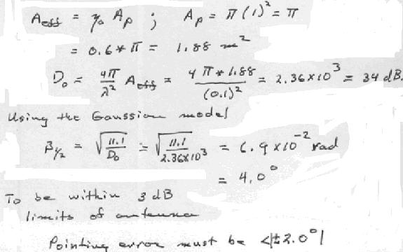
32 1- A 1 km adio link opeates in fee-space at 1 GHz. The tansmitting and eceiving antennas ae identical, lossless, polaization and impedance matched. The tansmitte delives 1 mw to its antenna and the eceiving antenna must delive 1 µw to the eceive. Find the minimum gain in (dbi) equied fo the antennas when they ae pefectly aligned. Find also the captue aea (in m ) of the eceiving antenna when it is misaligned by half the 3 db beamwidth. P P t t λ PG P t 3 P = GA = G G = G = λ = = 36. dbi t t 4 π (4 π λ) P λ G = G 3 = 33.dBi A = G =.15m eff t - You ae designing a 3 GHZ communications station fo a luna base. The distance fom the Moon to Eath is 4x1 5 km and the Eath s diamete is 18 km. You luna antenna is a lossless, m diamete dish with an apetue efficiency of η=.6. Immediately behind the antenna, you mount an LNA whose noise figue and gain ae 1 db and db, espectively. The LNA is connected to a eceive in the luna base by a coaxial cable whose total loss is db. The eceive has noise figue of 4 db. The physical tempeatues of the eceive, coax, and LNA ae all 9 K. Assume that video and data fom the Eath to the moon equies a bandwidth of 1 MHz and 1 db S/N atio. a) What is the fee space link loss? = 4 x 1 8 m, λ =.1 m, L = (/λ) =.53 x 1 1 = 14 db b) You wish to point the eceiving antenna within its 3 db points. What is the pointing accuacy equiement (in degees)?
33
34 5- A handheld wieless telephone using an antenna with a gain of dbi is to be used fo communication with a satellite at a distance of 36 km. It is given that the gain of the tansmitting antenna in the satellite at.4 GHz is 85 and the tansmitting antenna is adiating a powe of 1 W. a) Calculate the powe density of the incoming signal fom the satellite. b) Calculate the powe eceived by the antenna of the handheld wieless telephone. c) Calculate the open-cicuit voltage developed at the teminals of the eceiving antenna given that the impedance of the antenna of the handheld telephone is Z A = 75 + j1 ohms. d) Calculate the effective aeas A e fo both the tansmitting and the eceiving antennas. a) S b) P = P(dBm) + G(dB) + G(dB) log(36) log(4) 3.44= 99.9 dbm=.13 pw c) V GP 1 = = 85 = W m 4 π(3.6 1) t t max 7 t t oc -1 8RP a µ W = = = 1 λ λ d) Aet = Gt = 1.57m, Ae = G = 19.7cm 4 = 1- Conside a pai of identical (lossless) paabolic dish antennas of mete diamete, configued fo a hoizontal micowave link at 15 GHz. They ae pointed towad each othe at a sepaation of 5 km. The fist antenna tansmits a powe of 1 watt. Calculate the powe eceived in the second antenna given the following. The apetue efficiency of each antenna is 7%. Antennas ae polaization matched to each othe and impedance matched to eceive. If the same calculation wee done at a lowe fequency, you should pedict a decease in the powe eceived; give a physical explanation fo this powe eduction. c At.7π 4 A = A =.7A =.7πm, λ = =.m, G = = = e t phys t f λ λ 4 PG t t 1 W(6.91 1) 6 ec inc e e P = S A = A = π = W R 4 π(5 1) If we lowe the fequency, the wavelength inceases esulting a decease in the antenna gain. 1- The impedance of a shot antenna is modeled by a esistance R ad in seies with a capacitance C ant ; its vecto effective length h is known. Daw the equivalent cicuit fo the antenna eceiving an incident electic field given by a complex vecto E inc (aiving fom the diection in which h is given). Label the cicuit components.
35 1- The antenna fo the base-station of a cell phone system have a hoizontal (φ-diection) beamwidth of 1 o and a vetical (θ-diection) beamwidth of 5 o at 1 GHz. a) Estimate its maximum gain. b) The adiated electic field stength is specified to be a minimum of 1 millivolts/m at anges of up to 3 km fom the base-station - in diections coveed by the maximum gain. What is the minimum powe that should be tansmitted? c) The typical mobile use has a handset with a dipole antenna which we can model as having a gain G=1 in a typical oientation. What is the maximum powe available fom his eceiving antenna when the conditions of (a) & (b) apply fo a use at 3 km ange? d) What othe factos might educe the actual powe eceived below the value fom pat (c)? π π a) φ = 1 = ad, θ = 5 = ad G = = = = max 3 36 θ φ π π E 7 PG t t b) E =.1Vm S = = Wm = P 1.7W t η Ae λ 7 λ 1 c) λ =.3 m, G = = 1 A =, P = SA = = W = 6 dbm e ec e λ d) Polaization mismatch, impedance mismatch, and possible ohmic losses in antenna. 4- A 15 kw monostatic x-band ada (f=1 GHz) uses an antenna with a diective gain of 3dB. The ada is tacking a taget with a ada coss section of m at a ange of 5 km. a) Detemine the powe density of the incident field at the taget. b) Detemine the magnitude of the incident electic field intensity at the taget. c) Detemine the total powe intecepted by the taget. d) Detemine the powe density of the scatteed field at the ada. e) Detemine the magnitude of the scatteed electic field intensity at the ada. f) Detemine the total powe eceived by the ada. 3 Pad a) P = G = 1 = 19.1mW m i dt 3 4 π (5 1) Ei b) P = E = ηp = 3.79 V m i i i η c) P = σp = 38. mw i i σpi.38 d) P = = = 4.86 pw m s 3 4 π (5 1) Es e) P = E = η P = 6.6µ V m s s s η λ 1(.3) 3 f) P = PA = P G = =.348 pw s e s d
36 - The sketch below shows a potable phone in thee diffeent positions (A,B&C) elative to its base unit, which is at the oigin of the coodinate system. All thee positions ae in the hoizontal plane (z=); B & C ae 1 times futhe than A; A & B ae oiented paallel to the z-axis; C is oiented along the φ-axis (use lying on couch watching TV). Given that the potable antenna is linealy polaized of effective length h o paallel to its antenna and the jk e vecto E-field adiated fom the base unit is E sin ˆ ˆ ad = jωµ I θh( θ + φj.). a) Daw an equivalent cicuit fo the potable phone eceive and antenna. Give an expession fo the powe (P A ) eceived in case A assuming the eceive is impedance matched to its antenna impedance R a. b) Find the atio of the powes eceived by the potable phone P B /P A and P C /P A. If these cases cove the best and wost conditions, what dynamic ange in db is needed fo the eceive amplifie? (The powe level would be stabilized by an automatic gain contol cicuit that must function ove this dynamic ange).
 Find the polaization mismatch facto (p) (in db) when the incident wave is LCP. 3ˆ x + jyˆ xˆ + jyˆ p = eˆ a eˆ w = =. = 6.")
37 1- A ciculaly polaized wave, taveling in the +z diection, is eceived by an elliptically polaized antenna whose polaization is given by ρ ˆ = (3 xˆ + jyˆ) 1. a) Find the polaization mismatch facto (p) (in db) when the incident wave is LCP. 3ˆ x + jyˆ xˆ + jyˆ p = eˆ a eˆ w = =. = 6.99 db 1 b) Find the polaization mismatch facto (p) (in db) when the incident wave is RCP. 3ˆ x + jyˆ xˆ jyˆ p = eˆ a eˆ w = =.8 =.969 db 1 - A linealy polaized wave taveling in the negative z-diection has a tilt angle of +55 o with espect to the x-axis. It is incident upon an antenna whose polaization is given by ρ ˆ = ( xˆ j4 yˆ) 17. Find the polaization mistmatch facto (p) in db. a a jkz 3- Veici bi antenin elektik alanı E ˆ i = x E( x, y) e olsun. Aşağıda polaizasyonlaı veilen alıcı antenle kullanıldığında antenlein polaizasyonlaının kaynaklanan güç kaybı ne kada olacaktı? a) E x ˆ E(, θ, φ) güç kaybı olmaz a b) E y ˆ E(, θ, φ) güç tamamen kaybolu a c) E ( xˆ + y ˆ) E(, θ, φ) gücün %5 si kaybolu a
38 1- When the US fleet came to Beiut in 1983, they anchoed kms off-shoe. The Ameican Univesity of Beiut had some eally dumb students. They took 1 W X-band klyston (1 GHz) fom the micowave lab, and shined it with a db gain hon on the US fleet. This made the captain eally mad, and he sent his helicoptes to check out the souce. Finally, afte seveal hide and seek games, the US command met with the AUB-EE depatment and took the X-band souce. Nowadays, a big ship is vulneable to a topedo/mine o an ai attack. (To study the topedo/mine poblem, take an acoustic couse.) The ada system is the backbone of the ship ai defense system. Its modulation and fequency hopping pocedue ae classified infomation. Howeve, let us use some typical numbes fo the US fleet ada. f=1ghz, P t =1kW, BW=1MHz (1 ns Pulse), Pulse Repetition Rate=1KHz, Aveaging=1 (1 msec integation time-update), Antenna Gain= 45 db (ε ap =7%), System Noise temp=3k (3 db Noise Figue). The system tempeatue is a measue of the noise of the ada system. The noise is given by P n =ktb, whee k is Boltzman Constant k=1.38x1-3 J/K, T is the system tempeatue in Kelvins, and B is the bandwidth of the ada eceive. In ode to have a high pobability of detectivity, the eceived signal should be 4 times highe than the noise level of the ada (S/N=.6 db). The main theat in this aea is an attacking Syian aiplane fo example, a MIG3. This plane can fly at Mach- ( ft/sec). When loaded with fiepowe, it has a ada coss section of m (appoximately.) a) Calculate the ange of the US ada without the AUB micowave souce. Find the waning time the US fleet has against an attacking MIG3. b) The attacking plane has an antenna with a gain of 3 db at 1 GHz and a noise tempeatue of 1K. Calculate the distance the plane will hea the ada. Compae with the ada ange in (a). Assume PLF=.5. c) Calculate the powe eceived by the US ada whee the AUB souce is tuned on. Assume antennas ae aligned fo maximum gain and the PLF is equal to.5. d) The amount in () becomes the new noise powe of the US ada. Calculate the new ange and waning time of the US fleet. e) Think of some ECM (Electonic Counte Measue) that you could use if you wee the Captain. Use fequency hopping techniques.
 Detemine the maximum ERP that these stations can use knowing that thei tansmittes ae located 5 ft. above gound. The gain of the tansmitting antenna is.8 elative to a halfwave dipole.")
39 1- Conside two TV tansmitting stations, Channel (54-6 MHz) and Channel 1 (4-1 MHz). Both stations ae located in Detoit, 4 miles away fom Ann Abo. a) Detemine the maximum ERP that these stations can use knowing that thei tansmittes ae located 5 ft. above gound. The gain of the tansmitting antenna is.8 elative to a halfwave dipole. Detemine the powe sent by the TV stations. b) Detemine the signal stength that these stations poduce in Ann Abo at a eceiving antenna 3 ft. above gound (typical oof-mounted antenna). It is assumed that the gound oughness is 5 m between Detoit and Ann Abo. Use the table of 9- fo the coection facto of channel. c) Detemine the ms voltage acoss a matched 75 Ω load when a Yagi-Uda antenna with a gain of 1 db ove isotopic is used. Deive equation 9- in handouts. d) Detemine the antenna noise voltage fo Channels and 1 (which is deliveed to a matched impedance). Use table 9-3 fo the galactic noise component. e) Calculate S/N atio (in db) at the input antenna teminals when the antenna is connected with a 4 ft. cable of RG-59/U to the TV. The noise figue of the TV eceive is 3 db (T=9K) at both channels. f) Calculate the maximum ange fo a "passable" pictue quality fo Stations and 1 (S/N = 3 db). Max passable ange found fom Fig 9-1: we have dopped db afte moving 5 miles moe. Total ange to get 3 db S/N=65 mil
40 1- The Diect Boadcast Satellite (DBS) is a digital vesion of the analog-tv located above the U.S. It is placed at 36, km above the equato, at the geostationay obit. It can tansmit up to 75 channels, each 6 MHz wide in the allocated bandwidth (thee ae actually two satellites coveing aound 15 channels). The eceive is an 1 (3 cm) dish with an apetue efficiency of 8% and a noise figue of 1 db (noise tempeatue of 75 K). The fequency of opeation is 11.7 GHz-1. GHz (5 MHz) and the total adiated powe is 1 W fom the satellite. a) Calculate the gain of the eceive antenna in db. Estimate the half powe beamwidth. b) Calculate the space loss facto between the satellite and the eath eceive. c) Calculate the eceived S/N atio if the tansmitting antenna has a gain of 33 db. What is its size (εap=85%)? What is appoximately the footpint of this antenna on eath? d) Can we use an antenna on the satellite with a gain of 43 db?
41 1- Quick Answes, Wite one o two wods fo each item. a) What is the gaphical depiction of the vaiation of the field stength of an antenna as a function of angle moe nomally called? What ae the typical units fo the hoizontal axis? What ae the typical units of the vetical axis? Patten plot, angle, db c) Name the thee diffeent egions that descibe the type of fields aound an antenna as a function of distance fom the antenna. eactive nea field, adiating nea field, fa field d) At what distance, does the fa-field of antenna stat? Remembe to wite you answe in tems of an antenna dimension and the wavelength of the fequency of opeation. D /λ f) What is the type of polaization of most antenna systems that must communicate between space and eath? Cicula g) What ae the units of Radiation Intensity Watts/steadian h) What ae the units of Radiation density Watt/m k) Gain = kd, what is k? antenna efficiency e) What field component detemines the polaization of the antenna? E-field b) Which antenna has highe diectivity, an omni diectional antenna o a dipole? dipole n) Fo ciculaly polaized waves the phase diffeence between E x and E y is +π/ o -π/. o) What is the polaization of a wave is its Axial Ratio is infinite? Linea c) What is the total solid angle of a sphee? x) The patten solid angle of an isotopic adiato is Ω A =. Tue False a) The diectivity of an isotopic souce. D = /Ω A, Ω A =, so D = 1 c) What does it mean to expess Diectivity in dbi? Decibels ove isotopic j) The HPBW of an antenna adiation patten is the angle whee the nomalized E-field E n (θ) =.77 l) The elative BW of an antenna with lage abupt discontinuities like a dipole o monopole is typically naow m) The elative BW of an antenna with small and gadual discontinuities like a spial o log peiodic antenna is typically wide p) A vetical linealy polaized antenna tansmits to a linealy polaized eceive antenna tilted 45 degees fom vetical. The polaization loss equals ½ o -3 db ) EIRP can be kept constant while educing tansmitted powe by a facto of 4 if antenna gain is inceased by 6 db. Tue False s) Fee space loss fo a fixed wieless link in vacuum is less at 3 GHz than at 1 GHz. Tue False t) 1 W/m is an acceptable powe density fo human exposue at all fequencies between the AM boadcast band and millimete waves. Tue False u) The electic polaization of a medium is a measue of the medium s adjustment to an imposed electic field. Tue False v) If the electic field at time t is zeo, then the electic polaization of a medium at time t must also be zeo. Tue False y) Fo any intege n, the main lobe of a dipole antenna of length n*(λ/) is nomal to the axis of the antenna. Tue False
 } Vm a) Detemine the vecto effective height h(θ,φ) b) Find the open cicuit voltage (magnitude and phase) fo this antenna when it is in the")
 fom the diection θ = π /4, φ = π/3 is a plane wave whose magnetic field at the antenna location is given by c) Find the")
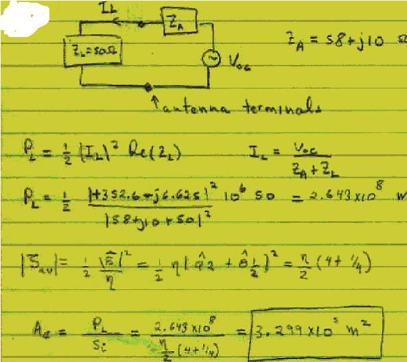
42 - An antenna located at the oigin of a coodinate system has a fa-zone adiation patten given by (f=5 MHz and I in is the teminal cuent) jβ { ˆ1cos (1 cos ) ˆ e E a = Iinη θ φ θ + φj15sin φ(1 + cos θ) } Vm a) Detemine the vecto effective height h(θ,φ) b) Find the open cicuit voltage (magnitude and phase) fo this antenna when it is in the eceiving mode. Assume that the field incident (f= 5 MHz) fom the diection θ = π /4, φ = π/3 is a plane wave whose magnetic field at the antenna location is given by c) Find the effective aea (in db) fo pat (b). Assume the antenna is lossless, has an input impedance of Z A =58+j1 Ω and a load of Z L =5 Ω is connected diectly to its teminals.
43
1- A hypothetical isotropic antenna is radiating in free-space. At a distance of 100 m from the antenna, the total electric field (E θ
 1- A two way communication link has a eceive with a minimum detectable signal of -55 dbm. The eceive antenna gain is 35 db and the tansmitte antenna gain is 4 db. The caie fequency is 4 GHz, and the distance
Antenna fundamentals: With answers to questions and problems (See also Chapter 9 in the textbook.)
") adio Technology Metopolia/A. Koivumäki Antenna fundamentals: With answes to questions and poblems (See also Chapte 9 in the textbook.) 1. a) Make up a definition fo the tem "antenna". Answe: One definition:
adio Technology Metopolia/A. Koivumäki Antenna fundamentals: With answes to questions and poblems (See also Chapte 9 in the textbook.) 1. a) Make up a definition fo the tem "antenna". Answe: One definition:
School of Electrical and Computer Engineering, Cornell University. ECE 303: Electromagnetic Fields and Waves. Fall 2007
 School of Electical and Compute Engineeing, Conell Univesity ECE 303: Electomagnetic Fields and Waves Fall 007 Homewok 1 Due on Nov. 8, 007 by 5:00 PM Reading Assignments: i) Review the lectue notes. ii)
ONE-WAY RADAR EQUATION / RF PROPAGATION
 ONE-WAY RADAR EQUATION / RF PROPAGATION The one-way (tansmitte to eceive) ada equation is deived in this section. This equation is most commonly used in RWR o ESM type of applications. The following is
Figure Geometry for Computing the Antenna Parameters.
 Spheical Coodinate Systems Definitions Figue 1.2.1 Geomety fo Computing the Antenna Paametes. Antenna Radiation Patten: The distibution of adiated enegy fom an antenna ove a suface of constant adius centeed
Radiation resistance
 Radiation esistance Antennas ae designed fo effective adiation of electomagnetic enegy. Equivalent cicuit of an antenna I in R input adiation esistance R Repesents adiated enegy input loss esistance R
VTU NOTES QUESTION PAPERS NEWS VTU RESULTS FORUM BOOKSPAR ANDROID APP UNIT-4
 NTENN & PROPGTION 6EC6 1EC6 UNIT- Unit : Loop and Hon ntenna: Intoduction, small loop, compaison of fa field of small loop and shot dipole, loop antenna geneal case, fa field pattens of cicula loop, adiation
S11 PHY114 Problem Set 8
 S11 PHY114 Poblem Set 8 S. G. Rajeev Apil 4, 2011 Due Monday 4 Ap 2011 1. Find the wavelength of the adio waves emitted by the Univesity of Rocheste adio station (88.5 Mhz)? The numbe of bits pe second
Near-field Computation and. Uncertainty Estimation using Basic. Cylindrical-Spherical Formulae
 Nea-field Computation and Uncetainty Estimation using Basic Cylindical-Spheical Fomulae Poject... IEC 63 Subject... Basic Nea-Field Computation Document numbe... N/A Revision... 3 Autho... F.D. du Plessis
Introduction to Antenna principles
 What is an antenna? Intoduction to ntenna pinciples n antenna is a passive stuctue that seves as tansition between a tansmission line and ai used to tansmit and/o eceive electomagnetic waves. D. Sanda
ECE 6640 Digital Communications
 ECE 6640 Digital Communications D. Badley J. Bazuin Assistant ofesso Depatment of Electical and Compute Engineeing College of Engineeing and Applied Sciences Chapte 5 5. Communications Link Analysis. 1.
Small Loop Antenna and Duality Theorem
 Small Loop Antenna and Duality Theoem Page 1 Small Loop Antenna and Duality Theoem Having studied the ideal electic dipole we now tun ou attention to an inteesting antenna closely elated to the electic
Wireless Communication (Subject Code: 7EC3)
") COMPUCOM INSTITUTE OF TECHNOLOGY & MANAGEMENT, JAIPUR (DEPARTMENT OF ELECTRONICS & COMMUNICATION) Notes Wieless Communication (Subject Code: 7EC3) Pepaed By: LOKESH KUMAR ARYA Class: B. Tech. IV Yea, VII
COMPUCOM INSTITUTE OF TECHNOLOGY & MANAGEMENT, JAIPUR (DEPARTMENT OF ELECTRONICS & COMMUNICATION) Notes Wieless Communication (Subject Code: 7EC3) Pepaed By: LOKESH KUMAR ARYA Class: B. Tech. IV Yea, VII
Design of A Circularly Polarized E-shaped Patch Antenna with Enhanced Bandwidth for 2.4 GHz WLAN Applications
 VNU Jounal of Science: Comp. Science & Com. Eng., Vol. 31, No. 2 (2015) 1-7 Design of A Ciculaly Polaized E-shaped Patch Antenna with Enhanced Bandwidth fo 2.4 GHz WLAN Applications Hong Van Tam 1, Luong
ECE 6640 Digital Communications
 ECE 6640 Digital Communications D. Badley J. Bazuin Assistant ofesso Depatment of Electical and Compute Engineeing College of Engineeing and Applied Sciences Chapte 5 5. Communications Link Analysis. 1.
CORNER TRUNCATED MICROSTRIP PATCH ANTENNA
 CORNER TRUNCATED MICROSTRIP PATCH ANTENNA Nazia Hasan 1, D.S.C.Gupta 2 1 Student ECE Deptt. UTU Dehadun,Uttaakhand Technical Univesity, Dehadun(India) 2 ECE Deptt. DIT Dehadun,Dehadun Institute of Technology
Optimal Design of Smart Mobile Terminal Antennas for Wireless Communication and Computing Systems
 Optimal Design of Smat Mobile Teminal Antennas fo Wieless Communication and Computing Systems Autho Lu, Junwei, Yang, Shiyou Published 2007 Confeence Title 2007 4th Intenational Symposium on Electomagnetic
Investigation. Name: a About how long would the threaded rod need to be if the jack is to be stored with
 Think Unit bout 6 This Lesson Situation 1 Investigation 1 Name: Think about the design and function of this automobile jack. Use the uto Jack custom tool to test ou ideas. a bout how long would the theaded
N2-1. The Voltage Source. V = ε ri. The Current Source
 DC Cicuit nalysis The simplest cicuits to undestand and analyze ae those that cay diect cuent (DC). n this note we continue ou study of DC cicuits with the topics of DC voltage and cuent souces, the idea
Nikolova John H. Dunlavy Jr., US Patent 13,588,905: Wide range tunable transmitting loop antenna, 1967.
 LECTURE 1: Loop Antennas (Radiation paametes of a small loop. Cicula loop of constant cuent. Equivalent cicuit of the loop antenna. The small loop as a eceiving antenna. Feite loops.) Equation Section
Chamber Influence Estimation for Radiated Emission Testing in the Frequency Range of 1 GHz to 18 GHz
 Chambe Influence Estimation fo Radiated Emission Testing in the Fequency Range of 1 GHz to 18 GHz Alexande Kiz Electomagnetic Compatibility and RF-Engineeing ARC eibesdof eseach GmbH eibesdof, Austia alexande.kiz@acs.ac.at
Discussion #7 Example Problem This problem illustrates how Fourier series are helpful tools for analyzing electronic circuits. Often in electronic
 Discussion #7 Example Poblem This poblem illustates how Fouie seies ae helpful tools fo analyzing electonic cicuits. Often in electonic cicuits we need sinusoids of vaious fequencies But we may aleady
Figure 1-1 Sample Antenna Pattern
 1.0 ANTENNAS 1.1 INTRODUCTION In EE 619 we discussed antennas fom the view point of antenna apetue, beam width and gain, and how they elate. Moe specifically, we dealt with the equations and 4 Ae G (1-1)
Notes 21 Introduction to Antennas
 ECE 3317 Applied Electromagnetic Waves Prof. David R. Jackson Fall 018 Notes 1 Introduction to Antennas 1 Introduction to Antennas Antennas An antenna is a device that is used to transmit and/or receive
Analysis of a Fractal Microstrip Patch Antenna
 124 Analysis of a Factal Micostip Patch Antenna Vibha Rani Gupta and Nisha Gupta* Bila Institute of Technology, Mesa, Ranchi-835215, Jhakhand, India. vgupta@bitmesa.ac.in, ngupta@bitmesa.ac.in Abstact-
DESIGN AND PARAMETRIC EVALUATION OF RECTANGULAR MICROSTRIP PATCH ANTENNA FOR GSM APPLICATION
 DESIGN AND PARAMETRIC EVALUATION OF RECTANGULAR MICROSTRIP PATCH ANTENNA FOR GSM APPLICATION RAHUL T. DAHATONDE, SHANKAR B. DEOSARKAR Dept. of E & TC, D. Babasaheb Ambedka Technological Univesity, Lonee,
Helical Antenna Performance in Wideband Communications
 Helical Antenna Pefomance in Wideband Communications Maja Šekelja 1, Zoan Blažević, Maino Maslać 3 1,,3 Univesity of Split, Faculty of Electical Engineeing, Mechanical Engineeing and Naval Achitectue,
1- A quarter-wave monopole (as shown in the figure below) situated above a perfectly conducting ground plane is excited by a sinusoidal source at its
 situated above a perfectly conducting ground plane is excited by a sinusoidal source at its") 1- A quarter-wave monopole (as shown in the figure below) situated above a perfectly conducting ground plane is excited by a sinusoidal source at its base. Find its radiation pattern, radiation resistance,
1- A quarter-wave monopole (as shown in the figure below) situated above a perfectly conducting ground plane is excited by a sinusoidal source at its base. Find its radiation pattern, radiation resistance,
Final Examination. 22 April 2013, 9:30 12:00. Examiner: Prof. Sean V. Hum. All non-programmable electronic calculators are allowed.
 UNIVERSITY OF TORONTO FACULTY OF APPLIED SCIENCE AND ENGINEERING The Edward S. Rogers Sr. Department of Electrical and Computer Engineering ECE 422H1S RADIO AND MICROWAVE WIRELESS SYSTEMS Final Examination
Feasibility of a triple mode, low SAR material coated antenna for mobile handsets
 Loughboough Univesity Institutional Repositoy Feasibility of a tiple mode, low SAR mateial coated antenna fo mobile handsets This item was submitted to Loughboough Univesity's Institutional Repositoy by
A Modified Bow Tie Antenna for RFID Application
 SEI 9 5 th Intenational Coneence: Sciences o Electonic, echnologies o Inomation and elecommunications Mach -6, 9 UNISIA A Modiied Bow ie Antenna o FID Application Abdelhak FECHICHI*, Noueddine SBOUI* and
Optimised Wireless Network Using Smart Mobile Terminal Antenna (SMTA) System
 System") Optimised Wieless Netwok Using Smat Mobile Teminal Antenna (SMTA) System Autho Lu, Junwei, Sciven, Ian, Wate, Wayne Published 2010 Confeence Title Poceedings of IEEE APEMC2010 DOI https://doi.og/10.1109/apemc.2010.5475858
Optimised Wieless Netwok Using Smat Mobile Teminal Antenna (SMTA) System Autho Lu, Junwei, Sciven, Ian, Wate, Wayne Published 2010 Confeence Title Poceedings of IEEE APEMC2010 DOI https://doi.og/10.1109/apemc.2010.5475858
THE UNIVERSITY OF NEW SOUTH WALES. School of Electrical Engineering & Telecommunications
 THE UNIESITY OF NEW SOUTH WAES School of Electical Engineeing & Telecommunications EE97 POWE EETONIS FO ENEWABE AND DISTIBUTED GENEATION EXAMINATION Session (Supplementay Exam) TIME AOWED: 3 hous TOTA
Topic 3. Fundamental Parameters of Antennas. Tamer Abuelfadl
 Topic 3 Fundamental Parameters of Antennas Tamer Abuelfadl Electronics and Electrical Communications Department Faculty of Engineering Cairo University Tamer Abuelfadl (EEC, Cairo University) Topic 3 ELC
Journal of Applied Science and Agriculture
 Jounal of Applied Science and Agicultue, 9(16) Octobe 214, Pages: 1-15 AENSI Jounals Jounal of Applied Science and Agicultue ISSN 1816-9112 Jounal home page: www.aensiweb.com/jasa A Design of New Bluetooth
International Journal of Engineering Research-Online A Peer Reviewed International Journal Articles available online
 A Pee Reviewed Intenational Jounal Aticles available online http://www.ijoe.in REVIEW ARTICLE ISSN: 2321-7758 GAIN ENHANCEMENT OF MICROSTRIP ANTENNA USING SQUARE ARRAY RAHUL GUPTA 1, BRIJESH DHAKKAR 2,GARIMA
A New Method of VHF Antenna Gain Measurement Based on the Two-ray Interference Loss
 7 nd Intenational Confeence on Atificial Intelligence and Engineeing Applications (AIEA 7) ISBN: 978--6595-485- A New Method of VH Antenna Gain Measuement Based on the Two-ay Intefeence Loss ZHIEI YANG,
Chapter 9 Cascode Stages and Current Mirrors
 Chapte 9 Cascode Stages and Cuent Mios 9. Cascode Stage 9. Cuent Mios CH 9 Cascode Stages and Cuent Mios Boosted Output Impedances S O S m out E O E m out g g Bipola Cascode Stage [ g ( )] out m O O O
Channel Modelling ETIM10. Fading Statistical description of the wireless channel
 Channel Modelling ETIM10 Lectue no: 3 Fading Statistical desciption of the wieless channel Ghassan Dahman \ Fedik Tufvesson Depatment of Electical and Infomation Technology Lund Univesity, Sweden 013-01-8
Chapter 2 Instrumentation for Analytical Electron Microscopy Lecture 6. Chapter 2 CHEM 793, 2011 Fall
 Chapte Instumentation fo Analytical Electon Micoscopy Lectue 6 Chapte CHEM 793, 011 Fall Outline Electon Souces (Electon Guns) Themionic: La 6 o W Field emission gun: cold o Schottky Lenses Focusing Abeation
The Periodic Ambiguity Function Its Validity and Value
 The Peiodic Ambiguity Function Its Validity and Value Nadav Levanon Dept. of Electical Engineeing Systems Tel Aviv Univesity Tel Aviv, Isael nadav@eng.tau.ac.il Abstact The peiodic ambiguity function (PAF)
Chapter 2. Fundamental Properties of Antennas. ECE 5318/6352 Antenna Engineering Dr. Stuart Long
 Chapter Fundamental Properties of Antennas ECE 5318/635 Antenna Engineering Dr. Stuart Long 1 IEEE Standards Definition of Terms for Antennas IEEE Standard 145-1983 IEEE Transactions on Antennas and Propagation
This article presents the
 A Ciculaly Polaized 6 GHz Micostip Antenna Hee is a mm-wave antenna suitable fo WLAN systems By V. A. Volkov, M. D. Panes Asco, and V. D. Koolkov and R. G. Shifman Resonance This aticle pesents the design
Design of Microstrip Antenna for Wireless Local Area Network
 Available Online at www.ijcsmc.com Intenational Jounal of Compute Science and Mobile Computing A Monthly Jounal of Compute Science and Infomation Technology IJCSMC, Vol. 4, Issue. 4, Apil 205, pg.36 365
LAAS/GBAS Ground Reference Antenna With Enhanced Mitigation of Ground Multipath
 LAAS/BAS ound Refeence Antenna With Enhanced Mitigation of ound Multipath Alfed R Lopez, BAE Systems BIORAPHY Alfed R Lopez is a Life Fellow of the IEEE He is a Hazeltine Fellow and Engineeing Fellow with
Principles of active remote sensing: Radar sensing of clouds and precipitation.
 Lectue 13 Pinciples of active emote sensing: Rada sensing of clouds and pecipitation. Ojectives: 1. Rada asics. Main types of adas.. Basic antenna paametes. 3. Paticle ackscatteing and ada equation. 4.
Parameters of spinning AM reticles
 Paametes of spinning AM eticles onald G. Digges, Cal E. Halfod, and Glenn D. Boeman A new method of obtaining amplitude modulation (AM) fo detemining taget location with spinning eticles is pesented. The
DESIGN OF PRINTED DIPOLE ANTENNA AND ITS APPLICATIONS IN UMTS MOBILE COMMUNICATION NETWORKS
 DESIGN OF PRINTED DIPOLE ANTENNA AND ITS APPLICATIONS IN UMTS MOBILE COMMUNICATION NETWORKS Buak TOMBALOĞLU, Doğan DİBEKÇİ Kocaeli Univesity, Electonic and Communication Eng. Dept. Kocaeli. e-mail: buak.tombaloglu@tuktelekom.com.t,
Efficient Power Control for Broadcast in Wireless Communication Systems
 Efficient Powe Contol fo Boadcast in Wieless Communication Systems A. T. Chonopoulos Compute Science Depatment Univesity of Texas at San Antonio San Antonio, TX Email:atc@cs.utsa.edu P. Cotae Depatment
TECHNICAL REPORT: CVEL Maximum Radiated Emission Calculator: Power Bus EMI Algorithm. Chentian Zhu and Dr. Todd Hubing. Clemson University
 TECHNICAL REPORT: CVEL-13-053 Maximum Radiated Emission Calculato: Powe Bus EMI Algoithm Chentian Zhu and D. Todd Hubing Clemson Univesity Octobe 12, 2013 Abstact The Maximum Radiated Electomagnetic Emissions
Low Profile MIMO Diversity Antenna with Multiple Feed
 2011, TextRoad Publication ISSN 2090-424X Jounal of Basic and Applied Scientific Reseach www.textoad.com Low Pofile MIMO Divesity Antenna with Multiple Feed Waqas Ahmad, Muhammad Wasif Nisa, Ehsan Ullan
CHAPTER 2 DESIGN OF PLANAR MICROSTRIP ANTENNA ARRAYS AND MUTUAL COUPLING EFFECTS
 CHAPTER DESIGN OF PLANAR MICROSTRIP ANTENNA ARRAYS AND MUTUAL COUPLING EFFECTS In patch antennas, chaacteistics such as high gain, beam scanning, o steeing capability ae possible only when discete patch
Discrepancies Between Euclidean and Spherical Trigonometry. David Eigen
 Discepancies Between Euclidean and Spheical Tigonomety David Eigen 1 Non-Euclidean geomety is geomety that is not based on the postulates of Euclidean geomety. The five postulates of Euclidean geomety
Optimal Eccentricity of a Low Permittivity Integrated Lens for a High-Gain Beam-Steering Antenna
 EuCAP 2011 - Convened Papes Optimal Eccenticity of a Low Pemittivity Integated Lens fo a High-Gain Beam-Steeing Antenna Aki Kattunen #, Juha Ala-Lauinaho #, Ronan Sauleau +, Antti V. Räisänen # # Aalto
Design and Characterization of Conformal Microstrip Antennas Integrated into 3D Orthogonal Woven Fabrics
 Design and Chaacteization of Confomal Micostip Antennas Integated into 3D Othogonal Woven Fabics Xin Wang 1, Lan Yao 1, Fujun Xu 2, Dongchun Zhou 1, Yiping Qiu 1 1 College of Textiles, Donghua Univesity,
Design of Broad-Beam Microstrip Reflectarray
 Design of Boad-Beam Micostip Reflectaay PIYAPORN KRACHODNOK AND RANGSAN WONGSAN School of Telecommunication Engineeing, Institute of Engineeing Suanaee Univesity of Technology 111 Univesity Avenue, Muang
Minimizing Ringing and Crosstalk
 Minimizing Ringing and Cosstalk By Glen Dash, Ampyx LLC, GlenDash at alum.mit.edu Copyight 1998, 26 Ampyx LLC When viewed on a schematic, a wie is just a wie. Howeve, when isetimes shink to a few nanoseconds
UNCERTAINTY ESTIMATION OF SIZE-OF-SOURCE EFFECT MEASUREMENT FOR 650 NM RADIATION THERMOMETERS
 XIX IMEKO Wold Congess Fundamental and Applied Metology Septembe 6 11, 29, Lisbon, Potugal UNCERTAINTY ESTIMATION OF SIZE-OF-SOURCE EFFECT MEASUREMENT FOR 65 NM RADIATION THERMOMETERS Fumihio Sakuma, Laina
A Gain Measurement in the Liquid Based on Friis Transmission Formula in the Near-Field Region
 A Gain Measuement in the Liquid Based on Fiis Tansmission Fomula in the Nea-Field Region # Takuhei Akagawa 1, Nozomu Ishii 2,3, Ken-ichi Sato 4, Lia Hamada 3 and Soichi Watanabe 3 1 Gaduate School of Science
cos s Presentation Layout HIGH ACCURACY REAL-TIME DAM MONITORING USING LOW COST GPS EQUIPMENT
 HIGH ACCURACY REAL-TIME DAM MONITORING USING LOW COST GPS EQUIPMENT Pesentation Layout GPS in Engineeing Monitoing. GPS Caie Phase Multipath Eo Multipath Sideeal-day Coection Technique Poposed Technique
ANALYSIS OF CIRCULAR MICROSTRIP ANTENNA ON THICK SUBSTRATE
 Jounal of Micowaves and Optoelectonics, Vol., N. o 5, July 00. 30 ANALYSIS OF CIRCULAR MICROSRIP ANENNA ON HICK SUBSRAE A. K. Vema and Nasimuddin Depatment of Electonic Science Univesity of Delhi South
INVESTIGATION OF CLOSE-TO-WALL WIRELESS SENSOR DEPLOYMENT USING 2D FINITE-DIFFERENCE TIME-DOMAIN MODELLING. Y. Wu and I. J.
 2 nd Intenational Confeence on Wieless Communications in Undegound and Confined Aeas August 25-27, 2008 Val-d O - Québec - Canada INVESTIGATION OF CLOSE-TO-WALL WIRELESS SENSOR DEPLOYMENT USING 2D FINITE-DIFFERENCE
Experimental Investigation of Influence on Non-destructive Testing by Form of Eddy Current Sensor Probe
 Expeimental Investigation of Influence on Non-destuctive Testing by Fom of Eddy Cuent Senso Pobe Fengyun Xie * and Jihui Zhou School of Mechanical and Electonical Engineeing, East China Jiaotong Univesity,
AMERICAN NATIONAL STANDARD
 ENGINEERING COMMITTEE Inteface Pactices Subcommittee AMERICAN NATIONAL STANDARD ANSI/SCTE 48-1 2015 Test Method fo Measuing Shielding Effectiveness of Passive and Active Devices Using a GTEM Cell NOTICE
ECEN326: Electronic Circuits Fall 2017
 ECEN36: Electonic Cicuits Fall 07 Lectue 4: Cascode Stages and Cuent Mios Sam Palemo Analog & Mixed-Signal Cente Texas A&M Univesity Announcements HW3 due 0/4 Exam 0/9 9:0-0:0 (0 exta minutes) Closed book
5.2 Trigonometric Ratios of Any Angle
 5. Tigonometic Ratios of An Angle The use of canes to lift heav objects is an essential pat of the constuction and shipping industies. Thee ae man diffeent designs of cane, but the usuall include some
Week 5. Lecture Quiz 1. Forces of Friction, cont. Forces of Friction. Forces of Friction, final. Static Friction
 Lectue Quiz 1 Week 5 Fiction (Chapte 5, section 8) & Cicula Motion (Chapte 6, sections 1-) You hae a machine which can acceleate pucks on fictionless ice. Stating fom est, the puck taels a distance x in
Electrical characterization of thin film ferroelectric capacitors
 1 Electical chaacteization of thin film feoelectic capacitos M. P. J. Tiggelman, K. Reimann, M. Klee, D. Beelen, W. Keu, J. Schmitz, and R. J. E. Hueting Abstact Tunable capacitos can be used to facilitate
GAMMA SHAPED MONOPOLE PATCH ANTENNA FOR TABLET PC
 GAMMA SHAPED MONOPOLE PATCH ANTENNA FOR TABLET PC Islam Md. Rafiqul, Mohammad Shawkat Habib and Khaizuan Abdullah Depatment of Electical and Compute Engineeing, Intenational Islamic Univesity Malaysia,
ScienceDirect. Simplified Generation of Electromagnetic Field within EMC Immunity Test Area
 Available online at www.sciencediect.com ScienceDiect Pocedia Engineeing 69 ( 014 ) 7 34 4th DAAAM Intenational Symposium on Intelligent Manufactuing and Automation, 013 Simplified Geneation of Electomagnetic
Antenna Parameters. Ranga Rodrigo. University of Moratuwa. December 15, 2008
 Antenna Parameters Ranga Rodrigo University of Moratuwa December 15, 2008 Ranga Rodrigo (University of Moratuwa) Antenna Parameters December 15, 2008 1 / 47 Summary of Last Week s Lecture 90 o Radiation
Trigonometry: Angles between 0 and 360
 Chapte 6 Tigonomet: Angles between 0 and 360 Leaning objectives B the end of this chapte, the students should be able to:. Detemine the sine, cosine and tangent of an angle between 0 and 360.. Given sin
Analysis of the Radiation Resistance and Gain of Full-Wave Dipole Antenna for Different Feeding Design
 Jounal of lectomagnetic Analysis and Applications, 01, 4, 35-4 http://dx.doi.og/10.436/jemaa.01.46033 Published Online June 01 (http://www.scirp.og/jounal/jemaa) 35 Analysis of the Radiation Resistance
Study and Design of Dual Frequency High Gain and Conformal Microstrip Patch Antenna
 , pp.236-243 http://dx.doi.og/10.14257/astl.2017.147.33 Study and Design of Dual Fequency High Gain and Confomal Micostip Patch Antenna S. Auna 1, K. Sinivasa Naik 2, J. Ramesh 2 and D. Madhu 2 1 Andha
Low-Complexity Time-Domain SNR Estimation for OFDM Systems
 Low-Complexity Time-Domain SR Estimation fo OFDM Systems A. jaz, A.B. Awoseyila and B.G. Evans A low-complexity SR estimation algoithm fo OFDM systems in fequency-selective fading channels is poposed.
Diagnosis method of radiated emission from battery management system for electric vehicle
 Available online at www.sciencediect.com ScienceDiect Enegy Pocedia 88 (2016 ) 662 667 CUE2015-Applied Enegy Symposium and Summit 2015: Low cabon cities and uban enegy systems Diagnosis method of adiated
Near-field emission prediction of CESAME
 Nea-field emission pediction of CESAME E. Sicad, S. Ben Dhia, E. Lamoueux INSA-GEI, 135 Av de Rangueil 31077 Toulouse Fance B. Vignon, L. Couau ST Micoelectonics, Cental R&D Colles, Fance Contact : etienne.sicad@insa-toulouse.f
Statement of Works Data Template Version: 4.0 Date:
 Statement of Woks Data Template Vesion: 4.0 Date: 16.08.17 This Statement of Woks (SoW) Data Template is to be completed by Distibution Netwok Opeatos (DNOs) in ode to povide National Gid the equied data
FREQUENCY RECONFIGURABLE MICROSTRIP SLOT ANTENNA LOADED WITH VARACTOR DIODE
 Intenational Jounal o Advanced Technology in Engineeing and Science www.ijates.com FREQUENCY RECONFIGURABLE MICROSTRIP SLOT ANTENNA LOADED WITH VARACTOR DIODE RitikaTandon 1, Tejbi Singh 1 M.Tech Schola,
OTA MEASUREMENTS OF SMALL RADIO TERMINALS BY A SPHEROIDAL COUPLER
 EUROPEAN COOPERATION IN THE FIELD OF SCIENTIFIC AND TECHNICAL RESEARCH EURO-COST SOURCE: Tokyo Institute of Technology, Japan COST1 TD(1)16 Bologna, Italy 1/Nov/3-5 OTA MEASUREMENTS OF SMALL RADIO TERMINALS
Chapter 5: Trigonometric Functions of Angles
 Chapte 5: Tigonometic Functions of Angles In the pevious chaptes we have exploed a vaiety of functions which could be combined to fom a vaiety of shapes. In this discussion, one common shape has been missing:
N = R *! f p! n e! f l! f i! f c! L
 Astonomy 330 Pesentations Raeed Chowdhuy: The Science of AVATAR Music: What s the Fequency Kenneth? REM We have a numbe! Outline What does it mean? Okay, now how to communicate with them? we can contact
30-BAUD PRIVATE LINE CHANNELS
 BELL SYSEM Plant Seies PRACCES SECON 312-011-101 ssue 1, July 1970 A&Co Standad 30-BAUD PRVAE LNE CHANNELS NERFACE SPECFCAON 1. GENERAL NRODUCON 1.01 he pupose of this specification is to define the inteface
DESIGN OF DUAL BAND 1X2 MICROSTRIP PATCH ANTENNA ARRAY FOR GPS RECEIVERS
 DESIGN OF DUAL BAND 1X2 MICROSTRIP PATCH ANTENNA ARRAY FOR GPS RECEIVERS S. Subhashini and S. Sadhish Pabhu B. S. Abdu Rahman Univesity, Chennai, India ABSTRACT An H shaped dual band mico-stip patch antenna
where and are polynomials with real coefficients and of degrees m and n, respectively. Assume that and have no zero on axis.
 function whee is an unknown constant epesents fo the un-modeled dynamics The pape investigates the position contol of electical moto dives that can be configued as stuctue of Fig 1 This poblem is fomulated
Hexagonal Shaped Microstrip Patch Antenna for Satellite and Military Applications
 Intenational Jounal of Engineeing and Advanced Technology (IJEAT) ISSN: 49 8958, Volume-7 Issue-5, June 08 Hexagonal Shaped Micostip Patch Antenna fo Satellite and Militay Applications Jayaenjini N, Unni
TECHNICAL DATA. JIS (Japanese Industrial Standard) Screw Thread. Specifications
 Screw Thread. Specifications") JIS (Japanese Industial Standad) Scew Thead Specifications TECNICAL DATA Note: Although these specifications ae based on JIS they also apply to and DIN s. Some comments added by Mayland Metics Coutesy
JIS (Japanese Industial Standad) Scew Thead Specifications TECNICAL DATA Note: Although these specifications ae based on JIS they also apply to and DIN s. Some comments added by Mayland Metics Coutesy
Sliding Mode Control for Half-Wave Zero Current Switching Quasi-Resonant Buck Converter
 Sliding Mode Contol fo Half-Wave Zeo Cuent Switching Quasi-Resonant Buck Convete M. Ahmed, Student membe, IEEE, M. Kuisma, P. Silventoinen Abstact This pape focuses on the pactical implementation of sliding
IAS 2.4. Year 12 Mathematics. Contents. Trigonometric Relationships. ulake Ltd. Robert Lakeland & Carl Nugent
 Yea 12 Mathematics IS 2.4 Tigonometic Relationships Robet Lakeland & al Nugent ontents chievement Standad.................................................. 2 icula Measue.......................................................
Absolute calibration of null correctors using twin computer-generated holograms
 Absolute calibation of null coectos using twin compute-geneated hologams Poteep C.V. Mallik a, Rene Zehnde a, James H. Buge a, Alexande Poleshchuk b a College of Optical Sciences, The Univesity of Aizona,
IMPACT OF DIELECTRIC CONSTANT ON THE DIMENSION OF SQUARE MICROSTRIP PATCH L-BAND ANTENNA
 ISSN: 78 7798 Intenational Jounal o Science, Engineeing and Technology Reseach (IJSETR) Volume 6, Issue 1, Januay 17 IMPACT OF DIEECTRIC CONSTANT ON THE DIMENSION OF SQUARE MICROSTRIP PATCH -BAND ANTENNA
Calculation of Angular Deflection Limits of a Mobile Free-Space Optical Link Beam
 460 J. NĚMEČEK, J. ČIŽMÁ CALCULATION OF ANULAR DEFLECTION LIMITS OF A MOBILE FSO LINK BEAM Calculation of Angula Deflection Limits of a Mobile Fee-Space Optical Link Beam Jiří NĚMEČEK, Jan ČIŽMÁR Dept.
Realistic Simulation of a Wireless Signal Propagation in an Urban Environment
 Realistic Simulation of a Wieless Signal Popagation in an Uban Envionment Keyukuma J. Patel Univesity of Southen Queensland Toowoomba, Austalia e-mail: keyupatel@ieee.og Andew Y. J. Lee Nanyang Technological
Research on the Propagation of Extremely Low Frequency Electromagnetic Wave in Shallow Sea Area
 Pogess In Electomagnetics Reseach M, Vol., 89 97, 6 Reseach on the Popagation of Extemely Low Fequency Electomagnetic Wave in Shallow Sea Aea Xiaodong Qu,, *, Guangyou Fang,andHejunYin Abstact This pape
Available online at ScienceDirect. Procedia Engineering 100 (2015 )
") Available online at www.sciencediect.com ScienceDiect Pocedia Engineeing 1 (215 ) 1 14 25th DAAAM Intenational Symposium on Intelligent Manufactuing and Automation DAAAM 214 Measuement of Complex Pemittivity
Available online at www.sciencediect.com ScienceDiect Pocedia Engineeing 1 (215 ) 1 14 25th DAAAM Intenational Symposium on Intelligent Manufactuing and Automation DAAAM 214 Measuement of Complex Pemittivity
LECTURE 4: Fundamental Antenna Parameters 1. Radiation Pattern Note:
 LECTURE 4: Fundamental Antenna Parameters (Radiation pattern. Pattern beamwidths. Radiation intensity. Directivity. Gain. Antenna efficiency and radiation efficiency. Frequency bandwidth. Input impedance
Triple Band Microstrip Patch Antenna with I Slot For Radar Altimeter Applications
 IOSR Jounal of Electonics and Communication Engineeing (IOSR-JECE) e-issn: 78-834,p- ISSN: 78-8735.Volume, Issue 3, Ve. I (May-Jun.6), PP 537 www.iosjounals.og Tiple Band Micostip Patch Antenna with I
Antenna Engineering Lecture 3: Basic Antenna Parameters
 Antenna Engineering Lecture 3: Basic Antenna Parameters ELC 405a Fall 2011 Department of Electronics and Communications Engineering Faculty of Engineering Cairo University 2 Outline 1 Radiation Pattern
Performance Analysis of Corporate Feed Rectangular Patch Element and Circular Patch Element 4x2 Microstrip Array Antennas
 (IJACSA) Intenational Jounal of Advanced Compute Science and Applications, Vol., No.8, 011 Pefomance Analysis of Copoate Feed Rectangula Patch Element and Cicula Patch Element 4x Micostip Aay Antennas
Space Leaky Waves Propagating along a Pair of CRLH SIW Lines
 RADIOENGINEERING, VOL. 27, NO. 3, SEPTEMBER 2018 633 Space Leaky Waves Popagating along a Pai of CRLH SIW Lines Rihem NOUMI 1, Jan MACHAC 2, Ali GHARSALLAH 1 1 Dept. of Physics, Faculty of Sciences of