CMSC838. Tangible Interactive Assistant Professor Computer Science
|
|
|
- Janis Terry
- 5 years ago
- Views:
Transcription


1 CMSC838 Tangible Interactive Computing Week 04 Lecture 05 Feb 17, 2014 Electronic Components Sensing and Sensors Human Computer Interaction Assistant Professor Computer Science
2 Inspiration
3 [source:

4 [source: Nathan Brunstein, This one is concept only

5 [source: Nathan Brunstein, This one is concept only
6 oday s lass
7 Today 1. MPA01 Chat / Pitches 2. Intro to Electricity Concepts 3. Wires 4. Switches and Voltage Dividers 5. Resistive Sensing

8

9
10 You have to make a new type of physical input for a computer using an Arduino. You do not have to make a custom application to demonstrate said input but this is highly recommended.

11 [source:

12 [source:

13
14 ommon components: ires
15
16 WIRE TYPES This wire is useful for wiring breadboards; the solidcore ends slip easily into breadboard sockets and will not fray in the process. However, these wires have the tendency to snap after a number of flexes Comprised of a number of individual strands of copper. Better conductor than solid-core wire because the individual wires together comprise a greater surface area. Also, stranded wire will not break easily when flexed. Made up of a number of individual strands of wire braided together. Like stranded wires, better conductors than solid-core wires, and will not break easily when flexed. Often used as an electromagnetic shield in noisereduction Cables. [source: Chapter 3 of Scherz & Monk, Practical Electronics, 3 rd Edition, 2013]
17
18 22 AWG solid core wire
19 American wire gauge (AWG) is a standardized wire gauge system used since 1857 predominantly in the United States and Canada for the diameters of round, solid, nonferrous, electrically conducting wire. The cross-sectional area of each gauge is an important factor for determining its current-carrying capacity.
20 AWG Gauge AWG Gauge vs. Wire Diameter (mm) Wire Diameter (mm) [source: Chapter 3 of Scherz & Monk, Practical Electronics, 3 rd Edition, 2013]
21 AWG Gauge AWG Gauge vs. Wire Diameter (mm) Yes, AWG gauge number is counter intuitive. As the wire diameter gets big, the wire gauge gets small! Wire Diameter (mm) [source: Chapter 3 of Scherz & Monk, Practical Electronics, 3 rd Edition, 2013]
 35 30 25 20. 40 AWG Wire. 15 10.")
 [source: Chapter 3 of Scherz & Monk,")
22 AWG Gauge AWG Gauge vs. Wire Diameter (mm) AWG Wire AWG Wire AWG Wire Wire Diameter (mm) [source: Chapter 3 of Scherz & Monk, Practical Electronics, 3 rd Edition, 2013]
 Resistance: R = ρ A A piece of resistive material with electrical contacts on both")
. [source: http://en.wikipedia.")
23 RESISTANCE R Resistance is the opposition to the flow of electric current. It is measured in the SI derived unit ohm (symbol: Ω) Resistance: R = ρ A A piece of resistive material with electrical contacts on both ends. ρ is the electrical resistivity of the material measured in ohms-meters is the length of the piece of material (measured in meters, m) A is the cross-sectional area of the material (measured in square meters, m 2 ). [source:
24 Ohms/km The Relationship Between Wire Diameter (mm) and Resistance (Ohms/km) Wire Diameter (mm) [source: Chapter 3 of Scherz & Monk, Practical Electronics, 3 rd Edition, 2013]
25 Ohms/km The Relationship Between Wire Diameter (mm) and Resistance (Ohms/km) AWG Wire Wire Diameter (mm) [source: Chapter 3 of Scherz & Monk, Practical Electronics, 3 rd Edition, 2013]
26 Ohms/km Current Carrying Capacity (A) The Relationship Between Wire Diameter (mm) and Resistance and Current Carrying Capacity (A) Ohms per km Current Carrying Capacity (A) Wire Diameter (mm) 0 [source: Chapter 3 of Scherz & Monk, Practical Electronics, 3 rd Edition, 2013]
27 Ohms/km Current Carrying Capacity (A) The Relationship Between Wire Diameter (mm) and Resistance and Current Carrying Capacity (A) If too much current is sent through a large-gauge (smalldiameter) wire, the wire could become hot enough to melt! Ohms per km Current Carrying Capacity (A) Wire Diameter (mm) 0 [source: Chapter 3 of Scherz & Monk, Practical Electronics, 3 rd Edition, 2013]
28 ommon components: witches


29 SWITCHES There is an enormous variety of switches from toggle to rotary to DIP to push-button to DIP to rocker. Switches differ in how they are actuated and how many circuits they can control
30 WHAT IS A SWITCH? A circuit diagram with an LED, resistor, and a switch. When the switch is closed, current flows and the LED can illuminate. Otherwise no current flows, and the LED receives no power. [source:

 Maintained: Stay")
 [source:")
31 SWITCHES Momentary vs. Maintained Momentary: remain active only as long as they are actuated (e.g., keys on a keyboard, buttons) Maintained: Stay in one state until actuated into a new one (e.g., light switches, DIP switches) [source:

32 SWITCHES Arduino Pro 328 The Arduino Pro has two SMD switches: a slide switch for power control, and a pushbutton for reset control. [source:
33 SWITCHES & MCU Hooking up a button to Arduino When the button is open, this input pin is in an unknown state ( floating ), that is bad! With this configuration, when the button closes, the MCU would read LOW from the input pin, but what about when the button is open? [source:
34 SWITCHES & MCU Hooking up a button to Arduino Add VCC to remove this float ambiguity and pull the input pin to HIGH when the button is open. Now, we ve added VCC to pull the input pin to HIGH, but what happens to the circuit when the button closes? [source:
35 SWITCHES & MCU Hooking up a button to Arduino Add VCC to remove this float ambiguity and pull the input pin to HIGH when the button is open. When the button closes, this creates a short circuit! All of the current will flow directly from VCC to GND this is bad! [source:
36 SHORT CIRCUIT Short circuits are never good and should always be avoided When the button closes, this creates a short circuit! All of the current will flow directly from VCC to GND this is bad! Recall Ohm s law, I = V/R. In this case, the circuit has no resistance, so the current is infinite (or will try to be). This could cause your wires to burn up, damage the power supply, drain your battery, etc. [source:
37 SWITCHES & MCU Hooking up a button to Arduino This resistor is a pull-up resistor, required to bias the input high. Without it, when the switch closes, the circuit would short to ground! Now, when the switch is open, the MCU pin is connected through the resistor to 5V (HIGH). When the switch is closed, the pin is tied directly to GND (LOW). [source:
38 SWITCHES & MCU Hooking up a button to Arduino If you choose a low resistor for R1, more current flows to GND but the more power is wasted when the button is hit. In contrast, a high R1 value (e.g., 4MΩ) might not work as a pull-up A low resistor value is called a strong pull-up (more current flows), a high resistor value is called a weak pull-up (less current flows). [source:
39 SWITCHES & MCU Hooking up a button to Arduino This resistor is a pull-up resistor, required to bias the input high. Without it, when the switch closes, the circuit would short to ground! The question then becomes, what resistor value should you select? Now, when the switch is open, the MCU pin is connected through the resistor to 5V (HIGH). When the switch is closed, the pin is tied directly to GND (LOW). [source:
40 SELECT A PULL-UP RESISTOR What should R1 be? The value of the pull-up resistor needs to be chosen to satisfy two conditions: 1. When the button is pressed, the input pin is pulled low. The value of resistor R1 controls how much current you want to flow from VCC, through the button, and then to ground. 2. When the button is not pressed, the input pin is pulled high. The value of the pull-up resistor controls the voltage on the input pin. A very small amount of current flows from VCC through R1 and into the input pin. How small? This depends on the value of R1 and the resistance of the input pin in the MCU. [source:
41 To satisfy these conditions, we have to look inside the MCU
42 SWITCHES & MCU Hooking up a button to Arduino Input pins on MCUs tend to have high resistances of 1k-1MΩ In reality, the MCU has an internal resistor. So the pull-up resistor (R1) and the internal MCU resistor (R2) form a voltage divider [source:
43 VOLTAGE DIVIDER Hooking up a button to Arduino V in If R 1 =R 2, then: V out In reality, the MCU has an internal resistor. So the pull-up resistor (R1) and the internal MCU resistor (R2) form a voltage divider [source:
44 VOLTAGE DIVIDER Hooking up a button to Arduino V in If R 1 =R 2, then: V out In reality, the MCU has an internal resistor. So the pull-up resistor (R1) and the internal MCU resistor (R2) form a voltage divider [source:
45 VOLTAGE DIVIDER Hooking up a button to Arduino 6 V out for varying values of R1 with R2 fixed at 1MΩ V in 5 4 V out V out E+10 If R 1 =R 2, then: R1 Value in kohms (Log Scale) [source:
46 VOLTAGE DIVIDER Hooking up a button to Arduino 6 V out for varying values of R1 with R2 fixed at 1MΩ V in 5 4 V out V out E+10 If R 1 =R 2, then: R1 Value in kohms (Log Scale) [source:

47 ARDUINO BUILT-IN PULL-UP Because pull-up resistors are so commonly needed, many MCUs like the ATmega328 on Arduino, have internal pull-ups that can be enabled or disabled

48
49 Let s look at some buttons and switches!
50
51
52

53 TACTILE BUTTON ASSORTMENT Perhaps surprisingly, this button has four connections, you would probably only expect two how come? [source:

54 [source:

55
56 TACTILE BUTTON ASSORTMENT This button has four connections! You would probably only expect two. You can see that connections (1) and (2) are connected together and connections (3) and (4) are connected together [source:
57 TACTILE BUTTON ASSORTMENT If you pick up a button and you re confused or you can t find the datasheet, use continuity testing on your multimeter first without the button pressed and then with the switch pressed [source:

58

59


60 MICROSWITCH Microswitches are not designed to be pressed directly but are often used for things like a microwave door to detect that the door is closed or as an anti-tamper switch. [source: Chapter 3, Simon Monk, Hacking Electronics, 2013]
 C (N.C.) [source: http://en.")
61 MICROSWITCH A microswitch is a double throw or change-over switch. There is one common connection C that switches between B and C depending on the actuation state. C B (N.O.) C (N.C.) [source:


62 TOGGLE SWITCHES If you look in a component catalog (e.g., Digikey), you will find a bewildering number of toggle switches with names like DPDT, SPDT, SPST, SPST, etc. Single-Pole, Single-Throw Single-Pole, Double-Throw Double-Pole, Double-Throw D = Double S = Single P = Pole T = Throw [source: Chapter 3, Simon Monk, Hacking Electronics, 2013]


 in the")

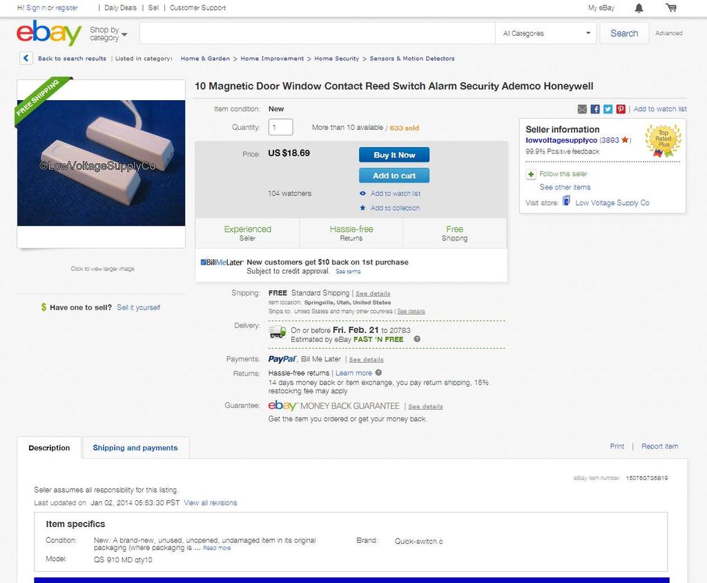
63 REED SWITCH An electrical switch operated by an applied magnetic field; it consists of a pair of contacts on ferrous metal reeds in a hermetically sealed glass envelope. The contacts close (or open) in the presence of a magnetic field [source:

64 REED SWITCH [source:
65 REED SWITCH Uninsulated Reed Switch: $1.50 Insulated Reed Switch: $ [source:
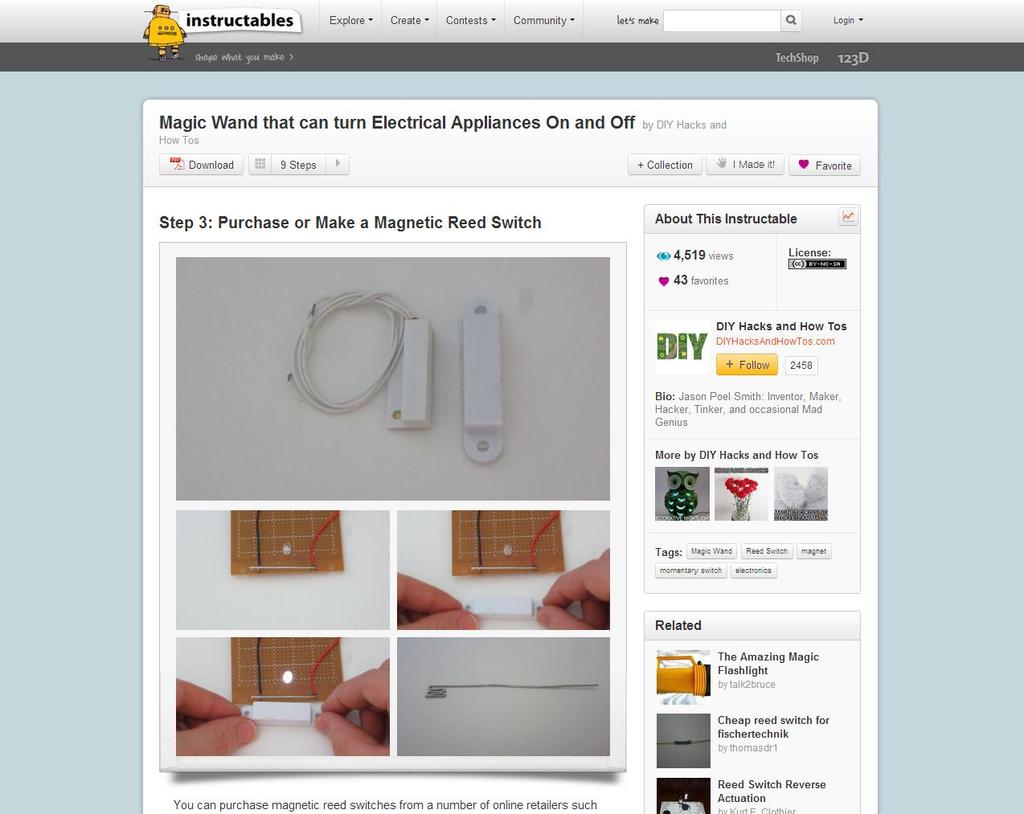
66 How are reed switches used?

67
68
69

70


71


72 HALL EFFECT SENSOR A Hall effect sensor is a transducer that varies its output voltage in response to a magnetic field. Unlike the reed switch, no moving parts! Can be used for tracking position, speed, and proximity. Hall Effect Sensor: $ Three types: Hall Effect Switch, Hall Effect Latch, Hall Effect Ratiometric; [source:

73
74 SENSING THE PHYSICAL WORLD Touch Light Sound Distance Force Movement Temperature Magnetic Fields Vibration

; $1.")

75 READING RESISTIVE SENSORS Many sensors are resistive sensors, which change their resistance based on some stimulus. Thermistor 4.7k; $0.95* Touch Membrane Potentiometer; $12.95 Photocell (or photodetector or photo resistor); $1.50 Thermistor 10k; $0.75 Force Resistive Sensor 0.5 ; $6.95 Flex Sensor 4.5 ; $12.95 *Note: Prices are from Sparkfun.com; parts are cheaper in bulk and often cheaper from Digikey.com [source: Sparkfun.com]
76 Typically, to use these guys, we need our friend:

77 Typically, to use these guys, we need our friend: Because MCUs with analog-to-digital converters can measure voltages easily but not resistances
78 VOLTAGE DIVIDER You ll see it written in a number of ways We used this schematic before [source:
79 VOLTAGE DIVIDER You ll see it written in a number of ways: We used this schematic before There s also these But no matter what, this equation works: If R 1 =R 2, then: [source:
80 VOLTAGE DIVIDER EXAMPLE Recall our friend: We want to use this photoresistor: Schematic now looks like this: [source:
81 VOLTAGE DIVIDER EXAMPLE Why even do a voltage divider? Why can t we just do this? Or this
82 OK, back to our example
83 VOLTAGE DIVIDER EXAMPLE Let s assume the photocell resistance varies from 1kΩ in the light to 10kΩ in the dark. We want to pick R1 that maximizes our V out range. Schematic now looks like this: [source:
84 V out Range VOLTAGE DIVIDER EXAMPLE Let s assume the photocell resistance varies from 1kΩ in the light to 10kΩ in the dark. We want to pick R1 that maximizes our V out range R1 Value (in kω)
85

86 Some book sources
Unit 1 Electronics Name: Form:
 Unit 1 Electronics Name: Form: Electronics Electronics is the study of components and techniques used to be able to build circuits controlled by electricity. An electronic system uses discrete components.
Smart Garment Design
 Smart Garment Design 5. Basic Electronics Sungmin Kim SEOUL NATIONAL UNIVERSITY Definition of Circuit A closed loop of electricity that contains a power source and a load Components Power source Something
User Interface Engineering FS 2013
 User Interface Engineering FS 2013 Input Fundamentals 23.09.2013 1 Last Week Brief Overview of HCI as a discipline History of the UI Product perspective Research perspective Overview of own research as
Switches. Resources and methods for learning about these subjects (list a few here, in preparation for your research):
:") Switches This worksheet and all related files are licensed under the Creative Commons Attribution License, version 1.0. To view a copy of this license, visit http://creativecommons.org/licenses/by/1.0/,
Switches This worksheet and all related files are licensed under the Creative Commons Attribution License, version 1.0. To view a copy of this license, visit http://creativecommons.org/licenses/by/1.0/,
THE INPUTS ON THE ARDUINO READ VOLTAGE. ALL INPUTS NEED TO BE THOUGHT OF IN TERMS OF VOLTAGE DIFFERENTIALS.
 INPUT THE INPUTS ON THE ARDUINO READ VOLTAGE. ALL INPUTS NEED TO BE THOUGHT OF IN TERMS OF VOLTAGE DIFFERENTIALS. THE ANALOG INPUTS CONVERT VOLTAGE LEVELS TO A NUMERICAL VALUE. PULL-UP (OR DOWN) RESISTOR
ENGR 40M Project 2a: Useless box
 ENGR 40M Project 2a: Useless box Prelab due 24 hours before your section, April 16 19, 2018 Lab due before your section, April 24 27, 2018 1 Objectives In this lab, you ll assemble a useless box like the
Workshop 9: First steps in electronics
 King s Maths School Robotics Club Workshop 9: First steps in electronics 1 Getting Started Make sure you have everything you need to complete this lab: Arduino for power supply breadboard black, red and
Laboratory Exercise Nine
 Basic D.C. AVIM 121 Lab 9 Page 1 of 7 rev. 08.09 Laboratory Exercise Nine Objectives Construct a circuit from a schematic Use SPDT, SPST and DPDT switches Learn how to control a load with several switches
EE Laboratory 4 - First Order Circuits *** Due in recitation on the week of June 2-6, 2008 ***
 Page 1 EE 15 - - First Order Circuits *** Due in recitation on the week of June -6, 008 *** Authors R.D. Christie Objectives At the end of this lab, you will be able to: Confirm the steady state model
Intro to Electronics. Week 1
 Intro to Electronics Week 1 1 What is included? DIY ELECTRONICS 2 Lights http://www.flickr.com/photos/oskay/3423822454/ Intro to Electronics, Week 1 Last modified April 16, 2012 3 Sounds http://www.flickr.com/photos/createdigitalmedia/3701158293/
DET: Technological Studies Applied Electronics Intermediate 2
 DET: Technological Studies Applied Electronics Intermediate 2 4597 Spring 1999 HIGHER STILL DET: Technological Studies Applied Electronics Intermediate 2 Support Materials *+,-./ CONTENTS Teacher s guide
Resistive components in circuits
 Resistive components in circuits Learners should be able to: (a) describe the effect of adding resistors in series and (b) use equations for series and parallel resistor combinations resistors in series
// Parts of a Multimeter
 Using a Multimeter // Parts of a Multimeter Often you will have to use a multimeter for troubleshooting a circuit, testing components, materials or the occasional worksheet. This section will cover how
Introduction to Electronics and Breadboarding Circuits
 Introduction to Electronics and Breadboarding Circuits What we're going to learn today: What is an electronic circuit? What kind of power is needed for these projects? What are the fundamental principles
Voltage Dividers a learn.sparkfun.com tutorial
 Voltage Dividers a learn.sparkfun.com tutorial Available online at: http://sfe.io/t44 Contents Introduction Ideal Voltage Divider Applications Extra Credit: Proof Resources and Going Further Introduction
Cornerstone Electronics Technology and Robotics I Week 19 Electrical Relays
 Cornerstone Electronics Technology and Robotics I Week 19 Electrical Relays Administration: o Prayer o Turn in quiz o Review voltage regulators: Review SPST, SPDT, DPST, DPDT switches http://cornerstonerobotics.org/curriculum/lessons_year1/er%20week8,%
Resistance and Ohm s law
 Resistance and Ohm s law Objectives Characterize materials as conductors or insulators based on their electrical properties. State and apply Ohm s law to calculate current, voltage or resistance in an
Sensor Comparator. Fiendish objects
 Part α: Building a simple Sensor Comparator : Step 1: Locate the following circuit parts from your bag. Part Number Fiendish objects Part name 1 Wire Kit: Contains wires. 3 10kΩ Resistor 9 Photodetector
Embedded Control. Week 1 (6/29/11)
") Embedded Control Week 1 (6/29/11) Week 1 15:00 Lecture Circuit theory, terminology Overview of elementary circuit components Reading circuit diagrams 16:00 Lab NXT GPIO with HiTechnic sensor expansion
Embedded Control Week 1 (6/29/11) Week 1 15:00 Lecture Circuit theory, terminology Overview of elementary circuit components Reading circuit diagrams 16:00 Lab NXT GPIO with HiTechnic sensor expansion
Design and Technology
 E.M.F, Voltage and P.D E.M F This stands for Electromotive Force (e.m.f) A battery provides Electromotive Force An e.m.f can make an electric current flow around a circuit E.m.f is measured in volts (v).
introduction to Digital Electronics Install the Arduino IDE on your laptop if you haven t already!
 introduction to Digital Electronics Install the Arduino IDE 1.8.5 on your laptop if you haven t already! Electronics can add interactivity! Any sufficiently advanced technology is indistinguishable from
ENVIRONMENTAL. Operating Temperature: -40ºC to +130ºC. Wire Size. Code Accepted Max Wire Gauge Insulation AWG Solid or Stranded
 Wire-to-Wire (WTW) connectors have been used in the industrial market for years with traditional 2-Piece (plug & socket) connector systems. These require crimp and poke wire terminations to connect discrete
Attribution Thank you to Arduino and SparkFun for open source access to reference materials.
 Attribution Thank you to Arduino and SparkFun for open source access to reference materials. Contents Parts Reference... 1 Installing Arduino... 7 Unit 1: LEDs, Resistors, & Buttons... 7 1.1 Blink (Hello
CMSC838. Tangible Interactive Assistant Professor Computer Science. Week 11 Lecture 20 April 9, 2015 Motors
 CMSC838 Tangible Interactive Computing Week 11 Lecture 20 April 9, 2015 Motors Human Computer Interaction Laboratory @jonfroehlich Assistant Professor Computer Science TODAY S LEARNING GOALS 1. Learn about
The Art of Electrical Measurements
 The Art of Electrical Measurements Purpose: Introduce fundamental electrical test and measurement tools and the art of making electrical measurements. Equipment Required Prelab 1 Digital Multimeter 1 -
Physics 3330 Experiment #2 Fall DC techniques, dividers, and bridges
 Physics 3330 Experiment #2 Fall 2002 DC techniques, dividers, and bridges Purpose You will gain a familiarity with the circuit board and work with a variety of DC techniques, including voltage dividers,
Basic Microprocessor Interfacing Trainer Lab Manual
 Basic Microprocessor Interfacing Trainer Lab Manual Control Inputs Microprocessor Data Inputs ff Control Unit '0' Datapath MUX Nextstate Logic State Memory Register Output Logic Control Signals ALU ff
LAB 1 AN EXAMPLE MECHATRONIC SYSTEM: THE FURBY
 LAB 1 AN EXAMPLE MECHATRONIC SYSTEM: THE FURBY Objectives Preparation Tools To see the inner workings of a commercial mechatronic system and to construct a simple manual motor speed controller and current
Construction of a high-voltage Buck-Boost capacitor charger. Transformer and logic
 Construction of a high-voltage Buck-Boost capacitor charger This paper describes the construction of the circuit described in the paper titled A high-voltage Buck- Boost capacitor charger. As described
The Discussion of this exercise covers the following points:
 Exercise 5 Resistance and Ohm s Law EXERCISE OBJECTIVE When you have completed this exercise, you will be familiar with the notion of resistance, and know how to measure this parameter using an ohmmeter.
ELEXBO. Electrical - Experimentation Box
 ELEXBO Electrical - Experimentation Box 1 Table of contents 2 Introduction...3 Basics...3 The current......4 The voltage...6 The resistance....9 Measuring resistance...10 Summary of the electrical values...11
Block Diagram of a DC Power Supply. Wiring diagrams are used to help with the actual circuit wiring.
 Electronics Technology and Robotics I Week 3 Schematics, Conductors, and Insulators Administration: o Prayer o Review measuring voltage, current, and resistance w/ DMM Electrical Diagrams: o Schematic
Application Note CDIAN003
 Application Note CDIAN003 CDI GaN Bias Board User s Guide Revision 4.0 February 20, 2015 Quick Start Guide Shown below are the essential connections, controls, and indicators for the GaN Bias Control Board.
Workshop Part Identification Lecture N I A G A R A C O L L E G E T E C H N O L O G Y D E P T.
 Workshop Part Identification Lecture N I A G A R A C O L L E G E T E C H N O L O G Y D E P T. Identifying Resistors Resistors can be either fixed or variable. The variable kind are called potentiometers
Lab# 13: Introduction to the Digital Logic
 Lab# 13: Introduction to the Digital Logic Revision: October 30, 2007 Print Name: Section: In this lab you will become familiar with Physical and Logical Truth tables. As well as asserted high, asserted
Rowan University Freshman Clinic I Lab Project 2 The Operational Amplifier (Op Amp)
") Rowan University Freshman Clinic I Lab Project 2 The Operational Amplifier (Op Amp) Objectives Become familiar with an Operational Amplifier (Op Amp) electronic device and it operation Learn several basic
Rowan University Freshman Clinic I Lab Project 2 The Operational Amplifier (Op Amp) Objectives Become familiar with an Operational Amplifier (Op Amp) electronic device and it operation Learn several basic
HANDS-ON LAB INSTRUCTION SHEET MODULE 3 CAPACITORS, TIME CONSTANTS AND TRANSISTOR GAIN
 HANDS-ON LAB INSTRUCTION SHEET MODULE 3 CAPACITORS, TIME CONSTANTS AND TRANSISTOR GAIN NOTES: 1) To conserve the life of the Multimeter s 9 volt battery, be sure to turn the meter off if not in use for
Nano v3 pinout 19 AUG ver 3 rev 1.
 Nano v3 pinout NANO PINOUT www.bq.com 19 AUG 2014 ver 3 rev 1 Nano v3 Schematic Reserved Words Standard Arduino ( C / C++ ) Reserved Words: int byte boolean char void unsigned word long short float double
Creating Electrical Designs
 C h a p t e r 2 Creating Electrical Designs In this chapter, we will learn the following to World Class standards: Understanding Control and Power Circuits Drawing the Control Circuit Selecting the Pushbutton
Sonoma State University Department of Engineering Science Fall 2017
 ES-110 Laboratory Introduction to Engineering & Laboratory Experience Saeid Rahimi, Ph.D. Lab 7 Introduction to Transistors Introduction As we mentioned before, diodes have many applications which are
Shock Sensor Module This module is digital shock sensor. It will output a high level signal when it detects a shock event.
 Item Picture Description KY001: Temperature This module measures the temperature and reports it through the 1-wire bus digitally to the Arduino. DS18B20 (https://s3.amazonaws.com/linksprite/arduino_kits/advanced_sensors_kit/ds18b20.pdf)
KUBE Electronics AG. KUBE TR156 Universal PIR Circuit IC. For PIR Motion and Presence Detectors. Applications. Features
 KUBE TR156 Universal PIR Circuit IC For PIR Motion and Presence Detectors All functions for a PIR detector are available in a single chip solution. It includes analog and digital circuitry and functions
Lab 2: Blinkie Lab. Objectives. Materials. Theory
 Lab 2: Blinkie Lab Objectives This lab introduces the Arduino Uno as students will need to use the Arduino to control their final robot. Students will build a basic circuit on their prototyping board and
LABORATORY Experiment 1
 LABORATORY Experiment 1 Resistivity Measurement, Resistors and Ohm s Law 1. Objectives To measure the resistance of conductors, insulators and semiconductor and calculate the resistivity of a copper wire.
Resistance and Ohm s Law R V I. 1 ohm = 1 volt ampere
 Resistance and Ohm s Law If you maintain an electric potential difference, or voltage V, across any conductor, an electric current occurs. In general, the magnitude of the current depends on the potential
Repairing your Porsche 928 Central Warning System (CWS) controller
 controller") Repairing your Porsche 928 Central Warning System (CWS) controller Disclaimer: This procedure is for a 1984 Porsche 928 S controller. Overview: Under the left foot pedal (dead pedal) of the Porsche 928
Repairing your Porsche 928 Central Warning System (CWS) controller Disclaimer: This procedure is for a 1984 Porsche 928 S controller. Overview: Under the left foot pedal (dead pedal) of the Porsche 928
IPR LA-3 KIT last update 15 march 06
 IPR LA-3 KIT last update 15 march 06 PART-2: Audio Circuitry CIRCUIT BOARD LAYOUT: Power and Ground Distribution Now that your power supply is functional, it s time to think about how that power will be
Auto Diagnosis Test #2 Review
 Auto Diagnosis Test #2 Review Your own hand written notes may be used for the 1 st 10 minutes of the test For the Most Effective Personal Review, Look Over the On Line Study Guide Multimedia Based on Chapters
PreLab 6 PWM Design for H-bridge Driver (due Oct 23)
") GOAL PreLab 6 PWM Design for H-bridge Driver (due Oct 23) The overall goal of Lab6 is to demonstrate a DC motor controller that can adjust speed and direction. You will design the PWM waveform and digital
GOAL PreLab 6 PWM Design for H-bridge Driver (due Oct 23) The overall goal of Lab6 is to demonstrate a DC motor controller that can adjust speed and direction. You will design the PWM waveform and digital
PHOENIX CONTACT
 Electronic circuit breaker CLIPLINE Data sheet 102898_en_03 PHOENIX CONTACT 2010-12-17 1 Description The electronic circuit breaker can be used in applications that cover all aspects of the switched-mode
HAW-Arduino. Sensors and Arduino F. Schubert HAW - Arduino 1
 HAW-Arduino Sensors and Arduino 14.10.2010 F. Schubert HAW - Arduino 1 Content of the USB-Stick PDF-File of this script Arduino-software Source-codes Helpful links 14.10.2010 HAW - Arduino 2 Report for
STANDARD WIRING DIAGRAMS FOR SMART MODEL 20
 SMART SERIES CODING SYSTEM FOR AV ACTUATOR WIRING DIAGRAMS There are 3 elements to the wiring codes used in AVA electric actuators: WIRING CODE 1 3 Wire system, single pole double throw, switching the
CMSC838. Tangible Interactive Assistant Professor Computer Science
 CMSC838 Tangible Interactive Computing Week 01 Lecture 02 Jan 29, 2015 Arduino, Sensing, and Processing Human Computer Interaction Laboratory @jonfroehlich Assistant Professor Computer Science TODAY S
BASIC ELECTRICAL WORKSHOP LAB (2039)
") BASIC ELECTRICAL WORKSHOP LAB (2039) DEPARTMENT OF ELECTRICAL & ELECTRONICS ENGINEERING TOPICS PAGE NO. INTRODUCTION AND SAFETY PRECAUTIONS. 01 ELECTRICAL SYMBOLS. 02 LINE TESTER. 07 SWITCHES. 09 BASIC
BASIC ELECTRICAL WORKSHOP LAB (2039) DEPARTMENT OF ELECTRICAL & ELECTRONICS ENGINEERING TOPICS PAGE NO. INTRODUCTION AND SAFETY PRECAUTIONS. 01 ELECTRICAL SYMBOLS. 02 LINE TESTER. 07 SWITCHES. 09 BASIC
Syllabus OP49 Test electrical conduction in a variety of materials, and classify each material as a conductor or insulator
 Physics: 14. Current Electricity Please remember to photocopy 4 pages onto one sheet by going A3 A4 and using back to back on the photocopier Syllabus OP49 Test electrical conduction in a variety of materials,
Radio Merit Badge Boy Scouts of America
 Radio Merit Badge Boy Scouts of America Module 2 Electronics, Safety & Careers BSA National Radio Scouting Committee2012 Class Format Three modules any order Module 1 Intro To Radio Module 2 Electronic
List of Items Available in the Laboratory the Lab
 List of Items Available in the Laboratory the Lab Category Component 555 Timer $0.30 5V Relay $3.50 74xxx Series IC Chip $0.30 Battery - 12V (rechargeable Lead-acid type) $16.00 Battery - 6V (rechargeable
Home Map Projects Construction Soldering Study Components 555 Symbols FAQ Links
 Home Map Projects Construction Soldering Study Components 555 Symbols FAQ Links Circuit Symbols Wires Supplies Output devices Switches Resistors Capacitors Diodes Transistors Audio & Radio Meters Sensors
Instant MTBF Data Input Sheet Commercial / Bellcore TR Integrated Circuits, Bipolar, Digital
 Instant MTBF Data Input Sheet Commercial / Bellcore TR-332 Probabilistic Software, Inc. http://www.e-mtbf.com System / Equipment Name: Assembly Name: Quantity Of This Assembly: Parts List Number: Environment:
PHOENIX CONTACT
 Selective circuit breaker CLIPLINE Data sheet 100464_en_05 PHOENIX CONTACT 2009-11-17 1 Description The electronic circuit breaker, which has a design width of just 12.5 mm, selectively protects all 24
ELECTRONICS STARTER KIT
 ELECTRONICS STARTER KIT (MAP 474 - N02QQ) R These five small self-assembly circuits cover basic principles of electronics and can be adapted for numerous practical application. The five circuits include
NOVOHALL Rotary Sensor non-contacting. Series RSC2800 analog
 NOVOHALL Rotary Sensor non-contacting Series RSC2800 analog The RSC 2800 sensor utilizes a contactless magnetic measurement technology to determine the measured angle. Unlike conventional Hall sensors,
Electronics & Control
 Electronics & Control Analogue Electronics Introduction By the end of this unit you should be able to: Know the difference between a series and parallel circuit Measure voltage in a series circuit Measure
GF of 9 THE GADGET FREAK FILES CASE #165. Analog Clock Measures Time in Meters
 GF 165 04-05-2010 1 of 9 THE GADGET FREAK FILES CASE #165 Analog Clock Measures Time in Meters Alan Parekh took a different approach to time keeping with his electronic clock that registers hours, minutes,
AHU. Specifications. Materials. Ordering Information E UL Approved Illuminated Pushbutton. page 1
 Specifications RoHS Compliant E222871 AHU Electrical Ratings Sealing Degree Electrical Life Mechanical Life Contact Resistance 3A @ 125VAC, 65 C, 50K cycles 3A @ 250VAC, 65 C, 50K cycles IP65 50,000 cycles
Circuit Board Assembly Instructions for Babuinobot 1.0
 Circuit Board Assembly Instructions for Babuinobot 1.0 Brett Nelson January 2010 1 Features Sensor4 input Sensor3 input Sensor2 input 5v power bus Sensor1 input Do not exceed 5v Ground power bus Programming
EZ1290 Assembly Guide
 EZ190 Assembly Guide Capacitors This picture shows the different types of capacitors used and how they are symbolized and mounted on the PCB. Don t mess this up or bad things will happen!!! Electrolytic
An important note about your Charged Up Exploration Kit.
 ChargedUp Hands On Exploration Kit First An important note about your. DO NOT ASSUME that you will see something at the tournament because it was in this kit. This supplemental study material IS NOT part
INA169 Breakout Board Hookup Guide
 Page 1 of 10 INA169 Breakout Board Hookup Guide CONTRIBUTORS: SHAWNHYMEL Introduction Have a project where you want to measure the current draw? Need to carefully monitor low current through an LED? The
Name EET 1131 Lab #2 Oscilloscope and Multisim
 Name EET 1131 Lab #2 Oscilloscope and Multisim Section 1. Oscilloscope Introduction Equipment and Components Safety glasses Logic probe ETS-7000 Digital-Analog Training System Fluke 45 Digital Multimeter
STANDARD WIRING DIAGRAMS FOR SMART MODEL 20
 CODING SYSTEM FOR AV ACTUATOR WIRING DIAGRAMS There are 3 elements to the wiring codes used in AVA electric actuators: WIRING CODE 1 3 Wire system, single pole double throw, switching the live SPDT 2 3
WIRING DIAGRAMS FOR SMART MODELS
 SMART SERIES CODING SYSTEM FOR AV ACTUATOR WIRING DIAGRAMS There are 3 elements to the wiring codes used in AVA electric actuators: CONTROL WIRING CODE CONTROL WIRING TYPE 1 3 Wire system, single pole
Adjustable Parametric Equalizer Hardware Description
 Adjustable Parametric Equalizer Hardware Description Adam Grunke April 27, 2004 ETEC 474 Professor Morton Introduction The Adjustable Parametric Equalizer (APE) allows the professional audio engineer to
Sensors. Chapter 3. Storey: Electrical & Electronic Systems Pearson Education Limited 2004 OHT 3.1
 Sensors Chapter 3 Introduction Describing Sensor Performance Temperature Sensors Light Sensors Force Sensors Displacement Sensors Motion Sensors Sound Sensors Sensor Interfacing Storey: Electrical & Electronic
Teach Yourself Electronics!
 Teach Yourself Electronics! (Model AL-AY-A-1) Electric Circuits Learning Kit Explanation Booklet Learn By Doing. Build A Working Circuit first then learn the theory behind it! Build More than 15 Real Life
EK 307 Lab: Light-Emitting Diodes
 EK 307 Lab: Light-Emitting Diodes Laboratory Goal: To explore the characteristics of the light emitting diode. Learning Objectives: Voltage, current, power, and instrumentation. Suggested Tools: Voltage
University of Utah Electrical & Computer Engineering Department ECE 1250 Lab 4 Pulse Width Modulation Circuit
 University of Utah Electrical & Computer Engineering Department ECE 1250 Lab 4 Pulse Width Modulation Circuit Note: Bring textbook & parts used last time to lab. A. Stolp, 1/8/12 rev, Objective Build a
EK 307 Lab: Light-Emitting Diodes. In-lab Assignment (Complete Level 1 and additionally level 2 if you choose to):
:") EK 307 Lab: Light-Emitting Diodes Laboratory Goal: To explore the characteristics of the light emitting diode. Learning Objectives: Voltage, Current, Power, and Instrumentation. Suggested Tools: Voltage
EK 307 Lab: Light-Emitting Diodes Laboratory Goal: To explore the characteristics of the light emitting diode. Learning Objectives: Voltage, Current, Power, and Instrumentation. Suggested Tools: Voltage
Lab 2.4 Arduinos, Resistors, and Circuits
 Lab 2.4 Arduinos, Resistors, and Circuits Objectives: Investigate resistors in series and parallel and Kirchoff s Law through hands-on learning Get experience using an Arduino hat you need: Arduino Kit:
General Application Notes Remote Sense Remote On / Off Output Trim Series Operation Parallel Operation...
 General... 28 Remote Sense... 29 Remote On / Off... 30 Output Trim... 30 Series Operation... 32 Parallel Operation... 33 Synchronization... 33 Power Good Signal... 34 Electro Magnetic Filter (EMI)... 34
LABORATORY 5 v3 OPERATIONAL AMPLIFIER
 University of California Berkeley Department of Electrical Engineering and Computer Sciences EECS 100, Professor Bernhard Boser LABORATORY 5 v3 OPERATIONAL AMPLIFIER Integrated operational amplifiers opamps
Resistance. Department of Physics & Astronomy Texas Christian University, Fort Worth, TX. April 23, 2013
 Resistance Department of Physics & Astronomy Texas Christian University, Fort Worth, TX April 23, 2013 1 Introduction Electrical resistance is a measure of how much an object opposes (or resists) the flow
SHOP LEARN BLOG SUPPORT
 SHOP LEARN BLOG SUPPORT Resistors CONTRIBUTORS: JIMB0 FAVORITE 25 Take a Stance, The Resist Stance Resistors - the most ubiquitous of electronic components. They are a critical piece in just about every
Lab 06: Ohm s Law and Servo Motor Control
 CS281: Computer Systems Lab 06: Ohm s Law and Servo Motor Control The main purpose of this lab is to build a servo motor control circuit. As with prior labs, there will be some exploratory sections designed
Experiment 3. Ohm s Law. Become familiar with the use of a digital voltmeter and a digital ammeter to measure DC voltage and current.
 Experiment 3 Ohm s Law 3.1 Objectives Become familiar with the use of a digital voltmeter and a digital ammeter to measure DC voltage and current. Construct a circuit using resistors, wires and a breadboard
Using Circuits, Signals and Instruments
 Using Circuits, Signals and Instruments To be ignorant of one s ignorance is the malady of the ignorant. A. B. Alcott (1799-1888) Some knowledge of electrical and electronic technology is essential for
Experiment 2. Ohm s Law. Become familiar with the use of a digital voltmeter and a digital ammeter to measure DC voltage and current.
 Experiment 2 Ohm s Law 2.1 Objectives Become familiar with the use of a digital voltmeter and a digital ammeter to measure DC voltage and current. Construct a circuit using resistors, wires and a breadboard
Index. n A. n B. n C. Base biasing transistor driver circuit, BCD-to-Decode IC, 44 46
 Index n A Android Droid X smartphone, 165 Arduino-based LCD controller with an improved event trigger, 182 with auto-adjust contrast control, 181 block diagram, 189, 190 circuit diagram, 187, 189 delay()
Control Unit Series 8208
 > Installation of various components such as Snap action switch Potentiometer Relay Time relay Diodes Fuses Resistors www.stahl.de 01776E00 Components of various functions such as diodes, resistors, fuses
6Circuit Worksheets SIK BINDER //93
 6Circuit Worksheets SIK BINDER //93 Tier 1 Difficulty Circuit #1 Blink LED Ohm s Law: V = I * R I = V / R R = V / I How is this circuit, or a circuit like it, used in everyday life? Provide at least three
MK06 Series Reed Sensors for PCB Mounting. MEDER electronic DESCRIPTION APPLICATIONS FEATURES.
 DESRIPTION APPLIATIONS Telecommunications Telephone hook switch, keyboard applications Domestic appliances Door switch for washing machines, dishwashers, microwave ovens, baking ovens, refrigerators Limit
EECS 373 Design of Microprocessor-Based Systems
 EECS 373 Design of Microprocessor-Based Systems Prabal Dutta University of Michigan Lecture 11: Sampling, ADCs, and DACs Oct 7, 2014 Some slides adapted from Mark Brehob, Jonathan Hui & Steve Reinhardt
Basic Electronics. Chapter 2, 3A (test T5, T6) Basic Electrical Principles and the Functions of Components. PHYS 401 Physics of Ham Radio
 Basic Electrical Principles and the Functions of Components. PHYS 401 Physics of Ham Radio") Basic Electronics Chapter 2, 3A (test T5, T6) Basic Electrical Principles and the Functions of Components Figures in this course book are reproduced with the permission of the American Radio Relay League.
Basic Electronics Chapter 2, 3A (test T5, T6) Basic Electrical Principles and the Functions of Components Figures in this course book are reproduced with the permission of the American Radio Relay League.
Electronic Components
 Electronic Components Arduino Uno Arduino Uno is a microcontroller (a simple computer), it has no way to interact. Building circuits and interface is necessary. Battery Snap Battery Snap is used to connect
EECS40 Lab Introduction to Lab: Guide
 Aschenbach, Konrad Muthuswamy, Bharathwaj EECS40 Lab Introduction to Lab: Guide Objective The student will use the following circuit elements and laboratory equipment to make basic circuit measurements:
Bill of Materials: General Purpose Alarm, Pulsed PART NO
 General Purpose Alarm, Pulsed PART NO. 2190207 I hate alarms that sound continuously - unless they are smoke alarms. Smoke alarms should be annoying, but others should not. I wanted an alarm for a function
Owner's Manual Applications & Operating Instructions, Trouble-shooting, Specifications & Warranty
 01/14/2013 RevA Owner's Manual Applications & Operating Instructions, Trouble-shooting, Specifications & Warranty GENERAL INFORMATION - The Pro-VCS ( Programmable Voltage-Controlled Switch ) consists of
The outputs can also be programmed as 0-5 Vdc, 0-10 Vdc, 0-20 ma, 4-20 ma, Frequency, RPM, PWM or digital on/off signals.
 TECHNICAL DATASHEET #TDAX130521 ECONOMY DUAL CHANNEL UNIVERSAL SIGNAL CONVERTER 2 Analog, Resistive, Digital, Frequency (RPM) or PWM Signal Inputs 2 Analog, Digital, Frequency or PWM Signal Outputs +5V
Electric Circuits Vocabulary
 Electric Circuits Vocabulary Term Electric Current Definition Electric Circuit Open Circuit Conductors Insulators Ohm s Law Current Voltage Resistance Electrical Power Series Circuit Parallel Circuit Page