Workshop Part Identification Lecture N I A G A R A C O L L E G E T E C H N O L O G Y D E P T.
|
|
|
- Timothy Gallagher
- 6 years ago
- Views:
Transcription

1 Workshop Part Identification Lecture N I A G A R A C O L L E G E T E C H N O L O G Y D E P T.


2 Identifying Resistors Resistors can be either fixed or variable. The variable kind are called potentiometers or pots or trim resistor. They can be VERY large, or VERY small.


3 Type of Resistors Resistors are made of different materials depending on the application, accuracy, power dissipation and size. Wire Wound Power Resistors -Large currents -Carbon Film -Carbon Composite -Metal Film -Metal Oxide Film -Thick Film -Chip Resistor -Surface Mount (SMT) -Shunt Resistor -Typically Copper Bar -Large currents, ultra low resistance, used for measuring current flow
 to 0.")

4 SMT Resistors SMT or surface mount resistors are VERY common in electronic products. They commonly vary from ¼ (6.35 mm) to 0.04 (1 mm) in length. A common sizing description uses length/width in tens of thousandths of an inch: ie 2512 = x and 0402 = x
5 Resistor Value Identification Three major types of resistor identification: 4 Band (most common) 5 Band Letter Labelled Different manufacturers may have different rules.

6 Resistor Value Identification Resistor Number Codes Physically larger resistors tend to have letter markings indicating their resistance value. The letter used indicates both the multiplier and the position of the decimal place. Many different systems and schemes. R01 = 0.01 Ω 1R5 = 1 Ω 5 = 1.5 Ω 4k7 = 4.7k Ω 22 = 22R = 22 Ω 470 = 470 Ω 33M = 33M Ω

7 Resistor Value Identification Resistor Number Codes Large Resistors also have tolerances. They are represented by letters. F = 1% G = 2% J = 5% K = 10% M = 20% Example: above resistor = 0.47 Ω 5%, 7W


8 A Note on SMT Resistor Values There are several ways manufacturers mark their SMT resistors. Three or Four #: Digit, Digit, Multiplier Ex: 103=10k Ω Letter Digits: Same as ceramic resistors Ex: 6R2=6.2 Ω, 3mΩF=0.003 Ω/1% & R005=0.005 Ω Some manufacturer have special codes or no markings at all. The tiniest resistors may have no markings, as they are robotically picked and placed.
9 Identifying Capacitors Capacitors are devices that hold electrons, just like a water tank holds water. Their unit is Farad. Size: Can be very small (2mm x 2mm x 1mm), to extremely large (12 high x 4 dia and much larger!). Polarity: Some are non-polarized, others ARE polarized. Material: The dielectric can be paper, glass, tantalum, ceramic, plastics, etc Voltage: Caps are designed to withstand a fixed amount of voltage between their plates.


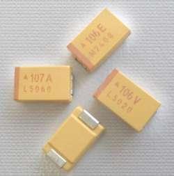
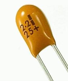
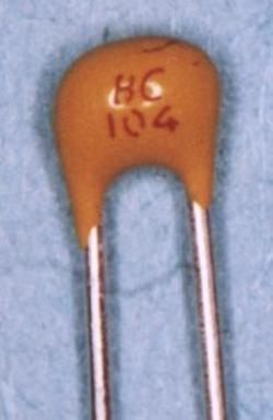
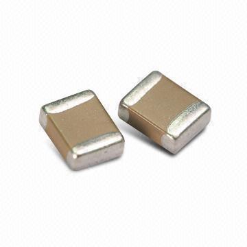
10 Capacitor Types Polarized Capacitors: Electrolytic Tantalum Non-Polarized Capacitors: Ceramic

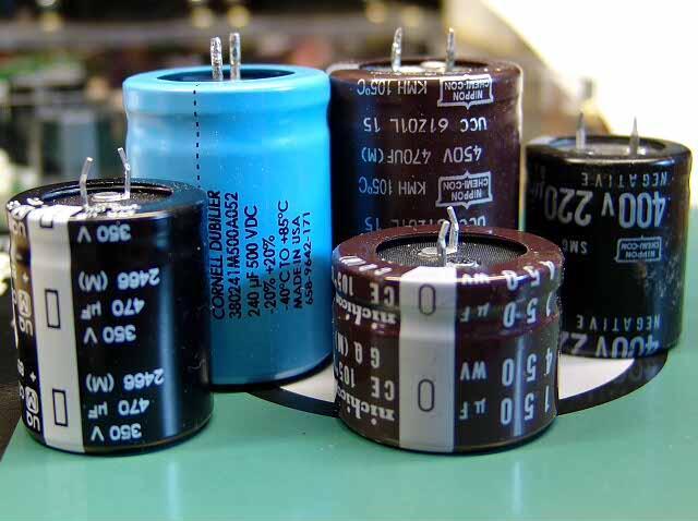
11 Capacitor Value Most large capacitors have their value indicated on them, typically in uf or mf. Tolerance values can be -50%/+100%, -20%/+80%, simply +/-20%, or 5% or better, but cost a lot more! Ex: 68uF, with a maximum 400V Ex2: 47uF, with a maximum 400V


12 Ceramic Capacitor Value Smaller capacitors are measured in pf (Pico-Farad). Ex: 10 x 1000pF = 10nF 20% = 0.01uF 20%

.")


13 Diodes Diodes are a one way electrical valve. Current can only go in one direction (ie. polarized). VRRM: Maximum reverse breakdown voltage. Vf: Forward voltage drop. Im: Maximum forward current. Package: Typically axial, but can be in any package type. Metal housing for cooling in large diodes. Have a marking (usually a stripe) at one end to denote the cathode.


14 Schottky Diode Schottky diodes are special; their forward voltage drops are very low. They are used in the input of DC electronic equipment to protect against reverse polarity and in highly efficient DC/DC switching converters. Packages range widely.

 low power zener diodes are glass construction,")
15 Zener Diodes Zener diodes are used in reverse bias, where a fixed voltage is created across it. They are designed for a small range of current. Must select accordingly. Often (but not always) low power zener diodes are glass construction, orange/red in colour, with a black bar denoting the cathode.


16 LEDs LED: Light Emitting Diodes Long leg = Positive (Anode) Notch in glass = Negative (Cathode) side CAUTION: Check datasheet to be sure! Intensity: Varies from 1 millicandela to multiple Candela Size: SMT to 3mm, 5mm etc.. Colour: Single wave length, infrared -> visible spectrum -> ultra violet.


17 Fuses Fuses protect electronic circuits from overcurrent a filament blows open when current too high must be replaced after blowing. Fuse types Type: slow blow, medium blow, fast blow, resettable Current: wide range Voltage: from a few volts to thousands of volts AC & DC Resettable Fuse: PTC Positive Temperature Coefficient. Very popular for new electronic devices. Resistance increases dramatically when heated thus reducing current to near zero, resistance drops back down when cooled (when overcurrent event removed). Slow reaction times compared to medium and fast blow fuses.


18 Breaker Breakers are made of two different types of metals, where it bends when heated due to current. When it bends, the connection is tripped. They are resettable.


19 DPST DPDT Switches Switches interrupt current flow through a connection. Some terminology: Poles: How many contacts are changed in one event. Throw: Number of different positions Types: Rotary, Slide, Dip, Toggle, etc. NO: Normally Open NC: Normally Closed Latch vs. Momentary Latch remains in position Momentary is temporary


20 Relays Relays are electrically controlled switches An input current through a coil activates a switch. An input voltage triggers a solid state device to turn on/off. Size: Depends on current and voltage ratings Solid State Mechanical Relay


. Very useful for")


21 Inductors Inductors are coils that store magnetic energy created from electrical current. Units are Henry (nh,uh,mh or H). Very useful for communications equipment, transformers, filters, converters, etc. Often coils consist of a wire wrapped around permeable magnetic materials to increase inductance value. Can be either color coded, number coded or non-marked. Can be SMT, coils, radial or axial lead, shielded/unshielded.

 Package: SMT, Through Hole, Panel")
22 Transistors Transistors are electronics current valves: Three legs: Collector, Base, Emitter Types: PNP and NPN Power: Can be low power, or high power Gain: Low gain, or high gain (Darlington) Package: SMT, Through Hole, Panel mount.


23 MOSFET MOSFETs are voltage controlled current valves: Very low internal resistance Good high-current control Very sensitive to ESD Some have built in ESD or over voltage protection Some have overcurrent protection Three legged device: Drain, Gate, Source. Extremely popular for most modern electronics due to their ease of fabrication, and excellent properties.
 Pin spacing conforms to JEDEC Standards and are typically 0.")
24 Integrated Circuits (IC s) Integrated Circuits come in a variety of sizes and packages: Dual In-line Package (DIP) DIP IC s are used on through-hole Printed Circuit Boards The same number of pins in a row on opposite sides of the package 6, 8, 14, 16, 18, 20, 22, 24, 32, 40, 48 and 64 pins (narrow and wide) Pin spacing conforms to JEDEC Standards and are typically Can be soldered directly to PCB or inserted into a socket making it more serviceable Can be very sensitive to ESD
25 Integrated Circuits (IC s) Pin identification is standardized in industry With the centred indicator (notch) on your left, Pin 1 is located directly below this spot Starting at Pin 1, the numbers increase going right to the last pin, then continue directly across from the last pin, going left to the last pin.
, Pin Grid Array (PGA), Ball Grid Array (BGA), etc. Pin count varies from as little as 4 pins to 672 pins and up Pin spacing varies by package but is typically.5 mm (0.")
26 Integrated Circuits (IC s) Surface Mount Device/Technology (SMD or SMT) Small-Outline Integrated Circuit (SOIC), Thin Small-Outline Package (TSOP), Quad Flat Pack (QFP), Plastic Leaded Chip Carrier (PLCC), Pin Grid Array (PGA), Ball Grid Array (BGA), etc. Pin count varies from as little as 4 pins to 672 pins and up Pin spacing varies by package but is typically.5 mm ( ) Devices are soldered directly to PCB making serviceability difficult Can be very sensitive to ESD
Component Identification
 Generic Skills for Microelectronic Engineers Component Identification AIM: To be able to identify common electronic components used in miniature and medium power applications. Methods of labelling, range
Electronic Components. Identification of components and handling precautions to protect them from damage due to electrostatic discharge
 Electronic Components Identification of components and handling precautions to protect them from damage due to electrostatic discharge 1 Passive Components Resistors Capacitors Inductors Diodes Interface
M328 version ESR inductance capacitance meter multifunctional tester DIY
 M328 version ESR inductance capacitance meter multifunctional tester DIY About transistor Multifunction Tester: The tester uses 3.7V rechargeable lithium battery (battery model: 14500) powered portable
IR add-on module circuit board assembly - Jeffrey La Favre January 27, 2015
 IR add-on module circuit board assembly - Jeffrey La Favre January 27, 2015 1 2 For the main circuits of the line following robot you soldered electronic components on a printed circuit board (PCB). The
SUBELEMENT T6 Electrical components: semiconductors; circuit diagrams; component functions 4 Exam Questions - 4 Groups
 SUBELEMENT T6 Electrical components: semiconductors; circuit diagrams; component functions 4 Exam Questions - 4 Groups 1 T6A Electrical components: fixed and variable resistors; capacitors and inductors;
Circuit Components Lesson 4 From: Emergency Management Ontario
 4.1 Amplifier Fundamentals The role of a amplifier is to produce an output which is an enlarged reproduction of the features of the signal fed into the input. The increase in signal by an amplifier is
FCC Technician License Course
 FCC Technician License Course 2014-2018 FCC Element 2 Technician Class Question Pool Presented by: Tamiami Amateur Radio Club (TARC) WELCOME To the SECOND of 4, 3-hour classes presented by TARC to prepare
TS500 Assembly guide. Soldering. TS500 Assembly guide Main PCB 1. Diodes. Document revision 1.2 Last modification : 17/12/16
 TS500 Assembly guide Safety warning The kits are main powered and use potentially lethal voltages. Under no circumstance should someone undertake the realisation of a kit unless he has full knowledge about
Technician Licensing Class T6
 Technician Licensing Class T6 Amateur Radio Course Monroe EMS Building Monroe, Utah January 11/18, 2014 January 22, 2014 Testing Session Valid dates: July 1, 2010 June 30, 2014 Amateur Radio Technician
Long Loopstick Antenna
 Long Loopstick Antenna Wound on a 3 foot length of PVC pipe, the long loopstick antenna was an experiment to try to improve AM radio reception without using a long wire or ground. It works fairly well
Electronic Components (Elements)
") Lecture_3 Electronic Components (Elements) Instructor: IBRAHIM ABU-ISBEIH 25 July 2011 Reverse Engineering 1 Objectives: After completing this class, you will be able to identify the most commonly used
Lecture_3 Electronic Components (Elements) Instructor: IBRAHIM ABU-ISBEIH 25 July 2011 Reverse Engineering 1 Objectives: After completing this class, you will be able to identify the most commonly used
N3ZI Kits General Coverage Receiver, Assembly & Operations Manual (For Jun 2011 PCB ) Version 3.33, Jan 2012
 Version 3.33, Jan 2012") N3ZI Kits General Coverage Receiver, Assembly & Operations Manual (For Jun 2011 PCB ) Version 3.33, Jan 2012 Thank you for purchasing my general coverage receiver kit. You can use the photo above as a
N3ZI Kits General Coverage Receiver, Assembly & Operations Manual (For Jun 2011 PCB ) Version 3.33, Jan 2012 Thank you for purchasing my general coverage receiver kit. You can use the photo above as a
T6A4. Electrical components; fixed and variable resistors, capacitors, and inductors; fuses, switches, batteries
 Amateur Radio Technician Class Element Course Presentation ti ELEMENT SUB-ELEMENTS Technician Licensing Class Supplement T Electrical/Electronic Components Exam Questions, Groups T - FCC Rules, descriptions
Electronic Components
 Electronic Components Arduino Uno Arduino Uno is a microcontroller (a simple computer), it has no way to interact. Building circuits and interface is necessary. Battery Snap Battery Snap is used to connect
HEAT ACTIVATED SWITCH KIT
 TEACHING RESOURCES SCHEMES OF WORK DEVELOPING A SPECIFICATION COMPONENT FACTSHEETS HOW TO SOLDER GUIDE REACT TO THE TEMPERATURE WITH THIS HEAT ACTIVATED SWITCH KIT Version 2.1 Heat Activated Switch Teaching
Building The DC Beeper from Jackson Harbor Press A Morse code voltmeter / DC switch
 Building The DC Beeper and from Jackson Harbor Press Operating A Morse code voltmeter / DC switch The DC Beeper kit is a combination of a Morse code voltmeter with 20 mv resolution and a DC switch. The
12V Dimmer Kit, version 2
 12V Dimmer Kit, version 2 User Manual Description The 12V Dimmer Kit V2 is an especially efficient PWM (pulse-width modulation) controller for 12V loads up to 60 watts. It features a single dial control
Bi-Directional DC Motor Speed Controller 5-32Vdc (3166v2)
") General Guidelines for Electronic Kits and Assembled Modules Thank you for choosing one of our products. Please take some time to carefully read the important information below concerning use of this product.
General Guidelines for Electronic Kits and Assembled Modules Thank you for choosing one of our products. Please take some time to carefully read the important information below concerning use of this product.
Part Derating Parameters
 Part Derating Parameters Capacitors Fixed Aluminum (Electrolytic) Fixed Ceramic Fixed Mica/Glass Fixed Paper/Plastic Fixed Tantalum (Non- Solid) Reverse Voltage Fixed Tantalum (Solid) Reverse Voltage Variable
LED ROBOT BLINKER KIT
 LED ROBOT BLINKER KIT MODEL K-17 Assembly and Instruction Manual ELENCO Copyright 2016, 1998 by ELENCO Electronics, Inc. All rights reserved. Revised 2013 REV-P 753217 No part of this book shall be reproduced
Basic Electronics. Chapter 2, 3A (test T5, T6) Basic Electrical Principles and the Functions of Components. PHYS 401 Physics of Ham Radio
 Basic Electrical Principles and the Functions of Components. PHYS 401 Physics of Ham Radio") Basic Electronics Chapter 2, 3A (test T5, T6) Basic Electrical Principles and the Functions of Components Figures in this course book are reproduced with the permission of the American Radio Relay League.
Basic Electronics Chapter 2, 3A (test T5, T6) Basic Electrical Principles and the Functions of Components Figures in this course book are reproduced with the permission of the American Radio Relay League.
Introduction. Inductors in AC Circuits.
 Module 3 AC Theory What you ll learn in Module 3. Section 3.1 Electromagnetic Induction. Magnetic Fields around Conductors. The Solenoid. Section 3.2 Inductance & Back e.m.f. The Unit of Inductance. Factors
V6.2 SoftRock Lite Builder s Notes. November 17, 2006
 V6.2 SoftRock Lite Builder s Notes November 17, 2006 Be sure to use a grounded tip soldering iron in building the v6.2 SoftRock circuit board. The soldering iron needs to have a small tip, (0.05-0.1 inch
AltiumLive 2017: Component selection for EMC
 AltiumLive 2017: Component selection for EMC Martin O Hara Victory Lighting Ltd Munich, 24-25 October 2017 Component Selection Passives resistors, capacitors and inductors Discrete diodes, bipolar transistors,
Instant MTBF Data Input Sheet Commercial / Bellcore TR Integrated Circuits, Bipolar, Digital
 Instant MTBF Data Input Sheet Commercial / Bellcore TR-332 Probabilistic Software, Inc. http://www.e-mtbf.com System / Equipment Name: Assembly Name: Quantity Of This Assembly: Parts List Number: Environment:
Electronic Components
 Engineering Project (1) Lecture_2 Electronic Components (Elements) Instructor: Eng. IBRAHIM ABU-ISBEIH 6 March 2012 Eng. Ibrahim Abu-Isbeih 1 Objectives: After completing this class, you will be able to
Switcher Assembly guide. Switcher Assembly guide 1. Soldering. 2. Switcher3 vs Switcher2. 3. PCB split.
 Safety warning The kits are main powered and use potentially lethal voltages. Under no circumstance should someone undertake the realisation of a kit unless he has full knowledge about safely handling
ELECTRIC CIRCUITS AND ELECTRONICS
 Circuitos eléctricos y electrónicos ELECTRIC CIRCUITS AND ELECTRONICS Technology, programming and robotics II Electric Circuitos circuits eléctricos and y electronics electrónicos AN ELECTRICAL CIRCUIT
Capacitors, diodes, transistors
 Capacitors, diodes, transistors capacitors charging and time response filters (impedance) semi-conductor diodes rectifiers transformers transistors CHM6158C - Lecture 3 1 Capacitors Symbol 2 Capacitors
5v AC R. 12v. 1kohm. F=35KHz oscilloscope. 3 Final Project OFF. ON Toggle Switch. Relay 5v 2N3906 2N uF LM311. IR Detector +5v GND LED PNP NPN
 3 Final Project Diode 103 IR Detector OFF ON Toggle Switch IR Detector +5v Push Button IR 100uF LED + GND LDR C Preset R 7805 IN GND OUT Relay 5v + PNP 2N3906 1 Kohm NPN 2N3904 4 3 2 1 555 5 6 7 8 4 3
Project: Electromagnetic Ring Launcher
 Project: Electromagnetic Ring Launcher Introduction: In science museums and physics-classrooms an experiment is very commonly demonstrated called the Jumping Ring or Electromagnetic Ring Launcher. The
EGN1935: ECE (Ad)Ventures. Today s Menu. EGN1935: ECE (Ad)Ventures
Ventures. Today s Menu. EGN1935: ECE (Ad)Ventures") Today s Menu Electrical Components > Polarization > Component values Assembly Techniques > Soldering/Desoldering Introduction to Logic Design See Reference on web-site: MIT 6.270 book 1 There will be a
Today s Menu Electrical Components > Polarization > Component values Assembly Techniques > Soldering/Desoldering Introduction to Logic Design See Reference on web-site: MIT 6.270 book 1 There will be a
Electronics 1. Voltage/Current Resistors Capacitors Inductors Transistors
 Electronics 1 Voltage/Current Resistors Capacitors Inductors Transistors Voltage and Current Simple circuit a battery pushes some electrons around the circuit how many per second? Water The easiest way
University of Technology, Jamaica School of Engineering. Electrical Workshop Notes On Electrical components
 University of Technology, Jamaica School of Engineering Electrical Workshop Notes On Electrical components Resistors Resistors are fundamental components in electronic circuits. A resistor is constructed
Cornerstone Electronics Technology and Robotics I Week 19 Electrical Relays
 Cornerstone Electronics Technology and Robotics I Week 19 Electrical Relays Administration: o Prayer o Turn in quiz o Review voltage regulators: Review SPST, SPDT, DPST, DPDT switches http://cornerstonerobotics.org/curriculum/lessons_year1/er%20week8,%
Build this Direct Digital Synthesizer "Development Kit" By: Diz Gentzow, W8DIZ
 Build this Direct Digital Synthesizer "Development Kit" By: Diz Gentzow, W8DIZ A great tutorial for adding a keypad to the DDS Kit by Bruce, W8BH This manual has been prepared to be read directly on screen.
DIODE / TRANSISTOR TESTER KIT
 DIODE / TRANSISTOR TESTER KIT MODEL DT-100K Assembly and Instruction Manual Elenco Electronics, Inc. Copyright 1988 Elenco Electronics, Inc. Revised 2002 REV-K 753110 DT-100 PARTS LIST If you are a student,
PM124 Installation Instructions. See important note about revisions of this board on the last page.
 Marchand Electronics Inc. PO Box 473, Webster, NY 14580 Tel:(716) 872-0980 Fax:(716) 872-1960 info@marchandelec.com http://www.marchandelec.com (c)1997 Marchand Electronics Inc. PM124 Installation Instructions
Temperature activated switch
 Build instructions, circuit explanation and example applications Issue 1.5 Product information: www.kitronik.co.uk/quicklinks/2113/ TEACHER Temperature activated switch Introduction About the project kit
Pre-certification Electronics Questions. Answer the following with the MOST CORRECT answer.
 Electronics Questions Answer the following with the MOST CORRECT answer. 1. The cathode end terminal of a semiconductor diode can be identified by: a. the negative sign marked on the case b. a circular
16 Bit Micro Experimenter Assembly and Check out Instructions
 16 Bit Micro Experimenter Assembly and Check out Instructions The kit you purchased that includes PCB, schematic, complete parts list and these assembly instructions. A top picture of the complete assembly
Patton Robotics, LLC.
 Patton Robotics LLC Patton Robotics T3 Motherboard Assembly Instructions Version 1.1 Patton Robotics, LLC. 61 Hagan Drive New Hope, PA 18938 Phone: 609-977-5525 Email: pattonrobotics@gmail.com Copyright
LED ROBOT BLINKER KIT
 LED ROBOT BLINKER KIT MODEL K-17 Assembly and Instruction Manual Elenco Electronics, Inc. Copyright 1989, 1998 Elenco Electronics, Inc. Revised 2001 REV-J 753217 PARTS LIST If any parts are missing or
Lab Equipment EECS 311 Fall 2009
 Lab Equipment EECS 311 Fall 2009 Contents Lab Equipment Overview pg. 1 Lab Components.. pg. 4 Probe Compensation... pg. 8 Finite Instrumentation Impedance. pg.10 Simulation Tools..... pg. 10 1 - Laboratory
BYOC Vibrato Kit Instructions BA662A version
 BYOC Vibrato Kit Instructions BA662A version Please read these instructions very thoroughly before building even if you are an experience builder. Because of the layout, there is a certain order which
700 SERIES 20V BIPOLAR ARRAY FAMILY
 Device Engineering Incorporated 385 East Alamo Drive Chandler, AZ 85225 Phone: (480) 303-0822 Fax: (480) 303-0824 E-mail: admin@deiaz.com 700 SERIES 20V BIPOLAR ARRAY FAMILY FEATURES 20V bipolar analog
Industrial / Power Factory Automation
 Vishay Intertechnology, Inc. Industrial / Power www.vishay.com One of the World s Largest Manufacturers of Discrete Semiconductors and Passive Components Industrial / Power Motor Drives 4 Testers 5 Control
Main improvements are increased number of LEDs and therefore better temperature indication with one Celsius degree increments.
 LED Thermometer V2 (Fahrenheit/Celsius/±1 ) PART NO. 2244754 After completing this great starter kit, users will have a nice interactive LED thermometer. You will learn one principle how temperature can
DIODE / TRANSISTOR TESTER KIT
 DIODE / TRANSISTOR TESTER KIT MODEL DT-100K 99 Washington Street Melrose, MA 02176 Phone 781-665-1400 Toll Free 1-800-517-8431 Visit us at www.testequipmentdepot.com Assembly and Instruction Manual Elenco
Chap. 5 Electronic Components and Sensing Devices
 1 Chap. 5 Electronic Components and Sensing Devices Today, practically all mechanical devices contain some sort of electronic components. The function of a product often relies on the integration of mechanical
FM RADIO KIT ESSENTIAL INFORMATION. Version 2.0 GET IN TUNE WITH THIS
 ESSENTIAL INFORMATION BUILD INSTRUCTIONS CHECKING YOUR PCB & FAULT-FINDING MECHANICAL DETAILS HOW THE KIT WORKS GET IN TUNE WITH THIS FM RADIO KIT Version 2.0 Build Instructions Before you start, take
Laboratory 6 Diodes and Transistors
 Laboratory 6 page 1 of 6 Laboratory 6 Diodes and Transistors Introduction In this lab, you will build and test circuits using diodes and transistors. You will use a number of different types of diodes,
OBSOLETE. Features. ! HEXFET Power MOSFET output! Bounce-free operation! 3,750 V RMS
 OBSOLETE Data Sheet No. PD136 rev J PVO42P Microelectronic Power IC HEXFET Power MOSFET Single Pole, Normally Open + Ring Detector -4V, 12mA AC/DC General Description The PVO42P Photovoltaic is a dual-pole,
555 Astable Kit MitchElectronics 2018
 555 Astable Kit MitchElectronics 2018 www.mitchelectronics.co.uk CONTENTS Introduction 3 Schematic 3 How It Works 4 Materials 6 Construction 7 Important Information 8 Page 2 INTRODUCTION The 555 timer
Semiconductors, ICs and Digital Fundamentals
 Semiconductors, ICs and Digital Fundamentals The Diode The semiconductor phenomena. Diode performance with ac and dc currents. Diode types: General purpose LED Zener The Diode The semiconductor phenomena
Experiment 15: Diode Lab Part 1
 Experiment 15: Diode Lab Part 1 Purpose Theory Overview EQUIPMENT NEEDED: Computer and Science Workshop Interface Power Amplifier (CI-6552A) (2) Voltage Sensor (CI-6503) AC/DC Electronics Lab Board (EM-8656)
FCC Technician License Course
 FCC Technician License Course 2018-2022 FCC Element 2 Technician Class Question Pool Presented by: Tamiami Amateur Radio Club (TARC) WELCOME To the SECOND of 3, 4-hour classes presented by TARC to prepare
Contents. Acknowledgments. About the Author
 Contents Figures Tables Preface xi vii xiii Acknowledgments About the Author xv xvii Chapter 1. Basic Mathematics 1 Addition 1 Subtraction 2 Multiplication 2 Division 3 Exponents 3 Equations 5 Subscripts
TV Remote. Discover Engineering. Youth Handouts
 Discover Engineering Youth Handouts Electronic Component Guide Component Symbol Notes Amplifier chip 1 8 2 7 3 6 4 5 Capacitor LED The amplifier chip (labeled LM 386) has 8 legs, or pins. Each pin connects
Design and Technology
 E.M.F, Voltage and P.D E.M F This stands for Electromotive Force (e.m.f) A battery provides Electromotive Force An e.m.f can make an electric current flow around a circuit E.m.f is measured in volts (v).
Line-Following Robot
 1 Line-Following Robot Printed Circuit Board Assembly Jeffrey La Favre October 5, 2014 After you have learned to solder, you are ready to start the assembly of your robot. The assembly will be divided
BYOC Vibrato Kit Instructions BA6110 version
 BYOC Vibrato Kit Instructions BA6110 version Please read these instructions very thoroughly before building even if you are an experience builder. Because of the
GCSE Electronics. Scheme of Work
 GCSE Electronics Scheme of Work Week Topic Detail Notes 1 Practical skills assemble a circuit using a diagram recognize a component from its physical appearance (This is a confidence building/motivating
Sherlock Solder Models
 Introduction: Sherlock Solder Models Solder fatigue calculations in Sherlock are accomplished using one of the many solder models available. The different solder models address the type of package that
10 2 2,13,15,16,46 27, non-inductive ,26,
 HANDS-ON RADIO PARTS LIST (Thanks, John AF4WM and Steve AD7KR) Updated through Experiment 129 Quantities assume all parts available for re-use MAX QTY EXPERIMENT NOTES 1/4 WATT RESISTOR (All values are
UNIVERSITY OF NORTH CAROLINA AT CHARLOTTE Department of Electrical and Computer Engineering
 UNIVERSITY OF NORTH CAROLINA AT CHARLOTTE Department of Electrical and Computer Engineering EXPERIMENT 2 BASIC CIRCUIT ELEMENTS OBJECTIVES The purpose of this experiment is to familiarize the student with
Low Voltage, High Current Time Delay Circuit
 Low Voltage, High Current Time Delay Circuit In this circuit a LM339 quad voltage comparator is used to generate a time delay and control a high current output at low voltage. Approximatey 5 amps of current
Manual Version July 2007
 Manual Version 1.2 - July 2007 Page 1 Table of Contents Section1: M3 Phono Board Build...3 Phono Board Parts List...3 Preparation...4 Fitting the Valve Bases...6 Installing the Resistors...7 Starting the
Chapter 3. Electricity, Components and Circuits. Metric Units
 Chapter 3 Electricity, Components and Circuits Metric Units 1 T5B02 -- What is another way to specify a radio signal frequency of 1,500,000 hertz? A. 1500 khz B. 1500 MHz C. 15 GHz D. 150 khz T5B07 --
Systems Engineering. Passive Components. v1.2 March itic.
 Systems Engineering Passive Components Pere Palà itic http://itic.cat v1.2 March 2012 Resistors Resistor Types Resistors Ubiquitous Uncritical Surface mount chip Metal film Carbon Wirewound Precision resistors
PCB Design (with EAGLE tutorial) TA: Robert Likamwa ELEC 424, Fall 2010
 TA: Robert Likamwa ELEC 424, Fall 2010") PCB Design (with EAGLE tutorial) TA: Robert Likamwa ELEC 424, Fall 2010 Printed Circuit Boards What are they? How can I make one? 424 Project description Eagle Tutorial http://www.electronicmanufacturers.co.za/
PCB Design (with EAGLE tutorial) TA: Robert Likamwa ELEC 424, Fall 2010 Printed Circuit Boards What are they? How can I make one? 424 Project description Eagle Tutorial http://www.electronicmanufacturers.co.za/
Digital Electronics & Chip Design
 Digital Electronics & Chip Design Lab Manual I: The Utility Board 1999 David Harris The objective of this lab is to assemble your utility board. This board, containing LED displays, switches, and a clock,
SPACE WAR GUN KIT MODEL K-10. Assembly and Instruction Manual. Elenco Electronics, Inc.
 SPACE WAR GUN KIT MODEL K-10 Assembly and Instruction Manual Elenco Electronics, Inc. Copyright 1989 Elenco Electronics, Inc. Revised 2001 REV-H 753210A PARTS LIST Contact Elenco Electronics (address/phone/e-mail
Metal Detector. Student Lab Guide. Engineering Teaching Laboratory. Lab Partner(s)
") Metal Detector Student Lab Guide Engineering Teaching Laboratory Name Date Lab Partner(s) NEW TERMS Electric Circuit: Electric circuits are paths for transmitting electric current, or moving electricity.
Metal Detector Student Lab Guide Engineering Teaching Laboratory Name Date Lab Partner(s) NEW TERMS Electric Circuit: Electric circuits are paths for transmitting electric current, or moving electricity.
Instructions for Building the Pulsed Width Modulation Circuit. MC-12 (DC Motor Controller or PWM) From Electronic Light Inc. (revised kit 8/08)
 From Electronic Light Inc. (revised kit 8/08)") Instructions for Building the Pulsed Width Modulation Circuit MC-12 (DC Motor Controller or PWM) From Electronic Light Inc. (revised kit 8/08) Using this circuit for a pulsed DC current to your cell. Do
Instructions for Building the Pulsed Width Modulation Circuit MC-12 (DC Motor Controller or PWM) From Electronic Light Inc. (revised kit 8/08) Using this circuit for a pulsed DC current to your cell. Do
Bill of Materials: Metronome Kit PART NO
 Metronome Kit PART NO. 2168325 The metronome kit allows you to build your own working electronic metronome. Features include a small speaker, flashing LED, and the ability to switch between several different
Basic Electronics for Model Railroaders By Gene Jameson NMRA Convention, Kansas City MO., August 5 12, 2018
 Basic Electronics for Model Railroaders By Gene Jameson NMRA Convention, Kansas City MO., August 5 12, 2018 Please turn off your cell phones. If it rings I will ask you to leave the room and I will NOT
Features. +12V to +36V MIC nf. High-Side Driver with Overcurrent Trip and Retry
 MIC0 MIC0 High-Speed High-Side MOSFET Driver General Description The MIC0 high-side MOSFET driver is designed to operate at frequencies up to 00kHz (khz PWM for % to 00% duty cycle) and is an ideal choice
MP573 Assembly guide. Soldering. MP573 Assembly guide PCB split PCB split. Document revision 2.2 Last modification : 22/08/17
 MP573 Assembly guide Safety warning The kits are main powered and use potentially lethal voltages. Under no circumstance should someone undertake the realisation of a kit unless he has full knowledge about
DARK ACTIVATED COLOUR CHANGING NIGHT LIGHT KIT
 TEACHING RESOURCES SCHEMES OF WORK DEVELOPING A SPECIFICATION COMPONENT FACTSHEETS HOW TO SOLDER GUIDE CREATE SOOTHING LIGHTING EFFECTS WITH THIS DARK ACTIVATED COLOUR CHANGING NIGHT LIGHT KIT Version
nonlinearcircuits QUO/LPF build notes version 2 11 April 2014
 nonlinearcircuits QUO/LPF build notes version 2 11 April 2014 This circuit is based on the 4 pole LPF in Electronotes 41, tho has been subject to a number of tweaks and prods to bring it to where it is
Basic Electronics Refresher
 Basic Electronics Refresher Current and Voltage Current is the rate of flowing electric charge in a conductor. Voltage is the potential difference (electric driving force) applied between two points to
A3930 and A3931. Demo Board Schematic/Layout SCHEMATIC A DB
 SCHEMATIC A3930-31-DB LAYOUT 2 3 4 BILL OF MATERIALS A3930/ Demo Board Rev 3 Component List Last Updated: 15/07/2014 Part Value Package Description RS Part Part Value Package Description RS Part C1 1000uF
Library Expert Through hole Families
 Non polarized Axial Diameter Leaded Component Library Expert Through hole Families Resistor (RESAD) Capacitor Non polarized (CAPAD) Fuse Axial Diameter (FUSAD) Inductor Axial Diameter (INDAD) Non polarized
700 SERIES 20V BIPOLAR ARRAY FAMILY
 Device Engineering Incorporated 0 E. Fifth St. Tempe, AZ 858 Phone: (480) 303-08 Fax: (480) 303-084 E-mail: admin@deiaz.com 00 SERIES 0V BIPOLAR ARRAY FAMILY FEATURES 0V bipolar analog array family of
PM24 Installation Instructions
 Marchand Electronics Inc. PO Box 473, Webster, NY 14580 Tel:(716) 872-0980 Fax:(716) 872-1960 info@marchandelec.com http://www.marchandelec.com (c)1997 Marchand Electronics Inc. PM24 Installation Instructions
LDB-1 Kit Instructions Page 1 of 8
 LDB-1 Kit Instructions Page 1 of 8 Important Information Congratulations and thank you for your purchase of the LDB-1 Little Drummer Boy Analog Drum Machine Kit! Before you start, please read the enclosed
Warm Tube Clock. Before we start, please make sure that you have all required parts that come for the main board :
 Warm Tube Clock Assembly Instructions for the main board Introduction Congratulations on your purchase of OSH Nixie Tube Clock. In this document you will see all steps you need to follow in order to successfully
FM Audio/Squelch Board by Steve Dold, W6KCS w6kcs (at) stevedold (dot) com
 stevedold (dot) com") FM Audio/Squelch Board by Steve Dold, W6KCS w6kcs at stevedold dot com Board hardware version 7-8 Firmware version 7.x This board connects to an FM receiver's discriminator/detector and provides squelched,
FM Audio/Squelch Board by Steve Dold, W6KCS w6kcs at stevedold dot com Board hardware version 7-8 Firmware version 7.x This board connects to an FM receiver's discriminator/detector and provides squelched,
DELUXE STEREO AMPLIFIER KIT
 TEACHING RESOURCES SCHEMES OF WORK DEVELOPING A SPECIFICATION COMPONENT FACTSHEETS HOW TO SOLDER GUIDE CREATE YOUR OWN SPEAKER DOCK WITH THIS DELUXE STEREO AMPLIFIER KIT Version 2.0 Index of Sheets TEACHING
Instructions for Building the Pulsed Width Modulation Circuit. MC-12 (DC Motor Controller or PWM) From Electronic Light Inc. (revised kit 5/08)
 From Electronic Light Inc. (revised kit 5/08)") Instructions for Building the Pulsed Width Modulation Circuit MC-12 (DC Motor Controller or PWM) From Electronic Light Inc. (revised kit 5/08) Using this circuit for a pulsed DC current to your cell. Do
Instructions for Building the Pulsed Width Modulation Circuit MC-12 (DC Motor Controller or PWM) From Electronic Light Inc. (revised kit 5/08) Using this circuit for a pulsed DC current to your cell. Do
AC/DC POWER SUPPLY KIT
 AC/DC POWER SUPPLY KIT MODEL K-11 Assembly and Instruction Manual ELENCO Copyright 2016, 1989 by ELENCO All rights reserved. Revised 2016 REV-O 753211 No part of this book shall be reproduced by any means;
Light activated switch
 Build instructions, circuit explanation and example applications Issue 1.6 Product information: www.kitronik.co.uk/quicklinks/2112/ TEACHER Light activated switch Introduction About the project kit This
NCS1 Series Isolated 1W 4:1 Input Single Output DC/DC Converters
 NCS1 Series SELECTION GUIDE FEATURES UL 9 recognised 4:1 Wide range voltage input Operating temperature range -4 C to 15 C with derating 1kVDC Isolation Hi Pot Test 3.3V, 5V & 12V outputs No electrolytic
SoftRock v6.0 Builder s Notes. May 22, 2006
 SoftRock v6.0 Builder s Notes May 22, 2006 Be sure to use a grounded tip soldering iron in building the v6.0 SoftRock circuit board. The soldering iron needs to have a small tip, (0.05-0.1 inch diameter),
Name My end of year 8 Target = Teacher. OLSJ Design & Technology Electronic Products. Overall Progress Effort Rating ABCDEFG.
 Name My end of year 8 Target = Teacher OLSJ Design & Technology Electronic Products Week 1 2 3 4 5 6 7 Lesson Objectives What will you learn about today? 1. Circuit Symbols and circuit diagram 2. Drilling
Wiring Manual NEScaf April 2010 (August 2006)
") Wiring Manual NEScaf April 2010 (August 2006) Switched Capacitor Audio Filter The NEScaf is a switched capacitor audio filter (acronym SCAF) built around a building-block type filter chip. The NEScaf will
Wiring Manual NEScaf April 2010 (August 2006) Switched Capacitor Audio Filter The NEScaf is a switched capacitor audio filter (acronym SCAF) built around a building-block type filter chip. The NEScaf will
Instructions for Building the Pulsed Width Modulation Circuit. MC-12 (DC Motor Controller or PWM) From Electronic Light Inc. (revised kit 10/03/08)
 From Electronic Light Inc. (revised kit 10/03/08)") Instructions for Building the Pulsed Width Modulation Circuit MC-12 (DC Motor Controller or PWM) From Electronic Light Inc. (revised kit 10/03/08) Congratulations on your purchase of the MC-12 DC Motor
Instructions for Building the Pulsed Width Modulation Circuit MC-12 (DC Motor Controller or PWM) From Electronic Light Inc. (revised kit 10/03/08) Congratulations on your purchase of the MC-12 DC Motor
CHAPTER 1. Introduction
 CHAPTER 1 Introduction Welcome to the world of Electrical and Computer Engineering. In the series of laboratory exercises presented in this text, we hope to give you a "hands-on" tour of much of what this
ELECTRONICS AND ELECTRICITY
 INTRODUCTION ELECTRONICS ND ELECTRICITY The science of Electronics and Electricity makes a very important contribution to our everyday existence. Electricity is concerned with the generation, transmission