Smart Garment Design
|
|
|
- Cecil Hoover
- 5 years ago
- Views:
Transcription


1 Smart Garment Design 5. Basic Electronics Sungmin Kim SEOUL NATIONAL UNIVERSITY Definition of Circuit A closed loop of electricity that contains a power source and a load Components Power source Something that provides electricity Load Something that makes use of the electricity in the circuit Conductor Material that permits the flow of electricity Circuit Diagram A clear, concise representation of the components and connections in a circuit Battery Resistor Diode 2


2 Electricity Flow It flows from the positive terminal of the battery to positive terminal of the LED It then flows through LED to the negative terminal of the battery to complete the loop It likes to follow the path of least resistance Non-resistive alternate path is preferred It may create a short circuit 3 Short Circuit Definition A closed loop of electricity that has a power source but no load Happens when electricity is fed from the positive end of the battery directly into the negative end Results Malfunction of circuit Drainage of the battery Severe result can occur including smoke, melted wires, and damaged components Prevention Insulation material that do not conduct electricity is used 4
 The measure of a material s ability to prevent the flow of electricity V I R V I R V R I A quick-and-dirty way")

 (3 2) R 58. 82 I 0.")
3 Ohm s Law Voltage (V) The difference in electrical energy between two points Current (A) The quantity or amount of electrical energy passing a particular point Resistance (Ω) The measure of a material s ability to prevent the flow of electricity V I R V I R V R I A quick-and-dirty way to light up an LED 5 Ohm s Law The problem in the circuit on the previous slide The LED is receiving a bit more than the desirable amount of current Excessive current can shorten the LED s life or even burn it out You should create a circuit that respects the needs of its components ( Vs V f ) R I V source voltage which is supplied by the battery V s f forward voltage which is needed for the component R desired resistance of the circuit According to the datasheet of an LED... Forward voltage is 2V Required current is 17mA or 0.017A ( Vs V f ) (3 2) R I

4 Ohm s Law 7 Ohm s Law Resistors are come in set values There may not always be the exact register that meets your needs Preparation of a 58.82Ω resistor Use the next largest value, in this case a 62Ω resistor Combine two resistors in a row, in this case 56+3=59Ω 8


 Forward voltage drop of LED = 1.8~2.2V With a 3V battery.")
5 Ohm s Law Reading a resistor s resistance Using color chart, calculator web site, or smart phone application Reading method Silver or gold band is on the right and read from left to right» First two bands will indicate the first two digit of the number» The third band indicates the multiplier for that digit» The fourth band indicates the tolerance 9 Series and Parallel Series Components are connected in a row Electricity flows through one, into the next, and then into the next Factors to be considered Power source must supply adequate voltage Voltage drops before it moves on to the next component Example) Forward voltage drop of LED = 1.8~2.2V With a 3V battery... First LED=3V, Second LED=1V, Third=0V Battery should provide at least 6V 10


6 Series and Parallel Parallel Components are connected side by side Each with an independent connection to power and ground Factors to be considered Each LED receives the same amount of voltage Current is divided between LEDs 11 Polarity Certain electronic components have a predetermined polarity It matters which way the component is connected in the context of a circuit Ex) Diode» A component that only allows electricity to pass through it in one direction» LED (Light Emitting Diode) 12

7 Multimeter A special tool to detect electricity A dial to select a particular function Probes that are used to make connections with whatever you are measuring 13 Multimeter Continuity The simplest but most useful function that measures the continuity or conductivity Check the continuity of a questionable connection Check for short circuits by placing the probes in two places that are not supposed to be connected Can be used to check the conductivity of a material Resistance Check the value of a fixed resistor Monitor the changing resistance of a variable resistor Determine the resistance of a material like conductive thread or fabric Voltage Check the state of a battery Determine if components of a circuit are receiving the voltage that they need Current The meter needs to be in series with the circuit 14
 Current")


8 Multimeter Probe connection Voltage (Parallel) Current (Series) 15 Alligator Clip Circuit Advantage Alligator clips provide a quick way to prototype simple, temporary circuits Disadvantage Alligator clips do have a tendency to slide around a bit 16


9 Wire Circuit Method Wires are used to create connections between components Twisting, bending, or crimping establish a basic physical connection Soldering those points establishes a secure electrical connection Wrap resistor leg around LED leg Trim resistor leg Wrap stripped wire around LED and resistor legs Solder wires Apply heat shrink tubing 17 Wire Circuit 18


10 Breadboard Circuit Advantage Easy to connect and disconnect through-hole components Connections beneath a breadboard 19 Breadboard Circuit Placing Components Male headers Prepare resistor for breadboard 20


11 Protoboard Circuit Advantage Makes connections that are far more secure and robust than a breadboard 21 Conductive Thread Circuit Characteristics Allows the creation of soft and pliable circuits Sew connections rather than solder them Preparation of components for sewing 22


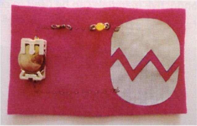
12 Conductive Thread Circuit Sew components using conductive thread Untrimmed tails of thread can lead to short circuits Trimmed thread trails Secure the knots with fabric glue 23 Conductive Fabric Circuit Advantage Intricate circuits can be created, cut, and adhered quickly Check the space between components Cover conductive fabric Iron to adhere the conductive fabric Conductive fabric circuit 24

13 Conclusion Circuit Advantage Disadvantage Alligator Clip Circuit Allows quick integration of nonstandard components like DIY sensors Useful for testing components Bulky and not optimal for complex circuits Unstable and potential for shorts Wire Circuit Extremely flexible and customizable Not practical for complex circuits Robustness depends on choice of wire and amount of strain placed on circuit Breadboard Circuit Protoboard Circuit Conductive Thread Circuit Conductive Fabric Circuit Quick and efficient Easy to modify Secure connections Potentially smaller than a breadboard Flexible, pliable, customizable, and fashionable Faster approach to soft circuits Potential for interesting designs Bulky and not terribly robust Looks weird on a shirt Still a bit bulky Difficult to integrate with textiles Potential for shorts Some conductive threads have significant resistance Time consuming Subject to shorts Still requires sewing 25 Switches Definition Something that enables, prevents, or diverts the flow of electricity Use Creates or breaks the physical connection of two conductors Intentional input Activate a circuit by doing something as pushing a button on a circuit board Passive sensor Activate a circuit by doing something as subtle and intuitive as standing up, blinking eyes, or a hug 26

14 Switches Poles and Throws Pole Refers to the number of separate circuits controlled by the switch Throw Refers to the number of positions each pole can be connected to SPST Rocker Switch SPDT Toggle switch between two LEDs SPDT Toggle switch used as a SPST 27 Switches Types of Switches Maintained switches Stay in whatever state you put them in» Light switch in a room Momentary switches Normally open» Refers to a momentary switch whose default state is for the contacts to be open» If it is activated by the user, the switch will close Normally closed» Refers to a momentary switch whose default state is for the contacts to be closed» When the switch is activated, the switch will open, deactivating the attached circuit 28


15 Off-the-Shelf Switches Switches Tactile buttons Momentary buttons that provide light tactile feedback Latching buttons Maintained switches that respond to being pressed - Press it once and the button will stay closed - Press it again and the button will stay open Toggle switches Maintained switch that is operated by a lever Slide switches Maintained switch that is controlled by moving the switch back and forth Microswitches Highly sensitive momentary switch that can be operated by a small movement Tilt switches Open or close based on the orientation of the switch - Single or multiaxial 29 Textile Switches Sandwich Switch Switches 30


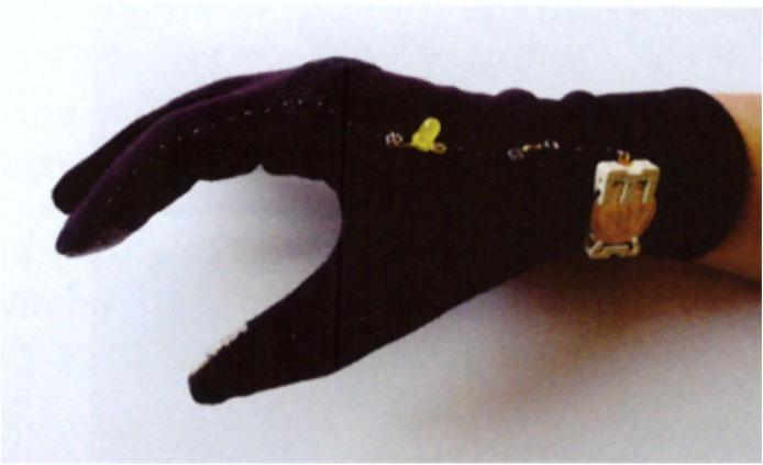

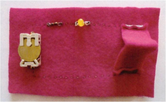
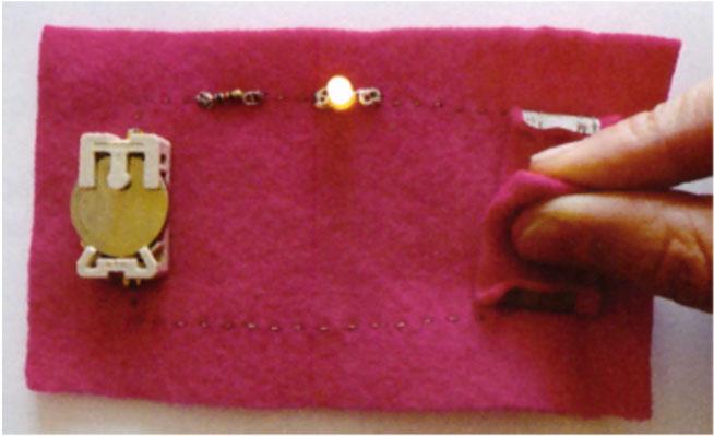
16 Textile Switches Contact Switch Switches 31 Textile Switches Bridge Switch Switches Pinch Switch 32


17 Textile Switches Social Switches Switches When properly planned, a switch can create the opportunity for a social interaction 'Power Me Up' Circuit 'You Complete Me' Circuit 'We're All In This Together' Circuit 33 Hard-Soft Connection Connections Multi-conductor band Snap Button Breakout Board 34


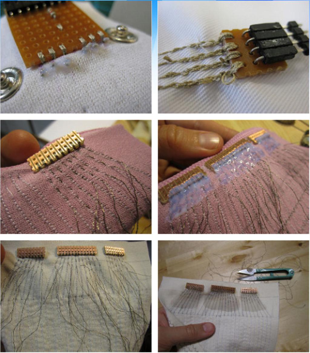

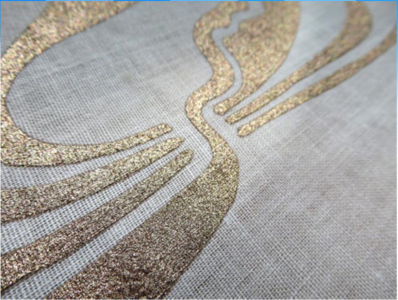
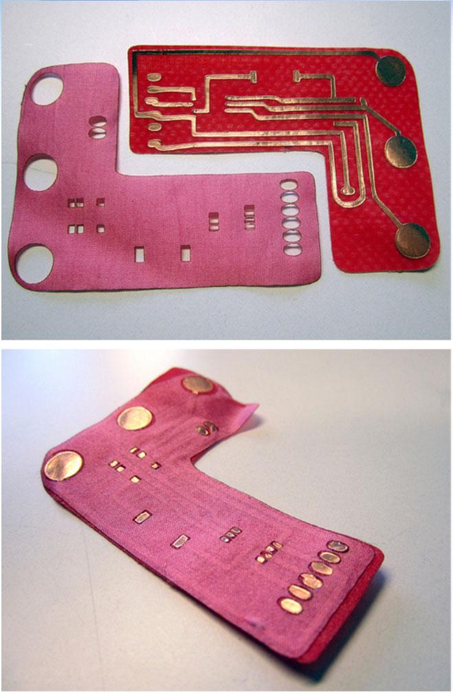
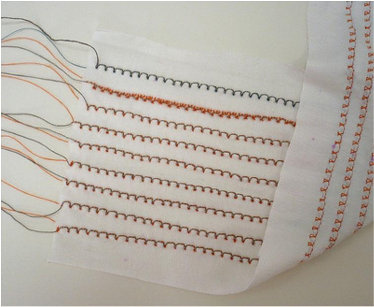
18 Hard-Soft Connection Connections Zigzag stitch Magnet clasp/conductive thread Perforated board/conductive Thread 35 Traces Connections Screen-Printed Copper Paint Laser-Cut Mask Stretch Cable 36
Aim: To learn the resistor color codes and building a circuit on a BreadBoard. Equipment required: Resistances, millimeter, power supply
 Understanding the different components Aim: To learn the resistor color codes and building a circuit on a BreadBoard Equipment required: Resistances, millimeter, power supply Resistors are color coded
Experiment 2. Ohm s Law. Become familiar with the use of a digital voltmeter and a digital ammeter to measure DC voltage and current.
 Experiment 2 Ohm s Law 2.1 Objectives Become familiar with the use of a digital voltmeter and a digital ammeter to measure DC voltage and current. Construct a circuit using resistors, wires and a breadboard
CMSC838. Tangible Interactive Assistant Professor Computer Science
 CMSC838 Tangible Interactive Computing Week 04 Lecture 05 Feb 17, 2014 Electronic Components Sensing and Sensors Human Computer Interaction Laboratory @jonfroehlich Assistant Professor Computer Science
Experiment 3. Ohm s Law. Become familiar with the use of a digital voltmeter and a digital ammeter to measure DC voltage and current.
 Experiment 3 Ohm s Law 3.1 Objectives Become familiar with the use of a digital voltmeter and a digital ammeter to measure DC voltage and current. Construct a circuit using resistors, wires and a breadboard
Unit 1 Electronics Name: Form:
 Unit 1 Electronics Name: Form: Electronics Electronics is the study of components and techniques used to be able to build circuits controlled by electricity. An electronic system uses discrete components.
Line-Following Robot
 1 Line-Following Robot Printed Circuit Board Assembly Jeffrey La Favre October 5, 2014 After you have learned to solder, you are ready to start the assembly of your robot. The assembly will be divided
Lab 2.4 Arduinos, Resistors, and Circuits
 Lab 2.4 Arduinos, Resistors, and Circuits Objectives: Investigate resistors in series and parallel and Kirchoff s Law through hands-on learning Get experience using an Arduino hat you need: Arduino Kit:
Resistance Measurements (Measure all of your resistors, since even those that are labeled the same can be at least a little different)
") Resistors We begin by learning how to read the values of resistors and to measure the values using a digital multimeter (DMM). Resistors are the most common and simplest electrical component. In an electrical
Resistors We begin by learning how to read the values of resistors and to measure the values using a digital multimeter (DMM). Resistors are the most common and simplest electrical component. In an electrical
Intro to Electronics. Week 1
 Intro to Electronics Week 1 1 What is included? DIY ELECTRONICS 2 Lights http://www.flickr.com/photos/oskay/3423822454/ Intro to Electronics, Week 1 Last modified April 16, 2012 3 Sounds http://www.flickr.com/photos/createdigitalmedia/3701158293/
NERVE TESTER KIT MODEL K-20. Assembly and Instruction Manual. Elenco Electronics, Inc.
 NERVE TESTER KIT MODEL K-20 Assembly and Instruction Manual Elenco Electronics, Inc. Copyright 1989 Elenco Electronics, Inc. Revised 2002 REV-E 753220 PARTS LIST If you are a student, and any parts are
HANDS-ON ACTIVITY 4 BUILDING SERIES AND PARALLEL CIRCUITS BACKGROUND WIRING DIRECTIONS
 ACTIVITY 4 BUILDING SERIES AND PARALLEL CIRCUITS BACKGROUND Make sure you read the background in Activity 3 before doing this activity. WIRING DIRECTIONS Materials per group of two: one or two D-cells
Electrical Components and their Functions
 Electrical Components and their Functions Electricity & Electronics All electrical appliances and electronic devices depend on electrical circuits. The main difference between electricity & electronics
Electrical Functions Notes
 Electrical Functions Notes Electrical Function An electrical function is the role that a component plays in the control or transformation of electric current. Power Supplies Power supply is the electrical
An important note about your Charged Up Exploration Kit.
 ChargedUp Hands On Exploration Kit First An important note about your. DO NOT ASSUME that you will see something at the tournament because it was in this kit. This supplemental study material IS NOT part
Ohm's Law and DC Circuits
 Physics Lab II Ohm s Law Name: Partner: Partner: Partner: Ohm's Law and DC Circuits EQUIPMENT NEEDED: Circuits Experiment Board Two Dcell Batteries Wire leads Multimeter 100, 330, 560, 1k, 10k, 100k, 220k
ENGR 40M Project 2a: Useless box
 ENGR 40M Project 2a: Useless box Prelab due 24 hours before your section, April 16 19, 2018 Lab due before your section, April 24 27, 2018 1 Objectives In this lab, you ll assemble a useless box like the
AME140 Lab #2 INTRODUCTION TO ELECTRONIC TEST EQUIPMENT AND BASIC ELECTRONICS MEASUREMENTS
 INTRODUCTION TO ELECTRONIC TEST EQUIPMENT AND BASIC ELECTRONICS MEASUREMENTS The purpose of this document is to guide students through a few simple activities to increase familiarity with basic electronics
A Deluxe LED Blinky That You Can Build!
 Lux Spectralis A Deluxe LED Blinky That You Can Build! Assembly Instructions Contents Step 1: Parts check... 2 Step 2: Tool check... 3 Step 3: Install the computer chip... 3 Step 4: Install the resistors...
Breadboard Primer. Experience. Objective. No previous electronics experience is required.
 Breadboard Primer Experience No previous electronics experience is required. Figure 1: Breadboard drawing made using an open-source tool from fritzing.org Objective A solderless breadboard (or protoboard)
DIODE / TRANSISTOR TESTER KIT
 DIODE / TRANSISTOR TESTER KIT MODEL DT-100K 99 Washington Street Melrose, MA 02176 Phone 781-665-1400 Toll Free 1-800-517-8431 Visit us at www.testequipmentdepot.com Assembly and Instruction Manual Elenco
Embedded Systems Analog Electronics
 Embedded Systems Analog Electronics Units physical units = length [meter], mass [kilogram], time [second] force - [Newton]: kg m/s 2 (F=ma) torque - [N m] energy - [joule]: 1N acting through distance of
Introduction to the Laboratory
 Memorial University of Newfoundland Department of Physics and Physical Oceanography Physics 2055 Laboratory Introduction to the Laboratory The purpose of this lab is to introduce you to some of the equipment
Manual Version July 2007
 Manual Version 1.2 - July 2007 Page 1 Table of Contents Section1: M3 Phono Board Build...3 Phono Board Parts List...3 Preparation...4 Fitting the Valve Bases...6 Installing the Resistors...7 Starting the
IPR LA-3 KIT last update 15 march 06
 IPR LA-3 KIT last update 15 march 06 PART-2: Audio Circuitry CIRCUIT BOARD LAYOUT: Power and Ground Distribution Now that your power supply is functional, it s time to think about how that power will be
Oregon State University Lab Session #1 (Week 3)
") Oregon State University Lab Session #1 (Week 3) ENGR 201 Electrical Fundamentals I Equipment and Resistance Winter 2016 EXPERIMENTAL LAB #1 INTRO TO EQUIPMENT & OHM S LAW This set of laboratory experiments
Oregon State University Lab Session #1 (Week 3) ENGR 201 Electrical Fundamentals I Equipment and Resistance Winter 2016 EXPERIMENTAL LAB #1 INTRO TO EQUIPMENT & OHM S LAW This set of laboratory experiments
Value Location Qty Transistors 2N5485 Q1, Q2, 4 Q3, Q4 2N5087 Q5 1. Trim Pots 250k VTRIM 1. Potentiometers C500k Speed 1. Toggle Switch On/On Vibe 1
 P-90 BUILD INSTRUCTIONS Thank you for your purchase of our P-90 kit! We have completely redesigned our entire line of kits to be the most user friendly, while still maintaining their same great sound!
SPACE WAR GUN KIT MODEL K-10. Assembly and Instruction Manual. Elenco Electronics, Inc.
 SPACE WAR GUN KIT MODEL K-10 Assembly and Instruction Manual Elenco Electronics, Inc. Copyright 1989 Elenco Electronics, Inc. Revised 2001 REV-H 753210A PARTS LIST Contact Elenco Electronics (address/phone/e-mail
The Art of Electrical Measurements
 The Art of Electrical Measurements Purpose: Introduce fundamental electrical test and measurement tools and the art of making electrical measurements. Equipment Required Prelab 1 Digital Multimeter 1 -
DIODE / TRANSISTOR TESTER KIT
 DIODE / TRANSISTOR TESTER KIT MODEL DT-100K Assembly and Instruction Manual Elenco Electronics, Inc. Copyright 1988 Elenco Electronics, Inc. Revised 2002 REV-K 753110 DT-100 PARTS LIST If you are a student,
Figure 1. CheapBot Smart Proximity Detector
 The CheapBot Smart Proximity Detector is a plug-in single-board sensor for almost any programmable robotic brain. With it, robots can detect the presence of a wall extending across the robot s path or
Never power this piano with anything other than a standard 9V battery!
 Welcome to the exciting world of Digital Electronics! Who is this kit intended for? This kit is intended for anyone from ages 13 and above and assumes no previous knowledge in the field of hobby electronics.
HANDS-ON LAB INSTRUCTION SHEETS MODULE
 HANDS-ON LAB INSTRUCTION SHEETS MODULE 1 MEASURING RESISTANCE AND VOLTAGE NOTES: 1) Each student will be assigned to a unique Lab Equipment number MS01-MS30 which will match to a Tool Kit and a Radio Shack
EET 150 Introduction to EET Lab Activity 1 Resistor Color Codes and Resistor Value Measurement
 Required Parts, Software and Equipment Parts 20 assorted 1/4 watt resistors 5% tolerance Equipment Required Solderless Experimenters' Board Digital Multimeter Optional Alligator clip leads hookup wire
Lab 2 Electrical Safety, Breadboards, Using a DMM
 Lab 2 Electrical Safety, Breadboards, Using a DMM Objectives concepts 1. Safety hazards related to household electricity and electronics equipment 2. Differences between schematic and breadboard representations
Digital Electronics & Chip Design
 Digital Electronics & Chip Design Lab Manual I: The Utility Board 1999 David Harris The objective of this lab is to assemble your utility board. This board, containing LED displays, switches, and a clock,
Simon Tilts Assembly Guide
 Page 1 of 20 Simon Tilts Assembly Guide Introduction Simon Tilts is a memory game very similar to Simon Says, but instead of pressing buttons, the player is challenged to rotate the device in a specific
Give one or two examples of electrical devices that you have personally noticed getting warm when they are turned on.
 Resistors We begin by learning how to read the values of resistors and to measure the values using a digital multimeter (DMM). Resistors are the most common and simplest electrical component. In an electrical
Nano v3 pinout 19 AUG ver 3 rev 1.
 Nano v3 pinout NANO PINOUT www.bq.com 19 AUG 2014 ver 3 rev 1 Nano v3 Schematic Reserved Words Standard Arduino ( C / C++ ) Reserved Words: int byte boolean char void unsigned word long short float double
Electric Circuit Experiments
 Electric Circuit Experiments 1. Using the resistor on the 5-resistor block, vary the potential difference across it in approximately equal increments for eight different values (i.e. use one to eight D-
Team Xecuter Joycon Mod By: XxWiReDxX
 Team Xecuter Joycon Mod By: XxWiReDxX Works With Every Switch SX OS Works with every Nintendo Switch and every firmware version! Play Every Game With SX OS you can play all your favorite games straight
Lab 3 DC CIRCUITS AND OHM'S LAW
 43 Name Date Partners Lab 3 DC CIRCUITS AND OHM'S LAW AMPS + - VOLTS OBJECTIVES To learn to apply the concept of potential difference (voltage) to explain the action of a battery in a circuit. To understand
ELECTRONICS STARTER KIT
 ELECTRONICS STARTER KIT (MAP 474 - N02QQ) R These five small self-assembly circuits cover basic principles of electronics and can be adapted for numerous practical application. The five circuits include
Circuit Board Assembly Instructions for Babuinobot 1.0
 Circuit Board Assembly Instructions for Babuinobot 1.0 Brett Nelson January 2010 1 Features Sensor4 input Sensor3 input Sensor2 input 5v power bus Sensor1 input Do not exceed 5v Ground power bus Programming
PS2-SMC-06 Servo Motor Controller Interface
 PS2-SMC-06 Servo Motor Controller Interface PS2-SMC-06 Full Board Version PS2 (Playstation 2 Controller/ Dual Shock 2) Servo Motor Controller handles 6 servos. Connect 1 to 6 Servos to Servo Ports and
Pi-Cars Factory Tool Kit
 Pi-Cars Factory Tool Kit Posted on January 24, 2013 Welcome to the factory: Welcome to where you will learn how to build a Pi-Car, we call it the Pi-Cars Factory. We hope that this page contains all you
Assembly and User Guide
 Assembly and User Guide AtariPunkr is an adjustable stepped tone generator. AtariPunkr provides hours of fun everyone! Powered by: 9V Battery Outputs: Mylar Speaker (Included) Stereo Output (3.5mm Jack)
Introduction. Pictures in this lab have been taken from Pre-Lab Homework
 Introduction This lab relates to material in Hecht, Chapter 18. In this lab you will explore the concepts of circuits, resistors, and capacitors, by actually building a small circuit that is yours to keep!
DC CIRCUITS AND OHM'S LAW
 July 15, 2008 DC Circuits and Ohm s Law 1 Name Date Partners DC CIRCUITS AND OHM'S LAW AMPS - VOLTS OBJECTIVES OVERVIEW To learn to apply the concept of potential difference (voltage) to explain the action
STEADY HAND GAME WITH LATCHING LED
 ESSENTIAL INFORMATION BUILD INSTRUCTIONS CHECKING YOUR PCB & FAULT-FINDING MECHANICAL DETAILS HOW THE KIT WORKS TEST YOUR HAND-EYE COORDINATION WITH THIS STEADY HAND GAME WITH LATCHING LED Version 2.0
Welcome to the DIY Thirsty Plant Kit - Manual
 Welcome to the DIY Thirsty Plant Kit - Manual This is a step-by-step guide to making your own Thirsty Plant Detector. The equipment you should have at your station are wire strippers, wire cutters, wooden
12V Dimmer Kit, version 2
 12V Dimmer Kit, version 2 User Manual Description The 12V Dimmer Kit V2 is an especially efficient PWM (pulse-width modulation) controller for 12V loads up to 60 watts. It features a single dial control
LED ROBOT BLINKER KIT
 LED ROBOT BLINKER KIT MODEL K-17 Assembly and Instruction Manual Elenco Electronics, Inc. Copyright 1989, 1998 Elenco Electronics, Inc. Revised 2001 REV-J 753217 PARTS LIST If any parts are missing or
555 Morse Code Practice Oscillator Kit (draft 1.1)
") This kit was designed to be assembled in about 30 minutes and accomplish the following learning goals: 1. Learn to associate schematic symbols with actual electronic components; 2. Provide a little experience
This kit was designed to be assembled in about 30 minutes and accomplish the following learning goals: 1. Learn to associate schematic symbols with actual electronic components; 2. Provide a little experience
Frivolous Engineering Useless Machine Soldering Instructions
 Frivolous Engineering Useless Machine Soldering Instructions The electronics assembly for the Useless Machine is very easy to solder together. It consists of 11 parts as shown in the photo. Required tools
Name My end of year 8 Target = Teacher. OLSJ Design & Technology Electronic Products. Overall Progress Effort Rating ABCDEFG.
 Name My end of year 8 Target = Teacher OLSJ Design & Technology Electronic Products Week 1 2 3 4 5 6 7 Lesson Objectives What will you learn about today? 1. Circuit Symbols and circuit diagram 2. Drilling
Conductive Thread. Created by Becky Stern. Last updated on :10:08 AM EDT
 Conductive Thread Created by Becky Stern Last updated on 2015-06-17 08:10:08 AM EDT Guide Contents Guide Contents Overview Tools & supplies Prep thread and fabric Stitching around circuit boards Tying
Signal Lights Demonstration Video Time Duration: - 38 sec. Use the right hand mouse button for video control.
 Tip: - Working Turntable Signals and Cabin Lights using Gold TC7.0F1 and Above Hi All, At long last I completed the project to have working signals and cabin lights on my turntable. This is a record of
Blue Ring Tester Kit Assembly & User Manual
 Blue Ring Tester Kit Assembly & User Manual Alltronics LLC/AnaTek Instruments 2761 Scott Blvd, Santa Clara, CA, 95050, USA March 2015 Edition Tel: 408-778-3868, Fax: 408-778-2558, E mail : tech@alltronics.com
Growler Getter. Supplies: ½ yard main fabric. ½ yard Insul-Shine. 8 x 10 piece of Fusible Fleece 2. ¼ yard or fat quarter of coordinating fabric
 Supplies: ½ yard main fabric ½ yard Insul-Shine 8 x 10 piece of Fusible Fleece 2 ¼ yard or fat quarter of coordinating fabric 1 9 x 12 sheet of Steam-A-Seam 2 1 yard nylon cord 1 cord stop Coordinating
4-20 MA CURRENT LOOP SIMULATOR USING A PT100 RTD TEMPERATURE TRANSMITTER
 4-20 MA CURRENT LOOP SIMULATOR USING A PT100 RTD TEMPERATURE TRANSMITTER 4-20 ma SIMULATORS Analog signal transmission ( also digital sometimes ) using 4-20mA current loops is broadly used in industrial
ActivAting OrigAmi SEt guidebook
 Activating Origami SET GUIDEBOOK Welcome to the TEKNIKIO Activating Origami SET CONTENTS 4 YOUR MATERIALS 8 ORIGAMI PATTERNS 14 EXAMPLE ACTIVITIEs This is one in a series of sets. In this set you will
DARK ACTIVATED COLOUR CHANGING NIGHT LIGHT KIT
 TEACHING RESOURCES SCHEMES OF WORK DEVELOPING A SPECIFICATION COMPONENT FACTSHEETS HOW TO SOLDER GUIDE CREATE SOOTHING LIGHTING EFFECTS WITH THIS DARK ACTIVATED COLOUR CHANGING NIGHT LIGHT KIT Version
LOGIC PROBE KIT MODEL LP-525K. Assembly and Instruction Manual ELENCO
 LOGIC PROBE KIT MODEL LP-525K Assembly and Instruction Manual ELENCO Copyright 2013, 1994 by Elenco Electronics, Inc. All rights reserved. Revised 2013 REV-J 753241 No part of this book shall be reproduced
Tek-Bot Remote Control Transmitter Board Construction
 Tek-Bot Remote Control Transmitter Board Construction Purpose This tutorial illustrates the procedure for construction of the Transmitter board for the Tek-bot. A Guide to Soldering Many of you have soldered
Workshop Part Identification Lecture N I A G A R A C O L L E G E T E C H N O L O G Y D E P T.
 Workshop Part Identification Lecture N I A G A R A C O L L E G E T E C H N O L O G Y D E P T. Identifying Resistors Resistors can be either fixed or variable. The variable kind are called potentiometers
EECS40 Lab Introduction to Lab: Guide
 Aschenbach, Konrad Muthuswamy, Bharathwaj EECS40 Lab Introduction to Lab: Guide Objective The student will use the following circuit elements and laboratory equipment to make basic circuit measurements:
University of Jordan School of Engineering Electrical Engineering Department. EE 204 Electrical Engineering Lab
 University of Jordan School of Engineering Electrical Engineering Department EE 204 Electrical Engineering Lab EXPERIMENT 1 MEASUREMENT DEVICES Prepared by: Prof. Mohammed Hawa EXPERIMENT 1 MEASUREMENT
Lab 11: Circuits. Figure 1: A hydroelectric dam system.
 Description Lab 11: Circuits In this lab, you will study voltage, current, and resistance. You will learn the basics of designing circuits and you will explore how to find the total resistance of a circuit
MacombSO.org. The components in this kit are for low voltage / low current. They are to be used with (2) D cell batteries that you provide.
 D cell batteries that you provide.") ChargedUp Hands On Exploration Kit First An important note about your. DO NOT ASSUME you will see something at the tournament because it was in this kit. This data sheet is included to help you identify
ChargedUp Hands On Exploration Kit First An important note about your. DO NOT ASSUME you will see something at the tournament because it was in this kit. This data sheet is included to help you identify
Lab 4 OHM S LAW AND KIRCHHOFF S CIRCUIT RULES
 57 Name Date Partners Lab 4 OHM S LAW AND KIRCHHOFF S CIRCUIT RULES AMPS - VOLTS OBJECTIVES To learn to apply the concept of potential difference (voltage) to explain the action of a battery in a circuit.
Cornerstone Electronics Technology and Robotics I Week 19 Soldering Tutorial
 Cornerstone Electronics Technology and Robotics I Week 19 Soldering Tutorial Administration: o Prayer o Turn in quiz o Using fixed resistors design and build a voltage divider divides 5 volts in half.
Instrument Usage in Circuits Lab
 Instrument Usage in Circuits Lab This document contains descriptions of the various components and instruments that will be used in Circuit Analysis laboratory. Descriptions currently exist for the following
Electrical connections
 Electrical connections This worksheet and all related files are licensed under the Creative Commons Attribution License, version 1.0. To view a copy of this license, visit http://creativecommons.org/licenses/by/1.0/,
Value Location Qty Potentiometers C1M Distortion 1 A10k Volume 1. Footswitch 3PDT SW1 1. Jacks 1/4 Mono 2 DC Power 1
 Distortion BUILD INSTRUCTIONS Thank you for your purchase of our Distortion+ kit! We have completely redesigned our entire line of kits to be the most user friendly, while still maintaining their same
UNIVERSITY OF CALIFORNIA, BERKELEY. EE40: Introduction to Microelectronic Circuits Lab 1. Introduction to Circuits and Instruments Guide
 UNERSTY OF CALFORNA, BERKELEY EE40: ntroduction to Microelectronic Circuits Lab 1 ntroduction to Circuits and nstruments Guide 1. Objectives The electronic circuit is the basis for all branches of electrical
Building The DC Beeper from Jackson Harbor Press A Morse code voltmeter / DC switch
 Building The DC Beeper and from Jackson Harbor Press Operating A Morse code voltmeter / DC switch The DC Beeper kit is a combination of a Morse code voltmeter with 20 mv resolution and a DC switch. The
The Discussion of this exercise covers the following points:
 Exercise 5 Resistance and Ohm s Law EXERCISE OBJECTIVE When you have completed this exercise, you will be familiar with the notion of resistance, and know how to measure this parameter using an ohmmeter.
Practical 2.1 BASIC ELECTRICAL MEASUREMENTS AND DATA PROCESSING
 Practical 2.1 BASIC ELECTRICAL MEASUREMENTS AND DATA PROCESSING September 6, 2017 1 Introduction To measure electrical quantities one uses electrical measuring instruments. There are three main quantities
Simple Circuits Experiment
 Physics 8.02T 1 Fall 2001 Simple Circuits Experiment Introduction Our world is filled with devices that contain electrical circuits in which various voltage sources cause currents to flow. We use radios,
EET 1150 Lab 6 Ohm s Law
 Name EQUIPMENT and COMPONENTS Digital Multimeter Trainer with Breadboard Resistors: 220, 1 k, 1.2 k, 2.2 k, 3.3 k, 4.7 k, 6.8 k Red light-emitting diode (LED) EET 1150 Lab 6 Ohm s Law In this lab you ll
SoftRock v6.0 Builder s Notes. May 22, 2006
 SoftRock v6.0 Builder s Notes May 22, 2006 Be sure to use a grounded tip soldering iron in building the v6.0 SoftRock circuit board. The soldering iron needs to have a small tip, (0.05-0.1 inch diameter),
EE1020 Diodes and Resistors in Electrical Circuits Spring 2018
 PURPOSE The purpose of this project is for you to become familiar with some of the language, parts, and tools used in electrical engineering. You will also be introduced to some simple rule and laws. MATERIALS
Micro USB Lamp Kit TEACHING RESOURCES. Version 2.1 DESIGN A STYLISH LAMP WITH THIS
 TEACHING RESOURCES SCHEMES OF WORK DEVELOPING A SPECIFICATION COMPONENT FACTSHEETS HOW TO SOLDER GUIDE DESIGN A STYLISH LAMP WITH THIS Micro USB Lamp Kit Version 2.1 Index of Sheets TEACHING RESOURCES
Introduction to Electronics and Breadboarding Circuits
 Introduction to Electronics and Breadboarding Circuits What we're going to learn today: What is an electronic circuit? What kind of power is needed for these projects? What are the fundamental principles
Make an Altoids Flashlight.
 Make an Altoids Flashlight by JoshuaZimmerman on July 12, 2012 Table of Contents Make an Altoids Flashlight 1 Intro: Make an Altoids Flashlight 2 Step 1: Parts 2 Step 2: LED Holder 3 Step 3: Prepare Your
IR add-on module circuit board assembly - Jeffrey La Favre January 27, 2015
 IR add-on module circuit board assembly - Jeffrey La Favre January 27, 2015 1 2 For the main circuits of the line following robot you soldered electronic components on a printed circuit board (PCB). The
Experiment 3 Ohm s Law
 Experiment 3 Ohm s Law The goals of Experiment 3 are: To identify resistors based upon their color code. To construct a two-resistor circuit using proper wiring techniques. To measure the DC voltages and
BENCH METER Model>9803. Wavecom Instruments
 BENCH METER Model>9803 Wavecom Instruments 1 Basic Information This guide provides basic instructions for operating the Mastech M9803R Bench Digital Multimeter. The M9803R provides these features: Multiple
Revision: Jan 29, E Main Suite D Pullman, WA (509) Voice and Fax
 Voice and Fax") Revision: Jan 29, 2011 215 E Main Suite D Pullman, WA 99163 (509) 334 6306 Voice and Fax Overview The purpose of this lab assignment is to provide users with an introduction to some of the equipment which
Revision: Jan 29, 2011 215 E Main Suite D Pullman, WA 99163 (509) 334 6306 Voice and Fax Overview The purpose of this lab assignment is to provide users with an introduction to some of the equipment which
Building the Sawdust Regenerative Receiver
 Building the Sawdust Regenerative Receiver Introduction The Sawdust is a super regenerative receiver using the basic Armstrong design architecture. The receiver uses one toroidal transformer to provide
2.00AJ / 16.00AJ Exploring Sea, Space, & Earth: Fundamentals of Engineering Design Spring 2009
 MIT OpenCourseWare http://ocw.mit.edu 2.00AJ / 16.00AJ Exploring Sea, Space, & Earth: Fundamentals of Engineering Design Spring 2009 For information about citing these materials or our Terms of Use, visit:
Embedded Control. Week 1 (6/29/11)
") Embedded Control Week 1 (6/29/11) Week 1 15:00 Lecture Circuit theory, terminology Overview of elementary circuit components Reading circuit diagrams 16:00 Lab NXT GPIO with HiTechnic sensor expansion
Embedded Control Week 1 (6/29/11) Week 1 15:00 Lecture Circuit theory, terminology Overview of elementary circuit components Reading circuit diagrams 16:00 Lab NXT GPIO with HiTechnic sensor expansion
Line Following Circuit Board Wiring Guide
 Line Following Circuit Board Wiring Guide Soldering the Analog Optosensors 1. Obtain a line following printed circuit board from the store as well as three analog optosensors (w/6 resistors). 2. Remove
Congratulations on your purchase of the SparkFun Arduino ProtoShield Kit!
 Congratulations on your purchase of the SparkFun Arduino ProtoShield Kit! Well, now what? The focus of this guide is to aid you in turning that box of parts in front of you into a fully functional prototyping
SKDG Cable Repair Kit Instructions
 SKDG Cable Repair Kit Instructions Description Having to repair your EasyHeat cable is an extremely rare occurrence. Damage is almost always a function of field conditions, such as impacts with tools.
Resistive components in circuits
 Resistive components in circuits Learners should be able to: (a) describe the effect of adding resistors in series and (b) use equations for series and parallel resistor combinations resistors in series
Main improvements are increased number of LEDs and therefore better temperature indication with one Celsius degree increments.
 LED Thermometer V2 (Fahrenheit/Celsius/±1 ) PART NO. 2244754 After completing this great starter kit, users will have a nice interactive LED thermometer. You will learn one principle how temperature can
V (in volts) = voltage applied to the circuit, I (in amperes) = current flowing in the circuit, R (in ohms) = resistance of the circuit.
 = voltage applied to the circuit, I (in amperes) = current flowing in the circuit, R (in ohms) = resistance of the circuit.") OHM S LW OBJECTIES: PRT : 1) Become familiar with the use of ammeters and voltmeters to measure DC voltage and current. 2) Learn to use wires and a breadboard to build circuits from a circuit diagram.
OHM S LW OBJECTIES: PRT : 1) Become familiar with the use of ammeters and voltmeters to measure DC voltage and current. 2) Learn to use wires and a breadboard to build circuits from a circuit diagram.
Electronics Merit Badge Kit Theory of Operation
 Electronics Merit Badge Kit Theory of Operation This is an explanation of how the merit badge kit functions. There are several topics worthy of discussion. These are: 1. LED operation. 2. Resistor function
SpikerBox v1.3 DIY Instructions
 SpikerBox v. DIY Instructions Prepare yourself. In hours, you will have built your own SpikerBox to begin doing neuroscience and whatever your creative mind can conjure. Materials Needed:. A Backyard Brains