Design and Technology
|
|
|
- William Richard
- 5 years ago
- Views:
Transcription
1 E.M.F, Voltage and P.D E.M F This stands for Electromotive Force (e.m.f) A battery provides Electromotive Force An e.m.f can make an electric current flow around a circuit E.m.f is measured in volts (v). Potential Difference (p.d) Electric current will only flow between two points in a circuit if there is a Potential Difference between them. P.d is the difference in voltage between two points of a circuit. Potential difference is measured in volts. A potential difference (p.d) exists in this circuit because the battery is providing an e.m.f. Voltage The E.m.f creates a potential difference across the bulb We call the bottom rail (B) zero volts. If we do this we can find the voltage at A by measuring the p.d between A and the zero V point. In this case the top rail is at a voltage of 9v. Voltage is measured with a voltmeter.
2 Voltages around a Simple Circuit 1. circuits in your exercise books and write down what the voltage is at point C. Draw these 2. Draw these circuits and write down what the voltmeter would read in each case. 3. Draw this circuit and indicate which of the bulbs would light.
3 Resistance, Voltage and Current Ohms law Ohm s law states that when you plot voltage (V), against current (I) you get a straight line. The slope of this line is the resistance R. This can be written as V = I x R A conductor with a resistance of 1 ohm needs 1 volt to drive a current of 1 amp through it. Units of resistance Resistance is measured in Ohms (or Ω). 1 ohm is a rather small resistance. Most resistances we shall meet are much larger. 1 kilohm (1kΩ) = 1,000 Ω 1 megohm (1MΩ) = 1,000,000 Ω or 1,000 kω Calculations using Ohms law Use this to calculate : Current flowing resistance R1 voltage v
4 Electrical Current and Voltage Electrical Current The current flowing through part of a circuit is measured in Amps (short for amperes). The symbol is A. One amp is a large current and more often in electronic circuits we are measuring one thousandth of an ampere one milliamps or (ma) ma = 1A or 1mA = 1/1000A or 0.001A Measure the electrical current flowing through a resistor using the following circuit. Vary the e.m.f voltage V1 from 0v to 12v plot this against the current flowing through the multimeter (I). I and What do you notice about the relationship between the current and the voltage? Put a line through the points and measure the slope of the line. What is the value of the slope of the line?
5 Combining Resistors in series and parallel Draw the following circuits and calculate the equivalent resistance Series Combinations Parallel combinations Series/parallel combinations

6 Choosing the correct Resistor Standard Values Resistors are only made in certain values. They are based on the E12 series of preferred values. These are 10, 12, 15, 18, 22, 27, 33, 39, 47, 56, 68 and 82. This means that you can buy a standard 68R resistor, 680R, 6.8K, 68K and so on, (but not a 70R or a 67R resistor).
7 Calculating Resistance Resistors in series When you have resistors in series, the current has more resistance to flow through and the overall resistance is calculated by adding together the resistors. R = R1 + R2 = When you put resistors together in series the value of the two together is always higher. Resistors in Parallel When you put resistors in parallel you make an extra path for the current to flow down. The total current flowing is the current flowing through R1 and through R2 added together. R = R1 X R2 R1 R2 = When you put resistors together in parallel the value of the two together is always lower.
8 Choosing the correct Resistor Standard Values Resistors are only made in certain values. They are based on the E12 series of preferred values. These are 10, 12, 15, 18, 22, 27, 33, 39, 47, 56, 68 and 82. This means that you can buy a standard 68R resistor, 680R, 6.8K, 68K and so on, (but not a 70R or a 67R resistor). Choosing the correct resistor when using an LED Design and Technology For every LED there is a specified LED current (sometimes written I F the FORWARD current). If a higher current is passed through the LED it will overheat and possibly fail. The LED is a type of DIODE. When current passes through the diode it causes a voltage drop. For every LED there is a specified LED voltage (sometimes written V F the forward voltage drop). Circuits using LEDs need a resistor to limit the current flowing through the LED to the correct specified value (I F ). This is calculated using Ohm s Law (V = I * R ). To calculate the current flowing through the LED the equation is I = V / R, but the value for the voltage across the resistor is V SUPPLY V LED R = V S V LED I F Question 1. What resistor would be needed to limit the current through a red LED with a forward voltage drop of 2v to 10mA when using a 12v power supply?
9 Voltage divider circuits We can use resistors to give us a voltage at any point somewhere between the voltage of the top rail and bottom rail of the circuit. 1. Draw Circuit 1 and calculate what the voltage is at points A, B, C, D and E. Circuit 1 For this general circuit the voltage at point C is calculated as V c = V x R 2 R 1 + R 2 Draw the circuits and calculate the voltage at point C


10 Diode A diode is an electronic one way valve it allows current flow only in one direction. The negative end of the diode the CATHODE this has a to is The positive end is the ANODE Current will flow when the anode voltage is more than 0.7V higher than the cathode. Diodes are used to : 1. Protect circuits from having the batteries connected the wrong way around 2. To prevent components being damaged by the high voltage spike caused when a relay or solenoid coil is switched off 3. To turn ac into dc
11 Transistors A transistor has three leads. The base is used as an input. Current flowing into will control the current flowing to the output the collector. the base How a transistor behaves If a transistor is connected between a bulb and the 0V rail we can turn the bulb on and off with tiny changes to the current flowing into the base of the transistor. Voltages round a transistor When the transistor is off, the collector voltage is high When the transistor is on, the collector voltage is low The voltage at the base is never above 0.7V. Base resistor The base resistor R b is used to make sure that the current flowing into the base is small without R b the transistor may overheat and fail.


12 Sensors Input Devices for the Voltage Divider Circuit Use the diagrams below to show what sensors are needed to make a Light Sensor Darkness Sensor Moisture Sensor Dryness Sensor Heat Sensor Cold Sensor Draw the components needed for the Voltage Divider arrangement (both as symbols and as a sketch of the input device)


13 Switches A single throw switch is one that can be either OPEN or CLOSED. A double throw switch is one that closes one set contacts in one position and another set of contacts in the other position. of Normally open means that when the switch is in normal position the contacts are OPEN. its Single pole switches have only ONE set of contacts, double pole switches have TWO sets contacts. of Push to make means that the contacts are CLOSED when it is pushed. Push to break means that the contacts are OPEN when it is pushed. Push button switch Microswitch Reed switch Slide Toggle switch Rocker switch Switch Label each of the above what type of switching action does each switch have?


14 Relays A relay is a switch that is operated by a solenoid. Solenoids A solenoid uses a coil of wire to operate a moving plunger. When a current is passed through the coil it becomes magnetised and pulls the plunger in one direction when the current is removed a spring moves the plunger back. Relays Relays use a solenoid to open and close the switch contacts. A small current through the coil can open and close switch contacts that can pass much higher currents this is what makes relays so useful. Relays can have single or double pole contacts. They are usually double throw contacts with sets of normally open contacts and sets of normally closed contacts. When using a transistor sensor circuit the transistor is often used to switch the relay solenoid. When the solenoid coil is de energised there will be a voltage spike generated remember to use a diode across the relay coil to prevent damage to the transistor.

 nanofarads nf (0.")
15 Capacitors When a capacitor is connected across a potential difference (e.g. a battery) it will charge up until it reaches the same voltage as the applied voltage source. If a capacitor is connected in series with a capacitor then this process happens gradually this can be used to give a time delay. There are two types of capacitor. Electrolytic capacitors have larger values. They must be connected the right way round this is marked on the case. Non electrolytic capacitors usually have a lower capacitance. Capacitance is measured in farads. A farad is a very large capacitance most capacitors are usually: microfarads µf (one millionth of a farad, 0.000,001F) nanofarads nf (0.000,000,001 F or 1000 nf = 1µF) picofarads pf (0.000,000,000,001 F or 1000pF = 1 nf) Combining capacitors Capacitors in parallel Capacitors in series C1 x C2

16 Integrated Circuits Integrated Circuits (silicon chips) are made by treating small areas of silicon so they become semi conductors, to form miniature transistors, diodes, resistors and interconnections i.e. a complete circuit in miniature! These are put into a case. The commonest are DIL Dual In Line. Most of the chip is the case and wires the contained within the tiny square of silicon cases circuit is The connections to each pin are called the Pinout. This is the pinout for an NE555 timer IC In the circuits we will use, Pin 4 and Pin 8 are connected to + V In the monostable timer Pin 6 and Pin 7 are connected together the circuit is triggered by a signal voltage to Pin 2 and will stay on (Pin 3 high) until the voltage at Pin 6 reaches 6V (at which point Pin 3 will switch to low 0 V). This circuit can be used for many projects involving timing (e.g. leaving level crossing gates or lift doors open for a set period of time). In the astable flasher circuit Pin 2 and Pin 6 are connected together. Used like this the 555 chip can be used to produce flashing lights or warning beeps from a buzzer (or as an electronic clock pulse for other circuits or for motor speed control).
17 555 Monostable Timer Circuits Build the following circuits using Circuit Wizard. Add the probe and see how the capacitor charges up and discharges. Try adding a second LED (with current limiting resistor) between the 9V rail and output pin 3. Monostable Here the timer is triggered by applying a voltage for a short time to input pin 2 The ON period ends when the voltage at pin 7 (which rises as the capacitor charges up) reaches 6V These are approximate values for the ON period R (kω) C (μf) T (s) Try these and control the ON period of your circuit Use the circuit on the right to add a second switch. When Pin 4 is taken down 0V the circuit is reset and the output switched off.
18 555 Astable Timer Circuits Build the following circuits using Circuit Wizard. Add the probe and see how the capacitor charges up and discharges. When Pin 3 is ON the capcitor is charging up. When it reaches 6V at Pin 6 the IC switches OFF. The capacitor discharges until it reaches 3V. When Pin 2 drops to 3V this acts as a trigger pulse to switch the IC back on again. Using two variable resistors lets us control both the ON period and the OFF period. Try adding a second LED (with current limiting resistor) between the 9V rail and output pin 3.
19 Component Symbols


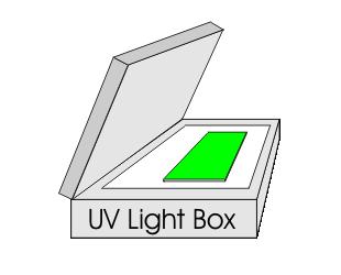
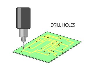
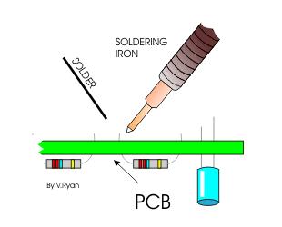
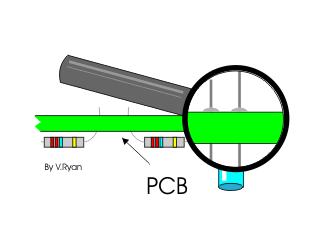
20 Producing a Printed Circuit Board Design and Technology

21
Process Components. Process component
 What are PROCESS COMPONENTS? Input Transducer Process component Output Transducer The input transducer circuits are connected to PROCESS COMPONENTS. These components control the action of the OUTPUT components
ELEXBO A-Car-Engineering
 1 Task: -Construct successively all schematic diagrams and describe your findings. -Describe also the differences between the previous electrical diagram. Construct this electrical circuit and describe
5v AC R. 12v. 1kohm. F=35KHz oscilloscope. 3 Final Project OFF. ON Toggle Switch. Relay 5v 2N3906 2N uF LM311. IR Detector +5v GND LED PNP NPN
 3 Final Project Diode 103 IR Detector OFF ON Toggle Switch IR Detector +5v Push Button IR 100uF LED + GND LDR C Preset R 7805 IN GND OUT Relay 5v + PNP 2N3906 1 Kohm NPN 2N3904 4 3 2 1 555 5 6 7 8 4 3
GCSE Electronics. Scheme of Work
 GCSE Electronics Scheme of Work Week Topic Detail Notes 1 Practical skills assemble a circuit using a diagram recognize a component from its physical appearance (This is a confidence building/motivating
Voltage Current V I. Resistors are colour-coded: the number of Ohms resistance is indicated by a series of coloured bands on the resistor.
 Introduction to Electronics Part 1: Some Basic Ideas and omponents urrent, Voltage and esistance urrent is a measure of the rate of flow of charge (unit: the Amp). Voltage is a measure of the force with
UNIT E1 (Paper version of on-screen assessment) A.M. WEDNESDAY, 8 June hour
 A.M. WEDNESDAY, 8 June hour") Candidate Name GCSE 46/0 Centre Number Candidate Number 0 ELECTRONICS UNIT E (Paper version of on-screen assessment) A.M. WEDNESDAY, 8 June 20 hour For s use 46 0000 Total Mark ADDITIONAL MATERIALS Information
Candidate Name GCSE 46/0 Centre Number Candidate Number 0 ELECTRONICS UNIT E (Paper version of on-screen assessment) A.M. WEDNESDAY, 8 June 20 hour For s use 46 0000 Total Mark ADDITIONAL MATERIALS Information
FACTFILE: GCSE Technology and Design
 FACTFILE: GCSE Technology and Design OPTION A: ELECTRONIC AND MICROELECTRONIC CONTROL SYSTEMS 2.14 Timers Monostable Learning Outcomes You should be able to: demonstrate knowledge and understanding of
FACTFILE: GCSE Technology and Design
 FACTFILE: GCSE Technology and Design OPTION A: ELECTRONIC AND MICROELECTRONIC CONTROL SYSTEMS 2.14 Timers Astable Learning Outcomes You should be able to: demonstrate knowledge and understanding of the
LM555 and LM556 Timer Circuits
 LM555 and LM556 Timer Circuits LM555 TIMER INTERNAL CIRCUIT BLOCK DIAGRAM "RESET" And "CONTROL" Input Terminal Notes Most of the circuits at this web site that use the LM555 and LM556 timer chips do not
555 Timer and Its Application
 ANALOG ELECTRONICS (AE) 555 Timer and Its Application 1 Prepared by: BE-EE Amish J. Tankariya SEMESTER-III SUBJECT- ANALOG ELECTRONICS (AE) GTU Subject Code :- 210902 2 OBJECTIVES 555 timer; What is the
ASTABLE MULTIVIBRATOR
 555 TIMER ASTABLE MULTIIBRATOR MONOSTABLE MULTIIBRATOR 555 TIMER PHYSICS (LAB MANUAL) PHYSICS (LAB MANUAL) 555 TIMER Introduction The 555 timer is an integrated circuit (chip) implementing a variety of
University of Jordan School of Engineering Electrical Engineering Department. EE 204 Electrical Engineering Lab
 University of Jordan School of Engineering Electrical Engineering Department EE 204 Electrical Engineering Lab EXPERIMENT 1 MEASUREMENT DEVICES Prepared by: Prof. Mohammed Hawa EXPERIMENT 1 MEASUREMENT
ELECTRIC CIRCUITS AND ELECTRONICS
 Circuitos eléctricos y electrónicos ELECTRIC CIRCUITS AND ELECTRONICS Technology, programming and robotics II Electric Circuitos circuits eléctricos and y electronics electrónicos AN ELECTRICAL CIRCUIT
Copyright 2003 by Elenco TM Electronics, Inc. All rights reserved. No part of this book shall be reproduced by REV-B Revised 2004 any means;
 Copyright 2003 by Elenco TM Electronics, Inc. All rights reserved. No part of this book shall be reproduced by REV-B Revised 2004 753104 any means; electronic, photocopying, or otherwise without written
DIGITAL MULTIMETER OPERATOR'S INSTRUCTION MANUAL HOLD 10A COM LIGHT MS8265 ON/OFF. 200M KHz 2K 20K μ μ μ n.
 MS8265 DIGITAL MULTIMETER OPERATOR'S INSTRUCTION MANUAL HOLD ON/OFF LIGHT 1000V CAT II 600V CAT III MS8265 200K 2M 20M 20K 200M KHz 2K 20 200 2 20 200μ 200 20μ 750 2μ 1000 200n F 20n 10A 2m 200m 10 10
ELE1. ELECTRONICS Unit 1 Foundation Electronics. General Certificate of Education June 2004 Advanced Subsidiary Examination
 Surname Centre Number Other Names Candidate Number Leave blank Candidate Signature General Certificate of Education June 2004 Advanced Subsidiary Examination ELECTRONICS Unit 1 Foundation Electronics ELE1
MS8268 HANDHELD DIGITAL MULTIMETER OPERATOR S INSTRUCTION MANUAL
 MS8268 HANDHELD DIGITAL MULTIMETER OPERATOR S INSTRUCTION MANUAL Table of Contents TITLE PAGE 1. GENERAL INSTRUCTIONS 1 1.1 Precaution safety measures 1 1.1.1 Preliminary 1 1.1.2 During use 2 1.1.3 Symbols
CHAPTER 6. Motor Driver
 CHAPTER 6 Motor Driver In this lab, we will construct the circuitry that your robot uses to drive its motors. However, before testing the motor circuit we will begin by making sure that you are able to
Electronics & Control
 Electronics & Control Analogue Electronics Introduction By the end of this unit you should be able to: Know the difference between a series and parallel circuit Measure voltage in a series circuit Measure
Resistive components in circuits
 Resistive components in circuits Learners should be able to: (a) describe the effect of adding resistors in series and (b) use equations for series and parallel resistor combinations resistors in series
National Quali cations Date of birth Scottish candidate number
 N5FOR OFFICIAL USE X860/75/01 National Quali cations 2018 Mark Practical Electronics WEDNESDAY, 30 MAY 9:00 AM 10:00 AM *X8607501* Fill in these boxes and read what is printed below. Full name of centre
HIGH LOW Astable multivibrators HIGH LOW 1:1
 1. Multivibrators A multivibrator circuit oscillates between a HIGH state and a LOW state producing a continuous output. Astable multivibrators generally have an even 50% duty cycle, that is that 50% of
OBJECTIVE The purpose of this exercise is to design and build a pulse generator.
 ELEC 4 Experiment 8 Pulse Generators OBJECTIVE The purpose of this exercise is to design and build a pulse generator. EQUIPMENT AND PARTS REQUIRED Protoboard LM555 Timer, AR resistors, rated 5%, /4 W,
Electronics (JUN ) General Certificate of Secondary Education June Time allowed 2 hours TOTAL
 General Certificate of Secondary Education June Time allowed 2 hours TOTAL") Centre Number Surname Candidate Number For Examiner s Use Other Names Candidate Signature Examiner s Initials Question Mark General Certificate of Secondary Education June 2012 Electronics 44301 1 2 3
Centre Number Surname Candidate Number For Examiner s Use Other Names Candidate Signature Examiner s Initials Question Mark General Certificate of Secondary Education June 2012 Electronics 44301 1 2 3
DEPARTMENT OF ELECTRICAL ENGINEERING LAB WORK EE301 ELECTRONIC CIRCUITS
 DEPARTMENT OF ELECTRICAL ENGINEERING LAB WORK EE301 ELECTRONIC CIRCUITS EXPERIMENT : 4 TITLE : 555 TIMERS OUTCOME : Upon completion of this unit, the student should be able to: 1. gain experience with
DET: Technological Studies Applied Electronics Intermediate 2
 DET: Technological Studies Applied Electronics Intermediate 2 4597 Spring 1999 HIGHER STILL DET: Technological Studies Applied Electronics Intermediate 2 Support Materials *+,-./ CONTENTS Teacher s guide
555 Morse Code Practice Oscillator Kit (draft 1.1)
") This kit was designed to be assembled in about 30 minutes and accomplish the following learning goals: 1. Learn to associate schematic symbols with actual electronic components; 2. Provide a little experience
This kit was designed to be assembled in about 30 minutes and accomplish the following learning goals: 1. Learn to associate schematic symbols with actual electronic components; 2. Provide a little experience
OPERATOR S INSTRUCTION MANUAL M-2625 AUTO RANGING DIGITAL MULTIMETER
 OPERATOR S INSTRUCTION MANUAL M-2625 AUTO RANGING DIGITAL MULTIMETER with Temperature Probe Copyright 2007 Elenco Electronics, Inc. Contents 1. Safety Information 3,4 2. Safety Symbols 5 3. Front Plate
Name My end of year 8 Target = Teacher. OLSJ Design & Technology Electronic Products. Overall Progress Effort Rating ABCDEFG.
 Name My end of year 8 Target = Teacher OLSJ Design & Technology Electronic Products Week 1 2 3 4 5 6 7 Lesson Objectives What will you learn about today? 1. Circuit Symbols and circuit diagram 2. Drilling
hij Teacher Resource Bank GCE Electronics Exemplar Examination Questions ELEC2 Further Electronics
 hij Teacher Resource Bank GCE Electronics Exemplar Examination Questions ELEC2 Further Electronics The Assessment and Qualifications Alliance (AQA) is a company limited by guarantee registered in England
Applications of diodes
 Applications of diodes Learners should be able to: (a) describe the I V characteristics of a silicon diode (b) describe the use of diodes for component protection in DC circuits and half-wave rectification
EE-110 Introduction to Engineering & Laboratory Experience Saeid Rahimi, Ph.D. Lab Timer: Blinking LED Lights and Pulse Generator
 EE-110 Introduction to Engineering & Laboratory Experience Saeid Rahimi, Ph.D. Lab 9 555 Timer: Blinking LED Lights and Pulse Generator In many digital and analog circuits it is necessary to create a clock
Lab Equipment EECS 311 Fall 2009
 Lab Equipment EECS 311 Fall 2009 Contents Lab Equipment Overview pg. 1 Lab Components.. pg. 4 Probe Compensation... pg. 8 Finite Instrumentation Impedance. pg.10 Simulation Tools..... pg. 10 1 - Laboratory
MS2109A AC/DC Clamp Meter. User Manual. Contents
 MS2109A AC/DC Clamp Meter User Manual Contents 1. Safety information 1 1.1 Preparation 1 1.2 Usage 1 1.3 Signs and Labels 2 1.4 Maintenance 2 2. Description 2 2.1 Part name 3 2.2 Switch and button description
CHAPTER 4: 555 TIMER. Dr. Wan Mahani Hafizah binti Wan Mahmud
 CHAPTE 4: 555 TIME Dr. Wan Mahani Hafizah binti Wan Mahmud 555 TIME Introduction Pin configuration Basic architecture and operation Astable Operation Monostable Operation Timer in Triggering Circuits 555
DC Circuits, Ohm's Law and Multimeters Physics 246
 DC Circuits, Ohm's Law and Multimeters Physics 246 Theory: In this lab we will learn the use of multimeters, verify Ohm s law, and study series and parallel combinations of resistors and capacitors. For
High Current MOSFET Toggle Switch with Debounced Push Button
 Set/Reset Flip Flop This is an example of a set/reset flip flop using discrete components. When power is applied, only one of the transistors will conduct causing the other to remain off. The conducting
Introduction. Inductors in AC Circuits.
 Module 3 AC Theory What you ll learn in Module 3. Section 3.1 Electromagnetic Induction. Magnetic Fields around Conductors. The Solenoid. Section 3.2 Inductance & Back e.m.f. The Unit of Inductance. Factors
Electrical Fundamentals and Basic Components Chapters T2, T3, G4
 Electrical Fundamentals and Basic Components Chapters T2, T3, G4 Some Basic Math, Electrical Fundamentals, AC Power, The Basics of Basic Components, A Little More Component Detail, Reactance and Impedance
FCC Technician License Course
 FCC Technician License Course 2018-2022 FCC Element 2 Technician Class Question Pool Presented by: Tamiami Amateur Radio Club (TARC) WELCOME To the SECOND of 3, 4-hour classes presented by TARC to prepare
ELECTRONICS STARTER KIT
 ELECTRONICS STARTER KIT (MAP 474 - N02QQ) R These five small self-assembly circuits cover basic principles of electronics and can be adapted for numerous practical application. The five circuits include
1.General instructions Specifications Description...7
 USER S Manual CONTENTS 1.General instructions...1 1.1 Precautions safety measures...1 1.1.1 Preliminary...1 1.1.2 During use...2 1.1.3 Symbols...4 1.1.4 Instructions...5 1.2 Protection mechanisms...6 2.
Lab 12: Timing sequencer (Version 1.3)
") Lab 12: Timing sequencer (Version 1.3) WARNING: Use electrical test equipment with care! Always double-check connections before applying power. Look for short circuits, which can quickly destroy expensive
Lab 12: Timing sequencer (Version 1.3) WARNING: Use electrical test equipment with care! Always double-check connections before applying power. Look for short circuits, which can quickly destroy expensive
ELEC2 (JUN15ELEC201) General Certificate of Education Advanced Subsidiary Examination June Further Electronics TOTAL. Time allowed 1 hour
 General Certificate of Education Advanced Subsidiary Examination June Further Electronics TOTAL. Time allowed 1 hour") Centre Number Surname Candidate Number For Examiner s Use Other Names Candidate Signature Examiner s Initials Question Mark Electronics General Certificate of Education Advanced Subsidiary Examination
Centre Number Surname Candidate Number For Examiner s Use Other Names Candidate Signature Examiner s Initials Question Mark Electronics General Certificate of Education Advanced Subsidiary Examination
HANDS-ON LAB INSTRUCTION SHEET MODULE 3 CAPACITORS, TIME CONSTANTS AND TRANSISTOR GAIN
 HANDS-ON LAB INSTRUCTION SHEET MODULE 3 CAPACITORS, TIME CONSTANTS AND TRANSISTOR GAIN NOTES: 1) To conserve the life of the Multimeter s 9 volt battery, be sure to turn the meter off if not in use for
Construction of a high-voltage Buck-Boost capacitor charger. Transformer and logic
 Construction of a high-voltage Buck-Boost capacitor charger This paper describes the construction of the circuit described in the paper titled A high-voltage Buck- Boost capacitor charger. As described
Basic Electronics. Jonathan Bachrach. September 20, EECS UC Berkeley
 Basic Electronics Jonathan Bachrach EECS UC Berkeley September 20, 2016 Last Time 1 Basic JITPCB Today 2 Basic Electronics Circuit 3 Loop of conductive material Graph of electrical components Edges are
Home Map Projects Construction Soldering Study Components 555 Symbols FAQ Links
 1 of 7 7/3/2010 10:15 μμ Home Map Projects Construction Soldering Study Components 555 Symbols FAQ Links This page explains the operation of transistors in circuits. Practical matters such as testing,
Lesson 3: Electronics & Circuits
 Lesson 3: Electronics & Circuits Preparation for Amateur Radio Technician Class Exam Topics Review Ohm s Law Energy & Power Circuits Inductors & Inductance Capacitors & Capacitance Analog vs Digital Exam
High Voltage Generation for Xenon Tube Applications
 High Voltage Generation for Xenon Tube Applications Introduction The ignition timing lights in common use range from simple neon to complex units. Neon timing lights have a drawback that due to their low
ENGINEERING TRIPOS PART II A ELECTRICAL AND INFORMATION ENGINEERING TEACHING LABORATORY EXPERIMENT 3B2-B DIGITAL INTEGRATED CIRCUITS
 ENGINEERING TRIPOS PART II A ELECTRICAL AND INFORMATION ENGINEERING TEACHING LABORATORY EXPERIMENT 3B2-B DIGITAL INTEGRATED CIRCUITS OBJECTIVES : 1. To interpret data sheets supplied by the manufacturers
DEPARTMENT OF ELECTRICAL ENGINEERING AND COMPUTER SCIENCE MASSACHUSETTS INSTITUTE OF TECHNOLOGY CAMBRIDGE, MASSACHUSETTS 02139
 DEPARTMENT OF ELECTRICAL ENGINEERING AND COMPUTER SCIENCE MASSACHUSETTS INSTITUTE OF TECHNOLOGY CAMBRIDGE, MASSACHUSETTS 019.101 Introductory Analog Electronics Laboratory Laboratory No. READING ASSIGNMENT
Table of Contents GDM-356. Page
 Table of Contents Title Overview Unpacking Inspection Safety Information Rules For Safe Operation International Electrical Symbols The multimeter Structure Functional Buttons Display Symbols Measurement
Basic Electronics Learning by doing Prof. T.S. Natarajan Department of Physics Indian Institute of Technology, Madras
 Basic Electronics Learning by doing Prof. T.S. Natarajan Department of Physics Indian Institute of Technology, Madras Lecture 38 Unit junction Transistor (UJT) (Characteristics, UJT Relaxation oscillator,
Copyright 2005 by Elenco Electronics, Inc. All rights reserved. No part of this book shall be reproduced by REV-B Revised 2005 any means; electronic,
 Copyright 2005 by Elenco Electronics, Inc. All rights reserved. No part of this book shall be reproduced by REV-B Revised 2005 753104 any means; electronic, photocopying, or otherwise without written permission
Copyright 2007 by Elenco Electronics, Inc. All rights reserved. No part of this book shall be reproduced by REV-C Revised 2007 any means; electronic,
 Copyright 2007 by Elenco Electronics, Inc. All rights reserved. No part of this book shall be reproduced by REV-C Revised 2007 753104 any means; electronic, photocopying, or otherwise without written permission
AND ITS APPLICATIONS M.C.SHARMA
 AND ITS APPLICATIONS M.C.SHARMA 555 TIMER AND ITS APPLICATIONS BY M. C. SHARMA, M. Sc. PUBLISHERS: BUSINESS PROMOTION PUBLICATIONS 376, Lajpat Rai Market, Delhi-110006 By the same author Transistor Novelties
Electronic Components
 Electronic Components Arduino Uno Arduino Uno is a microcontroller (a simple computer), it has no way to interact. Building circuits and interface is necessary. Battery Snap Battery Snap is used to connect
Title Page Overview Unpacking Inspection Safety Information
 Table of Contents Title Page Overview Unpacking Inspection Safety Information 3 4 5 Rules For Safe Operation International Electrical Symbols The Meter Structure Rotary Switch Functional Buttons Display
). The THRESHOLD works in exactly the opposite way; whenever the THRESHOLD input is above 2/3V CC
. The THRESHOLD works in exactly the opposite way; whenever the THRESHOLD input is above 2/3V CC") ENGR 210 Lab 8 RC Oscillators and Measurements Purpose: In the previous lab you measured the exponential response of RC circuits. Typically, the exponential time response of a circuit becomes important
ENGR 210 Lab 8 RC Oscillators and Measurements Purpose: In the previous lab you measured the exponential response of RC circuits. Typically, the exponential time response of a circuit becomes important
ECE 2010 Laboratory # 5 J.P.O Rourke
 ECE 21 Laboratory # 5 J.P.O Rourke Prelab: Simulate the circuit used in parts 1 and 2 of the Lab and record the simulated results. Your Prelab is due at the beginning of lab and will be checked off by
Low Voltage, High Current Time Delay Circuit
 Low Voltage, High Current Time Delay Circuit In this circuit a LM339 quad voltage comparator is used to generate a time delay and control a high current output at low voltage. Approximatey 5 amps of current
Chapter 1: DC circuit basics
 Chapter 1: DC circuit basics Overview Electrical circuit design depends first and foremost on understanding the basic quantities used for describing electricity: Voltage, current, and power. In the simplest
Chapter 1: DC circuit basics
 Chapter 1: DC circuit basics Overview Electrical circuit design depends first and foremost on understanding the basic quantities used for describing electricity: voltage, current, and power. In the simplest
SPINE ROAD HIGH SCHOOL TECHNOLOGY TEST 2 GRADE 9 SEPTEMBER 2017 EXAMINER: MRS N GOVENDER MODERATOR: MR LUKIE TIME: 1 HOUR 30 MINUTES INSTRUCTIONS
 SPINE ROAD HIGH SCHOOL TECHNOLOGY TEST 2 GRADE 9 SEPTEMBER 2017 EXAMINER: MRS N GOVENDER MODERATOR: MR LUKIE TIME: 1 HOUR 30 MINUTES INSTRUCTIONS 1. Answer all questions 2. Rule off after each question.
MODEL: D03128 CLAMP METER
 MODEL: D03128 CLAMP METER 1 CONTENTS Page Number Details 3 Important Safety Information 3 Features 4 Product Overview 5 Switches, Buttons & Input Jacks 5 LCD 6 Specifications 6 Electrical Specifications
Chapter Timer IC. NE555 from Signetics in dual-in-line package WORLD TECHNOLOGIES
 Chapter 1 555 Timer IC NE555 from Signetics in dual-in-line package Internal block diagram The 555 Timer IC is an integrated circuit (chip) used in a variety of timer, pulse generation and oscillator applications.
WARNING: SHOCK HAZARD - Never connect Snap Circuits to the electrical outlets in your home in any way! Batteries:
 Project 317 Copyright 2012, 2010 by Elenco Electronics, Inc. All rights reserved. No part of this book shall be reproduced by REV-D Revised 2012 753104 any means; electronic, photocopying, or otherwise
DEPARTMENT OF ELECTRICAL ENGINEERING AND COMPUTER SCIENCE MASSACHUSETTS INSTITUTE OF TECHNOLOGY CAMBRIDGE, MASSACHUSETTS 02139
 DEPARTMENT OF ELECTRICAL ENGINEERING AND COMPUTER SCIENCE MASSACHUSETTS INSTITUTE OF TECHNOLOGY CAMBRIDGE, MASSACHUSETTS 02139 Spring 2017 V2 6.101 Introductory Analog Electronics Laboratory Laboratory
University of Utah Electrical & Computer Engineering Department ECE 1250 Lab 4 Pulse Width Modulation Circuit
 University of Utah Electrical & Computer Engineering Department ECE 1250 Lab 4 Pulse Width Modulation Circuit Note: Bring textbook & parts used last time to lab. A. Stolp, 1/8/12 rev, Objective Build a
FCC Technician License Course
 FCC Technician License Course 2014-2018 FCC Element 2 Technician Class Question Pool Presented by: Tamiami Amateur Radio Club (TARC) WELCOME To the SECOND of 4, 3-hour classes presented by TARC to prepare
Technician Licensing Class T6
 Technician Licensing Class T6 Amateur Radio Course Monroe EMS Building Monroe, Utah January 11/18, 2014 January 22, 2014 Testing Session Valid dates: July 1, 2010 June 30, 2014 Amateur Radio Technician
Sales: Technical: Fax:
 DATA SHEET Order code Manufacturer code Description 85-0733 n/a n/a The enclosed information is believed to be correct, Information may change without notice due to product improvement. Users should ensure
Electronics Merit Badge Class Handout #1
 Electronics Merit Badge Class Handout #1 Counselor: Steve Willoughby Troop 547, Sunset Trail District, Cascade Pacific Council Phone: 503-848-8006; E-mail: steve@alchemy.com October 8, 2009 This handout
Introduction to IC-555. Compiled By: Chanakya Bhatt EE, IT-NU
 Introduction to IC-555 Compiled By: Chanakya Bhatt EE, IT-NU Introduction SE/NE 555 is a Timer IC introduced by Signetics Corporation in 1970 s. It is basically a monolithic timing circuit that produces
Chapter 3. Electricity, Components and Circuits. Metric Units
 Chapter 3 Electricity, Components and Circuits Metric Units 1 T5B02 -- What is another way to specify a radio signal frequency of 1,500,000 hertz? A. 1500 khz B. 1500 MHz C. 15 GHz D. 150 khz T5B07 --
Industrial Technology Electronics Technologies
 2010 HIGHER SCHOOL CERTIFICATE EXAMINATION Industrial Technology Electronics Technologies Total marks 40 General Instructions Reading time 5 minutes Working time 1 1 hours 2 Write using black or blue pen
Technician Licensing Class
 Technician Licensing Class Go Picture Presented These! by Amateur Radio Technician Class Element 2 Course Presentation ELEMENT 2 SUB-ELEMENTS (Groupings) About Ham Radio Call Signs Control Mind the Rules
User Manual. All rights reserved. Specifications are subject to change without notice.
 User Manual All rights reserved. Specifications are subject to change without notice. LIMITED WARRANTY AND LIMITATION OF LIABILITY Customers enjoy one-year warranty from the date of purchase. This warranty
About this document: Code: LK8293 Developed for product code LK3889- Intermediate electronic engineering
 Page 2 Contents Worksheet 1 - Analogue versus digital 3 Worksheet 2 - Symbols and circuits 5 Worksheet 3 - Resistors 7 Worksheet 4 - Switches 9 Worksheet 5 - LDRs and thermistors 11 Worksheet 6 - LEDs
Elements of Electronics and Circuit Analysis
 and Circuit Analysis ARSLAB - Autonomous and Robotic Systems Laboratory Dipartimento di Matematica e Informatica - Università di Catania, Italy santoro@dmi.unict.it L.A.P. 1 Course Basic Element of Direct
ENGR4300 Fall 2005 Test 4A. Name. Section. Question 1 (25 points) Question 2 (25 points) Question 3 (25 points) Question 4 (25 points)
 Question 2 (25 points) Question 3 (25 points) Question 4 (25 points)") ENGR4300 Fall 2005 Test 4A Name Section Question 1 (25 points) Question 2 (25 points) Question 3 (25 points) Question 4 (25 points) Total (100 points): Please do not write on the crib sheets. On all questions:
ENGR4300 Fall 2005 Test 4A Name Section Question 1 (25 points) Question 2 (25 points) Question 3 (25 points) Question 4 (25 points) Total (100 points): Please do not write on the crib sheets. On all questions:
LAB MODULES. MSCI 222C Introduction to Electronics. Charles Rubenstein, Ph. D. Professor of Engineering & Information Science
 MSCI 222C Introduction to Electronics Charles Rubenstein, Ph. D. Professor of Engineering & Information Science LAB MODULES Copyright 2015-2019 C.P.Rubenstein Electronics Hands-On Lab - Module 01 MSCI
Design and Construction of Clap Activated Switch
 Design and Construction of Clap Activated Switch Tomiwa A. C. Lecturer, Department of Physics and Electronics, AdekunleAjasin University, Akungbaakoko, Ondo State, Nigeria Abstract A sound activated switch
Monday 13 June 2016 Afternoon Time allowed: 2 hours
 Please write clearly in block capitals. Centre number Candidate number Surname Forename(s) Candidate signature GCSE ELECTRONICS Unit 1 Written Paper Monday 13 June 2016 Afternoon Time allowed: 2 hours
User s Manual. MiniTec TM Series. Model MN26 (Model MN26T includes temperature probe) Mini Autoranging MultiMeter
 Mini Autoranging MultiMeter") User s Manual MiniTec TM Series Model MN26 (Model MN26T includes temperature probe) Mini Autoranging MultiMeter Introduction Congratulations on your purchase of Extech s MN26 Autoranging Multimeter. This
User s Manual MiniTec TM Series Model MN26 (Model MN26T includes temperature probe) Mini Autoranging MultiMeter Introduction Congratulations on your purchase of Extech s MN26 Autoranging Multimeter. This
2. What is the difference between an analogue watch and a digital watch? (2)
") ELECTRONICS HOMEWORK 1 1. Make a table with two columns headed Analogue and Digital. Place the following electronic devices into one of the two columns: (4) 7 segment display, motor, solenoid, bulb, LED,
ELECTRONICS HOMEWORK 1 1. Make a table with two columns headed Analogue and Digital. Place the following electronic devices into one of the two columns: (4) 7 segment display, motor, solenoid, bulb, LED,
Capacitors, diodes, transistors
 Capacitors, diodes, transistors capacitors charging and time response filters (impedance) semi-conductor diodes rectifiers transformers transistors CHM6158C - Lecture 3 1 Capacitors Symbol 2 Capacitors
DVM98. True RMS Digital Multimeter. 1 Safety information. 1.1 Preliminary. 1.2 During use
 True RMS Digital Multimeter DVM98 1 Safety information This multimeter has been designed according to IEC - 1010 concerning electronic measuring instruments with an overvoltage category (CAT II) and pollution
Pocket Size Digital Multimeter Models: and
 Pocket Size Digital Multimeter Models: 72-8150 and 72-8155 1 IMPORTANT SAFETY INFORMATION Please read these instructions carefully before use and retain for future reference. Please operate according to
555 Astable Kit MitchElectronics 2018
 555 Astable Kit MitchElectronics 2018 www.mitchelectronics.co.uk CONTENTS Introduction 3 Schematic 3 How It Works 4 Materials 6 Construction 7 Important Information 8 Page 2 INTRODUCTION The 555 timer
DIGITAL MULTIMETER OPERATING INSTRUCTIONS MODEL CDM-35. Part No
 DIGITAL MULTIMETER MODEL CDM-35 Part No.4500055 OPERATING INSTRUCTIONS 0304 The Meter may be hung on a wall, or supported as shown, depending upon which support is used. The probes may be located as shown,
AC/DC DIGITAL CLAMP METER OPERATION MANUAL
 AC/DC DIGITAL CLAMP METER OPERATION MANUAL HYS005661 A0 ACCESSORIES 6. ACCESSORIES 1) Test Leads: Electric Ratings 1000V 10A 1 pair (set) 2) Operating Manual 1 copy 3) 1.5V AAA Battery 3 piece - - 55 -
Introduction to Electronics
 Introduction to Electronics This has nothing directly to do with free energy, but as circuits are frequently part of free energy devices, it is very helpful if you can understand the basics of circuit
DEPARTMENT OF ELECTRICAL ENGINEERING AND COMPUTER SCIENCE MASSACHUSETTS INSTITUTE OF TECHNOLOGY CAMBRIDGE, MASSACHUSETTS 02139
 DEPARTMENT OF ELECTRICAL ENGINEERING AND COMPUTER SCIENCE MASSACHUSETTS INSTITUTE OF TECHNOLOGY CAMBRIDGE, MASSACHUSETTS 019 Spring Term 00.101 Introductory Analog Electronics Laboratory Laboratory No.
SPACE WAR GUN KIT MODEL K-10. Assembly and Instruction Manual. Elenco Electronics, Inc.
 SPACE WAR GUN KIT MODEL K-10 Assembly and Instruction Manual Elenco Electronics, Inc. Copyright 1989 Elenco Electronics, Inc. Revised 2001 REV-H 753210A PARTS LIST Contact Elenco Electronics (address/phone/e-mail
HANDHELD DIGITAL MULTIMETER OPERATOR S INSTRUCTION MANUAL
 HANDHELD DIGITAL MULTIMETER OPERATOR S INSTRUCTION MANUAL GENERAL INSTRUCTIONS This instrument complies with IEC 1010-1 (61010-1@IEC: 2001), CAT. II 1000V and CAT. III 600V overvoltage standards. See Specifications.
LAB PROJECT 2. Lab Exercise
 LAB PROJECT 2 Objective Investigate photoresistors, infrared light emitting diodes (IRLED), phototransistors, and fiber optic cable. Type a semi-formal lab report as described in the lab manual. Use tables
= V IN. and V CE. = the supply voltage 0.7 V, the transistor is on, V BE. = 0.7 V and V CE. until saturation is reached.
 Switching Circuits Learners should be able to: (a) describe and analyse the operation and use of n-channel enhancement mode MOSFETs and npn transistors in switching circuits, including those which interface
BENCH METER Model>9803. Wavecom Instruments
 BENCH METER Model>9803 Wavecom Instruments 1 Basic Information This guide provides basic instructions for operating the Mastech M9803R Bench Digital Multimeter. The M9803R provides these features: Multiple