Passive Intermodulation(PIM)
|
|
|
- Tabitha York
- 5 years ago
- Views:
Transcription

1 Passive Intermodulation(PIM) Causes of PIM in the Passive Equipment`s such as FM, VHF, UHF Antenna and What does a field technician need to fix a PIM problem?- By Asghar Bahrani Desember 12,13,
2 Contents What is passive intermodulation, PIM? Causes of passive intermodulation, PIM products Passive intermodulation Effects Passive Intermodulation Measurements How to prevent PIM Conclusion 2

3 Intermodulation Active versus Passive intermodulation Intermodulation is caused when 2 or more RF carriers are mixed in an active system and from unwanted signals When passive components containing non-linear elements those are the source of this interference We refer it in this case as Passive InterMdulation (PIM) 3
4 Linear system In linear devices, the output is linearly proportional to the input. When two signals at different frequencies F1 and F2 are mixed, the result at the output is two signals at F1 and F2. Ideally, no other frequency components are generated. (see figure 1 below) 4
5 Non-Linear system In non-linear devices (see figure 2 below), when two signals at different frequencies F1 and F2 are mixed at the input, the result is a series of harmonics and high-order frequency components at the output:these new frequency components become a source of interference and therefore need to be carefully controlled. \ The 3rd order intermodulation (2F1-F2) is the strongest product. The 5 th order PIM product is about 15 db lower than the 3 rd order and the 7 th order is lower by an additional 15 db. The PIM figure increases as well with increased input power levels by an approximate 2:1 ratio. (when the input power is increased by 3dB, the PIM figure will be increased by approximately 6dB) \ When the 3 rd, 5 th or higher order mix fall within the RX band, the level must be below the squelch point. If not, it will cause significant desense (receiver desensitization) issues. 5
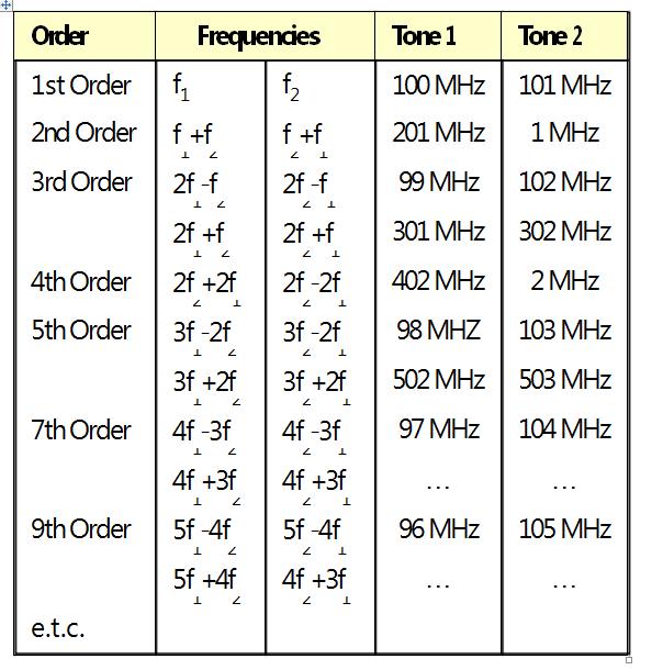
6 IM Mathematics 6
7 IM Mathematics Frequencies generated by intermodulation distortion 7
8 PIM Model In this model Is and Vt are just fitting parameters and they can be tweaked to any value until the wanted PIM is obtained. For example, Is can be used to control the power level of PIM and Vt can be used to adjust the power distribution between different order products Diode-like Model 8
9 Nonlinear Diode Effect at ferromagnetic metals A low signal operating in a linear region and a large signal operating in the non-linear region of a ferromagnetic metal is creating additional spectral components in the output signal. 9
10 PIM is a result of signal mixing at nonlinearities IM3 PIM nonlinearity increases, in theory, at a ratio of 3:1 (PIM to signal) A 1 db increase in carrier power correlates to a theoretical incre ase of 3 db in PIM signal power. In practice, the actual effect is closer to 2,3-2,5 db as the thermal noise constant -174 dbm/ Hz becomes an error contributor. 10

11 PIM are clogging up complete RF bands PIM multiplies bandwidth If bandwidth of f1 and f2 is 1 MHz then BWIM3 = 3 MHz BWIM5 = 5 MHz BWIM7 = 7 MHz 11

12 A real example - TELSTRA Next GTM UMTS 850 Example f1 = 887 MHz, 5 MHz UMTS T f2 = 935 MHz, 200 khz GSM T fim3 = 839 MHz, CDMA RX 12

13 Summary of the phenomenon PIM is of particular concern when PIM products fall in the RX band Two or more transmitter channels share a common antenna TX signal levels are high RX sensitivity is high TX and RX are diplexed 13
14 ACTIVE VS PASSIVE: Active devices require sources of energy where as passive devices do not. Active devices are non-linear and thus, the main source of intermodulation distortions and spurious emissions in RF systems. The linear passive devices that are supposed to be linear show nonlinear behavior that results in minor distortions, commonly referred to as Passive Inter Modulation (PIM) distortions. 14
15 Importance of PIM Modern systems indeed require: much tougher frequency plans, use of higher transmitter power levels more sensitive receivers, PIM manifests as an interfering signal which may degrade the performance of the receiver. 15
16 What actually causes PIM? Junctions of dissimilar materials. rust, corrosion, loose connections, dirt, oxidation, and any contamination of these factors. The result is a diode-like nonlinearity that makes an excellent mixer. As nonlinearity increases, so does the amplitude of the PIM signals. 16
17 PIM Causes Non-Linearities take two different forms Contact Non-Linearity Material Non-Linearity 17
18 PIM Causes - Contact Non-Linearities Causes of contact Non-Linearities Junction capacitance due to thin oxide layer between conductors Impurities on metal surface Semiconductor tunnel / schottky effect at point of contact Contact restistance caused by two dissimilar metals 18
19 PIM Causes - Material Non-Linearities Causes of material Non- Linearities Hysteresis effect in ferromagnetic materials (nickel, iron, steel) Thermal Heating due to p oor conduction rate (torque, corrosion, cracks) 19
20 Root Causes of PIM in a real RF environment 1- Loose and / or inconsistent 2- metal to metal contacts 3- Not enough contact pressure. 4- Cracked solder joints 5- Cold solder joints 6- Scratches or dents at mating interfaces 7- Burrs 8- Metal flakes, chips, dust 9- Improperly formed or Misaligned parts 10- Rough mating surfaces (saw cut) 11- Loose metal to metal contacts 12- Loose or rusty bolts 13- Ferromagnetic materials (steel, nickel, etc.) 14- Wind induced vibrations 1- Trapped between mating surfaces 2- Trapped between plating layers 3- Solder splatters 4- Dirt or debris 5- Surface Oxides 6- Insufficient thickness of plated metal causing RF heating 7- Too much or too little torque at 8- Contaminated conductors & Interfaces (Dirt, Dust, Moisture) 20

21 Field Examples ferromagnetic materials cracked solder joints Antenna showing oxidation within the power divider 21

22 Field Examples 22

23 Field Examples LDF4-50A RF- Repeater feeder cable 10 db Return Loss after in stallation no Repeater operation po ssible due to high noise level in Don or-site RX band 35 db Return Loss after c onnector swap 23

24 Copper Foil Copper foil is of huge influence on PIM 24
25 Very Low Profile ED Copper Foil 25

26 SEM Photo of Microstrip (C1 copper) copper debris left in at the bottom of the etched track 26

27 when designing a system, development teams will choose passive elements with minimal or acceptable levels of PIM as specified by the component manufacturer. Circulators, duplexers, and switches are particularly prone to the effect. Designers may choose to accept higher levels of passive intermodulation by selecting lower cost, smaller size, or lower performance options. Component design trade-offs, size, power, rejection, and PIM performance 27


28 The diplexer A30089 is specially designed for very low passive intermodulation and enables an improvement of your existing equipment for intermodulation measurements. The Antenna-Port includes an directional coupler to monitoring the forward and reverse power. 28
29 What other conditions affect PIM? PIM tends to increase as components age. Environments wide temperature variations, salt air polluted air, excessive vibrations 29
30 What conditions are necessary to cause PIM? two relatively strong RF signals relatively close in frequency are required to trigger PIM effects. The outputs from two or more high-power (20 W or so) transmitters are enough to create the PIM effects. The higher the power used, the greater the PIM signals generated. 30

31 How are the various signals are formed? PIM nonlinearities produce a specific frequency spectrum. 31
32 How PIM could be controlled? Avoid the use of ferrous metals. Minimize the number of contact junctions. Design all contact junctions such that they are precise and under sufficient pressure to maintain good contact. 32
33 How PIM could be controlled? Solder or cold weld all junctions where possible. Avoid dissimilar metals in direct contact. Plate all surfaces to prevent oxidation. Make certain plating is uniformly applied and of sufficient thickness. 33
34 Real world deficiencies that occur: Poor alignment of parts. Inadequately torqued screws and fasteners. Bad solder joints. Insufficient or incomplete cleaning of parts prior to plating. 34
35 Real world deficiencies that occur: Contaminated plating tanks. Plating material build-up. Using wrong materials. Poor plating adhesion. 35
36 Summary of the phenomenon PIM is measured acc. to IEC Ed RF connectors, connector cable assemblies, a nd cables intermodulation level measure ment Standard specifies the use of t wo 20 watt carriers ( 2 x +43 dbm) Typical IM3 value is -165 dbc 36
37 IEC : 2012 Passive Intermodulation Standard IEC :2012 Passive RF and microwave devices, intermodulation level measurement - Part 1: General requirements and measuring methods IEC :2012 Passive RF and microwave devices, intermodulation level measurement - Part 2: Measurement of passive intermodulation in coaxial cable assemblies IEC :2012 Passive RF and microwave devices, intermodulation level measurement - Part 3: Measurement of passive intermodulation in coaxial connectors IEC :2012 Passive RF and microwave devices, intermodulation level measurement - Part 4: Measurement of passive intermodulation in coaxial cables IEC :2013 Passive RF and microwave devices, intermodulation level measurement - Part 5: Measurement of passive intermodulation in filters IEC :2013 Passive RF and microwave devices, intermodulation level measurement - Part 6: Measurement of passive intermodulation in antennas 37
38 How is PIM Specified? Absolute power (dbm) The absolute IM power (in dbm) of intermodulation signal Relative power (dbc) IM signal power relative to the standard signal carrier Example: -110dBm IM signals generated by to +43dBM tones is a -153 dbc IM level 38
39 Test Methods when two +43 dbm carriers are injected into the device under test, i.e., -153 dbc.a typical specification requires a passive IM level no greater than 110 dbm To put this into perspective, this is a ratio of 1:2,000,000,000,000,000, or the equivalent of trying to measure the distance to the sun to an accuracy of one-tenth of a millimeter. 39
40 Realize the Necessary test Setup Rack and stack two synthesizers feeding two high power amplifiers that connect to an array of RF components. Route the signal of interest through a low noise amplifier to a spectrum analyzer. Power meter is used to set the proper transmit powers and readjust on a periodic basis to compensate for drift. Measurement results are sometimes difficult to repeat, and setups are often unstable and susceptible to damage 40
41 Example of Real Test Considering a device used in a PCS1900 Band network. Setting Carrier 1 to 1930 MHz and Carrier 2 to1990 MHz. (Note: There are some PIM test setups that, due to their design, must use one carrier set to a frequency in the receive band while the other carrier is set to a frequency in the transmit band. The validity of this approach open to debate.) The test is initiated. After the transmit frequencies and powers are established and the spectrum analyzer configured to measure the IM response, During the measurement, care is often taken not to disturb the device under test or the test setup In case instabilities might produce a data spike at the precise moment the spectrum analyzer happens to be sweeping past the IM frequency. 41
42 Dynamic Measurements IM performance is monitored during the application of an appropriate stimulus. Dynamic measurements has been given a great deal of attention with regard to cable assemblies. The concern has to do with the vulnerability of the connector /cable interface as well as IM created in the cable (by micro-cracks in solid conductor cables and discontinuous contact in braided cables) Testing involves measuring the IM as the cable is flexed and/or a bending moment is applied at the connector/cable interface. Two measurements routinely performed on all PIM critical components used,the tap test and the bending moment test. 42
43 Tap Test The tap test is simply a matter of tapping the device and watching the IM response. For example, tapping the tuning screws on filters frequently generates high levels of passive IM. After the tapping is stopped, the IM sometimes returns to its low IM condition and sometimes it remains high. The tap test has been demonstrated to be highly useful in screening devices and cables that will fail at some future time. 43

44 Dynamic IM Measurement the Strip Chart Mode of the analyzer is used to record the IM response over time. The device under test is a PCS1900 bandpass filter. What we are observing is the changing IM due to tapping. Later testing also showed this device to have much-degraded IM performance with temperature changes. 44
45 Bending Moment Test The bending moment test is performed by applying a modest side force to the connector on the device under test. If the connector is not adequately attached to the body of the component, or if the launching mechanism within the device is not solid, IM will be generated. 45
46 Swept Frequency Measurements he accepted method for measuring passive IM was to set the carrier to two fixed frequencies in the transmit band, and measure the IM generated. on many devices, this is not adequate, because these devices exhibit IM characteristics that vary as a function of frequency. The Passive IM Analyzers make this measurement at multiple frequencies practical and easy. 46
47 Swept Frequency Measurements Example A PCS1900 band duplexer with a bad connector is measured. It should be noted that the connector damage was caused by over-to rquing the connector and is undetected by visual inspection and swept return loss measurements. The comparison between The good and the bad duplexer return loss is shown in the following figure. The good duplexer meets the 115 dbm specification at all frequencies The bad duplexer has a severely degraded IM as the transmit carriers are moved from the band edges. Both duplexers would pass through QA screening if only band-edge carriers were used for the testing. To fully characterize the device under test, the swept frequency capability of the Passive IM Analyzer records the IM performance as each of the two carriers is swept in frequency across the transmit (down-link) band. Only one carrier at a time is swept, while the remaining carrier is held fixed at the band edge. 47

48 Swept Frequency Measurements Example 48
 that occur at frequencies from 1870 to 1910")
49 3 rd Order IM Response Carrier 1 is fixed at 1930 MHz Carrier 2 is swept from 1950 to 1990 MHz producing third order intermodulation products (IM3) that occur at frequencies from 1870 to 1910 MHz. 49
50 Forward and Reverse PIM Measurements Many passive RF components, like attenuators, can be utilized in both directions. Forward and reverse PIM measurements of components may display slightly different results. PIM ratings on manufacturers'data sheets should include both forward and reverse PIM characteristics. International standard for PIM measurements is IEC
51 PIM Analyzers Analyzers used by field personal are typically single port systems Dual port analyzers are used at production floors. Dual port analyzers are not to be confused with dual band PIM analyzers. What is the difference? The latter have the capability to measure two different frequency bands; the former provide two ports, one to perform reverse PIM measurements, the other for forward PM measurements 51

52 Block Diagram of Single Port & Dual Port PIM Analyzer 52
53 Block Diagram of Single Port & Dual Port PIM Analyzer RF generators which drive two high-power amplifiers (HPAs). The generated signals are variable in frequency and level. The generators can be set to any frequency in the specific band for which the PIM analyzer has been designed. An ultra low PIM combiner brings the amplified signals together and delivers the combined carriers to the Tx port of a duplexer. 53
54 Block Diagram of Single Port & Dual Port PIM Analyzer The duplexer has to provide very high separation between its wireless pages high power Tx and very low power Rx ports. As better this duplexer is designed, as better the dynamic range of the PIM test system. The output of the duplexer is basically the reverse PIM port of the PIM analyzer. 54
55 PIM Analyzers With the exception of antennas and loads, all Devices Under Test (DUTs) require external terminations to perform PIM measurements. Antennas radiate the transmitted RF power directly into the air loads convert it into heat. Any test cable and load that is used for PIM testing, must have significantly better PIM ratings than the actual DUT to allow for accurate measurements. 55
56 PIM Analyzers PIM signals that arrive at the analyzer port are channeled to the duplexer's Rx leg. The duplexer frequency correlates with the receiving band of the wireless system. Dual-port analyzers consists of all these elements, but have a second duplexer an additional internal high power, low PIM termination and a low PIM switch. 56
57 PIM Analyzers The second port feeds into the second duplexer, which has a terminated Tx port. Since an internal termination is provided, dual-port analyzers do not require external loads to terminate 2-port DUTs. The Rx port of the second duplexer measures forward PIM power. A low PIM switch toggles between reverse and forward PIM measurements. During PIM measurements, system PAs and receivers of the RF systems are disconnected and instead PIM analyzer are connected. The analyzers will now generate two high-power CW tones within the transmit band of the measured system. It is important to apply enough energy during PIM measurements to ensure the RF system is tested under conditions similar to the actual utilization. 57

58 Forward and Reverse PIM Measurement of Cable For many measurement applications single-port analyzers are suitable for both, reverse and forward PIM analysis.figure 4 shows forward and reverse PIM measurements for a simple two-terminal DUT; a cable in this example. Forward and reverse PIM will not differ much, and can easily be measured in two steps. Reverse PIM is measured by connecting one end of the DUT (A) to the PIM analyzer, while the other end is terminated with a low PIM load (B). Forward PIM is measured with the direction of the DUT reversed (B-A). The resulting PIM measurements are quite similar. 58
59 Forward & Reverse PIM Measurement of a 3 port DUT Dual-port units help measure forward and reverse PIM of components in less time. This is very beneficial for complex components with more than two ports. The example in Figure 5 shows a power splitter under test. Single-port units require three test steps, feeding the analyzer's measurement signals sequentially into the splitter ports IN, OUT1 and OUT2. Ports that are not connected to the PIM analyzer need to be terminated for accurate measurements. Dual port analyzers offer more convenient testing. During the first test step, measurement signals are fed into IN port of the splitter, while the forward port is connected to OUT1, with OUT2 59
60 Residual PIM Residual PIM is unrelated to the DUT, but it is a characteristic of the PIM analyzer. Analyzers are built with components that are far superior to the ones used in network operations PIM analyzers generate internal PIM. Even if the amount of PIM generated by these special internal components is small, it sums up and can influence the measurement. Manufacturers provide residual PIM specs in their data sheets. Residual PIM should be at least 10 db below the measurement range of the analyzer. Modern PIM analyzers use not only ultra-low PIM components, but minimize possible residual PIM readings with sophisticated DSP technology. 60
61 Which companies make PIM test equipment? Agilent Anritsu Boonton Kaelus Rosenberger Summitek Tessco. 61
62 62
63 Conclusion 63
64 Rep. ITU-R SM.2021 The following values [Petrovic and Gosling, 1979] for intermodulation performances are desirable: for single frequency transmit and receiving applications: 100 dbc for multiple frequency transmission: 130 dbc for multiple frequency transmission and reception: 143 dbc Similar considerations hold for other non-linear components like circulator, combiner, isolators, etc., installed between output stage of the amplifier and the transmitting antenna. Examples for mobile radio are given in [RA, 1987]. 64
65 fintermodulation mf1 nf2 = + where m and n are integers and ( m + n ) is the order of the intermodulation product. Part of the output spectrum of a non linear device excited by two signals f1 and f2 is shown in the following figure. How much spacing to you really need between antennas at radio sites? Robert S. Mawrey, Ph.D. Vice President of Systems and Technology 65
66 The most effective way to combat shared site radio frequency interference is to isolate nonlinear devices from strong signal sources. As illustrated in the following figure this is typically achieved using a combination of antenna isolation, filtering, and the selective use of more linear devices and ferrite isolators. Passive intermodulation can be reduced by minimizing the number of loose metallic joints2 within system components such as antennas, cables and connectors, and in the external environment on towers and wire fences. M. N. Lustgarten, COSAM (Co-site Analysis Model), IEEE Electromagnetic Compatibility Symposium Record, Anaheim, California, pp , July
67 Actual antenna spacing requirements can be estimated using comprehensive interference analysis techniques. The interference analysis should include investigation of Intermodulation and harmonics Noise Desensitization Antenna coupling Equipment characteristics Interference Mechanisms Radio frequency interference at a shared site is typically caused by one of the following mechanisms that have their origin in some form of equipment or other non-linearity: Intermodulation Transmitter Receiver Passive Out-of-band emissions Transmitter noise Transmitter spurious emissions Transmitter harmonics Receiver spurious emissions Other effects Receiver desensitization 67
68 Thank you for your attention! 68
Intermodulation Distortion in RF Connectors
 Intermodulation Distortion in RF Connectors Introduction Intermodulation distortion or IMD has always existed in RF transmission paths. Until about the early 1990 s, cellular communications had relatively
Intermodulation Distortion in RF Connectors
 a division of RF Industries Intermodulation Distortion in RF Connectors Introduction Intermodulation distortion or IMD has always existed in RF transmission paths. Until about the early 1990 s, cellular
Portable Passive Intermodulation Test Set
 Data Sheet Pim 20 Portable Passive Intermodulation Test Set Taking performance to a new peak Pim 20 - Portable Passive Intermodulation Test Set The Pim 20 is a microprocessor controlled, portable test
PIM Workshop Passive InterModulation Dublin 13/10/2015 Agenda
 PIM Workshop Passive InterModulation Dublin 13/10/2015 Agenda s Anritsu PIM Master Hands On 1 What is Intermodulation? Intermodulation distortion (IMD) is a multi-tone distortion product that results when
White Paper. PIM Test Power Levels For Mobile Communication System
 White Paper PIM Test Power Levels For Mobile Communication System Table of Content 1. Abstract 1 2. Why Do We Measure Passive Intermodulation (PIM) 2 3. The International Electro-Technical Commission (IEC)
The way of PIM3 to -150dBc
 The way of PIM3 to -150dBc 1. What is PIM? PIM is a form of passive inter-modulation distortion thatis an undesired, non-linear, signal energy generated as a bi-product of two or more carriers sharing
Advanced Test Equipment Rentals ATEC (2832)
") Established 1981 Advanced Test Equipment Rentals www.atecorp.com 800-404-ATEC (2832) Data Sheet Pim 31 Passive Intermodulation Analyzer 2 x 20W Taking performance to a new peak PIM 31 - Passive Intermodulation
Established 1981 Advanced Test Equipment Rentals www.atecorp.com 800-404-ATEC (2832) Data Sheet Pim 31 Passive Intermodulation Analyzer 2 x 20W Taking performance to a new peak PIM 31 - Passive Intermodulation
PIM Master Anritsu Field Testing PIM Solution
 PIM Master Anritsu Field Testing PIM Solution Featuring Distance-to-PIM (DTP) The Fastest Way to Pinpoint the Source of PIM Slide 1 Learning about PIM and PIM testing What is PIM? Why do we care about
MINIMIZING SITE INTERFERENCE
 MINIMIZING SITE INTERFERENCE CHAPTER 8 This chapter provides information on preventing radio frequency (RF) interference at a communications site. The following topics are included: Interference Protection
Combined Band MHz. Fig. 1 Typical Diplexer Filter Combiner Fig. 2 Typical Diplexer Combiner
 Choosing the Best Power Divider for the Task of Signal Combining As systems become more and more complex, choosing how best to combine two or more RF signals has become a far more difficult question to
Multi-function Site Passive Intermodulation Analyzer.
 Multi-function Site Passive Intermodulation Analyzer www.rosenbergerap.com 01 Introduction Rosenberger HQ, Bavaria, Germany 01 A Rosenberger Hochfrequenztechnik GmbH&Co. was founded in Germany in 1958
Demystifying PIM in today s wireless networks. By Communication Components Inc. (CCI) What is PIM?
 What is PIM?") Demystifying PIM in today s wireless networks By Communication Components Inc. (CCI) Passive Intermodulation (PIM) has become new benchmark in determining the health of a cell site. Today s mobile handset
Demystifying PIM in today s wireless networks By Communication Components Inc. (CCI) Passive Intermodulation (PIM) has become new benchmark in determining the health of a cell site. Today s mobile handset
TECHNICAL INFORMATION
 TECHNICAL INFORMATION TECHNOLOGY Y-Junction circulator PORT 1 PORT 2 PORT 3 FIG. 1 The Y-junction circulator uses spinel ferrites or garnet ferrites in the presence of a magnetic bias field, to provide
RADIO RECEIVERS ECE 3103 WIRELESS COMMUNICATION SYSTEMS
 RADIO RECEIVERS ECE 3103 WIRELESS COMMUNICATION SYSTEMS FUNCTIONS OF A RADIO RECEIVER The main functions of a radio receiver are: 1. To intercept the RF signal by using the receiver antenna 2. Select the
Understanding Mixers Terms Defined, and Measuring Performance
 Understanding Mixers Terms Defined, and Measuring Performance Mixer Terms Defined Statistical Processing Applied to Mixers Today's stringent demands for precise electronic systems place a heavy burden
WMB-7: MTT-S Workshop on Filter II: Practical Aspects of Microwave Filter Design and Realization
 WMB-7: MTT-S Workshop on Filter II: Practical Aspects of Microwave Filter Design and Realization Passive Intermodulation in Microwave Filters: Experimental Investigation Giuseppe Macchiarella (+), Alessandro
RF, Microwave & Wireless. All rights reserved
 RF, Microwave & Wireless All rights reserved 1 Non-Linearity Phenomenon All rights reserved 2 Physical causes of nonlinearity Operation under finite power-supply voltages Essential non-linear characteristics
Telegärtner Mobile Radio Base Station Components.
 Telegärtner Mobile Radio Base Station Components www.telegaertner.com Mobile Radio Base Station Components Components: Connectors EMP Protectors Jumper Cables Adaptors Tools and Accessories 2011 Telegärtner
Analysis of RF transceivers used in automotive
 Scientific Bulletin of Politehnica University Timisoara TRANSACTIONS on ELECTRONICS and COMMUNICATIONS Volume 60(74), Issue, 0 Analysis of RF transceivers used in automotive Camelia Loredana Ţeicu Abstract
2015 Interference 101. Robin Jackman Application Engineer
 2015 Interference 101 Robin Jackman Application Engineer Agenda What is Interference Introduction Definitions Spectrum Analyzer Concepts Concepts, Controls, Displays Making good measurements Measuring
2026Q CDMA/GSM Interferer MultiSource Generator
 Signal Sources 2026Q CDMA/GSM Interferer MultiSource Generator The 2026Q is designed to work with a radio test set to provide a fully integrated radio receiver test solution for cellular and PCS systems
Carrier power dependence and avoidance methods of passive intermodulation product
 International Conference on Mechatronics, Electronic, Industrial and Control Engineering (MEIC 201) Carrier power dependence and avoidance methods of passive intermodulation product Zhao Pei Wireless Theory
Cell Extender Antenna System Design Guide Lines
 Cell Extender Antenna System Design Guide Lines 1. General The design of an Antenna system for a Cell Extender site needs to take into account the following specific factors: a) The systems input and output
Keysight Technologies Innovative Passive Intermodulation (PIM) and S-parameter Measurement Solution with the ENA. Application Note
 and S-parameter Measurement Solution with the ENA. Application Note") Keysight Technologies Innovative Passive Intermodulation () and S-parameter Measurement Solution with the ENA Application Note Introduction Passive intermodulation () is a form of intermodulation distortion
Keysight Technologies Innovative Passive Intermodulation () and S-parameter Measurement Solution with the ENA Application Note Introduction Passive intermodulation () is a form of intermodulation distortion
Understanding and Troubleshooting Linear Distortions: Micro-reflections, Amplitude Ripple/Tilt and Group Delay
 Understanding and Troubleshooting Linear Distortions: Micro-reflections, Amplitude Ripple/Tilt and Group Delay RON HRANAC 1 A Clean Upstream: Or Is It? Graphic courtesy of Sunrise Telecom 2 Transmission
TETRA Tx Test Solution
 Product Introduction TETRA Tx Test Solution Signal Analyzer Reference Specifications ETSI EN 300 394-1 V3.3.1(2015-04) / Part1: Radio ETSI TS 100 392-2 V3.6.1(2013-05) / Part2: Air Interface May. 2016
Keysight Technologies Making Accurate Intermodulation Distortion Measurements with the PNA-X Network Analyzer, 10 MHz to 26.5 GHz
 Keysight Technologies Making Accurate Intermodulation Distortion Measurements with the PNA-X Network Analyzer, 10 MHz to 26.5 GHz Application Note Overview This application note describes accuracy considerations
The Schottky Diode Mixer. Application Note 995
 The Schottky Diode Mixer Application Note 995 Introduction A major application of the Schottky diode is the production of the difference frequency when two frequencies are combined or mixed in the diode.
Receiver Design. Prof. Tzong-Lin Wu EMC Laboratory Department of Electrical Engineering National Taiwan University 2011/2/21
 Receiver Design Prof. Tzong-Lin Wu EMC Laboratory Department of Electrical Engineering National Taiwan University 2011/2/21 MW & RF Design / Prof. T. -L. Wu 1 The receiver mush be very sensitive to -110dBm
High Dynamic Range Receiver Parameters
 High Dynamic Range Receiver Parameters The concept of a high-dynamic-range receiver implies more than an ability to detect, with low distortion, desired signals differing, in amplitude by as much as 90
RECEIVER MULTICOUPLER AND R.F. PRESELECTORS
 EMR corp. ELECTROMAGNETIC DESIGNS AND CONSULTING SERVICES FOR THE TWO-WAY COMMUNICATIONS INDUSTRY 22402 N. 19th Avenue - Phoenix, Arizona 85027 Toll Free: 1-800-796-2875 Tel: (623) 581-2875 Fax: (623)
Objectives Typical IMD Levels and Applications Emission Monitoring Solutions Measuring without Disrupting
 Objectives Typical IMD Levels and Applications Emission Monitoring Solutions Measuring without Disrupting Low PIM Filtering Solutions - Building Blocks for Reducing Uncertainty of Measurement High-Pass/Low-Pass
Analog Devices Welcomes Hittite Microwave Corporation NO CONTENT ON THE ATTACHED DOCUMENT HAS CHANGED
 Analog Devices Welcomes Hittite Microwave Corporation NO CONTENT ON THE ATTACHED DOCUMENT HAS CHANGED www.analog.com www.hittite.com THIS PAGE INTENTIONALLY LEFT BLANK v01.05.00 HMC141/142 MIXER OPERATION
Measurements 2: Network Analysis
 Measurements 2: Network Analysis Fritz Caspers CAS, Aarhus, June 2010 Contents Scalar network analysis Vector network analysis Early concepts Modern instrumentation Calibration methods Time domain (synthetic
Analog Devices Welcomes Hittite Microwave Corporation NO CONTENT ON THE ATTACHED DOCUMENT HAS CHANGED
 Analog Devices Welcomes Hittite Microwave Corporation NO CONTENT ON THE ATTACHED DOCUMENT HAS CHANGED www.analog.com www.hittite.com THIS PAGE INTENTIONALLY LEFT BLANK 17 Product Application Notes Introduction
Ultra High Frequency Measurements
 Ultra High Frequency Measurements Desmond Fraser desmond@rheintech.com 703.689.0368 360 Herndon Parkway Suite 1400 Herndon, VA 20170 IEEE EMC DC / N. VA Chapter 31 January 2012 Overview We ll review Millimeter
TSEK38 Radio Frequency Transceiver Design: Project work B
 TSEK38 Project Work: Task specification A 1(15) TSEK38 Radio Frequency Transceiver Design: Project work B Course home page: Course responsible: http://www.isy.liu.se/en/edu/kurs/tsek38/ Ted Johansson (ted.johansson@liu.se)
Understanding RF and Microwave Analysis Basics
 Understanding RF and Microwave Analysis Basics Kimberly Cassacia Product Line Brand Manager Keysight Technologies Agenda µw Analysis Basics Page 2 RF Signal Analyzer Overview & Basic Settings Overview
ELEN 701 RF & Microwave Systems Engineering. Lecture 8 November 8, 2006 Dr. Michael Thorburn Santa Clara University
 ELEN 701 RF & Microwave Systems Engineering Lecture 8 November 8, 2006 Dr. Michael Thorburn Santa Clara University System Noise Figure Signal S1 Noise N1 GAIN = G Signal G x S1 Noise G x (N1+No) Self Noise
Keysight Technologies Pulsed Antenna Measurements Using PNA Network Analyzers
 Keysight Technologies Pulsed Antenna Measurements Using PNA Network Analyzers White Paper Abstract This paper presents advances in the instrumentation techniques that can be used for the measurement and
Agilent 8360B/8360L Series Synthesized Swept Signal/CW Generators 10 MHz to 110 GHz
 Agilent 8360B/8360L Series Synthesized Swept Signal/CW Generators 10 MHz to 110 GHz ity. l i t a ers V. n isio c e r P. y t i l i ib Flex 2 Agilent 8360 Synthesized Swept Signal and CW Generator Family
CAVITY TUNING. July written by Gary Moore Telewave, Inc. 660 Giguere Court, San Jose, CA Phone:
 CAVITY TUNING July 2017 -written by Gary Moore Telewave, Inc 660 Giguere Court, San Jose, CA 95133 Phone: 408-929-4400 1 P a g e Introduction Resonant coaxial cavities are the building blocks of modern
Technical keys to successful network modernization: PIM
 White paper Technical keys to successful network modernization: PIM Ensure you achieve your modernization goals by focusing on these four areas Lou Meyer, director, applications engineering base station
FERRITE DEVICES CONTENTS CIRCULATORS & ISOLATORS SPECIFIC REQUEST TECHNICAL INFORMATION DROP-IN CIRCULATORS & ISOLATORS...
 FERRITE DEVICES CONTENTS PAGE CIRCULATORS & ISOLATORS SPECIFIC REQUEST........................ 75 TECHNICAL INFORMATION...................................................... 76 DROP-IN CIRCULATORS & ISOLATORS......................................
RF/IF Terminology and Specs
 RF/IF Terminology and Specs Contributors: Brad Brannon John Greichen Leo McHugh Eamon Nash Eberhard Brunner 1 Terminology LNA - Low-Noise Amplifier. A specialized amplifier to boost the very small received
Improving Amplitude Accuracy with Next-Generation Signal Generators
 Improving Amplitude Accuracy with Next-Generation Signal Generators Generate True Performance Signal generators offer precise and highly stable test signals for a variety of components and systems test
Termination Insensitive Mixers By Howard Hausman President/CEO, MITEQ, Inc. 100 Davids Drive Hauppauge, NY
 Termination Insensitive Mixers By Howard Hausman President/CEO, MITEQ, Inc. 100 Davids Drive Hauppauge, NY 11788 hhausman@miteq.com Abstract Microwave mixers are non-linear devices that are used to translate
Noise and Interference Limited Systems
 Chapter 3 Noise and Interference Limited Systems 47 Basics of link budgets Link budgets show how different components and propagation processes influence the available SNR Link budgets can be used to compute
SIGNAL GENERATORS. MG3633A 10 khz to 2700 MHz SYNTHESIZED SIGNAL GENERATOR GPIB
 SYNTHESIZED SIGNAL GENERATOR MG3633A GPIB For Evaluating of Quasi-Microwaves and Measuring High-Performance Receivers The MG3633A has excellent resolution, switching speed, signal purity, and a high output
Receiver Architecture
 Receiver Architecture Receiver basics Channel selection why not at RF? BPF first or LNA first? Direct digitization of RF signal Receiver architectures Sub-sampling receiver noise problem Heterodyne receiver
Hot S 22 and Hot K-factor Measurements
 Application Note Hot S 22 and Hot K-factor Measurements Scorpion db S Parameter Smith Chart.5 2 1 Normal S 22.2 Normal S 22 5 0 Hot S 22 Hot S 22 -.2-5 875 MHz 975 MHz -.5-2 To Receiver -.1 DUT Main Drive
Interference Analysis and Spectrum Monitor Seminar
 Interference Analysis and Spectrum Monitor Seminar Handheld RF & Microwave Instruments Andrew Benn Business Development Manager Agilent Technologies Wednesday 12 th October 2011 1 Agilent Technologies,
Satellite Communications Testing
 Satellite Communications Testing SATELLITE COMMUNICATIONS TESTING Traditionally, the satellite industry has relied on geosynchronous earth orbit (GEO) satellites that take years to build and require very
Signal Sources. 2026Q CDMA Interferer Multisource Generator. Advanced Test Equipment Rentals ATEC (2832)
") Signal Sources Established 1981 Advanced Test Equipment Rentals www.atecorp.com 800-404-ATEC (2832) 2026Q CDMA Interferer Multisource Generator The 2026Q is designed to work with a radio test set to provide
Signal Sources Established 1981 Advanced Test Equipment Rentals www.atecorp.com 800-404-ATEC (2832) 2026Q CDMA Interferer Multisource Generator The 2026Q is designed to work with a radio test set to provide
Combining filters and self-interference cancellation for mixer-first receivers in Full Duplex and Frequency-Division Duplex transceiver systems
 Combining filters and self-interference cancellation for mixer-first receivers in Full Duplex and Frequency-Division Duplex transceiver systems Gert-Jan Groot Wassink, bachelor student Electrical Engineering
Ultra Wideband Indoor Radio Channel Measurements
 Ultra Wideband Indoor Radio Channel Measurements Matti Hämäläinen, Timo Pätsi, Veikko Hovinen Centre for Wireless Communications P.O.Box 4500 FIN-90014 University of Oulu, FINLAND email: matti.hamalainen@ee.oulu.fi
SC5307A/SC5308A 100 khz to 6 GHz RF Downconverter. Datasheet SignalCore, Inc.
 SC5307A/SC5308A 100 khz to 6 GHz RF Downconverter Datasheet 2017 SignalCore, Inc. support@signalcore.com P RODUCT S PECIFICATIONS Definition of Terms The following terms are used throughout this datasheet
RF System Aspects for SDR. A Tutorial. Dr. Ruediger Leschhorn, Rohde & Schwarz 29. November 2011
 RF System Aspects for SDR A Tutorial Dr. Ruediger Leschhorn, Rohde & Schwarz 29. November 2011 Content Radio System Some Basics Link Budget Cosite Examples Desensitization Blocking, Transmitter Noise,
Agilent Technologies PSA Series Spectrum Analyzers Test and Adjustment Software
 Test System Overview Agilent Technologies PSA Series Spectrum Analyzers Test and Adjustment Software Test System Overview The Agilent Technologies test system is designed to verify the performance of the
MITIGATING INTERFERENCE ON AN OUTDOOR RANGE
 MITIGATING INTERFERENCE ON AN OUTDOOR RANGE Roger Dygert MI Technologies Suwanee, GA 30024 rdygert@mi-technologies.com ABSTRACT Making measurements on an outdoor range can be challenging for many reasons,
A Guide to Calibrating Your Spectrum Analyzer
 A Guide to Calibrating Your Application Note Introduction As a technician or engineer who works with electronics, you rely on your spectrum analyzer to verify that the devices you design, manufacture,
Product quality is the life of CenRF CenRF Communications Limited
 Product quality is the life of CenRF Contents Company Introduction Professional Team High Quality Products Product Application Company Introduction Hangzhou Shengtong Technology Co., Ltd. (), is a professional
Low Cost Mixer for the 10.7 to 12.8 GHz Direct Broadcast Satellite Market
 Low Cost Mixer for the.7 to 12.8 GHz Direct Broadcast Satellite Market Application Note 1136 Introduction The wide bandwidth requirement in DBS satellite applications places a big performance demand on
Return Loss Bridge Basics
 1.0 Introduction Return loss bridges have many useful applications for the two-way radio technician These bridges are particularly helpful when used with the tracking generator feature of many service
Keysight Technologies PNA-X Series Microwave Network Analyzers
 Keysight Technologies PNA-X Series Microwave Network Analyzers Active-Device Characterization in Pulsed Operation Using the PNA-X Application Note Introduction Vector network analyzers (VNA) are the common
FREQUENCY AGILE FM MODULATOR INSTRUCTION BOOK IB
 FMT615C FREQUENCY AGILE FM MODULATOR INSTRUCTION BOOK IB1215-02 TABLE OF CONTENTS SECTION SUBJECT 1.0 Introduction 2.0 Installation & Operating Instructions 3.0 Specification 4.0 Functional Description
HP Archive. This vintage Hewlett Packard document was preserved and distributed by www. hparchive.com Please visit us on the web!
 HP Archive This vintage Hewlett Packard document was preserved and distributed by www. hparchive.com Please visit us on the web! On-line curator: Glenn Robb This document is for FREE distribution only!
A Method for Gain over Temperature Measurements Using Two Hot Noise Sources
 A Method for Gain over Temperature Measurements Using Two Hot Noise Sources Vince Rodriguez and Charles Osborne MI Technologies: Suwanee, 30024 GA, USA vrodriguez@mitechnologies.com Abstract P Gain over
Vector Network Analyzer
 Vector Network Analyzer VNA Basics VNA Roadshow Budapest 17/05/2016 Content Why Users Need VNAs VNA Terminology System Architecture Key Components Basic Measurements Calibration Methods Accuracy and Uncertainty
Session 3. CMOS RF IC Design Principles
 Session 3 CMOS RF IC Design Principles Session Delivered by: D. Varun 1 Session Topics Standards RF wireless communications Multi standard RF transceivers RF front end architectures Frequency down conversion
Keysight Technologies Techniques for Precise Cable and Antenna Measurements in the Field
 Keysight Technologies Techniques for Precise Cable and Antenna Measurements in the Field Using FieldFox handheld analyzers Application Note This application note introduces the practical aspects of cable
DMR Rx Test Solution. Signal Analyzer MS2830A. Reference Specifications
 Product Introduction DMR Rx Test Solution Signal Analyzer MS2830A Reference Specifications ETSI EN 300 113 Version 2.1.1 (2016-08) / Technical characteristics of the receiver ETSI TS 102 361-1 Version
DMR Tx Test Solution. Signal Analyzer MS2830A. Reference Specifications
 Product Introduction DMR Tx Test Solution Signal Analyzer MS2830A Reference Specifications ETSI EN 300 113 Version 2.1.1 (2016-08) / Technical characteristics of the transmitter ETSI TS 102 361-1 Version
A Simplified Extension of X-parameters to Describe Memory Effects for Wideband Modulated Signals
 Jan Verspecht bvba Mechelstraat 17 B-1745 Opwijk Belgium email: contact@janverspecht.com web: http://www.janverspecht.com A Simplified Extension of X-parameters to Describe Memory Effects for Wideband
AN X-BAND FREQUENCY AGILE SOURCE WITH EXTREMELY LOW PHASE NOISE FOR DOPPLER RADAR
 AN X-BAND FREQUENCY AGILE SOURCE WITH EXTREMELY LOW PHASE NOISE FOR DOPPLER RADAR H. McPherson Presented at IEE Conference Radar 92, Brighton, Spectral Line Systems Ltd England, UK., October 1992. Pages
ETSI ES V1.1.1 ( )
") ES 202 056 V1.1.1 (2005-01) Standard Electromagnetic compatibility and Radio spectrum Matters (ERM); Active antennas used for broadcast TV and sound reception from 47 MHz to 860 MHz 2 ES 202 056 V1.1.1
ES 202 056 V1.1.1 (2005-01) Standard Electromagnetic compatibility and Radio spectrum Matters (ERM); Active antennas used for broadcast TV and sound reception from 47 MHz to 860 MHz 2 ES 202 056 V1.1.1
TELEMETRY RE-RADIATION SYSTEM
 TELEMETRY RE-RADIATION SYSTEM Paul Cook, Director, Missile Systems Teletronics Technology Corporation, Newtown, PA USA Louis Natale, F-22 Instrumentation Sr. Staff Engineer Lockheed Martin Aeronautics
Precision Test & Measurement Solutions by CCI
 Precision Test & Measurement Solutions by CCI Passive Intermodulation...challenging the technology of today s wireless communication systems Passive Intermodulation (PIM) is an undesired, non-linear, signal
SC5407A/SC5408A 100 khz to 6 GHz RF Upconverter. Datasheet. Rev SignalCore, Inc.
 SC5407A/SC5408A 100 khz to 6 GHz RF Upconverter Datasheet Rev 1.2 2017 SignalCore, Inc. support@signalcore.com P R O D U C T S P E C I F I C A T I O N S Definition of Terms The following terms are used
900 MHz Antenna Sharing Combiner ASC900VG11A
 DATA SHEET Small, lightweight, outdoor unit Dual Technology Combiner (GSM 900 / UMTS 900) Can also be used for same technology (e.g. GSM/GSM) Can be used close to Antenna Can be used in Ground Based Applications
Co-existence. DECT/CAT-iq vs. other wireless technologies from a HW perspective
 Co-existence DECT/CAT-iq vs. other wireless technologies from a HW perspective Abstract: This White Paper addresses three different co-existence issues (blocking, sideband interference, and inter-modulation)
Agilent AN 1275 Automatic Frequency Settling Time Measurement Speeds Time-to-Market for RF Designs
 Agilent AN 1275 Automatic Frequency Settling Time Measurement Speeds Time-to-Market for RF Designs Application Note Fast, accurate synthesizer switching and settling are key performance requirements in
850 MHz Antenna Sharing Combiner ASC850VG12A
 DATA SHEET Small, lightweight, outdoor unit Dual Technology Combiner (GSM 850 / UMTS 850) Can also be used for same technology (e.g. GSM/GSM) Can be used close to Antenna Can be used in Ground Based Applications
PA FAN PLATE ASSEMBLY 188D6127G1 SYMBOL PART NO. DESCRIPTION. 4 SBS /10 Spring nut. 5 19A702339P510 Screw, thread forming, flat head.
 MAINTENANCE MANUAL 851-870 MHz, 110 WATT POWER AMPLIFIER 19D902797G5 TABLE OF CONTENTS Page DESCRIPTION.............................................. Front Page SPECIFICATIONS.................................................
The 144MHz Anglian 3 transverter
 The 144MHz Anglian 3 transverter A high performance 144/28MHz transverter G4DDK document issue 1 12/9/16 Introduction Anglian 3 is an update to the 144MHz Anglian 2 transverter. The Anglian 2 is no longer
Development of high cost performance signal analyzer MS2830A -044/045
 Development of high cost performance signal analyzer MS2830A -044/045 Yuji Kishi, Shuichi Matsuda, Koichiro Tomisaki, Kozo Yokoyama, Yoshiaki Yasuda, Tsukasa Yasui, Kota Kuramitsu [Summary] We have developed
 HF Receiver Testing: Issues & Advances (also presented at APDXC 2014, Osaka, Japan, November 2014) Adam Farson VA7OJ Copyright 2014 North Shore Amateur Radio Club NSARC HF Operators HF RX Testing 1 HF
Module 8 Theory. dbs AM Detector Ring Modulator Receiver Chain. Functional Blocks Parameters. IRTS Region 4
 Module 8 Theory dbs AM Detector Ring Modulator Receiver Chain Functional Blocks Parameters Decibel (db) The term db or decibel is a relative unit of measurement used frequently in electronic communications
PXI-based Radio Communications Testing. Reduce the size of your test bench at the same time you reduce cost while facilitating seamless automation.
 PXI-based Radio Communications Testing Reduce the size of your test bench at the same time you reduce cost while facilitating seamless automation. Introduction General radio communications testing often
Francis J. Smith CTO Finesse Wireless Inc.
 Impact of the Interference from Intermodulation Products on the Load Factor and Capacity of Cellular CDMA2000 and WCDMA Systems & Mitigation with Interference Suppression White Paper Francis J. Smith CTO
REDUTELCO TECHNOLOGY CO.,LTD.
 User Manual Wide Tri Band Booster (23dBm) REDUTELCO TECHNOLOGY CO.,LTD. 2013 January Information in this manual is subject to change without notice http:www.redutelco.com 2009 Redutelco All rights reserved
Multitone Harmonic Radar
 8//03 Multitone Harmonic Radar Gregory J. Mazzaro & Anthony F. Martone U.S. Army Research Laboratory Adelphi, MD SPIE DSS 03 pre-recorded 03-04-4 Presentation Overview Introduction to Nonlinear Radar Nonlinearity
THE BASICS OF RADIO SYSTEM DESIGN
 THE BASICS OF RADIO SYSTEM DESIGN Mark Hunter * Abstract This paper is intended to give an overview of the design of radio transceivers to the engineer new to the field. It is shown how the requirements
IMPACT OF POWER VARIATION ON 3RD ORDER PASSIVE INTERMODULATION OF COAXIAL RF-CABLES AND THEIR CONNECTORS
 IMPACT OF POWER VARIATION ON 3RD ORDER PASSIVE INTERMODULATION OF COAXIAL RF-CABLES AND THEIR CONNECTORS Hartmut Gohdes RFS kabelmetal, Division of kabelmetal electro GmbH, D-30179 Hannover, Germany Abstract
Cavity Filters & Duplexers
 Cavity Filters & Duplexers Cavity Filters Introduction & Construction Cavity Filters Resonant cavity filters are the primary building blocks of duplexers, multicouplers and preselectors. However, their
6.976 High Speed Communication Circuits and Systems Lecture 20 Performance Measures of Wireless Communication
 6.976 High Speed Communication Circuits and Systems Lecture 20 Performance Measures of Wireless Communication Michael Perrott Massachusetts Institute of Technology Copyright 2003 by Michael H. Perrott
ENGINEERING COMMITTEE Interface Practices Subcommittee AMERICAN NATIONAL STANDARD ANSI/SCTE
 ENGINEERING COMMITTEE Interface Practices Subcommittee AMERICAN NATIONAL STANDARD ANSI/SCTE 145 2013 Test Method for Second Harmonic Distortion of ives Using a Single Carrier NOTICE The Society of Cable
5G and mmwave Testing
 5G and mmwave Testing 5G and mmwave Testing The development and deployment of 5G technology is changing the way wireless carriers and internet service providers think about meeting the ever increasing
CIRCULATOR APPLICATION NOTE ANV001.
 APPLICATION NOTE ANV001 Bötelkamp 31, D-22529 Hamburg, GERMANY Phone: +49-40 547 544 60 Fax: +49-40 547 544 666 Email: info@valvo.com A Circulator is defined as a non-reciprocal, passive three ports, ferromagnetic
Maintenance Manual LBI-38531G MHz, 110 WATT POWER AMPLIFIER 19D902797G1 DESCRIPTION TABLE OF CONTENTS
 Maintenance Manual LBI-38531G 136-174 MHz, 110 WATT POWER AMPLIFIER 19D902797G1 TABLE OF CONTENTS Page DESCRIPTION.............................................. Front Cover SPECIFICATIONS.................................................