PIM Workshop Passive InterModulation Dublin 13/10/2015 Agenda
|
|
|
- Dylan Carpenter
- 5 years ago
- Views:
Transcription
1 PIM Workshop Passive InterModulation Dublin 13/10/2015 Agenda s Anritsu PIM Master Hands On 1
 is a multi-tone distortion product that results when two or more signals are")
2 What is Intermodulation? Intermodulation distortion (IMD) is a multi-tone distortion product that results when two or more signals are present at the input of a non-linear device. Intermodulation is caused by non-linear behavior 2


3 Linear/Non Linear Device Linear device: A device for which the output is, within a given dynamic range, linearly proportional to the input Non Linear device: Introducing frequencies Active/Passive Device An active component must be biased (Amplifier) A passive device does not require a source of energy for its operation 3
4 Ideal Infrastructure Non-Ideal Infrastructure 4
5 What are the mixing products created by PIM? IM n+m = n*f1 m*f2 IM n+m = n*f2 m*f1 (low side) (high side) IM3, 3rd order is the strongest product IM 3 = 2*F1 F2 IM 3 = F2 2*F1 (low side) (high side) EU Bands Rx Tx 800 (20) E-GSM Case F1 * 925 F2 * (R/T) (8) (3) (1) (7) rd 3rd 5th 5th 7th 7th
6 EU Bands Rx Tx DCS Case F1 * 1805 F2 * (20) (R/T) (8) (3) (1) (7) rd 3rd 5th 5th 7th 7th EU Bands Rx Tx UMTS Band I Case F1 * 2110 F2 * (20) (R/T) (8) (3) (1) (7) rd 3rd 5th 5th 7th 7th
7 Is PIM frequency dependent? NO! Value of PIM will change, but PIM effect stays Is PIM power dependent? YES! As the transmitter power increases, the importance of PIM on the overall system performance becomes of increasing concern Bandwidth of mixing products F1 * 1930 F2 * rd 3rd 5th 5th 7th 7th 7x 5x 3x 1x 1x 3x 5x 7x


8 PIM Amplitude: dbm or dbc PIM Amplitude: dbm VS Watts 8
9 PIM Load A 50 Ohm termination designed to produce very little or no PIM. Used to replace an antenna when testing the cable at a site PIM Source A 50 Ohm device designed to produce a known amount of PIM. Used to check the PIM Test Set Shall we sweep the line or PIM test it? Sweep test measures efficiency of signal propagation. PIM test measures ability to propagate signals without generating interference. Both tests are important and necessary to ensure quality site construction. 9
10 !! PIM is not the same as VSWR and Return Loss!! Return Loss (or VSWR) Measures: Impedance Mismatch vs. Frequency DTF (Distance to Fault) Measures : Impedance Mismatch vs. Distance These are all essential measurements of cables/antennas, but the they don y don t measure PIM PIM Measures: Non-Linearity and Loose Connections DTP (Distance To PIM) Measures: PIM Location Environmental Diodes, what? Name used for elements outside the BTS in the nearby environment that are acting like diodes in mixing signals. This due to physical properties of materials Corroded objects are one of the main problems," Rusty Bolt Effect 10
11 Where is my PIM? A US mobile operator says that 50% of their network PIM problems are not related to the base stations Anritsu Distance-to-PIM can tell you HSDPA Peak Data (Physical Layer) vs. C/I or E c /N t Downlink Peak Data rate (Mbps) C/I or E c /N t (db) PIM looks like interference to the system, lowering the C/I ratio and the data rate Source: Qualcomm, HSDPA for Improved Downlink Data Transfer, Oct
12 Indicators of PIM Problems Case 1 PIM often shows up as poor statistics from the affected sector One of the first and most direct indications of PIM can be seen in cells with two receive paths. If the noise floor is not equal between the two paths, the cause is likely PIM generated inside the noisy receive path Indicators of PIM Problems Case 2 If a cell site performs poorly when dry conditions exist but improves dramatically when a rainstorm passes through the region, the technician should immediately inspect the surrounding area for items that have rusty mounts 12


13 Causes of PIM - 1 Mechanical Considerations Metallic Contact Tunneling Effects Rusty Bolt Effect Fritting Ferromagnetic Materials such as iron, nickel, cobalt, and some alloys of magnesium, aluminum and copper Causes of PIM - 2 Connectors Poor connector attachment causes electrical Arcing Arcing creates serious interferences Types of poor connectors attachment Loose connector body Improper soldering of center Pin Recessed center Pin Cable cut at an angle Rough hacksaw cut 13


14 Causes of PIM - 3 Connectors/Cables Termination Loose Mating of connectors Should be tightened to spec Sometimes loosened by installer to achieve RL spec Over tightened connectors Causes center contact to fracture or bend Sometimes over-tightened by installer to achieve RL spec Poor weatherproofing Water in cable causing corrosion Dirty connectors/cables Use alcohol swabs Causes of PIM - 4 Manufacturing Defects in: Cables Bad weld in cable sheath Missing foam inside cable Antennas Internal failures Other Passive Devices Directional couplers Diplexers Lightning protectors 14


15 Causes of PIM - 5 Adapters Use quality adapters Test them to be sure they have low PIM Discard adapters with high PIM Clean with denatured Alcohol Adapters are for testing Should never ne in-circuit when actually providing service Keep them clean! Causes of PIM - 5 Cable bent near connector A bend close to connector can cause PIM Some antennas have poorly placed connectors, the connector is obstructed by the mounting pipe This difficult access results in a bend near the connector The minimum distance between the connector and the first bend should be two fist widths or more Observe the manufacturer s minimum bend radius, excessive bend pull the center conductor out the connector 15
16 Safety PIM Test Sets generate 80 Watts of RF Power (2 x 40 W). This amount of power is required to find PIM Problems and is safe when the cable is terminated with a Load This amount of power may be unsafe when applied to an antenna that has a person close by. 16


17 Things NOT TO DO Things NOT TO DO 17

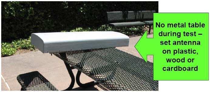
18 Things NOT TO DO Things NOT TO DO 18

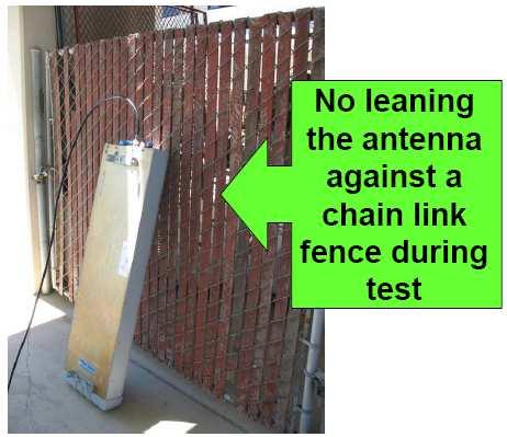
19 Things NOT TO DO Things NOT TO DO 19

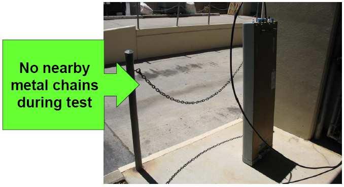
20 Things NOT TO DO Things NOT TO DO 20

21 The right way to do it Troubleshooting Guide 1. Start with VSWR and DTF if needed to check transmission 2. PIM test the cable with the antenna connected, 2x40W 3. If PIM fails, use DTP to locate hot spots Establish location of the antenna by connecting a PIM Standard after the cable You can then see if PIM is caused by external sources 4. Remember to tap (dynamic) test all Hot Spots as well as the Lightning Protector, Current Injector (Bias Tee), Connectors and ground at attachment points 5. Correct any PIM Hot Spots 6. If nearby objects (rusty objects near antenna) are causing PIM failure, report these to the antenna owner for resolution 21
22 PIM Limits Antennas that were installed 10 years ago were probably not manufactured with PIM performance in mind, so it would be unrealistic to set a PIM level greater than -80 dbm because very few would measure favorably A standard figure used around the world is a pass level of -97 dbm With the overlay of LTE services now beginning, a pass value of -97 dbm may not be enough, and it would be wise to achieve the specified receiver sensitivity level (usually around -107 dbm) with PIM testing 22
PIM Master Anritsu Field Testing PIM Solution
 PIM Master Anritsu Field Testing PIM Solution Featuring Distance-to-PIM (DTP) The Fastest Way to Pinpoint the Source of PIM Slide 1 Learning about PIM and PIM testing What is PIM? Why do we care about
The way of PIM3 to -150dBc
 The way of PIM3 to -150dBc 1. What is PIM? PIM is a form of passive inter-modulation distortion thatis an undesired, non-linear, signal energy generated as a bi-product of two or more carriers sharing
White Paper. PIM Test Power Levels For Mobile Communication System
 White Paper PIM Test Power Levels For Mobile Communication System Table of Content 1. Abstract 1 2. Why Do We Measure Passive Intermodulation (PIM) 2 3. The International Electro-Technical Commission (IEC)
Intermodulation Distortion in RF Connectors
 Intermodulation Distortion in RF Connectors Introduction Intermodulation distortion or IMD has always existed in RF transmission paths. Until about the early 1990 s, cellular communications had relatively
Advanced Test Equipment Rentals ATEC (2832)
") Established 1981 Advanced Test Equipment Rentals www.atecorp.com 800-404-ATEC (2832) Data Sheet Pim 31 Passive Intermodulation Analyzer 2 x 20W Taking performance to a new peak PIM 31 - Passive Intermodulation
Established 1981 Advanced Test Equipment Rentals www.atecorp.com 800-404-ATEC (2832) Data Sheet Pim 31 Passive Intermodulation Analyzer 2 x 20W Taking performance to a new peak PIM 31 - Passive Intermodulation
Intermodulation Distortion in RF Connectors
 a division of RF Industries Intermodulation Distortion in RF Connectors Introduction Intermodulation distortion or IMD has always existed in RF transmission paths. Until about the early 1990 s, cellular
Passive Intermodulation(PIM)
") Passive Intermodulation(PIM) Causes of PIM in the Passive Equipment`s such as FM, VHF, UHF Antenna and What does a field technician need to fix a PIM problem?- By Asghar Bahrani Desember 12,13, 2017 1
Passive Intermodulation(PIM) Causes of PIM in the Passive Equipment`s such as FM, VHF, UHF Antenna and What does a field technician need to fix a PIM problem?- By Asghar Bahrani Desember 12,13, 2017 1
Demystifying PIM in today s wireless networks. By Communication Components Inc. (CCI) What is PIM?
 What is PIM?") Demystifying PIM in today s wireless networks By Communication Components Inc. (CCI) Passive Intermodulation (PIM) has become new benchmark in determining the health of a cell site. Today s mobile handset
Demystifying PIM in today s wireless networks By Communication Components Inc. (CCI) Passive Intermodulation (PIM) has become new benchmark in determining the health of a cell site. Today s mobile handset
Telegärtner Mobile Radio Base Station Components.
 Telegärtner Mobile Radio Base Station Components www.telegaertner.com Mobile Radio Base Station Components Components: Connectors EMP Protectors Jumper Cables Adaptors Tools and Accessories 2011 Telegärtner
Demo / Application Guide for DSA815(-TG) / DSA1000 Series
 / DSA1000 Series") Demo / Application Guide for DSA815(-TG) / DSA1000 Series TX1000 Mobile Phone Frontend Mixer Bandpass Filter PA The schematic above shows a typical front end of a mobile phone. Our TX1000 RF Demo Kit shows
Demo / Application Guide for DSA815(-TG) / DSA1000 Series TX1000 Mobile Phone Frontend Mixer Bandpass Filter PA The schematic above shows a typical front end of a mobile phone. Our TX1000 RF Demo Kit shows
Multi-function Site Passive Intermodulation Analyzer.
 Multi-function Site Passive Intermodulation Analyzer www.rosenbergerap.com 01 Introduction Rosenberger HQ, Bavaria, Germany 01 A Rosenberger Hochfrequenztechnik GmbH&Co. was founded in Germany in 1958
Portable Passive Intermodulation Test Set
 Data Sheet Pim 20 Portable Passive Intermodulation Test Set Taking performance to a new peak Pim 20 - Portable Passive Intermodulation Test Set The Pim 20 is a microprocessor controlled, portable test
Understanding and Troubleshooting Linear Distortions: Micro-reflections, Amplitude Ripple/Tilt and Group Delay
 Understanding and Troubleshooting Linear Distortions: Micro-reflections, Amplitude Ripple/Tilt and Group Delay RON HRANAC 1 A Clean Upstream: Or Is It? Graphic courtesy of Sunrise Telecom 2 Transmission
Precision Test & Measurement Solutions by CCI
 Precision Test & Measurement Solutions by CCI Passive Intermodulation...challenging the technology of today s wireless communication systems Passive Intermodulation (PIM) is an undesired, non-linear, signal
LTE Signal Quality Analysis. BTS Master, Cell Master,, Spectrum Master
 LTE Signal Quality Analysis BTS Master, Cell Master,, Spectrum Master Slide 1 Anritsu LTE Test Instrument Portfolio Signaling Tester Fading Simulator Signal Analyzers Vector Signal Generator Radio Communication
Quick Site Testing with the 8800SX
 Quick Site Testing with the 8800SX Site Testing with the 8800SX Basic Tests 5 site testing involves several tests to verify site operation. NOTE: This is not intended to be a complete commissioning procedure.
TECHNICAL INFORMATION
 TECHNICAL INFORMATION TECHNOLOGY Y-Junction circulator PORT 1 PORT 2 PORT 3 FIG. 1 The Y-junction circulator uses spinel ferrites or garnet ferrites in the presence of a magnetic bias field, to provide
FERRITE DEVICES CONTENTS CIRCULATORS & ISOLATORS SPECIFIC REQUEST TECHNICAL INFORMATION DROP-IN CIRCULATORS & ISOLATORS...
 FERRITE DEVICES CONTENTS PAGE CIRCULATORS & ISOLATORS SPECIFIC REQUEST........................ 75 TECHNICAL INFORMATION...................................................... 76 DROP-IN CIRCULATORS & ISOLATORS......................................
Technical Manual. Mobile Communication Mini Booster Model: PW-MB or PW-MB10-900
 Technical Manual Mobile Communication Mini Booster Model: PW-MB10-800 or PW-MB10-900 PW-MB10-2100 or PW-MB10-1800 Page 1 Table of Contents Introduction Name & Function How to install the system User Attentions
900 MHz Antenna Sharing Combiner ASC900VG11A
 DATA SHEET Small, lightweight, outdoor unit Dual Technology Combiner (GSM 900 / UMTS 900) Can also be used for same technology (e.g. GSM/GSM) Can be used close to Antenna Can be used in Ground Based Applications
850 MHz Antenna Sharing Combiner ASC850VG12A
 DATA SHEET Small, lightweight, outdoor unit Dual Technology Combiner (GSM 850 / UMTS 850) Can also be used for same technology (e.g. GSM/GSM) Can be used close to Antenna Can be used in Ground Based Applications
AWS Antenna Sharing Combiner
 DATA SHEET Small, lightweight, outdoor unit Multi-Technology Combiner (GSM/UMTS/CDMA/LTE AWS Band) Can also be used for same technology (e.g. UMTS/UMTS or LTE/LTE) Can be used close to Antenna Can be used
ATSBT-BOTTOM-FM-4G. Electrical Specifications. Product Classification. General Specifications. Mechanical Specifications. Bottom Smart Bias Tee
 Electrical Specifications EU Certification Bottom Smart Bias Tee Injects AISG power and control signals onto a coaxial cable line Reduces cable and site lease costs by eliminating the need for AISG home
Revision 1.b Release Date July 29, 2007 This data sheet covers models 4379, 4472 Revision Notes Repl 0.d (Rev p/n 250W, B version of Comb)
") Part Number Revision 1.b Release Date July 29, 2007 This data sheet covers models 4379, 4472 Revision Notes Repl 0.d (Rev p/n 250W, B version of Comb) Amplifier Name Technical Specifications Summary Frequency
Part Number Revision 1.b Release Date July 29, 2007 This data sheet covers models 4379, 4472 Revision Notes Repl 0.d (Rev p/n 250W, B version of Comb) Amplifier Name Technical Specifications Summary Frequency
ATBTK-MF-4G. Product Classification. Mechanical Specifications. Dimensions. Regulatory Compliance/Certifications.
 ATBTK-MF-4G Bias Tee Kit, AISG Compatible 698-2700 MHz Product Classification Product Type RET bias tee Mechanical Specifications Antenna Interface 7-16 DIN Female BTS Interface 7-16 DIN Male Dimensions
Major Products. RF/Microwave provider
 Major Products Products 1 RF Sub-systems Combiner FEU TTA TMA SCU 2 Products 2 RF components Power Splitter (BTS) Filter Switch Coupler 3 Feature1 Divider Frequency Range 824~894, 1750~1870, 1885~2170,
GPS Dome Model T. Installation Manual
 GPS Dome Model T Installation Manual Contents Introduction... 3 Overview... 3 Cautions... 3 Installation... 4 System with GPS Dome GPS Receiver... 4 TNC Cables Connectors... 4 Installation Procedure...
WARNING! IMPORTANT NOTICE
 WARNING! IMPORTANT NOTICE FCC type acceptance requirments prohibit sales of amplifiers operating below 144 MHz with internal RF sensing circuits that place the amplifier in a transmit mode. Because of
Spectrum Sharing 900 MHz Combiner
 DATA SHEET Combines two 900 MHz base station outputs with a narrow guard band onto a common port Full transmit and receive band combining with a guard band of 0.8 to 3 MHz High power 400 W per input port
RB-NKC1 3dB Hybrid Coupler - CDMA800/GSM900, MHz
 Hybrid Couplers RB-NKC1 3dB Hybrid Coupler - CDMA800/GSM900, 800-960MHz High input power of 200W. Permits combining of CDMA800 and GSM900 services. Low insertion loss of 0.15dB. High inter-band isolation
Understanding Power Splitters
 Understanding Power Splitters How they work, what parameters are critical, and how to select the best value for your application. Basically, a 0 splitter is a passive device which accepts an input signal
MICROLAB/FXR. Catalogo 2006
 MICROLAB/FXR Catalogo 2006 Future Proof DIN Splitters 700W Splitters for proposed 4G 700 MHz to 2.7 GHz Tetra/SMR/PMR band models 380 2200 MHz also available 7-16 mm Ideal for outside applications/ over-sized
Cable and Antenna Analyzer
 Measurement Guide Cable and Antenna Analyzer for Anritsu s RF and Microwave Handheld Instruments BTS Master Anritsu Company 490 Jarvis Drive Morgan Hill, CA 95037-2809 USA http://www.anritsu.com Part Number:
TSEK38: Radio Frequency Transceiver Design Lecture 6: Receiver Synthesis (I)
") TSEK38: Radio Frequency Transceiver Design Lecture 6: Receiver Synthesis (I) Ted Johansson, ISY ted.johansson@liu.se Systematic Receiver Synthesis (1) 4.1 Introduction 4. Sensitivity, Noise Figure Receiver
TSEK38: Radio Frequency Transceiver Design Lecture 6: Receiver Synthesis (I) Ted Johansson, ISY ted.johansson@liu.se Systematic Receiver Synthesis (1) 4.1 Introduction 4. Sensitivity, Noise Figure Receiver
Introduction to Same Band Combining of UMTS & GSM
 Introduction to Same Band Combining of UMTS & GSM Table of Contents 1. Introduction 2 2. Non-Filter Based Combining Options 2 3. Type 1 Combiners 2 4. Type 2 Combiners 3 5. Overview of Active & Passive
HELIAX SureFlex premium cable assemblies. Exceptional performance guaranteed
 HELIAX SureFlex premium cable assemblies Exceptional performance guaranteed Designed to address your network modernization challenges The network modernization process is becoming increasingly complex.
Carrier power dependence and avoidance methods of passive intermodulation product
 International Conference on Mechatronics, Electronic, Industrial and Control Engineering (MEIC 201) Carrier power dependence and avoidance methods of passive intermodulation product Zhao Pei Wireless Theory
Product quality is the life of CenRF CenRF Communications Limited
 Product quality is the life of CenRF Contents Company Introduction Professional Team High Quality Products Product Application Company Introduction Hangzhou Shengtong Technology Co., Ltd. (), is a professional
LISCA RF jumpers. 132 HUBER+SUHNER Wireless infrastructure
 LISCA RF jumpers LISCA cable assemblies are specially developed for applications where low VSWR and low attenuation combined with low inter modulaiton products are required. The excellent performance is
1208 P10-VHF-H-20. Frequency Range: MHz. Efficiency: 10% Temperature Range: 0 to 70 C Max VSWR: 5:1. Class: Supply Voltage: 28.
 Part Number Revision 2.C Release Date July 24, 2007 Revision Notes Included Mechanical Drawings Amplifier Name Technical Specifications Summary Frequency Range: 170-230 MHz P1dB: 10 Watts CW Class: A Supply
Frequency Range: MHz. Efficiency: 10% Temperature Range: 0 to 60 C Max VSWR: 5:1. Class: Supply Voltage: 28.0V
 Part Number Revision 1.c Release Date July 24, 2007 Revision Notes Amplifier Name Technical Specifications Summary Frequency Range: 50-88 MHz P1dB: 60 Watts CW Class: A Supply Voltage: 28.0V Gain: 36dB
Technical keys to successful network modernization: PIM
 White paper Technical keys to successful network modernization: PIM Ensure you achieve your modernization goals by focusing on these four areas Lou Meyer, director, applications engineering base station
PA FAN PLATE ASSEMBLY 188D6127G1 SYMBOL PART NO. DESCRIPTION. 4 SBS /10 Spring nut. 5 19A702339P510 Screw, thread forming, flat head.
 MAINTENANCE MANUAL 851-870 MHz, 110 WATT POWER AMPLIFIER 19D902797G5 TABLE OF CONTENTS Page DESCRIPTION.............................................. Front Page SPECIFICATIONS.................................................
GSM DCS WCDMA Triple Band Repeater
 CRF-GDW27-F GSM DCS WCDMA Triple Band Repeater Gain 80dB, Output 27dBm Overview: CRF-GDW27-F wireless Pico Repeater is a fast and cost effective solution widely deployed to provide coverage improvement
Product Line. Represented by:
 Product Line Represented by: Type of equipment How to read our BDA (or One Way) part number RBDA- 19 Rack BDA FOBDA Fiber Optic BDA RFOBDA Fiber in 19 rack BDA GXXX One Way Booster Band Type (See Frequency
Essentials of Fiber to the Antenna: Cable and Antenna Testing
 Solution Brief Essentials of Fiber to the Antenna: Cable and Antenna Testing VIAVI Solutions 1 Fiber Inspection and Connectivity 3 Fronthaul Installation Test 2 Cable and Antenna Testing 4 Fiber Certification
Keysight Technologies Techniques for Precise Cable and Antenna Measurements in the Field
 Keysight Technologies Techniques for Precise Cable and Antenna Measurements in the Field Using FieldFox handheld analyzers Application Note This application note introduces the practical aspects of cable
Basics of Using the NetTek YBA250
 Basics of Using the NetTek YBA250 Properly Test Antennae and Locate Faults Use the NetTek YBA250 for determining the health of base station antenna systems, identifying transmission line trouble, and easily
2015 Interference 101. Robin Jackman Application Engineer
 2015 Interference 101 Robin Jackman Application Engineer Agenda What is Interference Introduction Definitions Spectrum Analyzer Concepts Concepts, Controls, Displays Making good measurements Measuring
Combined Band MHz. Fig. 1 Typical Diplexer Filter Combiner Fig. 2 Typical Diplexer Combiner
 Choosing the Best Power Divider for the Task of Signal Combining As systems become more and more complex, choosing how best to combine two or more RF signals has become a far more difficult question to
Frequency Range: MHz. Efficiency: 80% Temperature Range: -20 to 65 C Max VSWR: 3:1. Class: Supply Voltage: 32.0V
 Part Number Revision 0.B Release Date October 19, 2007 Revision Notes Final production release Amplifier Name Technical Specifications Summary Frequency Range: 86-108 MHz P1dB: 500 Watts CW Class: C Supply
User s Manual. CONTROL STATION COMBINER Broad Band Short Haul MHz. Document Number: INS
 User s Manual CONTROL STATION COMBINER Broad Band Short Haul 40-960MHz Document Number: INS40976-1 Company Overview RFI has been serving the needs of the wireless communications market for over 30 years.
Efficiency: 68% Temperature Range: +0 to 60 C Max VSWR: 5:1. Class: Supply Voltage:
 Part Number Revision 2.C Release Date July 11 2007 Revision Notes - updated new format Amplifier Name Technical Specifications Summary Frequency Range: P1dB: Class: Supply Voltage: 88-108 MHz 750 Watts
Receiver Front End Protection
 Receiver Front End Protection Bill Leonard N0CU 7 April 2018 Topics What damages receiver front ends Common types of receiver front end protectors Example: homebrew protector What Damages Receiver Front
WARNING: DO NOT PROCEED WITHOUT READING THIS PAGE.
 WARNING: DO NOT PROCEED WITHOUT READING THIS PAGE. The B-1030-G produces at least 300 watts of VHF R.F. power and is not to be taken lightly. Severe R.W. burns can be sustained at this power level! Power
HyperLink Wireless Low PIM DAS 2x2 MIMO Ceiling Antenna Model: HG72706DPCUPR-NF
 HyperLink Wireless Low PIM DAS 2x2 MIMO Ceiling Antenna Model: HG72706DPCUPR-NF Applications DAS (Distributed Antenna Systems) 700 MHz and cellular applications AWS (Advanced wireless services) and PCS
GSM Repeater Systems & Accessories
 GSM Repeater Systems & Accessories MOBILE SIGNAL BOOSTER Instruction Manual SKU: AG10(P) WR1800(P) WR2100(P) Mobile phone repeater system is designed to take and amplify existing mobile phone signal in
WARNING: DO NOT PROCEED WITHOUT READING THIS PAGE.
 WARNING: DO NOT PROCEED WITHOUT READING THIS PAGE. The B-2530-G produces at least 300 watts of VHF R.F. power and is not to be taken lightly. Severe R.W. burns can be sustained at this power level! Power
RangeMaster Trouble-shooting Manual
 RangeMaster Trouble-shooting Manual Page # 2 1. Tools you should have 3 2. What to do first 3 2.1 Most common problems 4 4 5 6 3. Low Range 3.1 Low Range/ Audio 4. Low Range 5. Tracing audio problems 7
1562 P150-UHF-13. Frequency Range: MHz. Efficiency: 45% Temperature Range: 0 to 70 C Max VSWR: 1.5:1. Supply Voltage: 32.
 1562 Part Number P150-UHF-13 Amplifier Name 1562 P150-UHF-13 Revision 1.f Release Date July 9th 2007 Revision Notes Frequency Range: 470-860 MHz P1dB: 55 Watts CW Class: AB Supply Voltage: 32.0V Gain:
Omnidirectional Antenna Vertical Polarization Indoor and outdoor use
 db Omnidirectional Antenna and outdoor use 17 27 Omni 17 27 6 2dBi 8 41 N female Connector position Bottom or top 17 27 MHz SWR < 1.8 2 dbi Intermodulation IM < 15 dbc (2 x 4 dbm carrier) ertical 5 W (at
Return Loss Bridge Basics
 1.0 Introduction Return loss bridges have many useful applications for the two-way radio technician These bridges are particularly helpful when used with the tracking generator feature of many service
CAVITY TUNING. July written by Gary Moore Telewave, Inc. 660 Giguere Court, San Jose, CA Phone:
 CAVITY TUNING July 2017 -written by Gary Moore Telewave, Inc 660 Giguere Court, San Jose, CA 95133 Phone: 408-929-4400 1 P a g e Introduction Resonant coaxial cavities are the building blocks of modern
150W1000B. Features. 150 watts CW 80MHz 1000MHz Class A Portable Full VSWR tolerant CE & RoHS Compliant High Efficiency
 Power (Watts) Specifications Class A Portable Full VSWR tolerant CE & RoHS Compliant High Efficiency Features The Model is a solid-state, selfcontained, air-cooled, broadband amplifier designed for applications
Network Infrastructure Products for Harsh Environments
 Salt Fog Qualified Products Network Infrastructure Products for Harsh Environments Network Infrastructure Products for Harsh Environments Microlab s product line for harsh outdoor applications have been
Model AAA-1C. Addendum to AAA-1B documentation
 Model AAA-1C. Addendum to AAA-1B documentation 1. Specifications for Model AAA-1C (11) General Output impedance Power supply (1) Maximal output voltage (10) Physical size 50 Ohms, BNC connector on control
ANTENNAFIER TM 915LTX BLOCK DIAGRAM LNA
 Digitally Tunable 0.5 to 10 Watts This 915 LTX is a Outdoor High Power Digitally Tunable Bi-Directional Amplifier for 802.11b/g WLAN. It s tuned and powered over a 50 Ohm coax. Now you can fine tune your
JD746A/JD786A CellAdvisor RF Analyzer
 JD746A/JD786A CellAdvisor RF Analyzer JD746A JD786A Spectrum Analyzer: 100 khz to 4 GHz 9 khz to 8 GHz Cable and Antenna Analyzer: 5 MHz to 4 GHz 5 MHz to 6 GHz RF Power Meter: 10 MHz to 4 GHz 10 MHz to
Wulfsberg Electronics Division A Chelton Group Company RESOLVING RADIO INTERFERANCE PROBLEMS REVISIONS 7/7/98.
 REV PPROVLS DTE REVISIONS SH 1 DRWN CHECKED Robert DeLong Steve Elliott 7/7/98 7/7/98 REV DESCRIPTION DTE PPROVED INITIL RELESE ENGINEER Robert DeLong 7/7/98 150-040051 ISSUED Steve Elliott 7/7/98 DOC
Optimizing LTE Network Performance with Tower Mounted Amplifiers
 WHITE PApER Optimizing LTE Network Performance with Tower Mounted Amplifiers 1 Table of Contents 1. Overview... 3 2. Background... 5 3. enodeb Receiver Performance... 5 4. Cell Site Performance... 8 5.
Connector Series Product Guide
 4.3-10 Connector Series Product Guide ABN: 69 002 691 241 4.3 10 Connector Series Rev: 01 Date: 1/8/2016 Table of Contents Introduction 2 Contact Us 2 Overview of 4.3-10 Connector System 3 Connector Types
COM-POWER OPERATION MANUAL ACS W
 COM-POWER OPERATION MANUAL For the ACS-250-100W 150 khz to 250 MHz 100W Power Amplifier Page 1 of 15 MANUAL_ACS-250-100W Rev. M02.15 Table of Contents Important Safety Precautions.....3 Introduction..5
Protection of fixed monitoring stations against interference from nearby or strong transmitters
 Recommendation ITU-R SM.575-2 (10/2013) Protection of fixed monitoring stations against interference from nearby or strong transmitters SM Series Spectrum management ii Rec. ITU-R SM.575-2 Foreword The
Affordable Design Techniques for Broadband DAS Expansion. Rand Skopas Dir. of Field Sales
 Affordable Design Techniques for Broadband DAS Expansion Rand Skopas Dir. of Field Sales Agenda Challenges of frequency expansion in DAS systems Directional couplers and signal tappers DAS applications
GSM-R Terminal filter Technical Specification
 Handling 3.2 GSM-R Terminal filter Technical Specification TRV 2014/71742 1 1 (17) Table of content 1 INTRODUCTION... 3 1.1 Scope... 3 1.1.1 The two problems... 3 1.1.1.1 Unwanted emission from public
1 FUNCTIONAL DESCRIPTION WAY SPLITTER/INPUT BOARD FET RF AMPLIFIERS WAY POWER COMBINER VSWR CONTROL BOARD...
 CONTENTS 1 FUNCTIONAL DESCRIPTION...1 2 4-WAY SPLITTER/INPUT BOARD...2 3 FET RF AMPLIFIERS...3 4 4-WAY POWER COMBINER...4 5 VSWR CONTROL BOARD...5 6 ADJUSTMENT OF BIAS VOLTAGE TO ESTABLISH PROPER QUIESCENT
4 Channel 4~20mA / 0~10VDC Analog DIN Fiber Link System
 USER GUIDE RLH Industries, Inc. The leader in rugged fiber optic technology. U-026 2017A-0420 4 Channel 4~20mA / 0~10VDC Analog DIN Fiber Link System SYSTEM INSTALLATION INFORMATION Description The DIN
REPAIRING THE RM KL400 LINEAR AMPLIFIER.
 REPAIRING THE RM KL400 LINEAR AMPLIFIER. Les Carpenter G4CNH December 2012 Page 1 of 20 The following is a step by step guide to fixing your KL400 amplifier. Each part will be individually tested up to
Instruction Manual MX-480 Bi-directional Multi-Protocol Data
 Instruction Manual MX-480 Bi-directional Multi-Protocol Data Copyright 2007, American Fibertek, Inc. 1210JD Table of Contents Functional Description...3 Installation...3 Power Source...3 Power Connection...4
Installation & Service Manual
 869-894 MHz Installation & Service Manual Model SCA 9321-30C Single-Channel Cellular Amplifier 044-xxxxx Rev.A February 2003 2003 Powerwave Technologies Incorporated. All rights reserved. Powerwave Technologies,
FIBER OPTIC ANTENNA LINK OFW-5800/GPS. Compatible with a Wide Range of GPS Receivers Architectures. Logistically Supported with COTS Hardware
 FIBER OPTIC ANTENNA LINK OFW-5800/GPS Compatible with a Wide Range of GPS Receivers Architectures Designed to Operate within the Naval Electromagnetic Environment Designed and Manufactured to Meet Naval
PASSIVE COMPONENTS PASSIVE COMPONENTS.
 PASSIVE COMPONENTS PASSIVE COMPONENTS www.rosenbergerap.com Rosenberger HQ, Bavaria, Germany INTRODUCTION Rosenberger Hochfrequenztechnik GmbH&Co. was founded in Germany in 1958 and ranks among the leading
Improved Measurement of Passive Intermodulation Products
 Presentation to: ANAMET Improved Measurement of Passive Intermodulation Products James Miall Date: March 2004 Introduction PIM = Passive InterModulation IMD = InterModulation Distortion PIM is mixing of
F10F Series Wide band booster User s Manual
 F10F Series Wide band booster User s Manual Directory F10F Series Booster User s Manual 1. Abbreviations 2 2. Safety Warnings 2 3. Application 3 4. Introduction 4 5. System Characteristics 5 5.1. Features
Swept Return Loss & VSWR Antenna Measurements using the Eagle Technologies RF Bridge
 Swept Return Loss & VSWR Antenna Measurements using the Eagle Technologies RF Bridge April, 2015 Page 1 of 7 Introduction Return loss and VSWR are a measure of the magnitude of a transmitted RF Signal
Ultra High Frequency Measurements
 Ultra High Frequency Measurements Desmond Fraser desmond@rheintech.com 703.689.0368 360 Herndon Parkway Suite 1400 Herndon, VA 20170 IEEE EMC DC / N. VA Chapter 31 January 2012 Overview We ll review Millimeter
Ortel (Lucent) Fiber Optic Interface
 Fiber Optic Interface") Ortel (Lucent) Fiber Optic Interface 144-701-1 Serial Number January 31, 2013 Part number 098-00120-000 Revision C ORTEL (LUCENT) FIBER OPTIC INTERFACE 1. GENERAL INFORMATION...1 1.1. SCOPE OF OPTION...1
Ortel (Lucent) Fiber Optic Interface 144-701-1 Serial Number January 31, 2013 Part number 098-00120-000 Revision C ORTEL (LUCENT) FIBER OPTIC INTERFACE 1. GENERAL INFORMATION...1 1.1. SCOPE OF OPTION...1
REDUTELCO TECHNOLOGY CO.,LTD.
 User Manual Wide Tri Band Booster (23dBm) REDUTELCO TECHNOLOGY CO.,LTD. 2013 January Information in this manual is subject to change without notice http:www.redutelco.com 2009 Redutelco All rights reserved
Application Note: Swept Return Loss & VSWR Antenna Measurements using the Eagle Technologies RF Bridge
 : Swept Return Loss & VSWR Antenna Measurements using the Eagle Technologies RF Bridge FCT-1008A Introduction Return loss and VSWR are a measure of the magnitude of a transmitted RF Signal in relation
WMB-7: MTT-S Workshop on Filter II: Practical Aspects of Microwave Filter Design and Realization
 WMB-7: MTT-S Workshop on Filter II: Practical Aspects of Microwave Filter Design and Realization Passive Intermodulation in Microwave Filters: Experimental Investigation Giuseppe Macchiarella (+), Alessandro
Understanding Interference Hunting
 Understanding Interference Hunting www.anritsu.com Table of Contents Introduction to Interference Hunting... 2 Understanding to Interference Hunting... 3 Spotting Interference or What Am I Looking For?...
CUSTOMER MANUAL. General Installation Guide. Indoor/Outdoor RF Repeater Systems MARCH 1,
 CUSTOMER MANUAL General Installation Guide Indoor/Outdoor RF Repeater Systems MARCH 1, 2018 WWW.EXCELWAVETECHNOLOGIES.COM 1-888-329-2878(Tel) 1-888-318-5528(Fax) Disclaimer This document is provided for
BTM Series Pulsed RF Power Amplifier Modules. Application Note
 BTM Series Pulsed RF Power Amplifier Modules Application Note Tomco BT Series Pulsed RF Amplifier Modules - Application note Contents Contents...2 Amplifier Safety Precautions...3 Hazardous Materials Warning:...4
87.5 TO MHz BAND II 2 WAY 4.8dBi STACKED DIPOLE ANTENNA
 87.5 TO 108.0 MHz BAND II 2 WAY 4.8dBi STACKED DIPOLE ANTENNA 1. INTRODUCTION 3 1.1. GENERAL INFORMATION 3 1.2. UNPACKING AND CHECKING 3 1.3. WARRANTY 3 1.4. USER SAFETY RESPONSIBILITY 4 1.5. INSTALLATION
Ortel (Lucent) Fiber Optic Interface AC
 Fiber Optic Interface AC") Ortel (Lucent) Fiber Optic Interface 144-701-1AC Serial Number March 11, 2010 CD P/N 098-00126-000 Revision B ORTEL (LUCENT) FIBER OPTIC INTERFACE 1. GENERAL INFORMATION... 1 1.1. SCOPE OF OPTION... 1
Ortel (Lucent) Fiber Optic Interface 144-701-1AC Serial Number March 11, 2010 CD P/N 098-00126-000 Revision B ORTEL (LUCENT) FIBER OPTIC INTERFACE 1. GENERAL INFORMATION... 1 1.1. SCOPE OF OPTION... 1
AUR.EL RTX-MID-868-OOK DESCRIPTION. MECHANICAL DIMENSIONS and PIN-OUT. Absolute maximum values
 DESCRIPTION RTX-MID-868 is RF digital transceiver working at 868,3MHz with FSK and OOK modulation. The main features are: 10 mw Maximum of effective irradiated power, - 108 dbm of sensitivity in FSK and
Instruction Manual MX-485-S Bi-directional RS485 Data Transceiver
 Instruction Manual MX-485-S Bi-directional RS485 Data Transceiver Copyright 2005, American Fibertek, Inc. 1020JD Table of Contents Functional Description...3 Installation...3 Power Source...3 Power Connection...3
Colubris Networks. Antenna Guide
 Colubris Networks Antenna Guide Creation Date: February 10, 2006 Revision: 1.0 Table of Contents 1. INTRODUCTION... 3 2. ANTENNA TYPES... 3 2.1. OMNI-DIRECTIONAL ANTENNA... 3 2.2. DIRECTIONAL ANTENNA...
ASTRO 25 The STR 3000 is compatible with Project MHz and 800 MHz trunking systems.
 Specification Sheet STR 3000 Pre-packaged Digital Base Radio Sub-System The STR 3000 provides the transmit/receive operation within the ASTRO 25 sub-system. Its components include 1 to 6 base radios, multicoupler(s),
Series CCP-47N Low PIM DC 3 GHz Latching TRANSFER Coaxial Switch
 COAX SWITCHES Series CCP-47N PART NUMBER CCP-47N DESCRIPTION Commercial Latching TRANSFER, DC-3GHz, Low PIM These switches are designed to have extremely low passive intermodulation for use in narrow bandwidth