Objectives Typical IMD Levels and Applications Emission Monitoring Solutions Measuring without Disrupting
|
|
|
- Geoffrey Walker
- 6 years ago
- Views:
Transcription

1
 Band-Pass/Band-Stop Duplexer (BP/BS) Duplexers (BP/BP, LP/BP) Triplexers (BP/BP/BP) Band-Reject Filters with Band-Extenders (BRF/BE) Build Your Own IMD Test Setups")
2 Objectives Typical IMD Levels and Applications Emission Monitoring Solutions Measuring without Disrupting Low PIM Filtering Solutions - Building Blocks for Reducing Uncertainty of Measurement High-Pass/Low-Pass Duplexer (HP/LP) Band-Pass/Band-Stop Duplexer (BP/BS) Duplexers (BP/BP, LP/BP) Triplexers (BP/BP/BP) Band-Reject Filters with Band-Extenders (BRF/BE) Build Your Own IMD Test Setups - Control your Dynamic Range The Blockers are everywhere: New Filtering Solutions The Quadraplexer : BRF/BP/BP Triple Beat Test - a Real Challenge The Road Map to a Complete and Customized Switched Test System Q/A 2
3 [dbm] Typical IMD Levels and Applications IP3[dBm] P[dBm] IM[dBm] IMD[dBc] IM 3 rd = (2*f1-f2) and (2*f2-f1) IMD = P-IM IMD IPn P n 1 For n=3: IP3 = P+IMD/2 5 th 3 rd f1 f2 3 rd 5 th Tx P[dBm] IM[dBm] IMD[dBc] Application f PIM is IM created by a Passive Source 2x(+43) -113* 156 Base Station, PA, Antenna: High-Power 2x(+43) Distributed Antenna Systems (DAS) 2x(+26), (+26)+(+16), (+26)+(-16) Semi-con., Small Cell, Chipsets, Switches, Tunable Caps, IC, etc.: Low-Power 2x(+43) PIM Analyzers Can you tell which measurement is tougher? Answer: (43 26) Only 10dBm difference! 1dBm reduction in power carriers (f1 and f2) yields ~2.2dBm reduction in IM 3 rd 3
4 Emission Monitoring Solutions: Near and Far Zones Carriers Low PIM 50Ω Termination Near Zone (LPF) Far Zone (HPF) Non- Reflective SPDT Notes: Emission monitoring is also Forward IMD measurement The HPF and BRF need to reject the carriers such that -60dBm max. can travel to the spectrum analyzer Avoid reflected waves back to the DUT or to the source Low PIM 50Ω Termination (marked with a in this presentation) is used only if the carriers are passing through The SPDT is non-reflective, but not specified for PIM, since carriers don t travel through Spectrum Analyzer 4

5 BP/BS Duplexer Applications Traditional Setup Improved Setup Often used to increase the Dynamic Range of the S/A by attenuating the unwanted signal from mixing Attenuator S11 Matched Band-Reject Filter Often used to improve Impedance Match with the DUT, while drawing more power from the PA Attenuator S11 Matched Band-Pass Filter TDD FDD 5


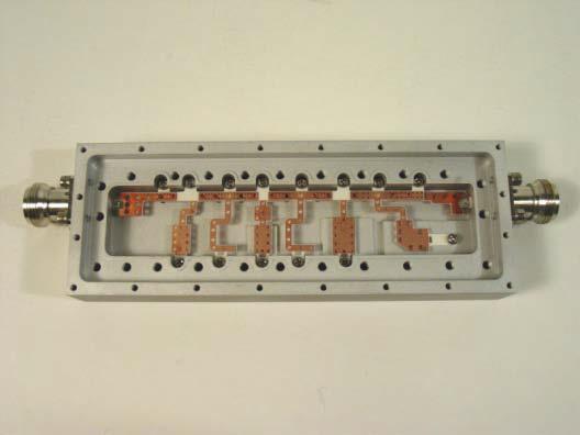
6 BP/BS Duplexer A complete list of available Band- Pass/Band-Stop duplexers is available at the following link: tach/1/_plk287_1_lowpimhp.pdf If your specific need is not covered here, contact K&L for a custom design. 6

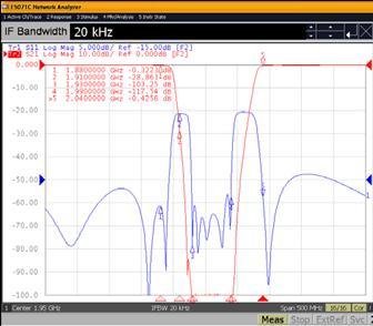
7 BP/BS Typical Data 7


8 BP/BS Typical Data The flatter the PIM response, the fewer the IMD sources. 8


9 High-Pass/Low-Pass Duplexer Applications: Emission Monitoring 2nd and 3rd Harmonic Tests from a Single Tone fo PA fo DUT Spectrum Analyzer 2fo, 3fo. Notes: The LPF passes the fundamental carrier and rejects the Harmonics, preventing them from entering the DUT The HPF terminates Harmonics generated by the PA 9


10 Low PIM High-Pass and Low-Pass Filters 10

 11")

11 Typical Data (Two +43dBm Tones) 11
12 Two Tones-Single Amp-IMD in Band Setup #1a Applications: Two Tones - 3rd IM Reflected and Forward in the Band Tx Tx DUT Non- Reflective SPDT Notes: Signals are combined pre-amplification state. Single amplifier produces two-tones and large IMD levels. Isolator is an IMD source. Spectrum Analyzer Tx filter is required of high rejection levels >-115dBc. Carriers are rejected back into the isolator. filter is required to attenuate the carriers to <-60dBm, to reduce IM products inside the Spectrum Analyzer. Hard to obtain low IMD base line. 12


13 Two Tones-Single Amp-IMD in Band Setup #1b Tx DUT Spectrum Analyzer Notes: Reflected Mode only Difficult to obtain a base line 13
14 Two Tones-Two Amps-IMD in Band Setup #2a TX1 Tx Tx DUT TX2 Non- Reflective SPDT Notes: Most popular; cheap, easy to assemble Amplifiers seem to be isolated by roughly 50dB Spectrum Analyzer Reflected TX1 and TX2 signals are travelling back to isolators, by nature ferromagnetic devices Secondary IM products are generated, due to reflections, which tends to raise the base line of the setup Tx filter must present at least 100dB rejection to the band, preventing IM products from the iso-coupler from travelling to the Spectrum Analyzer filter needs to present 100dB to Tx band, reducing +43dBm tones from mixing inside the Spectrum Analyzer Amplifiers need to present extra 3.5dB gain to compensate for the 3dB hybrid and isolators 14
15 Two Tones-Two Amps-IMD in Band Setup #2b TX1 Tx DUT TX2 Spectrum Analyzer Notes: Reflected Mode only 15
16 IMD Test Setup #3 Applications: Inter-Cell Interference in Forward mode Tx1 Tx1 Tx Tx2 Tx2 DUT Spectrum Analyzer Notes: Two narrow band filters substituted for the -3dB Hybrid The output duplexer covers the entire down-link and up-link bands Input duplexer must be of high quality (always), since it s difficult to pinpoint IMD sources 16

17 Duplexers (BP/BP) 100dB Tx- & 161dBc PIM (Two +43dBm Tones) A complete list of available Low PIM Band-Pass/Band-Pass Duplexers is available at the following link: attach/2/_plk315_1_daslowpimds.pdf If your specific need is not covered here, contact K&L for a custom design. 17
18 Two Signals-BP/BP/BP (Triplexer)-IMD Test Setup #4a Tx1 Tx1 Tx1 Tx2 Tx2 DUT Tx2 Non- Reflective SPDT Notes: IM test in Reverse and Forward mode Base line is easy to maintain All ports are tuned for -20dB return loss Easy to maintain and debug problems Spectrum Analyzer 18

19 Two Signals-BP/BP/BP (Triplexer)-IMD Test Setup #4b Tx1 Tx2 Spectrum Analyzer Tx1 Tx2 DUT A complete list of available Low PIM Triplexers is available at the following link: 3GPPTriplexers.pdf If your specific need is not covered here, contact K&L for a custom design. Notes: Amplifiers are isolated by 75dB filter presents 100dB in Tx band Tx1 and Tx2 are relatively narrow (about 1/3 of down-link bandwidth), reducing the out-of-band noise of the amplifiers Tx2 can be dedicated to a Blocker signal Triplexer can be self-tested - easy to maintain 19
20 Two Signals-Both Ports of DUT-IMD Test Setup #5 Tx1 Tx1 Tx1 Tx2 DUT Tx2 Tx2 Non- Reflective SPDT Spectrum Analyzer Notes: DUT is subjected to two signals, one from each port Filtering the signals provides flow and avoids reflections, reducing possible IMD sources 20

21 Low PIM Triplexers (BP/BP/BP) f1 f2 1.5dB f3 f4 f5 f6 RX TX1 TX2 75 db 100 db Triplexers can be self- tested Easy to maintain the base line Tx1 Tx2 Tx1 Tx2 Spectrum Analyzer 21
 Tx BRF Tx+ Electrical Scheme Frequency Response Notes: Tx,, and BRF are isolated by 75dB All three filters are tuned")
22 The Blockers are Everywhere! BRF/BPF/BPF (Quadraplexer) Tx BRF Tx+ Electrical Scheme Frequency Response Notes: Tx,, and BRF are isolated by 75dB All three filters are tuned for 20dB return loss to reduce uncertainty of measurement BRF provides 20dB of match over all specified Blockers 22


23 Extending the Passband of the Triplexer- Reverse IMD Tx Tx Spectrum Analyzer DUT BRF Tx+ Blockers Non- Reflective SPDT The Quadraplexer: Blocker Signal Gen. Enables all combinations of Blockers and Tx signals 23
 Blockers: 80MHz, 1800MHz, 3800MHz, and")
24 LTE Band 2: Actual Data Tx: MHz (1880MHz) : MHz (1960MHz) Blockers: 80MHz, 1800MHz, 3800MHz, and 5800MHz 24
")
25 LTE Band 2: Actual Data (continued) 25

26 Tx + Blocker IMD Test Data Tx1 1855MHz Tx2 1775MHz 3 rd IMD 1935MHz Enables mixing the Tx signal with many Blockers through the BRF Limited only by the BRF upper-passband match Easy to maintain 26
")
27 LTE Band 2: Actual Data (continued) 27


28 LTE Band 2: Tx signal and Blockers 28


29 Tx + Blocker -IMD Test Setup #6a Tx Tx Tx BRF Tx+ DUT BRF Tx+ Blocker Signal Gen. Non- Reflective SPDT Spectrum Analyzer Notes: Reverse and Forward IMD measurements Easy to maintain and debug 29
30 Tx + Blocker Port Swapping-IMD Test Setup #6b Spectrum Analyzer SP2T Non- Reflective Tx SP2T Non- Reflective Tx Tx DUT BRF Tx+ Blockers Blockers BRF Tx+ Non- Reflective SP4T Blocker Signal Gen. Enables exposing the DUT to one Tx signal and any Blockers with port swapping capability Enables measurements for Reverse and Forward 30

31 Mix-n-Match (LTE Band 7) Triplexer/Duplexer BPF BPF BPF DUT BPF BPF Spectrum Analyzer 31
 band, from a different system. http://www.ni.")
32 Triple Beat & 3rd IMD for RF Switches Triple Beat and IMD for RF Switches emulates two Transmit carriers of the mobile up-link, separated by 1MHz, entering the DUT, along with a Jammer ( Blocker ), representing a weaker signal in the mobile down-link (Receive) band, from a different system. IM 3 rd are f3-(f2-f1) and f3- (f2+f1) Concerns with the proposed block diagram : The two Tx carriers mix with the Jammer in the CW source Limited isolation between the amplifiers - return loss limit. Jammer signal travels directly into the Spectrum Analyzer 32

33 Triple Beat Filter Based - Phase 1 TX1 Tx Tx DUT TX2 Spectrum Analyzer Blocker Source Notes: Jammer CW source is now protected from the two TX signals One problem remains: Energy of TX1 and TX2 is reflected back from Tx Filter and DUT, F1 goes to AMP1 and AMP2 and vice versa Further mixing is taking place at the isolators 33

34 Triple Beat Filter Based - Phase 2 f1 f1 f1+f2 f2 f2 DUT Spectrum Analyzer IM f3 f3 IM in Band = f3-(f2-f1) & f3+(f2-f1) Notes: Hi Q ceramic puck filter can provide ~40dB rejection Adding isolators can increase the isolation to ~60dB Carriers are terminated after passing through the DUT Depending on Jammer power level, this setup should be able to provide a good base line 34
35 Triple Beat Filter Based - Phase 3 Introducing the narrow band BP/BS Duplexer 2MHz The Band-Pass filter is passed f3 and rejects the IMD products by 40dB. The Band-Stop filter passes the IMD products and rejects f3 by 40dB. The Band-Pass filter (or Band-Stop filter) can be terminated, providing a broadband match to common port. 35
36 Triple Beat Filter Based - Phase 4 f1 f1 f1+f2 f2 f2 DUT IM f3 f3 Spectrum Analyzer Notes: Units enclosed in dashed line are all integrated Number of external connections and jumpers kept to a minimum 36

 Can be used to measure IM products and NF and for Triple")
37 The Road Map to Test Rack System ATE Integrations Supports automated production testing of wireless systems and semiconductor product families covering all LTE bands Provides emission monitoring while maintaining a good impedance match with the device under test (DUT) Can be used to measure IM products and NF and for Triple Beat tests 37


, HTTP Server, LabVIEW-based")
")
38 Switch Matrix Next Generation Matrix Modular Architecture flexibility reconfigurable expandable Compact Structure reduce 10X10 rack space from 4U to 3U Trouble-free Maintenance field serviceable field upgradable Removable Power Supply easy access redundant power supplies available Fast Switching Time < 50ms Interface Options Ethernet (TCP/IP), HTTP Server, LabVIEW-based Web Services, RS-232, USB, GPIB,... Power Module (Mounts Vertically for 3U and 4U Enclosures) Mounting Brackets for Switches 2U Model 38


39 Custom Solutions Low PIM Test Station for. Cell Phone Tester for.. 39

40 Coaxial Switch - Data 40


 41")
41 The Road Map to Test Rack System (cont.) 41
42 Interface Options Most switchable RF devices provide a combination of remote and local interfaces. A typical unit is equipped with one or two of the following options: o SNMP SNMP v.1 SNMP v.3 (coming soon) o LabVIEW-based Web Services o GPIB o Ethernet (Built-in Web Server) o USB o RS-232 o CAN-bus -- load the Lua VISA wrapper require "visa" -- open connection to equipment if interface == "GPIB" then -- use GPIB interface 0 at address 16 c = visa.open "GPIB0::16::INSTR" else if interface == "SERIAL" then -- use serial (RS-232, RS-485, etc) interface 1 c = visa.open "ASRL1::INSTR" else if interface == "TCP" then -- use TCP/IP over interface 0 c = visa.open "TCPIP0:: ::7::SOCKET" end -- set switch 1 to position 2 c:write "CT1.2" 42
43
P I M. Low PIM, High-Power Filter Solutions for Monitoring Broadband Emissions. Features: Broadband PIM Monitoring. General Concept for Low PIM ATE
 Features: Patent pending solution enables monitoring of PIM (Passive IM) up to 13 GHz, with high-power capabilities Near end monitoring: carriers are rejected -90 db by the notch filter and travel through
Low Loss Combiner LLC-1900-IN DATA SHEET. Overview
 DATA SHEET Combines Multiple Technologies onto a Single Feed Line Low Loss Combining Combining for Multiple Technologies (GSM/UMTS, UMTS/UMTS, UMTS/LTE, CDMA/LTE, etc.) Minimal or No Guard Band High Reliability
Demo Circuit DC550A Quick Start Guide.
 May 12, 2004 Demo Circuit DC550A. Introduction Demo circuit DC550A demonstrates operation of the LT5514 IC, a DC-850MHz bandwidth open loop transconductance amplifier with high impedance open collector
Major Products. RF/Microwave provider
 Major Products Products 1 RF Sub-systems Combiner FEU TTA TMA SCU 2 Products 2 RF components Power Splitter (BTS) Filter Switch Coupler 3 Feature1 Divider Frequency Range 824~894, 1750~1870, 1885~2170,
Multi-function Site Passive Intermodulation Analyzer.
 Multi-function Site Passive Intermodulation Analyzer www.rosenbergerap.com 01 Introduction Rosenberger HQ, Bavaria, Germany 01 A Rosenberger Hochfrequenztechnik GmbH&Co. was founded in Germany in 1958
Cellular (850 Band) DAS. Tray with Independent Control. General Information. Key Features: Tel: Fax:
 DAS. Tray with Independent Control. General Information. Key Features: Tel: Fax:") Cellular (850 Band) DAS Interface Tray with Independent Control Tel: 201-342-3338 www.cciproducts.com General Information CCI s Cellular Band DAS Interface Tray with Independent Control provides an integrated,
Cellular (850 Band) DAS Interface Tray with Independent Control Tel: 201-342-3338 www.cciproducts.com General Information CCI s Cellular Band DAS Interface Tray with Independent Control provides an integrated,
Spectrum Sharing 900 MHz Combiner
 DATA SHEET Combines two 900 MHz base station outputs with a narrow guard band onto a common port Full transmit and receive band combining with a guard band of 0.8 to 3 MHz High power 400 W per input port
RADIO RECEIVERS ECE 3103 WIRELESS COMMUNICATION SYSTEMS
 RADIO RECEIVERS ECE 3103 WIRELESS COMMUNICATION SYSTEMS FUNCTIONS OF A RADIO RECEIVER The main functions of a radio receiver are: 1. To intercept the RF signal by using the receiver antenna 2. Select the
ANTENNAFIER TM 915LTX BLOCK DIAGRAM LNA
 Digitally Tunable 0.5 to 10 Watts This 915 LTX is a Outdoor High Power Digitally Tunable Bi-Directional Amplifier for 802.11b/g WLAN. It s tuned and powered over a 50 Ohm coax. Now you can fine tune your
RF Components Product Catalogue
 RF Components Product Catalogue Government and Defence Broadcast Marine, Oil and Gas SNG and VSAT RF Engineering by Design Contents Splitters / Combiners Active Splitters and Combiners Page 3 Passive Splitters
Keysight Technologies Innovative Passive Intermodulation (PIM) and S-parameter Measurement Solution with the ENA. Application Note
 and S-parameter Measurement Solution with the ENA. Application Note") Keysight Technologies Innovative Passive Intermodulation () and S-parameter Measurement Solution with the ENA Application Note Introduction Passive intermodulation () is a form of intermodulation distortion
Keysight Technologies Innovative Passive Intermodulation () and S-parameter Measurement Solution with the ENA Application Note Introduction Passive intermodulation () is a form of intermodulation distortion
Multi-Function Assemblies
 K&L Microwave offers a variety of (MFA) products to satisfy a broad range of filtering applications. Many applications require frequency pre-selection at the front end of the communication or test and
5G and mmwave Testing
 5G and mmwave Testing 5G and mmwave Testing The development and deployment of 5G technology is changing the way wireless carriers and internet service providers think about meeting the ever increasing
Session 3. CMOS RF IC Design Principles
 Session 3 CMOS RF IC Design Principles Session Delivered by: D. Varun 1 Session Topics Standards RF wireless communications Multi standard RF transceivers RF front end architectures Frequency down conversion
70/140 MHz IF Fiber Optic Link
 70/140 MHz IF Fiber Optic Link Product Description Features & Benefits IF-Band: 10 200 MHz Up to 10Km distance Powerful management capabilities via a front panel LCD and rack mounted SNMP 1550nm and CWDM
Portable Passive Intermodulation Test Set
 Data Sheet Pim 20 Portable Passive Intermodulation Test Set Taking performance to a new peak Pim 20 - Portable Passive Intermodulation Test Set The Pim 20 is a microprocessor controlled, portable test
TSEK38 Radio Frequency Transceiver Design: Project work B
 TSEK38 Project Work: Task specification A 1(15) TSEK38 Radio Frequency Transceiver Design: Project work B Course home page: Course responsible: http://www.isy.liu.se/en/edu/kurs/tsek38/ Ted Johansson (ted.johansson@liu.se)
Intermodulation Distortion in RF Connectors
 Intermodulation Distortion in RF Connectors Introduction Intermodulation distortion or IMD has always existed in RF transmission paths. Until about the early 1990 s, cellular communications had relatively
TRANSMITTER COMBINERS
 1 TRANSMITTER COMBINERS 30-88 MHz LOWBAND COMBINERS Telewave Lowband and Midband Combiners offer high performance with industry-standard Telewave reliability. Telewave is one of the few remaining manufacturers
PXI Modules 3066 PXI Multi-Way Active RF Combiner Data Sheet
 PXI Modules 3066 PXI Multi-Way Active RF Combiner Data Sheet The most important thing we build is trust 250 MHz to 6 GHz RF signal conditioning module for multi- UE, MIMO and Smartphone testing Four full
For detailed specifications or for your custom application, please contact your K&L sales representative. 20 db High Power Attenuator
 DAS Overview As the LTE rollout continues and cellular frequency bands grow more congested, continuity of coverage becomes more challenging. Distributed Antenna Systems (DAS) provide one way to increase
3H Communication. Systems. RF Filters & Front-End Systems Experts
 Relentless Innovations Amplitude 5f1-4f2 4f1-3f2 3f1-2f2 2f1-f2 f1 f2 2f2-f1 3f2-2f1 4f2-3f1 5f2-4f1 Frequency 0 0-10 -20-10 -30-40 -20-50 -60-30 -70-80 -40-90 -100-50 1685 1710 1735 1760 1785 1810 1835
MINIMIZING SITE INTERFERENCE
 MINIMIZING SITE INTERFERENCE CHAPTER 8 This chapter provides information on preventing radio frequency (RF) interference at a communications site. The following topics are included: Interference Protection
Analog Devices Welcomes Hittite Microwave Corporation NO CONTENT ON THE ATTACHED DOCUMENT HAS CHANGED
 Analog Devices Welcomes Hittite Microwave Corporation NO CONTENT ON THE ATTACHED DOCUMENT HAS CHANGED www.analog.com www.hittite.com THIS PAGE INTENTIONALLY LEFT BLANK 17 Product Application Notes Introduction
Mission Critical DAS Solution
 Mission Critical DAS Solution In-Building Cellular Satellite Phone Coverage Mission Critical DAS solution for In-Building Systems provides a simple, low-cost, limitless bandwidth method to distribute multi-channel,
Custom Rack Mount Test Equipment Guide. Mini-Circuits. NEW!
 NEW! Modular Test Solutions Delivered within 2 Weeks! See Page 44 for Details CRM/TEG-14 Custom Rack Mount Test Equipment Guide ISO 9001 ISO 14001 AS 9100 CERTIFIED www.minicircuits.com CRM_TEG_v3.indd
DAS Interface Module DAST-700-MODA-30 DATA SHEET. Overview
 DATA SHEET A common connection point for Upper and Lower Band LTE Base stations to a single DAS system Levels and equalizes performance for all base stations with Integrated Level Controls No need to attenuate
Advanced Test Equipment Rentals ATEC (2832)
") Established 1981 Advanced Test Equipment Rentals www.atecorp.com 800-404-ATEC (2832) Data Sheet Pim 31 Passive Intermodulation Analyzer 2 x 20W Taking performance to a new peak PIM 31 - Passive Intermodulation
Established 1981 Advanced Test Equipment Rentals www.atecorp.com 800-404-ATEC (2832) Data Sheet Pim 31 Passive Intermodulation Analyzer 2 x 20W Taking performance to a new peak PIM 31 - Passive Intermodulation
3H Communication. Filters, Multiplexers, Switch Filter Banks and RF Front-End Assemblies. Relentless Innovations. Systems
 Relentless Innovations Filters, Multiplexers, Switch Filter Banks and RF Front-End Assemblies Vision We understand that highest quality is achieved when quality is designed in and this often will lead
PXI LTE/LTE-A Downlink (FDD and TDD) Measurement Suite Data Sheet
 Measurement Suite Data Sheet") PXI LTE/LTE-A Downlink (FDD and TDD) Measurement Suite Data Sheet The most important thing we build is trust Designed for the production test of the base station RF, tailored for the evolving small cell
PXI LTE/LTE-A Downlink (FDD and TDD) Measurement Suite Data Sheet The most important thing we build is trust Designed for the production test of the base station RF, tailored for the evolving small cell
Solid State Broadband High Power Amplifier
 The BBS4A5AVT (2157) is suitable L & S Bands broadband or band specific high power applications. This amplifier utilizes high power GaN devices that provide wide frequency response, high gain, high peak
Venue 2 TECHNICAL DATA. Six Channel Modular Receiver. Digital Hybrid Wireless. Featuring Digital Hybrid Wireless Technology
 Venue 2 Six Channel Modular Receiver Featuring Digital Hybrid Wireless Technology TECHNICAL DATA 3-block tuning for up to 76 MHz and 3072 synthesized UHF frequencies per receiver module Six-channel modular
Combined Band MHz. Fig. 1 Typical Diplexer Filter Combiner Fig. 2 Typical Diplexer Combiner
 Choosing the Best Power Divider for the Task of Signal Combining As systems become more and more complex, choosing how best to combine two or more RF signals has become a far more difficult question to
CHAPTER - 6 PIN DIODE CONTROL CIRCUITS FOR WIRELESS COMMUNICATIONS SYSTEMS
 CHAPTER - 6 PIN DIODE CONTROL CIRCUITS FOR WIRELESS COMMUNICATIONS SYSTEMS 2 NOTES 3 INTRODUCTION PIN DIODE CONTROL CIRCUITS FOR WIRELESS COMMUNICATIONS SYSTEMS Chapter 6 discusses PIN Control Circuits
TDK RF Products Training Module for Mouser
 TDK RF Products Training Module for Mouser Jan, 2011 TDK RF Overview Introduction to TDK RF Components and their applications RF Product Marketing A ttenuation A ttenuation A ttenuation What is a BPF/LPF/Diplexer/Coupler/?
Analog Devices Welcomes Hittite Microwave Corporation NO CONTENT ON THE ATTACHED DOCUMENT HAS CHANGED
 Analog Devices Welcomes Hittite Microwave Corporation NO CONTENT ON THE ATTACHED DOCUMENT HAS CHANGED www.analog.com www.hittite.com THIS PAGE INTENTIONALLY LEFT BLANK v01.05.00 HMC141/142 MIXER OPERATION
HF Transmit/Receive Broadband System XB 2900
 Data sheet HF Transmit/Receive Broadband System XB 2900 Especially designed for naval operational environment Full HF frequency band (2 MHz to 30 MHz) for voice, data, and ALE operation Flexible system
Configuration of PNA-X, NVNA and X parameters
 Configuration of PNA-X, NVNA and X parameters VNA 1. S-Parameter Measurements 2. Harmonic Measurements NVNA 3. X-Parameter Measurements Introducing the PNA-X 50 GHz 43.5 GHz 26.5 GHz 13.5 GHz PNA-X Agilent
Introduction to Surface Acoustic Wave (SAW) Devices
 Devices") May 31, 2018 Introduction to Surface Acoustic Wave (SAW) Devices Part 7: Basics of RF Circuits Ken-ya Hashimoto Chiba University k.hashimoto@ieee.org http://www.te.chiba-u.jp/~ken Contents Noise Figure
May 31, 2018 Introduction to Surface Acoustic Wave (SAW) Devices Part 7: Basics of RF Circuits Ken-ya Hashimoto Chiba University k.hashimoto@ieee.org http://www.te.chiba-u.jp/~ken Contents Noise Figure
Intermodulation Distortion in RF Connectors
 a division of RF Industries Intermodulation Distortion in RF Connectors Introduction Intermodulation distortion or IMD has always existed in RF transmission paths. Until about the early 1990 s, cellular
High Dynamic Range Receiver Parameters
 High Dynamic Range Receiver Parameters The concept of a high-dynamic-range receiver implies more than an ability to detect, with low distortion, desired signals differing, in amplitude by as much as 90
4 channel low power Active DAS tray with power monitoring and attenuation control (+18dBm maximum average
 Active DCC Brochure DCC500 Series Products DAS Control Rack (DCR) A broadband active multi-channel device with programmable uplink/downlink variable attenuators and RMS power monitors for remote or local
Receiver Design. Prof. Tzong-Lin Wu EMC Laboratory Department of Electrical Engineering National Taiwan University 2011/2/21
 Receiver Design Prof. Tzong-Lin Wu EMC Laboratory Department of Electrical Engineering National Taiwan University 2011/2/21 MW & RF Design / Prof. T. -L. Wu 1 The receiver mush be very sensitive to -110dBm
Understanding Mixers Terms Defined, and Measuring Performance
 Understanding Mixers Terms Defined, and Measuring Performance Mixer Terms Defined Statistical Processing Applied to Mixers Today's stringent demands for precise electronic systems place a heavy burden
Using measurement methods described in Australian/New Zealand Standard AS/NZS 4770:2000
 Barrett 2050 HF transceiver Using measurement methods described in Australian/New Zealand Standard AS/NZS 4770:2000 General Specifications Equipment Standards Transmit frequency range Receive frequency
BGU8309 GNSS LNA evaluation board
 BGU8309 GNSS LNA evaluation board Rev. 2 12 August 2016 Application note Document information Info Content Keywords BGU8309, GNSS, LNA Abstract This document explains the BGU8309 GNSS LNA evaluation board
GaAs Junction gate phemt (JPHEMT) MMIC switch, CMOS decoder
 MMIC switch, CMOS decoder") SP4T + SP6T Antenna Switch Module for 6TRx/2Tx/2Rx with SPI I/F CXM3580AUR Description The CXM3580AUR is a SP4T+ SP6T antenna switch module for GSM/UMTS/CDMA /LTE multi-mode handset. The CXM3580AUR has
SP4T + SP6T Antenna Switch Module for 6TRx/2Tx/2Rx with SPI I/F CXM3580AUR Description The CXM3580AUR is a SP4T+ SP6T antenna switch module for GSM/UMTS/CDMA /LTE multi-mode handset. The CXM3580AUR has
INTRODUCTION TO TRANSCEIVER DESIGN ECE3103 ADVANCED TELECOMMUNICATION SYSTEMS
 INTRODUCTION TO TRANSCEIVER DESIGN ECE3103 ADVANCED TELECOMMUNICATION SYSTEMS FUNCTIONS OF A TRANSMITTER The basic functions of a transmitter are: a) up-conversion: move signal to desired RF carrier frequency.
Understanding RF and Microwave Analysis Basics
 Understanding RF and Microwave Analysis Basics Kimberly Cassacia Product Line Brand Manager Keysight Technologies Agenda µw Analysis Basics Page 2 RF Signal Analyzer Overview & Basic Settings Overview
UM User manual for the BGU7004 GPS LNA evaluation board. Document information. Keywords LNA, GPS, BGU7004. Abstract
 User manual for the BGU7004 GPS LNA evaluation board Rev. 1.0 14 June 2011 User manual Document information Info Keywords Abstract Content LNA, GPS, BGU7004 This document explains the BGU7004 AEC-Q100
Page : 1 / 221 TEST REPORT. Corning Optical Communications Wireless Inc.
 Page : 1 / 221 TEST REPORT Report number Name RAPA15-O-035 Corning Optical Communications Wireless Inc. Applicant Logo Manufacturer Address Name Address 13221 Woodland Park Rd, Suite 400 Herndon, Virginia
SC5307A/SC5308A 100 khz to 6 GHz RF Downconverter. Datasheet SignalCore, Inc.
 SC5307A/SC5308A 100 khz to 6 GHz RF Downconverter Datasheet 2017 SignalCore, Inc. support@signalcore.com P RODUCT S PECIFICATIONS Definition of Terms The following terms are used throughout this datasheet
QUICK START GUIDE FOR DEMONSTRATION CIRCUIT 678A 40MHZ TO 900MHZ DIRECT CONVERSION QUADRATURE DEMODULATOR
 DESCRIPTION QUICK START GUIDE FOR DEMONSTRATION CIRCUIT 678A LT5517 Demonstration circuit 678A is a 40MHz to 900MHz Direct Conversion Quadrature Demodulator featuring the LT5517. The LT 5517 is a direct
IMD Measurement Wizard for the E5072A ENA Series Network Analyzer Operation Manual. Agilent Technologies June 2012
 IMD Measurement Wizard for the E5072A ENA Series Network Analyzer Operation Manual Agilent Technologies June 2012 1 Important Notice Notices The information contained in this document is subject to change
MCP to 2.5 GHz RF Front End IC. Description
 Description The contains a power amplifier (PA), a low noise amplifier (LNA), and two SPDT switch. It is a 0-pins IC by 4 4mm -QFN package. RF input and output impedance of are 50Ω matched. Therefore,
SPECIAL SPECIFICATION 6744 Spread Spectrum Radio
 2004 Specifications CSJ 0924-06-244 SPECIAL SPECIFICATION 6744 Spread Spectrum Radio 1. Description. Furnish and install spread spectrum radio system. 2. Materials. Supply complete manufacturer specifications
Improved Measurement of Passive Intermodulation Products
 Presentation to: ANAMET Improved Measurement of Passive Intermodulation Products James Miall Date: March 2004 Introduction PIM = Passive InterModulation IMD = InterModulation Distortion PIM is mixing of
Satellite Communications Testing
 Satellite Communications Testing SATELLITE COMMUNICATIONS TESTING Traditionally, the satellite industry has relied on geosynchronous earth orbit (GEO) satellites that take years to build and require very
Electro-Optical Performance Requirements for Direct Transmission of 5G RF over Fiber
 Electro-Optical Performance Requirements for Direct Transmission of 5G RF over Fiber Revised 10/25/2017 Presented by APIC Corporation 5800 Uplander Way Culver City, CA 90230 www.apichip.com 1 sales@apichip.com
ID-5100 User Evaluation & Test Report
 ID-5100 User Evaluation & Test Report By Adam Farson VA7OJ/AB4OJ Iss. 1, August 13, 2014. Part I: Brief User Evaluation. Introduction: This report describes the evaluation and lab test of ID-5100 S/N 05001175.
SC5407A/SC5408A 100 khz to 6 GHz RF Upconverter. Datasheet. Rev SignalCore, Inc.
 SC5407A/SC5408A 100 khz to 6 GHz RF Upconverter Datasheet Rev 1.2 2017 SignalCore, Inc. support@signalcore.com P R O D U C T S P E C I F I C A T I O N S Definition of Terms The following terms are used
RF and Microwave Design Solutions. Bob Alman (707)
") RF and Microwave Design Solutions Bob Alman (707) 529-8481 Bob@AlmanEngineering.com Santa Rosa, CA About Bob Alman Bob Alman acts as an extension of your engineering team by providing guidance, application
RF and Microwave Design Solutions Bob Alman (707) 529-8481 Bob@AlmanEngineering.com Santa Rosa, CA About Bob Alman Bob Alman acts as an extension of your engineering team by providing guidance, application
RF Subsytems & Components.
 RF Subsytems & Components wwwtroncomtr Page 2/13 Tron Elektronik AS benefits from the experience gained for more than 20 years in design and production of Broadband CATV network products Tron Elektronik
AN BGU8309 GNSS LNA + B13 notch filter evaluation board. Document information. Keywords. BGU8309, GNSS, LNA Abstract
 BGU8309 GNSS LNA + B13 notch filter evaluation board Rev. 1 30 November 2016 Application note Document information Info Content Keywords BGU8309, GNSS, LNA Abstract This document explains the BGU8309 GNSS
TSEK38: Radio Frequency Transceiver Design Lecture 7: Receiver Synthesis (II)
") TSEK38: Radio Frequency Transceiver Design Lecture 7: Receiver Synthesis (II) Ted Johansson, ISY ted.johansson@liu.se Systematic Receiver Synthesis (II) 4.3 Intermodulation characteristics Phase noise
TSEK38: Radio Frequency Transceiver Design Lecture 7: Receiver Synthesis (II) Ted Johansson, ISY ted.johansson@liu.se Systematic Receiver Synthesis (II) 4.3 Intermodulation characteristics Phase noise
SDR-BASED TEST BENCH TO EVALUATE ANALOG CANCELLATION TECHNIQUES FOR IN-BAND FULL-DUPLEX TRANSCEIVER
 SDR-BASED TEST BENCH TO EVALUATE ANALOG CANCELLATION TECHNIQUES FOR IN-BAND FULL-DUPLEX TRANSCEIVER Patrick Rosson, David Dassonville, Xavier Popon, Sylvie Mayrargue CEA-Leti Minatec Campus Cleen Workshop,
PIM Master Anritsu Field Testing PIM Solution
 PIM Master Anritsu Field Testing PIM Solution Featuring Distance-to-PIM (DTP) The Fastest Way to Pinpoint the Source of PIM Slide 1 Learning about PIM and PIM testing What is PIM? Why do we care about
TMR6200 HF Naval Digital Transceivers
 TMR6200 HF Naval Digital Transceivers One or Two High Performance 500 W/1 kw Transceivers in a Single Cabinet 125 W High Performance Transceiver In a 4U/19-inch Chassis Outstanding RF Performance Optimized
HF Power Amplifier (Reference Design Guide) RFID Systems / ASP
 RFID Systems / ASP") 16 September 2008 Rev A HF Power Amplifier (Reference Design Guide) RFID Systems / ASP 1.) Scope Shown herein is a HF power amplifier design with performance plots. As every application is different and
16 September 2008 Rev A HF Power Amplifier (Reference Design Guide) RFID Systems / ASP 1.) Scope Shown herein is a HF power amplifier design with performance plots. As every application is different and
GainMaker Unbalanced Triple System Amplifier 870 MHz with 40/52 MHz Split
 RF Electronics GainMaker Unbalanced Triple System Amplifier 870 MHz with 40/52 MHz Split Description The GainMaker Broadband Amplifier Platform includes a variety of RF amplifiers that address the divergent
TSEK38: Radio Frequency Transceiver Design Lecture 3: Superheterodyne TRX design
 TSEK38: Radio Frequency Transceiver Design Lecture 3: Superheterodyne TRX design Ted Johansson, ISY ted.johansson@liu.se 2 Outline of lecture 3 Introduction RF TRX architectures (3) Superheterodyne architecture
Affordable Design Techniques for Broadband DAS Expansion. Rand Skopas Dir. of Field Sales
 Affordable Design Techniques for Broadband DAS Expansion Rand Skopas Dir. of Field Sales Agenda Challenges of frequency expansion in DAS systems Directional couplers and signal tappers DAS applications
Specifications and Interfaces
 Specifications and Interfaces Crimson TNG is a wide band, high gain, direct conversion quadrature transceiver and signal processing platform. Using analogue and digital conversion, it is capable of processing
Windfreak Technologies SynthHD v1.4 Preliminary Data Sheet v0.2b
 Windfreak Technologies SynthHD v1.4 Preliminary Data Sheet v0.2b $1299.00US 54 MHz 13.6 GHz Dual Channel RF Signal Generator Features Open source Labveiw GUI software control via USB Run hardware functions
SPECIFICATION FREQUENCY RANGE: IBS-6
 IBS Series SYNTHESIZER SPECIFICATION FREQUENCY RANGE: IBS-6 0.1 to 6 GHz IBS-18 2 to 18 GHz IBS-20 0.1 to 20 GHz FEATURES Wide Frequency Bandwidth: 0.1 to 20 GHz Fast Switching Speed: 200 usec, Full Band
The Icom IC Adam Farson VA7OJ. A New Top-class HF/6m Transceiver. IC-7700 Information & Links
 The Icom IC-7700 A New Top-class HF/6m Transceiver Adam Farson VA7OJ IC-7700 Information & Links Copyright 2008 North Shore Amateur Radio Club NSARC HF Operators IC-7700 1 IC-7700 front panel This is a
Radio Receiver Architectures and Analysis
 Radio Receiver Architectures and Analysis Robert Wilson December 6, 01 Abstract This article discusses some common receiver architectures and analyzes some of the impairments that apply to each. 1 Contents
Swept Return Loss & VSWR Antenna Measurements using the Eagle Technologies RF Bridge
 Swept Return Loss & VSWR Antenna Measurements using the Eagle Technologies RF Bridge April, 2015 Page 1 of 7 Introduction Return loss and VSWR are a measure of the magnitude of a transmitted RF Signal
INSTALLATION and OPERATION INSTRUCTIONS. FOR FiberLink BI-DIRECTIONAL AMPLIFIER WITH DIVERSITY MW-FBDA-800AB-50W-DIV
 INSTALLATION and OPERATION INSTRUCTIONS FOR FiberLink BI-DIRECTIONAL AMPLIFIER WITH DIVERSITY MW-FBDA-800AB-50W-DIV Page 1 of 15 TABLE OF CONTENTS PARA No. PARAGRAPH PAGE No. 1. OVERVIEW 3 2. COMPONENT
Optiva OTS-2 18 GHz Amplified Microwave Band Fiber Optic Links
 MHz to 18 GHz Amplified Microwave Transport System The Optiva OTS-2 18 GHz Microwave Band transmitter and receiver are ideal to construct transparent fiber optic links in the MHz to 18 GHz frequency range
Advanced Digital Receiver
 Advanced Digital Receiver MI-750 FEATURES Industry leading performance with up to 4 M samples per second 135 db dynamic range and -150 dbm sensitivity Optimized timing for shortest overall test time Wide
Data Sheet SC5317 & SC5318A. 6 GHz to 26.5 GHz RF Downconverter SignalCore, Inc. All Rights Reserved
 Data Sheet SC5317 & SC5318A 6 GHz to 26.5 GHz RF Downconverter www.signalcore.com 2018 SignalCore, Inc. All Rights Reserved Definition of Terms 1 Table of Contents 1. Definition of Terms... 2 2. Description...
Receiver Architecture
 Receiver Architecture Receiver basics Channel selection why not at RF? BPF first or LNA first? Direct digitization of RF signal Receiver architectures Sub-sampling receiver noise problem Heterodyne receiver
PASSIVE COMPONENTS PASSIVE COMPONENTS.
 PASSIVE COMPONENTS PASSIVE COMPONENTS www.rosenbergerap.com Rosenberger HQ, Bavaria, Germany INTRODUCTION Rosenberger Hochfrequenztechnik GmbH&Co. was founded in Germany in 1958 and ranks among the leading
Application Note: Swept Return Loss & VSWR Antenna Measurements using the Eagle Technologies RF Bridge
 : Swept Return Loss & VSWR Antenna Measurements using the Eagle Technologies RF Bridge FCT-1008A Introduction Return loss and VSWR are a measure of the magnitude of a transmitted RF Signal in relation
PMSE LTE Coexistence
 PMSE LTE Coexistence Results of the JRC measurement session of November 13-15, 2013 www.jrc.ec.europa.eu Serving society Stimulating innovation Supporting legislation LTE-PMSE coexistence measurements
Cell Extender Antenna System Design Guide Lines
 Cell Extender Antenna System Design Guide Lines 1. General The design of an Antenna system for a Cell Extender site needs to take into account the following specific factors: a) The systems input and output
Compact Model Fiber Deep Node 862 MHz with 42/54 MHz Split
 Optoelectronics Compact Model 90090 Fiber Deep Node 862 MHz with 42/54 MHz Split Description The Scientific-Atlanta Compact Model 90090 Fiber Deep Node is a small, low-cost, 110V AC powered node that addresses
Connecting First Responders
 Connecting First Responders Connecting First Responders 1st class antenna, filter and combiner solutions Amphenol s comprehensive product range is serving system integrators, installer- and network operators.
OPTICAL NODE TRUNK & DISTRIBUTION
 OPTICAL NODE TRUNK & DISTRIBUTION OPTI 100RX - OPTI 200RX - OPTI 300RX Version 2 Page 1 OPTI INTRODUCTION OPTI is a broadband distribution node designed to be used as a compact, multiport optical node
S.A. Torchinsky, A. van Ardenne, T. van den Brink-Havinga, A.J.J. van Es, A.J. Faulkner (eds.) 4-6 November 2009, Château de Limelette, Belgium
 4-6 November 2009, Château de Limelette, Belgium") WIDEFIELD SCIENCE AND TECHNOLOGY FOR THE SKA SKADS CONFERENCE 29 S.A. Torchinsky, A. van Ardenne, T. van den Brink-Havinga, A.J.J. van Es, A.J. Faulkner (eds.) 4-6 November 29, Château de Limelette, Belgium
WIDEFIELD SCIENCE AND TECHNOLOGY FOR THE SKA SKADS CONFERENCE 29 S.A. Torchinsky, A. van Ardenne, T. van den Brink-Havinga, A.J.J. van Es, A.J. Faulkner (eds.) 4-6 November 29, Château de Limelette, Belgium
RF8889A SP10T ANTENNA SWITCH MODULE
 SP10T ANTENNA SWITCH MOD- ULE RF8889A SP10T ANTENNA SWITCH MODULE Package: QFN, 3.0mmx3.8mmx0.85mm GSM Rx1 RF8889A GSM Rx2 Features Broadband Performance Suitable for all Cellular Modulation Schemes up
RF System Aspects for SDR. A Tutorial. Dr. Ruediger Leschhorn, Rohde & Schwarz 29. November 2011
 RF System Aspects for SDR A Tutorial Dr. Ruediger Leschhorn, Rohde & Schwarz 29. November 2011 Content Radio System Some Basics Link Budget Cosite Examples Desensitization Blocking, Transmitter Noise,
Optiva OTS-2 40 GHz Amplified Microwave Band Fiber Optic Links
 2 GHz to 4 GHz Amplified Microwave Transport System The Optiva OTS-2 4 GHz Microwave Band transmitter and receiver are ideal to construct transparent fiber optic links in the 5 MHz to 4 GHz frequency range
Transforming MIMO Test
 Transforming MIMO Test MIMO channel modeling and emulation test challenges Presented by: Kevin Bertlin PXB Product Engineer Page 1 Outline Wireless Technologies Review Multipath Fading and Antenna Diversity
Upstream Challenges With DOCSIS 3.1
 Upstream Challenges With DOCSIS 3.1 White Paper A Technical Paper prepared for SCTE/ISBE by Jan Ariesen Chief Technology Officer Technetix Inc 2017 SCTE-ISBE and NCTA. All rights reserved. Title Table
CAVITY TUNING. July written by Gary Moore Telewave, Inc. 660 Giguere Court, San Jose, CA Phone:
 CAVITY TUNING July 2017 -written by Gary Moore Telewave, Inc 660 Giguere Court, San Jose, CA 95133 Phone: 408-929-4400 1 P a g e Introduction Resonant coaxial cavities are the building blocks of modern
Discover TDK Solutions
 Discover TDK Solutions RF Components for Wireless Applications TDK RF Components & Services : Band Pass Filters Diplexers Low Pass Filters Couplers High Inductors Circulators/ Isolators Baluns Antennas
Optiva OTS-2 40 GHz Amplified Microwave Band Fiber Optic Links
 5 MHz to 4 GHz Amplified Microwave Transport System The Optiva OTS-2 4 GHz Microwave Band transmitter and receiver are ideal to construct transparent fiber optic links in the 5 MHz to 4 GHz frequency range
Moveable Probe Thick Silver Plated
 Coarse Tuning Rod Fine Tuning Rod Loop Assembly 1/4 Thick Cavity Top 0.12 Thick Cavity Shell Finish: Gold Iridite Stationary Probe 0.055 Wall Silver Plated Moveable Probe 0.031 Thick Silver Plated Bandpass