INTRODUCTION TO TRANSCEIVER DESIGN ECE3103 ADVANCED TELECOMMUNICATION SYSTEMS
|
|
|
- Sheryl Poole
- 5 years ago
- Views:
Transcription
1 INTRODUCTION TO TRANSCEIVER DESIGN ECE3103 ADVANCED TELECOMMUNICATION SYSTEMS
2 FUNCTIONS OF A TRANSMITTER The basic functions of a transmitter are: a) up-conversion: move signal to desired RF carrier frequency. b) power amplification: amplify signal to deliver wanted power to antenna for emission. The main functions of a radio receiver are: a) To intercept the RF signal by using the receiver antenna b) Select the desired RF signal and reject everything else c) Amplify the RF signal d) Detect the signal and demodulate to yield the original baseband signal e) Amplify the baseband signal
3 TYPES OF RADIO TRANSMITTERS Radio transmitters are basically of two types, i.e 1. Mixer-Based Which can be Direct Conversion (Homodyne) or 2-Stage Conversion (Heterodyne) Both architectures can operate with constant and non-constant envelope modulation Well-suited for multi-standard operation 2. PLL-Based Fundamentally limited to constant-envelope modulation schemes Show promise with respect to elimination of discrete components not suitable for multi-standard operation
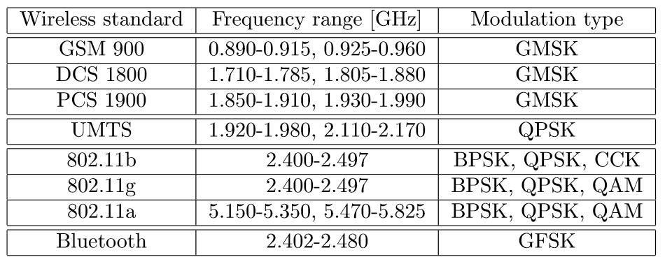
4 MODULATION STANDARDS
5 DIRECT CONVERSION Direct Conversion has the following features 1. It is attractive due to simplicity of the signal path 2. It is suitable for high levels of integration 3. Output carrier frequency is same as local oscillator (LO) frequency 4. Major drawback: LO disturbance by PA output Re(X(t)) Output signal Re(x(t) A c cosω c t + Im(xt)) A c cosω c t Im(X(t)) Note: For frequency and phasemodulated signals, conversion must provide quadrature outputs to avoid loss of information.
6 DRAWBACK OF DIRECT CONVERSION 1. Injection pulling or injection locking results from the noisy output of power amplifier corrupting the output of the VCO. 2. VCO frequency shifts toward frequency of external stimulus due to the feedback. 3. If injected noise frequency is close to oscillator frequency and the noise increases, then the output locks onto noise frequency.
7 SOLUTION TO LOCAL OSCILLATOR (LO) PULLING LO pulling is usually minimized by moving the PA output spectrum sufficiently far from the LO frequency through a process called LO offset. LO offset is achieved by mixing 2 VCO outputs ω 1 and ω 2 and filtering the result; leading to a carrier frequency of ω 1 + ω 2, which is far from either ω1 or ω2. BPF1 must have high selectivity to suppress harmonics from Output signal Re(x(t) A c cos(ω 1 +ω 2 )t + Im(xt)) A c cos(ω 1 + ω 2 )t
8 MHz MHz HOMODYNE RECEIVER
9 TWO-STAGE SUPERHETRODYNE Hetrodyne conversion uses Quadrature modulation at IF (ω 1 )followed by a second up-conversion stage to yield ω 1 + ω 2 by mixing and filtering. Advantages: Has no LO pulling; Has better I/Q matching, i.e less crosstalk between the 2 bit streams. BPF1 suppresses the IF harmonics BPF2 removes the unwanted sideband ω 1 - ω 2
10 2-STAGE SUPERHETRODYNE RECEIVER
11 HETERODYNE RADIO TRANSMITTER WITH SINGLE IF STAGE
12 TRENDS IN TRANSCEIVER INTEGRATION 1. Both Direct conversion and hetrodyne architectures are used with minor modifications for better integration and multi-standard operation. 2. Direct architecture achieves a low-cost solution with a high level of integration stage superhetrodyne architecture results in better performance (i.e. reduced LO pulling) at the expense of increased complexity and hence higher cost of implementation. 4. Transmitter and receiver parts of a transceiver are usually designed concurrently to enable hardware and possibly power sharing
13 EXAMPLE - 5-GHZ CMOS TRANSCEIVER FRONTEND CHIPSET Voltage-Controlled Oscillator on-chip quadrature VCO and buffers to improve frequency purity Duplexer Allows simultaneo us Tx and Rx, Buffers isolate sensitive VCO circuits from high-power, large voltage or current swing circuit blocks
14 A DUAL BAND GSM 900/1800-MHZ CMOS TRANSMITTER Transmitter exploits similarities of GSM 900 and 1800 standards (modulation, channel spacing, antenna duplexing) to reduce hardware f 1 = 450 MHz f 2 = 1350 MHz Two quadrature upconverters driven by 450MHz LO to generate quadrature phases of IF signal. f 1800 = IF signal routed to singlesideband mixers driven by a 1350MHz Local Oscillator, producing either 900MHz or 1800MHz signal f 1 = 450 MHz f 2 = 1350 MHz f 900 =
15 EXAMPLES OF CMOS OSCILLATORS Crystal Crystal (a) Piece Oscillator (b) Miller Oscillator
16 CONVENTIONAL CMOS MIXER LO Signal from Local Oscillator IF Intermediate frequency signal LO Signal from RF Image filter
17 PRINCIPLE OF OPERATION OF CMOS MIXER (a) CMOS Mixer Circuit (b) Current flow in the resistors
18 CHALLENGES IN THE DESIGN OF TRANCEIVER INTEGRATED CIRCUITS 1. Implementation of highly integrated radio transceivers will remain as one of the greatest challenges in IC technology. 2. New architectures and circuit techniques are currently under investigation for higher flexibility in CMOS transmitters. 3. Further improvement are required in the design of on-chip inductors, filters and oscillators in a standard CMOS process. 4. There is need for continued improvement in high frequency CMOS device modelling and simulation.
19 PLL TRANSMITTER
Session 3. CMOS RF IC Design Principles
 Session 3 CMOS RF IC Design Principles Session Delivered by: D. Varun 1 Session Topics Standards RF wireless communications Multi standard RF transceivers RF front end architectures Frequency down conversion
Speed your Radio Frequency (RF) Development with a Building-Block Approach
 Development with a Building-Block Approach") Speed your Radio Frequency (RF) Development with a Building-Block Approach Whitepaper - May 2018 Nigel Wilson, CTO, CML Microcircuits. 2018 CML Microcircuits Page 1 of 13 May 2018 Executive Summary and
Speed your Radio Frequency (RF) Development with a Building-Block Approach Whitepaper - May 2018 Nigel Wilson, CTO, CML Microcircuits. 2018 CML Microcircuits Page 1 of 13 May 2018 Executive Summary and
RF/IF Terminology and Specs
 RF/IF Terminology and Specs Contributors: Brad Brannon John Greichen Leo McHugh Eamon Nash Eberhard Brunner 1 Terminology LNA - Low-Noise Amplifier. A specialized amplifier to boost the very small received
RADIO RECEIVERS ECE 3103 WIRELESS COMMUNICATION SYSTEMS
 RADIO RECEIVERS ECE 3103 WIRELESS COMMUNICATION SYSTEMS FUNCTIONS OF A RADIO RECEIVER The main functions of a radio receiver are: 1. To intercept the RF signal by using the receiver antenna 2. Select the
Demo board DC365A Quick Start Guide.
 August 02, 2001. Demo board DC365A Quick Start Guide. I. Introduction The DC365A demo board is intended to demonstrate the capabilities of the LT5503 RF transmitter IC. This IC incorporates a 1.2 GHz to
Transceiver Architectures (III)
") Image-Reject Receivers Transceiver Architectures (III) Since the image and the signal lie on the two sides of the LO frequency, it is possible to architect the RX so that it can distinguish between the
Image-Reject Receivers Transceiver Architectures (III) Since the image and the signal lie on the two sides of the LO frequency, it is possible to architect the RX so that it can distinguish between the
RFIC Design ELEN 351 Lecture 2: RFIC Architectures
 RFIC Design ELEN 351 Lecture 2: RFIC Architectures Instructor: Dr. Allen Sweet Copy right 2003 ELEN 351 1 RFIC Architectures Modulation Choices Receiver Architectures Transmitter Architectures VCOs, Phase
Superheterodyne Receiver Tutorial
 1 of 6 Superheterodyne Receiver Tutorial J P Silver E-mail: john@rfic.co.uk 1 ABSTRACT This paper discusses the basic design concepts of the Superheterodyne receiver in both single and double conversion
Receiver Architecture
 Receiver Architecture Receiver basics Channel selection why not at RF? BPF first or LNA first? Direct digitization of RF signal Receiver architectures Sub-sampling receiver noise problem Heterodyne receiver
ELEN 701 RF & Microwave Systems Engineering. Lecture 2 September 27, 2006 Dr. Michael Thorburn Santa Clara University
 ELEN 701 RF & Microwave Systems Engineering Lecture 2 September 27, 2006 Dr. Michael Thorburn Santa Clara University Lecture 2 Radio Architecture and Design Considerations, Part I Architecture Superheterodyne
Radio Receiver Architectures and Analysis
 Radio Receiver Architectures and Analysis Robert Wilson December 6, 01 Abstract This article discusses some common receiver architectures and analyzes some of the impairments that apply to each. 1 Contents
QUICK START GUIDE FOR DEMONSTRATION CIRCUIT 678A 40MHZ TO 900MHZ DIRECT CONVERSION QUADRATURE DEMODULATOR
 DESCRIPTION QUICK START GUIDE FOR DEMONSTRATION CIRCUIT 678A LT5517 Demonstration circuit 678A is a 40MHz to 900MHz Direct Conversion Quadrature Demodulator featuring the LT5517. The LT 5517 is a direct
Radioelectronics RF CMOS Transceiver Design
 Radioelectronics RF CMOS Transceiver Design http://www.ek.isy.liu.se/ courses/tsek26/ Jerzy Dąbrowski Division of Electronic Devices Department of Electrical Engineering (ISY) Linköping University e-mail:
ISSCC 2003 / SESSION 20 / WIRELESS LOCAL AREA NETWORKING / PAPER 20.2
 ISSCC 2003 / SESSION 20 / WIRELESS LOCAL AREA NETWORKING / PAPER 20.2 20.2 A Digitally Calibrated 5.15-5.825GHz Transceiver for 802.11a Wireless LANs in 0.18µm CMOS I. Bouras 1, S. Bouras 1, T. Georgantas
Lecture 15: Introduction to Mixers
 EECS 142 Lecture 15: Introduction to Mixers Prof. Ali M. Niknejad University of California, Berkeley Copyright c 2005 by Ali M. Niknejad A. M. Niknejad University of California, Berkeley EECS 142 Lecture
ADI 2006 RF Seminar. Chapter II RF/IF Components and Specifications for Receivers
 ADI 2006 RF Seminar Chapter II RF/IF Components and Specifications for Receivers 1 RF/IF Components and Specifications for Receivers Fixed Gain and Variable Gain Amplifiers IQ Demodulators Analog-to-Digital
Radio Research Directions. Behzad Razavi Communication Circuits Laboratory Electrical Engineering Department University of California, Los Angeles
 Radio Research Directions Behzad Razavi Communication Circuits Laboratory Electrical Engineering Department University of California, Los Angeles Outline Introduction Millimeter-Wave Transceivers - Applications
FEATURES DESCRIPTION BENEFITS APPLICATIONS. Preliminary PT4501 Sub-1 GHz Wideband FSK Transceiver
 Preliminary PT4501 Sub-1 GHz Wideband FSK Transceiver DESCRIPTION The PT4501 is a highly integrated wideband FSK multi-channel half-duplex transceiver operating in sub-1 GHz license-free ISM bands. The
Introduction to Receivers
 Introduction to Receivers Purpose: translate RF signals to baseband Shift frequency Amplify Filter Demodulate Why is this a challenge? Interference Large dynamic range required Many receivers must be capable
RF Integrated Circuits
 Introduction and Motivation RF Integrated Circuits The recent explosion in the radio frequency (RF) and wireless market has caught the semiconductor industry by surprise. The increasing demand for affordable
TSEK38: Radio Frequency Transceiver Design Lecture 3: Superheterodyne TRX design
 TSEK38: Radio Frequency Transceiver Design Lecture 3: Superheterodyne TRX design Ted Johansson, ISY ted.johansson@liu.se 2 Outline of lecture 3 Introduction RF TRX architectures (3) Superheterodyne architecture
Transceiver Architectures
 + Transceiver Architectures Outline Heterodyne Receivers! Problem of Image! Mixing Spurs! Sliding-IF RX Direct-Conversion Receivers! LO Leakage and Offsets! Even-Order Nonlinearity! I/Q Mismatch Image-Reject
An experimental vital signs detection radar using low-if heterodyne architecture and single-sideband transmission
 Downloaded from orbit.dtu.dk on: Sep 01, 2018 An experimental vital signs detection radar using low-if heterodyne architecture and single-sideband transmission Jensen, Brian Sveistrup; Johansen, Tom Keinicke;
22. VLSI in Communications
 22. VLSI in Communications State-of-the-art RF Design, Communications and DSP Algorithms Design VLSI Design Isolated goals results in: - higher implementation costs - long transition time between system
Wideband Receiver for Communications Receiver or Spectrum Analysis Usage: A Comparison of Superheterodyne to Quadrature Down Conversion
 A Comparison of Superheterodyne to Quadrature Down Conversion Tony Manicone, Vanteon Corporation There are many different system architectures which can be used in the design of High Frequency wideband
Quadrature Upconverter for Optical Comms subcarrier generation
 Quadrature Upconverter for Optical Comms subcarrier generation Andy Talbot G4JNT 2011-07-27 Basic Design Overview This source is designed for upconverting a baseband I/Q source such as from SDR transmitter
Wavedancer A new ultra low power ISM band transceiver RFIC
 Wavedancer 400 - A new ultra low power ISM band transceiver RFIC R.W.S. Harrison, Dr. M. Hickson Roke Manor Research Ltd, Old Salisbury Lane, Romsey, Hampshire, SO51 0ZN. e-mail: roscoe.harrison@roke.co.uk
Low-Voltage IF Transceiver with Limiter/RSSI and Quadrature Modulator
 19-1296; Rev 2; 1/1 EVALUATION KIT MANUAL FOLLOWS DATA SHEET Low-Voltage IF Transceiver with General Description The is a highly integrated IF transceiver for digital wireless applications. It operates
ADI 2006 RF Seminar. Chapter VI A Detailed Look at Wireless Signal Chain Architectures
 DI 2006 R Seminar Chapter VI Detailed Look at Wireless Chain rchitectures 1 Receiver rchitectures Receivers are designed to detect and demodulate the desired signal and remove unwanted blockers Receiver
EE470 Electronic Communication Theory Exam II
 EE470 Electronic Communication Theory Exam II Open text, closed notes. For partial credit, you must show all formulas in symbolic form and you must work neatly!!! Date: November 6, 2013 Name: 1. [16%]
Technical Article A DIRECT QUADRATURE MODULATOR IC FOR 0.9 TO 2.5 GHZ WIRELESS SYSTEMS
 Introduction As wireless system designs have moved from carrier frequencies at approximately 9 MHz to wider bandwidth applications like Personal Communication System (PCS) phones at 1.8 GHz and wireless
433MHz front-end with the SA601 or SA620
 433MHz front-end with the SA60 or SA620 AN9502 Author: Rob Bouwer ABSTRACT Although designed for GHz, the SA60 and SA620 can also be used in the 433MHz ISM band. The SA60 performs amplification of the
1 Introduction to Highly Integrated and Tunable RF Receiver Front Ends
 1 Introduction to Highly Integrated and Tunable RF Receiver Front Ends 1.1 Introduction With the ever-increasing demand for instant access to data over wideband communication channels, the quest for a
Research and Development Activities in RF and Analog IC Design. RFIC Building Blocks. Single-Chip Transceiver Systems (I) Howard Luong
 Howard Luong") Research and Development Activities in RF and Analog IC Design Howard Luong Analog Research Laboratory Department of Electrical and Electronic Engineering Hong Kong University of Science and Technology
Research and Development Activities in RF and Analog IC Design Howard Luong Analog Research Laboratory Department of Electrical and Electronic Engineering Hong Kong University of Science and Technology
Low Cost Transmitter For A Repeater
 Low Cost Transmitter For A Repeater 1 Desh Raj Yumnam, 2 R.Bhakkiyalakshmi, 1 PG Student, Dept of Electronics &Communication (VLSI), SRM Chennai, 2 Asst. Prof, SRM Chennai, Abstract - There has been dramatically
A 900MHz / 1.8GHz CMOS Receiver for Dual Band Applications*
 FA 8.2: S. Wu, B. Razavi A 900MHz / 1.8GHz CMOS Receiver for Dual Band Applications* University of California, Los Angeles, CA This dual-band CMOS receiver for GSM and DCS1800 applications incorporates
Receiver Design. Prof. Tzong-Lin Wu EMC Laboratory Department of Electrical Engineering National Taiwan University 2011/2/21
 Receiver Design Prof. Tzong-Lin Wu EMC Laboratory Department of Electrical Engineering National Taiwan University 2011/2/21 MW & RF Design / Prof. T. -L. Wu 1 The receiver mush be very sensitive to -110dBm
Chapter 6. Case Study: 2.4-GHz Direct Conversion Receiver. 6.1 Receiver Front-End Design
 Chapter 6 Case Study: 2.4-GHz Direct Conversion Receiver The chapter presents a 0.25-µm CMOS receiver front-end designed for 2.4-GHz direct conversion RF transceiver and demonstrates the necessity and
RF AND MICROWAVE CIRCUIT DESIGN FOR WIRELESS COMMUNICATIONS. Lawrence E. Larson editor. Artech House Boston London
 RF AND MICROWAVE CIRCUIT DESIGN FOR WIRELESS COMMUNICATIONS Lawrence E. Larson editor Artech House Boston London CONTENTS Preface xi Chapter 1 An Overview 1 1.1 Introduction 1 1.2 Markets and Frequencies
Analog Devices Welcomes Hittite Microwave Corporation NO CONTENT ON THE ATTACHED DOCUMENT HAS CHANGED
 Analog Devices Welcomes Hittite Microwave Corporation NO CONTENT ON THE ATTACHED DOCUMENT HAS CHANGED www.analog.com www.hittite.com THIS PAGE INTENTIONALLY LEFT BLANK v01.05.00 HMC141/142 MIXER OPERATION
Lecture 12. Carrier Phase Synchronization. EE4900/EE6720 Digital Communications
 EE49/EE6720: Digital Communications 1 Lecture 12 Carrier Phase Synchronization Block Diagrams of Communication System Digital Communication System 2 Informatio n (sound, video, text, data, ) Transducer
The New England Radio Discussion Society electronics course (Phase 4, cont d) Introduction to receivers
 Introduction to receivers") The New England Radio Discussion Society electronics course (Phase 4, cont d) Introduction to receivers AI2Q April 2017 REVIEW: a VFO, phase-locked loop (PLL), or direct digital synthesizer (DDS), can
The New England Radio Discussion Society electronics course (Phase 4, cont d) Introduction to receivers AI2Q April 2017 REVIEW: a VFO, phase-locked loop (PLL), or direct digital synthesizer (DDS), can
Reinventing the Transmit Chain for Next-Generation Multimode Wireless Devices. By: Richard Harlan, Director of Technical Marketing, ParkerVision
 Reinventing the Transmit Chain for Next-Generation Multimode Wireless Devices By: Richard Harlan, Director of Technical Marketing, ParkerVision Upcoming generations of radio access standards are placing
ISSCC 2003 / SESSION 20 / WIRELESS LOCAL AREA NETWORKING / PAPER 20.5
 ISSCC 2003 / SESSION 20 / WIRELESS LOCAL AREA NETWORKING / PAPER 20.5 20.5 A 2.4GHz CMOS Transceiver and Baseband Processor Chipset for 802.11b Wireless LAN Application George Chien, Weishi Feng, Yungping
Lecture 6 SIGNAL PROCESSING. Radar Signal Processing Dr. Aamer Iqbal Bhatti. Dr. Aamer Iqbal Bhatti
 Lecture 6 SIGNAL PROCESSING Signal Reception Receiver Bandwidth Pulse Shape Power Relation Beam Width Pulse Repetition Frequency Antenna Gain Radar Cross Section of Target. Signal-to-noise ratio Receiver
TSEK02: Radio Electronics Lecture 8: RX Nonlinearity Issues, Demodulation. Ted Johansson, EKS, ISY
 TSEK02: Radio Electronics Lecture 8: RX Nonlinearity Issues, Demodulation Ted Johansson, EKS, ISY RX Nonlinearity Issues: 2.2, 2.4 Demodulation: not in the book 2 RX nonlinearities System Nonlinearity
Receiver Architectures
 83080RA/1 Receiver Architectures Markku Renfors Tampere University of Technology Digital Media Institute/Telecommunications 83080RA/2 Topics 1. Main analog components for receivers - amplifiers - filters
STUDY OF THREE PHASE DEMODULATOR BASED DIRECT CONVERSION RECEIVER
 STUDY OF THREE PHASE DEMODULATOR BASED DIRECT CONVERSION RECEIVER Hirenkumar A. Tailor 1, Milind S. Shah 2, Ashvin R. Patel 3, Vivek N. Maurya 4 Assistant Professor, EC Dept., SNPIT & RC, Umrakh, Bardoli,
Fully integrated UHF RFID mobile reader with power amplifiers using System-in-Package (SiP)
") Fully integrated UHF RFID mobile reader with power amplifiers using System-in-Package (SiP) Hyemin Yang 1, Jongmoon Kim 2, Franklin Bien 3, and Jongsoo Lee 1a) 1 School of Information and Communications,
Fully integrated UHF RFID mobile reader with power amplifiers using System-in-Package (SiP) Hyemin Yang 1, Jongmoon Kim 2, Franklin Bien 3, and Jongsoo Lee 1a) 1 School of Information and Communications,
Today s mobile devices
 PAGE 1 NOVEMBER 2013 Highly Integrated, High Performance Microwave Radio IC Chipsets cover 6-42 GHz Bands Complete Upconversion & Downconversion Chipsets for Microwave Point-to-Point Outdoor Units (ODUs)
RF and Baseband Techniques for Software Defined Radio
 RF and Baseband Techniques for Software Defined Radio Peter B. Kenington ARTECH HOUSE BOSTON LONDON artechhouse.com Contents Preface Scope of This Book Organisation of the Text xi xi xi Acknowledgements
CMOS Design of Wideband Inductor-Less LNA
 IOSR Journal of VLSI and Signal Processing (IOSR-JVSP) Volume 8, Issue 3, Ver. I (May.-June. 2018), PP 25-30 e-issn: 2319 4200, p-issn No. : 2319 4197 www.iosrjournals.org CMOS Design of Wideband Inductor-Less
SiGe PLL design at 28 GHz
 SiGe PLL design at 28 GHz 2015-09-23 Tobias Tired Electrical and Information Technology Lund University May 14, 2012 Waqas Ahmad (Lund University) Presentation outline E-band wireless backhaul Beam forming
Challenges in Designing CMOS Wireless System-on-a-chip
 Challenges in Designing CMOS Wireless System-on-a-chip David Su Atheros Communications Santa Clara, California IEEE Fort Collins, March 2008 Introduction Outline Analog/RF: CMOS Transceiver Building Blocks
HF Receivers, Part 2
 HF Receivers, Part 2 Superhet building blocks: AM, SSB/CW, FM receivers Adam Farson VA7OJ View an excellent tutorial on receivers NSARC HF Operators HF Receivers 2 1 The RF Amplifier (Preamp)! Typical
LOW COST PHASED ARRAY ANTENNA TRANSCEIVER FOR WPAN APPLICATIONS
 LOW COST PHASED ARRAY ANTENNA TRANSCEIVER FOR WPAN APPLICATIONS Introduction WPAN (Wireless Personal Area Network) transceivers are being designed to operate in the 60 GHz frequency band and will mainly
CMOS Dual Band Receiver GSM 900-Mhz / DSS-GSM1800-GHz
 CMOS Dual Band Receiver GSM 900-Mhz / DSS-GSM1800-GHz By : Dhruvang Darji 46610334 Transistor integrated Circuit A Dual-Band Receiver implemented with a weaver architecture with two frequency stages operating
A Comparative Analysis between Homodyne and Heterodyne Receiver Architecture Md Sarwar Hossain * & Muhammad Sajjad Hussain **
 A Comparative Analysis between Homodyne and Heterodyne Receiver Architecture Manarat International University Studies, 2 (1): 152-157, December 2011 ISSN 1815-6754 @ Manarat International University, 2011
EECS 242: Receiver Architectures
 : Receiver Architectures Outline Complex baseband equivalent of a bandpass signal Double-conversion single-quadrature (Superheterodyne) Direct-conversion (Single-conversion single-quad, homodyne, zero-)
Keywords: ISM, RF, transmitter, short-range, RFIC, switching power amplifier, ETSI
 Maxim > Design Support > Technical Documents > Application Notes > Wireless and RF > APP 4929 Keywords: ISM, RF, transmitter, short-range, RFIC, switching power amplifier, ETSI APPLICATION NOTE 4929 Adapting
PART 20 IF_IN LO_V CC 10 TANK 11 TANK 13 LO_GND I_IN 5 Q_IN 6 Q_IN 7 Q_IN 18 V CC
 19-0455; Rev 1; 9/98 EALUATION KIT AAILABLE 3, Ultra-Low-Power Quadrature General Description The combines a quadrature modulator and quadrature demodulator with a supporting oscillator and divide-by-8
CMOS RFIC Design for Direct Conversion Receivers. Zhaofeng ZHANG Supervisor: Dr. Jack Lau
 CMOS RFIC Design for Direct Conversion Receivers Zhaofeng ZHANG Supervisor: Dr. Jack Lau Outline of Presentation Background Introduction Thesis Contributions Design Issues and Solutions A Direct Conversion
DESCRIPTION FEATURES APPLICATIONS BLOCK DIAGRAM. PT MHz / MHz PLL Tuned Low Power FSK Receiver
 315 MHz / 433.92 MHz PLL Tuned Low Power FSK Receiver DESCRIPTION The PT4305 is a PLL-tuned FSK receiver for short-range wireless data applications in the 315 MHz and 434 MHz frequency bands. The PT4305
Co-existence. DECT/CAT-iq vs. other wireless technologies from a HW perspective
 Co-existence DECT/CAT-iq vs. other wireless technologies from a HW perspective Abstract: This White Paper addresses three different co-existence issues (blocking, sideband interference, and inter-modulation)
WIRELESS TRANSCEIVER DESIGN
 WIRELESS TRANSCEIVER DESIGN Mastering the Design of Modern Wireiess Equipment and Systems Ariel Luzzatto and Gadi Shirazi BICINTINHIAl ;I807J \ WILEY \ J2O07! ül,,, r BICINTINNIAL John Wiley & Sons, Ltd
PTX-0350 RF UPCONVERTER, MHz
 PTX-0350 RF UPCONVERTER, 300 5000 MHz OPERATING MODES I/Q upconverter RF = LO + IF upconverter RF = LO - IF upconverter Synthesizer 10 MHz REFERENCE INPUT/OUTPUT EXTERNAL LOCAL OSCILLATOR INPUT I/Q BASEBAND
5.4: A 5GHz CMOS Transceiver for IEEE a Wireless LAN
 5.4: A 5GHz CMOS Transceiver for IEEE 802.11a Wireless LAN David Su, Masoud Zargari, Patrick Yue, Shahriar Rabii, David Weber, Brian Kaczynski, Srenik Mehta, Kalwant Singh, Sunetra Mendis, and Bruce Wooley
A low-if 2.4 GHz Integrated RF Receiver for Bluetooth Applications Lai Jiang a, Shaohua Liu b, Hang Yu c and Yan Li d
 Applied Mechanics and Materials Online: 2013-06-27 ISSN: 1662-7482, Vol. 329, pp 416-420 doi:10.4028/www.scientific.net/amm.329.416 2013 Trans Tech Publications, Switzerland A low-if 2.4 GHz Integrated
Twelve voice signals, each band-limited to 3 khz, are frequency -multiplexed using 1 khz guard bands between channels and between the main carrier
 Twelve voice signals, each band-limited to 3 khz, are frequency -multiplexed using 1 khz guard bands between channels and between the main carrier and the first channel. The modulation of the main carrier
TSEK02: Radio Electronics Lecture 8: RX Nonlinearity Issues, Demodulation. Ted Johansson, EKS, ISY
 TSEK02: Radio Electronics Lecture 8: RX Nonlinearity Issues, Demodulation Ted Johansson, EKS, ISY 2 RX Nonlinearity Issues, Demodulation RX nonlinearities (parts of 2.2) System Nonlinearity Sensitivity
A new generation Cartesian loop transmitter for fl exible radio solutions
 Electronics Technical A new generation Cartesian loop transmitter for fl exible radio solutions by C.N. Wilson and J.M. Gibbins, Applied Technology, UK The concept software defined radio (SDR) is much
A 1.9GHz Single-Chip CMOS PHS Cellphone
 A 1.9GHz Single-Chip CMOS PHS Cellphone IEEE JSSC, Vol. 41, No.12, December 2006 William Si, Srenik Mehta, Hirad Samavati, Manolis Terrovitis, Michael Mack, Keith Onodera, Steve Jen, Susan Luschas, Justin
Today s communication
 From October 2009 High Frequency Electronics Copyright 2009 Summit Technical Media, LLC Selecting High-Linearity Mixers for Wireless Base Stations By Stephanie Overhoff Maxim Integrated Products, Inc.
A Modular Approach to Teaching Wireless Communications and Systems for ECET Students
 A Modular Approach to Teaching Wireless Communications and Systems for ECET Students James Z. Zhang, Robert Adams, Kenneth Burbank Department of Engineering and Technology Western Carolina University,
HF Receivers, Part 3
 HF Receivers, Part 3 Introduction to frequency synthesis; ancillary receiver functions Adam Farson VA7OJ View an excellent tutorial on receivers Another link to receiver principles NSARC HF Operators HF
Radio Technology and Architectures. 1 ENGN4521/ENGN6521: Embedded Wireless L#1
 Radio Technology and Architectures 1 ENGN4521/ENGN6521: Embedded Wireless L#1 Radio (Architectures) Spectrum plan and legal issues Radio Architectures and components 2 ENGN4521/ENGN6521: Embedded Wireless
Technology Trend of Ultra-High Data Rate Wireless CMOS Transceivers
 2017.07.03 Technology Trend of Ultra-High Data Rate Wireless CMOS Transceivers Akira Matsuzawa and Kenichi Okada Tokyo Institute of Technology Contents 1 Demand for high speed data transfer Developed high
A Candidate RF Architecture for a Multiband Public Safety Radio
 Chameleonic Radio Technical Memo No. 10 A Candidate RF Architecture for a Multiband Public Safety Radio S.M. Shajedul Hasan and S.W. Ellingson September 28, 2006 Bradley Dept. of Electrical & Computer
An All CMOS, 2.4 GHz, Fully Adaptive, Scalable, Frequency Hopped Transceiver
 An All CMOS, 2.4 GHz, Fully Adaptive, Scalable, Frequency Hopped Transceiver Farbod Behbahani John Leete Alexandre Kral Shahrzad Tadjpour Karapet Khanoyan Paul J. Chang Hooman Darabi Maryam Rofougaran
Simplified, high performance transceiver for phase modulated RFID applications
 Simplified, high performance transceiver for phase modulated RFID applications Buchanan, N. B., & Fusco, V. (2015). Simplified, high performance transceiver for phase modulated RFID applications. In Proceedings
High Performance CMOS Radio Design for Multi Band OFDM UWB. Acknowledgements
 High Performance CMOS Radio Design for Multi OFDM UWB Nathan R. Belk August 22, 2004 1 Acknowledgements We would like to thank the authors of Texas Instruments Formal UWB Proposal. In addition, we would
Alcatel White Box 24GHz Transceiver experiments and modifications
 Alcatel White Box 24GHz Transceiver experiments and modifications A set of working notes, measurements and comments PSU Need to supply : -5V up to ~ 30mA for Rx and PA modules +5.2V 1A for Rx and Tx mixer
ELT Receiver Architectures and Signal Processing Exam Requirements and Model Questions 2018
 TUT/ICE 1 ELT-44006 Receiver Architectures and Signal Processing Exam Requirements and Model Questions 2018 General idea of these Model Questions is to highlight the central knowledge expected to be known
OBJECTIVES EQUIPMENT LIST
 1 Reception of Amplitude Modulated Signals AM Demodulation OBJECTIVES The purpose of this experiment is to show how the amplitude-modulated signals are demodulated to obtain the original signal. Also,
Software Defined Radio in Ham Radio Dennis Silage K3DS TS EPA Section ARRL
 Software Defined Radio in Ham Radio Dennis Silage K3DS silage@arrl.net TS EPA Section ARRL TUARC K3TU SDR in HR The crystal radio was once a simple introduction to radio electronics and Amateur Radio.
Down-Converter Gilbert-Cell Mixer for WiMax Applications using 0.15µm GaAs HEMT Technology
 Down-Converter Gilbert-Cell Mixer for WiMax Applications using 0.15µm GaAs HEMT Technology Abdullah Mohammed H. Almohaimeed A thesis presented to Ottawa-Carleton Institute for Electrical and Computer Engineering
TOP VIEW IF LNAIN IF IF LO LO
 -3; Rev ; / EVALUATION KIT AVAILABLE Low-Cost RF Up/Downconverter General Description The performs the RF front-end transmit/ receive function in time-division-duplex (TDD) communication systems. It operates
Technician License Course Chapter 3 Types of Radios and Radio Circuits. Module 7
 Technician License Course Chapter 3 Types of Radios and Radio Circuits Module 7 Radio Block Diagrams Radio Circuits can be shown as functional blocks connected together. Knowing the description of common
DESIGN OF 2.4 GHZ LOW POWER CMOS TRANSMITTER FRONT END
 Volume 117 No. 16 2017, 685-694 ISSN: 1311-8080 (printed version); ISSN: 1314-3395 (on-line version) url: http://www.ijpam.eu ijpam.eu DESIGN OF 2.4 GHZ LOW POWER CMOS TRANSMITTER FRONT END 1 S.Manjula,
Third-Method Narrowband Direct Upconverter for the LF / MF Bands
 Third-Method Narrowband Direct Upconverter for the LF / MF Bands Introduction Andy Talbot G4JNT February 2016 Previous designs for upconverters from audio generated from a soundcard to RF have been published
Modulation is the process of impressing a low-frequency information signal (baseband signal) onto a higher frequency carrier signal
 onto a higher frequency carrier signal") Modulation is the process of impressing a low-frequency information signal (baseband signal) onto a higher frequency carrier signal Modulation is a process of mixing a signal with a sinusoid to produce
Modulation is the process of impressing a low-frequency information signal (baseband signal) onto a higher frequency carrier signal Modulation is a process of mixing a signal with a sinusoid to produce
23cm PSK packet-radio RTX for 1.2Mbit/s user access Matjaz Vidmar, S53MV
 23cm PSK packet-radio RTX for 1.2Mbit/s user access --------------------------------------------------Matjaz Vidmar, S53MV 1. Why biphase PSK modulation? -----------------------------Upgrading the packet-radio
Ten-Tec Orion Synthesizer - Design Summary. Abstract
 Ten-Tec Orion Synthesizer - Design Summary Lee Jones 7/21/04 Abstract Design details of the low phase noise, synthesized, 1 st local oscillator of the Ten-Tec model 565 Orion transceiver are presented.
A 60GHz Transceiver RF Front-End
 TAMU ECEN625 FINAL PROJECT REPORT 1 A 60GHz Transceiver RF Front-End Xiangyong Zhou, UIN 421002457, Qiaochu Yang, UIN 221007758, Abstract This final report presents a 60GHz two-step conversion heterodyne
QUICK START GUIDE FOR DEMONSTRATION CIRCUIT 1455A 5MHZ TO 1600MHZ HIGH LINEARITY DIRECT QUADRATURE MODULATOR LTC5598 DESCRIPTION
 LTC5598 DESCRIPTION Demonstration circuit 1455A is a high linearity direct quadrature modulator featuring the LTC5598. The LTC 5598 is a direct I/Q modulator designed for high performance wireless applications,
This place covers: Demodulation or transference of signals modulated on a sinusoidal carrier or on electromagnetic waves.
 CPC - H03D - 2017.08 H03D DEMODULATION OR TRANSFERENCE OF MODULATION FROM ONE CARRIER TO ANOTHER (masers, lasers H01S; circuits capable of acting both as modulator and demodulator H03C; details applicable
4- Single Side Band (SSB)
") 4- Single Side Band (SSB) It can be shown that: s(t) S.S.B = m(t) cos ω c t ± m h (t) sin ω c t -: USB ; +: LSB m(t) X m(t) cos ω c t -π/ cos ω c t -π/ + s S.S.B m h (t) X m h (t) ± sin ω c t 1 Tone Modulation:
4- Single Side Band (SSB) It can be shown that: s(t) S.S.B = m(t) cos ω c t ± m h (t) sin ω c t -: USB ; +: LSB m(t) X m(t) cos ω c t -π/ cos ω c t -π/ + s S.S.B m h (t) X m h (t) ± sin ω c t 1 Tone Modulation:
RF IC Design Challenges
 25.1 RF IC Design Challenges Behzad Razavi Electrical Engineering Department University of California, Los Angeles Abstract This paper describes the challenges in designing RF integrated circuits for wireless
Single Conversion LF Upconverter Andy Talbot G4JNT Jan 2009
 Single Conversion LF Upconverter Andy Talbot G4JNT Jan 2009 Mark 2 Version Oct 2010, see Appendix, Page 8 This upconverter is designed to directly translate the output from a soundcard from a PC running
THEORY OF OPERATION. TM308EUL for Cobra Nov 06,2006
 THEORY OF OPERATION TM308EUL for Cobra Nov 06,2006 This PLL controlled VHF marine mobile transceiver provides an accurate and stable multi-channel operation. The transceiver consists of 15 main sections