Sound-Seeking Robot. Abstract. An E155 Design Project at Harvey Mudd College (Claremont, California) December 15, 2003 Alex Utter Chris Wottawa
|
|
|
- Claire Walters
- 5 years ago
- Views:
Transcription
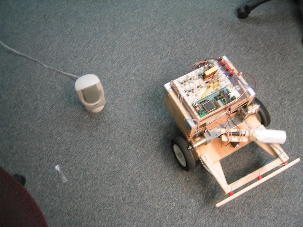
1 Sound-Seeking Robot An E155 Design Project at Harvey Mudd College (Claremont, California) December 15, 2003 Alex Utter Chris Wottawa Abstract A sound-seeking-robot was designed to navigate towards a specific alternating tone. The robot utilized analog signal processing, a PIC microcontroller, and an FPGA to locate and move towards its goal. The resulting robot was unable to reliably accomlish this task. The robot was able to identify the signal and locate it along a line, but was plagued by mechanical problems and frequently moved in precisely the opposite of the intended direction.
2 Table of Contents Section Page 1. Introduction Motivation and Applications Objectives Design Overview Digital Components and Functions 4 2. New Hardware Microphone Servomotor Robot Chassis Motor / Wheel Configuration H-Bridge 5 3. Schematics Analog Signal Processing Power Supply PIC / FPGA Interface 6 4. Microcontroller Design 6 5. FPGA Design 8 6. Results Testing Procedure Testing Results Future Improvements References Parts List 12 Appendix A: Robot Images 13 Appendix B: Schematics 15 Appendix C: Verilog 18 Appendix D: PIC Assembly Code 22 Appendix E: Matlab Code 31 Summary of Figures and Tables Figure/Table Page Figure 1: Block Diagram for Sound-seeking Robot 4 Figure 2: Robot chassis 6 Figure 3: Motor drive system 6 Table 1: PIC Microcontroller Pinout 8 Figure 4: Navigation Algorithm 8 Table 2: FPGA Pinout 9 Figure 5: Tone intensities 10 Table 3: Additional Parts and Budget 12 2
3 1. Introduction 1.1. Motivation and Applications Our final project was a sound-seeking mobile robot capable of locating and moving towards a specific sound signal. This project was chosen because it used many of the aspects of robotic navigation and electromechanical design applicable to more complicated robotic systems, but was still simple enough to complete in four weeks. A sound seeking robot could be used in many applications, but more importantly, the soundseeking-robot allows experimentation and testing on navigational algorithms that could be used as part of a more sophisticated, more practical robot Objectives The completed robot should be able to: Identify a specific sound signal and find the direction to the source Activate motors to rotate the robot and move towards the source Stop movement on impact with an obstruction 1.3. Design Overview The sound seeking robot contained a number of interconnected subsystems, as shown in figure 1. The sound that the robot sought was a signal that alternated between a 440 Hz tone and a 600 Hz tone at a rate of 4 Hz. This tone was chosen because a signal that alternates between two pure tones is easily processed and unlikely to be found from any undesired noise source. Therefore it would be easy to identify even in a relatively noisy environment. The robot used a directional microphone to detect this signal and determine a bearing to its source. This microphone was mounted on a servomotor which rotated in a search pattern. 3
4 Analog band-pass filters with envelope detectors processed the microphone signal, and the PIC microcontroller sampled these envelopes to determine whether the desired sound signal has been found. For locomotion, the robot used two drive wheels with one motor each in a tank-style configuration, plus a caster wheel for support. These motors were driven by the FPGA through an H- bridge for reversible control. As the robot moved, it continued to use the microphone to get updated, more-accurate bearings on the source, adjusting its path accordingly. If it collided with an obstruction in its path, it simply stopped movement altogether. Collisions were detected using a front bumper that depressed a switch Digital Components and Functions PIC Functions: A/D Conversion of sound signal envelopes (envelopes found using analog electronics) Sound signal identification PWM control of microphone-pointing servo Top level navigation logic Output status and A/D information FPGA Functions: Motor control logic Bumper switch debounce and collision detection logic 2. New Hardware In addition to the PIC Microcontroller and the Xilinx FPGA, additional hardware was needed to complete the sound-seeking robot. 2.1 Microphone The microphone used was a standard consumer microphone for home audio use, and therefore included most of the circuitry necessary to output the sound signal. Before acquiring this microphone, we attempted to use a cartiridge microphone, which did not include the appropriate power and signal separation circuits. Despite many attempts to recreate the circuit shown in the cartridge microphone's datasheet, we were unable to ever detect any sort of useful signal; we believe that the microphones obtained from the stockroom may have "expired", having been left unused for so long that they lost the internal electrical charges necessary for proper functionality of electret microphones. The commercially purchased microphone worked flawlessly from the moment we connected it to our processing circuit. To increase the directionality of our microphone to desired levels, a long paper tube was 2.2 Servomotor For rapid and accurate pointing of the microphone independent of the movement of the robot, a servomotor was added. Standard hobby servomotors require power and a pulse-width-modulated signal that corresponds to a specific armature position. Once given a PWM command, a servomotor attempts to rotate to the specified angle and maintains that angle as long as the command is maintained. This robot's servomotor had a PWM period of 30 ms and a rotation range of about 180 ; periods corresponding to specific angles were determined empirically. 4
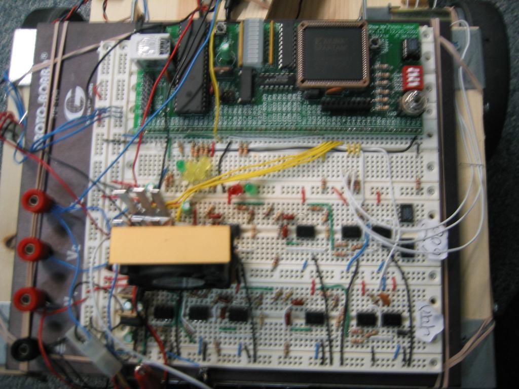
5 2.3 Robot Chassis A photo of the robot is shown in figure 2. Additional images of the finished robot chassis is shown in Appendix A. The motors were connected to angle brackets with screws, through cuts in the angle brackets that allow easy adjustment of the motor s vertical position. The holding area of the robot had two floors. Three batteries were mounted on the lower floor. The analog signal processors, PIC, and FPGA were all mounted onto a Protoboard which rested securely on the top floor of the robot s chassis. The microphone and servomotor setup at the front of the robot allowed it to quickly point the microphone in different directions in order to best Figure 2: Robot chassis determine the location of the sound source. In front of the microphone and servo was a bumper; the front bumper needed to extend past the end of the microphone and past the wheels. When the robot came into contact with an object, the bumper closed a switch which was connected to the FPGA. 2.4 Motor / Wheel Configuration The motor gears are positioned directly against the wheels so that friction between the gear and the wheel moves the robot forward or backward, as shown in figure 3. The front two wheels are driven with motors and the back wheel is a free moving caster. For the robot to turn, one wheel needs to be driven forward and the other backwards. To move forward, both wheels are driven forward. 2.5 H-Bridge In order to drive the large currents needed by the motors using the the small currents suppliable by the FPGA, the robot uses a device known as an H-bridge. The H-bridge allows for logic-level control of large currents and voltages, and is configured to drive the motor both forward and in reverse. The H-bridge used, the L293DNE, was a dual H-bridge with internal diodes that limit voltages developed by the motor that could damage the PIC and FPGA. 3. Schematics Detailed electrical schematics are available in Appendix B. Descriptions of the circuits diagrammed follow: 3.1 Analog Signal Processing The microphone output was fed into an amplifier which acted as a voltage follower and had a gain of 30. (The voltage follower was needed to supplement the microphone's very low output currents.) The amplified output was fed into a parallel pair of band pass filters with pass frequencies of 440 and 600 Hz and bandwidths of ± 20Hz, to effectively screen out background noise while still allowing adequate signal change rates. In series with each filter was a precision full wave rectifier and low-pass filter with time constant of 10 ms, to sense the signal envelope in each band. The output from each envelope detector is periodically sampled by the PIC's built-in A/D converters. 3.2 Power Supply The sound-following robot had a large number of digital, analog, and mechanical components, each with Figure 3: Motor drive system 5
6 unique voltage and current requirements. As a result, the power systems of the robot were very complex, requiring three separate batteries and five separate power buses. The utility board and analog processing circuits were powered by a 12V battery. The utility board operated between 0 and +5V, maintained by an L7805CV voltage regulator. The analog signal processing circuits used operational amplifiers that normally require a ground, positive supply, and negative supply. Unfortunately, the analog outputs were required to operate in the same voltage range as the utility board, to allow the PIC's A/D converters to operate properly. As such, all analog signals used a "virtual ground" as the zero signal, which was maintained at +5V relative to the battery's ground. The op-amps then received 0 and +10V for their negative and positive supplies, respectively; the +10V power wass supplied by a pair of L7805CV regulators connected in series. To put the output in the right range, the analog envelope finders were operated in reverse, outputing the virtual ground of +5V for zero signal, with output voltage dropping for a stronger signal. All devices operated on the 0, +5V, and +10V supplies were sensitive to ripple, so all supply voltages were linked capacitively to maintain constant relative voltages in the face of rapidly fluctuating current loads. A second, 6V battery supplied the microphone-pointing servomotor and a cooling fan. Originally, the servomotor was powered off of the +5V supply for the utility board, but the motor drew so much current that the utility board would frequently brown-out due to voltage sag, so it was moved to a separate supply. No regulation was needed because the motor was not sensitive to small voltage fluctuations. Finally, the main drive motors were driven by a separate 12V battery. When running, the motors usually drew several amps of current, which would cause unacceptable voltage sag in the other 12V battery. These motors were originally powered by the 6V battery, but as the robot's weight increased, more power was needed to overcome static friction. Increasing the motor supply voltage to 12V battery was adequate to drive the motors. 3.3 PIC / FPGA interface The division of tasks between the FPGA and the PIC required three signals connecting the two chips. The first was the motor control byte, which was sent serially over the PIC's SPI interface. The SPI interface consisted of serial clock and serial output signals which were connected to an appropriate decoder on the FPGA, as well as a serial input signal which was connected to ground, since there was no need for corresponding FPGA to PIC messaging. The second signal was the bumped-flag, which was triggered and held high whenever the robot ran into an obstacle and depressed the bumper switches. Whenever the FPGA detected a bumper press, it would stop the drive motors and set the flag high until reset. This signal triggered a highpriority interrupt in the PIC, which stopped all other motors and sent the PIC into sleep mode until it was reset. The PIC's initialization routine triggered a reset in the FPGA (thus resetting the bumped flag); the reset wire is the third PIC to FPGA signal. 4. Microcontroller Design The functions of the PIC microcontroller were: A/D Conversion of sound signal envelopes (envelopes found using analog electronics) Sound signal identification PWM control of microphone-pointing servo Top level navigation logic Output robot status and A/D information to LED indicators The PIC assembly code was written in one module, called "navigation.asm", given in Appendix D. This PIC code does the following: 1) Outputs a PWM signal to the microphone-pointing servomotor 6
7 2) Reads the two Analog inputs and a reference voltage, and does A/D conversions 3) For each quarter second set of A/D results, computes TempResult (see below) 4) Uses TempResult score to send one of four possible motor control bytes to the FPGA. These control bytes consist of two signed four bit integers (-7 to +7) which correspond to the forward and backward speed of the left and right motors. The left motor s speed is specified by the first four bits, and the right motor s speed is specified by the last four bits. The most important control bytes are: 0x97 (turn left), 0x79 (turn right), 0x77 (go straight), or 0x00 (stop). 5) Receives the bumped input from the FPGA. If high, this triggers an interrupt. The PIC outputs a control byte to the FPGA that says the robot should stop moving, and then goes into sleep mode. RC6 is pulled high, turning on the red indicator light. The following table gives the final pinout for the PIC microcontroller. Table 1: PIC Microcontroller Pinout Signal From / To I/O Pin Used 440Hz Analog Input Analog Signal Processor (440Hz) Input AN0 / RA0 600 Hz Analog Input Analog Signal Processor (600Hz) Input AN1 / RA1 A/D Voltage Reference Voltage Reference Circuit Input AN3 / RA3 Motor Control Byte FPGA Output SPO / RC5 Serial Clock FPGA Output SCLK / RC3 Bumped? FPGA Input INT0 / RB0 Pulse Microphone Servomotor Output CCP1 / RC2 Bumped Indicator Red LED Output RC6 Normal Operation Green LED Output RC7 Turning/Going Straight Green LED Output RA5 Temp Result [9] Yellow LED Output RB2 Temp Result [8] Yellow LED Output RB3 Temp Result [7] Yellow LED Output RB4 Temp Result [6] Yellow LED Output RB5 Reset FPGA FPGA Output RB1 Navigation was accomplished by a sort of state machine, as shown in figure 4. The robot starts in the "turn left" state. It continually turned left until the microphone detects a decrease in volume, indicating that it had found the sound source and turned slightly too far. (The "turn right" state functioned in the same manner.) The robot then went to the "move forward" state, and periodically scans regions directly ahead, slightly to the left, and slightly to the right. It continued to move forward until either the right or left sectors showed a higher signal amplitude, in which case it began turning in the direction of the strongest signal. Movement was performed between microphone sampling times, to reduce the noise caused by motor vibrations. Input consisted of the two analog signal amplitudes (which started at 5.0V for no signal and dropped to as low as about 3.0 V for a very strong sound signal), and a "bumped" pin that was pulled high if the robot collided with an obstacle (indicating that the robot should stop as quickly as possible.) Output consisted of an SPI link for sending a motor control byte (MCB), a green LED that 7
8 flashed to indicate normal operation, a green LED that turned on during forward motion, four yellow LEDS that represented the four most significant bits of the TempResult and a red LED that turned on if an emergency stop was initiated. The motor control byte consisted of two, signed 4-bit numbers (-8 to 7), corresponding to the speed of the left and right motors. The maximum forward speed was +7, and - 7 was the maximum reverse speed; -8 is an error code. To find the strongest signal, for every quarter second set of A/D samples, the largest 440Hz value and its corresponding 600Hz value were stored as well as the largest 600Hz value and its corresponding 440Hz value. The strongest signal was defined as the signal that has the largest result to the following equation: TempResult = MAX MAX COR COR440 This way, the robot was more sensitive to the alternating tone and not as sensitive to other noises with high 440 Hz or high 600 Hz components. In addition, if none of the TempResults were above a configurable threshold, the robot turned in counterclockwise circles until it found a strong enough signal. The pulse widths and corresponding motor control bytes were stored in a table so that it would be easier to add and adjust more microphone sample directions as needed. 5. FPGA Design The field programmable gate array (FPGA) translated motor control information into pulsewidth-modulated commands for the H-bridge, and debounced the bumper switches. The pinout of the FPGA is shown in Table 2. Table 2: FPGA Pinout Signal From / To I/O Pin Used Bumped PIC Output P77 motorout[3] H-Bridge Output P40 motorout[2] H-Bridge Output P39 motorout[1] H-Bridge Output P38 motorout[0] H-Bridge Output P37 leds[7] LED Array Output P10 leds[6] LED Array Output P9 leds[5] LED Array Output P8 leds[4] LED Array Output P7 leds[3] LED Array Output P6 leds[2] LED Array Output P5 leds[1] LED Array Output P4 leds[0] LED Array Output P3 serin PIC Input P82 serclk PIC Input P35 reset PIC Input P62 clk Clock Input P13 bumpersw[2] Bumper switch Input P46 bumpersw[1] Bumper switch Input P45 bumpersw[0] Bumper switch Input P44 The motor control byte was periodically sent over the PIC's SPI interface, and received by a shift-register on the FPGA. This shift register counted incoming bits and updated a separate output register each time a complete byte was received. This output register allowed other modules to receive a clean and consistent motor-control-byte even during the transmission of the subsequent control byte. The motor control byte consisted of a pair of four bit, two's complement binary numbers. For each number, the range of -7 to +7 corresponded to requests for speeds between full speed reverse and 8

9 full speed forward, with 0 requesting a stop. The remaining possible input, -8, was reserved as a possible error code but was unused in this version of the robot. The four most significant bits controlled the left motor, and the four least significant bits controlled the right motor. These speed requests were decoded into a corresponding PWM signal for the H-bridge, with a 14 ms cycle period broken into 7 segments of 2 ms each. The motors were activated in the requested direction for a number of segments equal to the requested speed, and stopped for the rest. Later experimentation showed that these speeds were from from linear, and that the motors would fail to start at all but the highest speed settings. Future versions of the robot might send a full speed signal to start the motors and drop the speed for more precise navigation, but these features were not needed in this version of the robot. Bumper switch debouncing was accomplished by sampling the switch output on every cycle. If any switch was depressed for two subsequent cycles (1 microsecond), then the bumped flag was pulled high. This flag signaled the PIC to stop all motion, and also caused the FPGA to stop the drive motors without waiting for a stop command from the PIC; a faster stop means less likelihood of damage due to a collision. Verilog for the modules responsible for these operations is given in Appendix C. 6. Results 6.1. Testing Procedure The sound source was generated and saved in a.wav file. It was made using Matlab, and consists of a tone that alternates between 440 Hz and 600 Hz, cycling at a frequency of 4Hz. (The code for generating signals of this type is included in Appendix E.) This sound was played back through a personal computer. Most tests took place in the Microprocessors lab. Several tests were run with the robot positioned at different locations from one to eight feet away from the sound source. For each location, several tests were run with the robot initially facing in different directions relative to the source. Tests were completed successfully if the robot bumped into the sound source, or unsuccessfully if the robot bumped into another object or strayed too far away from the sound source (nine or more feet away) Testing Results The testing showed that the robot usually navigated to a location near the sound source, and occasionally navigated well enough to bump into the sound source, but this behavior was not very reliable. In most cases, once the robot was close to the sound and facing towards it, having acquired a solid "lock" on the sound's bearing, it moved towards the sound accurately enough to successfully contact the speaker. Ranges under one or two feet worked the most reliably. Occasionally, the robot "missed" and overshot the speaker, ending up in a sort of "orbit" around the sound source, but this problem was not as significant as many others. Occasionally, the robot read an incorrect bearing to the sound source. The robot rarely went in a direction perpendicular to the sound source, instead favoring going directly towards or directly away. This behavior was the result of some combination of undesired microphone sensitivity, flaws in the robot's turning algorithm, and sound reflections. For a given source position, the microphone was most "sensitive" to the sound when facing either directly away or directly towards the sound. (See figure 5, where green represents weak signals and red represents strong signals.) This rearward sensitivity could have been due to a problem with our "unidirectional" microphone or with detection of reflections off of nearby walls. In any case, the sensitivity had an adverse effect on the robot's behavior. When the robot was facing straight ahead, and had locked on Figure 5: Tone intensities 9
10 to the signal, it continued towards it as much as the sticky left wheel allowed. However, if the sound source was not directly in front of the robot, problems arose. Suppose the robot is currently facing section B in the figure, such that the tone is just outside of the microphone's range to the right and the robot could not yet hear anything. According to the algorithm, this means that the robot should turn left. It would scan through section C, and realize that the strength of the signal has increased, though it would not stop turning until the signal intensity began to decrease. This would happen when the robot turns through the border between sections C and D. The robot would then think that the signal is in section C, so it would turn back one step and go straight ahead, directly away from the source. The robot effectively moves towards the local maxima in signal intensity, unaware of the stronger signal behind it. Another significant problem involved the drive system. The motors usually maintained adequate traction with the wheels to accurately turn left or right. When attempting to move straight, however, the left motor had trouble breaking the static friction of the left wheel on the ground, so that the robot would veer to the left instead of moving forward. The inconsistency between the motor commands and the robot's behavior frequently caused the robot to become confused. Once confused, the robot rarely re-acquired its lock on the sound Future Improvements There are a number of improvements that could be made to simplify the current robot design as well as improve the speed and reliability of its performance. The first obvious area in need of improvement is the motor mounting design. Even if the robot could perfectly sense the alternating tone and ignore arbitrary amounts of noise, if the wheels do not respond appropriately, the robot is not going to reliably succeed in its task. While this current motor design is very simple to build and works well under some applications, it would be better to use a consistently reliable and precise design. One such idea is to use a gear box to increase the motor output torque, and mount the output shaft directly to the axle of the wheels. This design would eliminate slippage and would probably greatly boost the motor's efficiency. The motors in this design were chosen because of their availability and price (Engineering stock room and free), with little regard for their appropriateness. It is very possible that there are more expensive motors which may be more difficult to find that are more suitable for this application. Problems with rearward sensitivity to the signal (due to problems with the microphone and sound reflections) could be resolved by mounting an additional microphone, pointing opposite the direction of the original microphone. This rear-pointing microphone could then detect the stronger signal, indicating that the forward signal is not the correct one to follow. Unfortunately, this microphone would require an additional complete set of analog processing filters, making it very useful but impractical. Another problem with the robot is its sensitivity to sounds which are not the intended signal. Stomping, clapping, vibrations, and even talking will often fool the robot into thinking that it has detected the alternating tone signal. This phenomenon is at least partly due to our processing system in the PIC, which uses only the maximum detected 440 Hz signal, the maximum of the 600 Hz signal, and the corresponding opposite signals. Since it does not take into account any of the other hundreds or thousands of data points at all, it discards a great deal of useful data. In addition, the "maximum" signal may frequently be due to a simple glitch or one-time spike, rendering the system very susceptible to random noise. The fact that the algorithm effectively uses the derivative of these maximums for its turning algorithm makes matters worse, since derivatives inherently accentuate highfrequency noise. One way to solve these problems is to use more sophisticated processing algorithms in software. One such algorithm takes the mean of the data recorded over a quarter second, then averages values above and below this mean for each frequency band, computing the ranking score from these 10
11 averages instead of the maximum values. This method would be complicated by the PIC's lack of a divide command, which makes it impossible to take the average of an variable quantity of values. A simpler method might be to enhance the robot's analog signal processing. The current circuitry does not take advantage of the fact that the signal alternates frequencies at a rate of 4 Hz. Rather than sampling the output of the envelope detectors, an improved robot might include a 4 Hz band pass of the difference between the two envelope outputs, and then find the envelope of this signal. Any noise except our signal is very, very unlikely to alternate between 440 and 600 Hz at a rate of 4 Hz, so this filter would block nearly everything except the desired signal. With this filter in place, the PIC would only need to sample a single output signal which directly corresponds to the intensity of the desired signal. In addition to the problems listed, a more useful robot of this type would need to be able to navigate through environments more complex than a large, flat, open room. Once navigation towards a sound is adequately refined, an important upgrade to the robot would include the ability to navigate around simple obstacles. 7. References Brown, Jim. "Brief H-Bridge Theory of Operation." 1998 April. Doshi, Rishin. "Friction Drive Analysis" Spring. Fortner. "Laboratory Electronics ". Date unknown. Mishra, Rohit and Wang, Mark. "Musical Instrument Tuner" National Semiconductor. "LM741 Operational Amplifier" August. Purdie, Ian C. "Active Bandpass Filters" ST Micro. "L293D Push-Pull Four Channel Driver with Diodes" July. ST Micro. "L7800 Series Positive Voltage Regulators" November. 11
12 8. Parts List Table 3. Additional Parts and Budget Part Source Vendor Part # Price Wood East Dorm, HMC Microphone Radio Shack ---- $9.99 Servomotor ---- Hobbico CS Cooling Fan ---- Topower V Battery Radio Shack Eveready V Rechargeable Battery MarVac Electronics PS-670 $ V Rechargeable Battery MarVac Electronics PS-1270F1 $ " Wheels (x2) Home Depot ---- $9.92 Caster Home Depot ---- $4.97 Angle Brackets Home Depot ---- $6.63 Screws, Washers, Nuts, Bolts Home Depot ---- $6.54 Motors (x2) Stock Bühler ---- Switches (x3) Stock Rubber Bands Operational Amplifiers (x10) Stock HA H-Bridge DigiKey L293DNE ---- Diodes (x2) Stock 1N4002GP ---- Total Cost $


13 Appendix A: Robot Pictures 13
14 14
15 Appendix B: Schematics VMotor VServo 12V 10V J1 J2 J3 V3 12V V1 6V V2 12V C1 10uF Power Suply U1 LM7805CT Vreg IN OUT Fan and Heatsink M1 LM7805CT Vreg U2 IN OUT U3 LM7805CT Vreg IN OUT C3 10uF C2 10uF C5 10uF VirtualGround 5V VHigh 10V 15
16 U U R3 390kOhm_5% C3 10nF C2 10nF C5 10nF C4 10nF R4 820kOhm_5% R8 820kOhm_5% R6 390kOhm_5% R7 1.6kOhm_5% R5 1.6kOhm_5% U U R15 4.7kOhm_5% R16 4.7kOhm_5% R17 4.7kOhm_5% R18 150kOhm_5% C10 100nF Out440 MicInPos U R20 10kOhm_5% U U R9 390kOhm_5% C6 10nF C7 10nF C8 10nF C9 10nF R10 820kOhm_5% R11 820kOhm_5% R12 390kOhm_5% U U R21 4.7kOhm_5% R22 4.7kOhm_5% R23 4.7kOhm_5% R24 150kOhm_5% C11 100nF Out600 R14 887Ohm_1% R13 887Ohm_1% D3 1N4002GP D1 1N4002GP MicInNeg 10V VHigh 5V VirtualGround 10V VHigh 5V VirtualGround U R1 330Ohm_5% R2 270kOhm_5% Out 440 Hz Out 600 Hz Analog Signal Processor 16
17 In440_RA0 In600_RA1 M1 LED_Blinky LED_Bumped LED_Result9 M2 12V VMotor 5V VirtualGround HBridge DIP VLogic In4 Out4 Gnd Gnd Out3 In3 3,4 En 1,2 En In1 Out1 Gnd Gnd Out2 In2 VMotor MotorOut1_P38 MotorOut0_P37 MotorOut2_P39 MotorOut3_P40 5V VirtualGround PIC U12 UNDCD_BARGRAPH J4 FPGA <- Out In -> leds7_p10 R19 330Ohm_5% leds6_p9 leds5_p8 leds4_p7 leds3_p6 leds2_p5 leds1_p4 leds0_p3 5V VirtualGround 5V VirtualGround R26 1.0kOhm_5% J5 J6 bumpersw0_p44 bumpersw1_p45 bumpersw2_p46 Clock_2MHz clk_p13 serclk_p35 reset_p62 serin_p82 bumped_p77 SPI_In_RC4 SPI_Out_RC5 SPI_Clk_RC3 Bumper RB0_HPInterrupt R37 4.7kOhm_5% resetfpga_rb1 Clock 4.7kOhm_5% 330Ohm_5% LED_Forward LED_Result8 LED_Result7 LED_Result6 330Ohm_5% 330Ohm_5% 330Ohm_5% 330Ohm_5% 330Ohm_5% 330Ohm_5% RB2 RB3 RB4 RB5 RA5 RC7 PwrPIC GndPIC GndFPGA PwrFPGA 5V VirtualGround 10V VHigh R47 8.2kOhm_5% R48 8.2kOhm_5% C15 10uF VRef_RA3 ServoPWM_RC2 Servo_Data Servo_Gnd Servo_VPlus 6V VServo PIC & FPGA & Accessories RC6 17
18 Appendix C: Verilog All six Verilog modules for the sound-seeking robot were written by Alex Utter and Chris Wottawa, from 2003/11/21 through 2003/12/15. // Sound-seeking robot, top-level module // Takes a motor control byte from the PIC, and translates that into PWM // control signals for the H-bridge. Also debounces the bumper switches and // reports the "bumped" flag back to the PIC. module soundbot(clk, reset, serclk, serin, bumpersw, motorout, bumped, leds, slowclk); input clk, reset; input serin, serclk; input [2:0] bumpersw; output [3:0] motorout; output bumped; output [7:0] leds; output slowclk; wire slowclk; wire [7:0] command; wire bumped; // Get serial input from PIC // When a byte is ready, set that as the current command. ShiftReg serin(serclk, reset, serin, command); //assign command = 8'b ; assign leds[7:0] = command[7:0]; //assign leds[7:0] = {~slowclk, slowclk, bumped&(~slowclk), bumped&slowclk, // motorout[3], motorout[2], motorout[1], motorout[0]}; // If bumper ever touched, set bumped flag // Attempt to filter erroneous inputs SwitchDebounce bumperdebounce(clk, reset, bumpersw, bumped, slowclk); // Convert current command to PWM out ClockDiv clockdiv(clk, reset, slowclk); MotorControl motorcontrol(slowclk, reset, command, bumped, motorout); endmodule // A standard clock-divider. This one divides by 4000, to convert the 2 MHz // clock to a more useful timescale at about 500 Hz. module ClockDiv(clk,reset,slowClk); input clk; input reset; output slowclk; // Goal is to convert 2 Mhz clock to one with a period ~2 ms. // So divide by 4000 reg [15:0] counter; wire [15:0] nextcounter; // Increment counter assign nextcounter = (counter==16'd3999)? 0 : (counter + 1); always@(posedge clk or posedge reset) begin if(reset) counter <= 0; else counter <= nextcounter; end // If more than half done, slow-clock is high assign slowclk = counter > 16'd1999; 18
19 endmodule // This module takes in a motor-control byte, and puts out a PWM signal for // the H-bridge. The MCB is split into two 4-bit numbers in two's // complement form. Full reverse is -7, stop is 0, and full forward is +7; // -8 is reserved for later use as an error code. module MotorControl(clk,reset,commandIn,fastStop,commandOut); input [7:0] commandin; output [3:0] commandout; input faststop; // Emergency stop input clk; input reset; reg [6:0] L1, L2; reg [6:0] R1, R2; reg [2:0] counter; wire [6:0] nextl1, nextl2; wire [6:0] nextr1, nextr2; wire [2:0] nextcounter; // Decode -7 to +7 throttle to 7 PWM outputs ThrottleDecode throttledecodel(commandin[7:4], nextl1, nextl2); ThrottleDecode throttledecoder(commandin[3:0], nextr1, nextr2); // Keep counter going to count every 7 clock ticks assign nextcounter = (counter == 6)? 0 : counter + 1; always@(posedge clk or posedge reset) begin if(reset) counter <= 3'b000; else counter <= nextcounter; end // At counter = 0, insert next command set // Otherwise, act as a shift register always@(posedge clk or posedge reset) begin if(reset) begin L1 <= 7'b0; L2 <= 7'b0; R1 <= 7'b0; R2 <= 7'b0; end else if(~( counter)) begin L1 <= nextl1; L2 <= nextl2; R1 <= nextr1; R2 <= nextr2; end else begin L1 <= {L1[5:0], L1[6]}; L2 <= {L2[5:0], L2[6]}; R1 <= {R1[5:0], R1[6]}; R2 <= {R2[5:0], R2[6]}; end end // Construct the output control signal assign commandout = (faststop)? (4'b0000) : ({L1[6], L2[6], R1[6], R2[6]}); endmodule // Decodes the -7 to +7 throttle setting to a seven-segment PWM signal. // Each segment is a set period (~2 ms or so), and switches the H-bridge // to stop, forward, or reverse. Other modules cycle through the series // of seven time segments to create a PWM output. module ThrottleDecode(command,outA,outB); 19
20 input [3:0] command; output [6:0] outa; output [6:0] outb; reg [6:0] outa, outb; // Decode -7 to +7 command to forward/reverse/stop in PWM form // (-8 is an error code; stop if it is encountered) // AB bits for forward 10, reverse 01, stop 00 case(command) 4'h0: begin outa <= 7'b ; outb <= 7'b ; end 4'h1: begin outa <= 7'b ; outb <= 7'b ; end 4'h2: begin outa <= 7'b ; outb <= 7'b ; end 4'h3: begin outa <= 7'b ; outb <= 7'b ; end 4'h4: begin outa <= 7'b ; outb <= 7'b ; end 4'h5: begin outa <= 7'b ; outb <= 7'b ; end 4'h6: begin outa <= 7'b ; outb <= 7'b ; end 4'h7: begin outa <= 7'b ; outb <= 7'b ; end 4'h8: begin outa <= 7'b ; // -8 = error outb <= 7'b ; end 4'h9: begin outa <= 7'b ; // -7 outb <= 7'b ; end 4'hA: begin outa <= 7'b ; // -6 outb <= 7'b ; end 4'hB: begin outa <= 7'b ; // -5 outb <= 7'b ; end 4'hC: begin outa <= 7'b ; // -4 outb <= 7'b ; end 4'hD: begin outa <= 7'b ; // -3 outb <= 7'b ; end 4'hE: begin outa <= 7'b ; // -2 outb <= 7'b ; end 4'hF: begin outa <= 7'b ; // -1 outb <= 7'b ; end endcase endmodule // A modified shift-register, for serial communication with the PIC. // The PIC periodically sends a motor control byte via a single serial // data pin and a serial clock. A shift register holds this sequence of // bits until all 8 bits have been received. It then outputs that sequence // of 8 bits until another set of 8 bits has been received, and so on. module ShiftReg(clk,reset,d,out); input clk, reset; input d; output [7:0] out; reg [2:0] count; reg [7:0] temp; reg [7:0] out; wire [2:0] nextcount; wire [7:0] nexttemp; assign nextcount = count + 1; assign nexttemp = {temp[6:0], d}; 20
21 clk or posedge reset) if(reset) begin count <= 0; temp <= 0; out <= 0; end else begin count <= nextcount; temp <= nexttemp; if(nextcount == 0) out <= nexttemp; end endmodule // Debounce the bumper switches by ensuring that the "bumped" flag is not // set unless a single switch has been held down for at least two // successive clock cycles (1 microsecond). If this occurs, set the // bumped flag and hold it high until the FPGA is reset. module SwitchDebounce(clk,reset,in,out, slowclk); input clk; input reset; input [2:0] in; input slowclk; output out; reg [2:0] previn; wire prevout; reg out; reg startupdelay; assign prevout = out; always@(posedge slowclk or posedge reset) begin if(reset) startupdelay <= 0; else startupdelay <= 1; end always@(posedge clk or posedge reset) begin if(reset) begin previn <= 0; out <= 0; end else begin previn <= in; // Output high if any switch held for two cycles out <= startupdelay & ( prevout ( (previn & in)) ); end end endmodule 21
22 Appendix D: PIC assembly code ; navigation.asm ; Written 2003/11/ /12/15 ; autter@hmc.edu ; cwottawa@hmc.edu ; ; Sound Seeking Robot Navigation ; ; Navigation was accomplished by a sort of state machine. The robot ; starts in the "turn left" state. It continually turns left until the ; microphone detects a decrease in volume, indicating that it has found ; the sound source and turned slightly too far. (The "turn right" state ; functions in the same manner.) The robot then goes to the "move ; forward" state, and periodically scans regions directly ahead, ; slightly to the left, and slightly to the right. It continues to move ; forward until either the right or left sectors show a higher signal ; amplitude, in which case it begins turning in the direction of the ; strongest signal. Input consists of the two analog signal amplitudes ; (which start at 5.0V for no signal and drop to as low as about 3.0 V ; for a very strong sound signal), and a "bumped" pin that is pulled ; high if the robot collides with an obstacle (indicating that the robot ; should stop as fast as possible.) Output consists of an SPI link for ; sending a motor control byte (MCB), a green LED that flashes to ; indicate normal operation, a green LED that turns on during forward ; motion, four yellow LEDS that represent the four most significant bits ; of the TempResult and a red LED that turns on if an emergency stop is ; initiated. The motor control byte consists of two, signed 4-bit ; numbers (-8 to 7), corresponding to the speed of the left and right ; motors. The maximum forward speed is +7, and -7 is the maximum ; reverse speed; -8 is an error code. ; ; use the 18F452 PIC Microprocessor LIST p=18f452 include "p18f452.inc" ; allocate variables MCB equ 0x00 ; store current MCB to be sent to FPGA ; NOTE: PORTD is not being used by the FPGA now. ; need high and low, so can use 10-bit A/D MAX440L equ 0x01 ; store maximum 440 result MAX440H equ 0x11 COR600L equ 0x02 ; store corresponding 600 result COR600H equ 0x12 MAX600L equ 0x03 ; store maximum 600 result MAX600H equ 0x13 COR440L equ 0x04 ; store corresponding 440 result COR440H equ 0x14 PRV440L equ 0x05 ; store previous samples PRV440H equ 0x15 ; this is used for getting corresponding PRV600L equ 0x06 ; amplitude of other tone. PRV600H equ 0x16 MAXSUML equ 0x07 MAXSUMH equ 0x17 CORSUML equ 0x08 CORSUMH equ 0x18 TEMPRESL equ 0x09 TEMPRESH equ 0x19 PRVRESL equ 0x0A PRVRESH equ 0x1A ; MAXSUM = MAX440 + MAX600 ; CORSUM = COR440 + COR600 ; TEMPRES = MAXSUM - CORSUM ; store previous result (only if turning) 22
23 MAXRESL equ 0x0B MAXRESH equ 0x1B ; store maximum result. ZERO equ 0x30 ; contains 0 AL equ 0x31 AH equ 0x41 BL equ 0x32 BH equ 0x42 BisBigger equ 0x33 timerdone equ 0x0D ; 16-bit compare registers ; flag for 16-bit compare (0th bit only) ; flag, use bit 0, assert if TMR0 is done ; counting ; Motor Control Byte (MCB) to be sent serially ; Output protocol [Left Motor Thrust(4)][Right Motor Thrust(4)] ; using signed 2's complement numbers (negative means go backwards) goleft equ 0x97 goright equ 0x79 gostraight equ 0x77 gostop equ 0x00 ; Pulse Widths for Microphone Servo control midp equ 0x28 ; middle pulse leftp equ 0x1A ; left rightp equ 0x38 midpl equ 0x27 ; right ; slightly left of middle midpr equ 0x29 ; slightly right of middle ; threshold value thresh equ 0x30 ; timer 0 starting values ; the lower the number the greater the time. ; When called for a delay, etc., the timer will be loaded with ; the given values in both the high and low counter registers. ; Don't use 0x00, or 0x80, because of PWM conflicts. timeradrecord equ 0xD7 ; time to record a given A/D series timerservowait equ 0xDB ; time to wait for the microphone servo timermotorforward equ 0xB0 ; time to allow forward movement before ; stopping and taking more samples timermotorturn equ 0xE8 ; time for turning before stopping ; store servo positions and corresponding MCB in table org 0x400 DB midp,gostraight,leftp,goleft,rightp,goright,0,0 ; begin main program org 0 bra setup org 0x08 bra bumped org 0x18 bra lowp ; being bumped is high priority ; low priority finished collecting A/D ; or PWM is done. org 0x30 setup ; I/O configuration setf TRISA clrf TRISB bsf PORTB,1 ; use RA0, RA1 for A/D input. RA3 for Vref ; use RB1 for FPGA reset. ; reset the FPGA 23
24 setf TRISC bsf TRISB,0 bcf TRISB,2 bcf TRISB,3 bcf TRISB,4 bcf TRISB,5 bcf TRISC,3 bcf TRISC,5 bcf TRISC,2 bcf TRISC,6 bcf TRISC,7 bcf TRISA,5 bcf PORTB,1 ; use RB0 for INT0 (Bumped?) ; yellow LEDs for TEMPRES ; use RB2-RB5 ; use RC3 for SCLK, ; use RC5 for SPO ; use RC2 for Pulse to Servo ; green LED, normal operation, toggle on ; each compute ; red LED, bumped indicator ; yellow LED, straight or turning? ; clear FPGA reset setf TRISD ; PORTD as input to not mess up FPGA ; ; clrf TRISD clrf PORTD ; output to LEDs to help debug ; bsf PORTD,6 ; pattern to indicate initial LED status bcf PORTC,6 ; green LED, normal op, initially off ; A/D configuration (see chapter 17 in PIC manual) movlw 0x85 movwf ADCON1 ; right justified, Fosc/2, AN0 and AN1 input ; Vref -> AN3 movlw 0x01 ; power up, Fosc/2, initially use ch0 movwf ADCON0 ; don't start taking data just yet ; SPI configuration clrf SSPCON1 bsf SSPCON1,5 ; for SPI need to clear [4:0] ; set SSPEN (turn on SPI) bcf SSPSTAT,7 ; must be cleared on SPI slave mode bsf SSPSTAT, 6 ; data on rising edge of clock ; PWM configuration movlw 0xFF movwf PR2 movlw leftp movwf CCPR1L movlw 0x0C movwf CCP1CON ; set PWM period (change to 11 ms) ; set default PWM duty cycle ; always start in the center ; PWM mode ; Interrupt configuration (see chapter 8 of PIC manual) ; Interrupts are used for bumped condition and PWM module bsf RCON,7 movlw 0xF0 ; enable priority levels ; enable interrupts, timer and external movwf INTCON ; and clear all interrupt flags bcf INTCON2,2 bsf INTCON2,6 ; timer0 low priority ; falling edge of INT0 bcf PIR1,1 ; clear timer2 interrupt flag bsf PIE1,1 bcf IPR1,1 ; enable timer2 interrupts ; timer 2 interrupt low priority ; Timer2 Configuration (see chapter 12 of PIC manual) ; Timer2 is used in PWM module movlw 0x06 ; configure TMR2 (turn on, 16:1 prescale) movwf T2CON ; Timer0 used for A/D conversions movlw 0x84 ; enable, 16-bit, internal clock movwf T0CON ; Use prescale(2:0) to set length of time ; to wait and then sample ; (1:8 is about one second) ; send range to servo to prevent freezing on start up. movlw leftp movwf CCPR1L movlw timerservowait call delayawhile 24
25 movlw rightp movwf CCPR1L movlw timerservowait call delayawhile movlw midp movwf CCPR1L movlw goleft movwf MCB ; initially go left ; movwf PORTD ; movwf SSPBUF movlw 0x04 ; send MCB movwf TBLPTRH ; initialize table pointer to clrf TBLPTRU movlw leftp movwf CCPR1L movlw timerservowait call delayawhile call ADgo call compute movff MAXRESL,PRVRESL movff MAXRESH,PRVRESH ; move to the left and take the initial ; sample, so that we start in a valid state reinit clrf TBLPTRL movlw gostraight cpfseq MCB bra turnsetup ; reset defaults / table pointer clrf MAXRESH movlw thresh ; threshold value to detect tone movwf MAXRESL bsf PORTA,5 ; yellow LED on! movlw goleft ; turn left by default movwf MCB goingstraight ; if going straight, scan microphone tblrd*+ ; Pulse -> TABLAT -> W movf TABLAT,0 bz output ; send MCB out if at end of table movff TABLAT,CCPR1L ; send current desired direction PWM module movlw timerservowait call delayawhile ; wait for mic to get into position tblrd*+ ; next potential best MCB -> TABLAT call ADgo ; take a set of samples call compute ; TEMPRES = (MAX440+MAX600)-(COR440+COR600) movff TEMPRESH,AH ; set up for compare movff TEMPRESL,AL movff MAXRESH,BH movff MAXRESL,BL call compare16 ; 16-bit compare: TEMPRES > MAXRES (B)? btfsc BisBigger,0 bra goingstraight ; do this, if MAXRES bigger newmaxres ; do this, if TEMPRES bigger movff TEMPRESH,MAXRESH ; store new max movff TEMPRESL,MAXRESL movff TABLAT,MCB ; and MCB bra goingstraight output movlw gostraight ; Check if still going straight cpfseq MCB bra outputdelayturn ; If turning, use turn delay outputdelayforward movlw timermotorforward 25
26 bra outputoutput outputdelayturn movlw timermotorturn outputoutput ; movff MCB,PORTD movff MCB,SSPBUF ; display on LEDs for debugging ; Load MCB to Serial Port Buffer call delayawhile ; Wait for the time in W (turn or forward) movlw gostop movwf SSPBUF ; Then stop the motors bra reinit ; resets table pointer and defaults ; if the robot is turning, move the microphone to the middle and ; sample until the temporary result begins to go down ; recall that TEMPRES = MAX440 + MAX600 - COR440 - COR600 turnsetup movff MAXRESL,PRVRESL ; just came from forward movement movff MAXRESH,PRVRESH ; where MAXRES was the large signal clrf MAXRESH ; that caused us to turn initially bcf PORTA,5 ; Turning/Going Straight LED off! movlw thresh ; store the threshold value movwf MAXRESL ; will use previous result register movlw goleft ; check direction cpfseq MCB bra right left movlw midpl ; if turning left, send this PW bra turninit right movlw midpr ; if turning right, send this PW turninit movwf CCPR1L ; Send position to PWM out movlw timerservowait call delayawhile turn call ADgo call compute movff TEMPRESH,AH movff TEMPRESL,AL movff MAXRESH,BH movff MAXRESL,BL call compare16 btfss BisBigger,0 bra abovethreshold bra keepturning ; movff MAXRESH, TEMPRESH ; movff MAXRESL, TEMPRESL abovethreshold movff PRVRESH,BH ; Wait for mic to get into position ; set up for compare ; (MAXRES is threshold) ; 16-bit compare: TEMPRES > MAXRES (B)? ; if TEMPRES bigger, do nothing ; If TEMPRES smaller, set to threshold ; set up for compare movff PRVRESL,BL call compare16 ; 16-bit compare: TEMPRES > PREVRES (B)? btfsc BisBigger,0 bra stopturning ; do this, if PRVRES bigger keepturning ; do this, if TEMPRES bigger or equal movff TEMPRESH,PRVRESH ; store current value movff TEMPRESL,PRVRESL movff MCB,SSPBUF ; Send MCB ; movff MCB,PORTD movlw timermotorturn ; Wait a while... call delayawhile movlw gostop ;...then stop the motors movwf SSPBUF bra turn ; and continue the turning process stopturning movlw goleft ; check direction cpfseq MCB bra goleftonce ; if currently going right 26
27 gorightonce movlw goright bra goonce goleftonce movlw goleft goonce movwf SSPBUF movlw timermotorturn call delayawhile movlw gostop movwf SSPBUF movlw timermotorturn call delayawhile movlw gostraight movwf MCB bra output ; SUBROUTINES & INTERRUPTS! ; Set up the timer to trigger in a given amount of time, specified ; in the W register. (See timer constants, above) setuptimer movwf TMR0H movwf TMR0L bcf timerdone,0 ; Clear previous completion flags return ; Set up timer and busywait for 1/4 second (ish) delayawhile call setuptimer waitmore btfss timerdone,0 bra waitmore return ; the compute subroutine assumes that the MAX440, MAX600, ; COR440, and COR600 are all set accordingly. ; These values are used to compute TEMPRES compute bsf PORTB,3 ; clear external TEMPRES LEDs bsf PORTB,4 bsf PORTB,5 bsf PORTB,2 btg PORTC,7 ; Toggle the green LED; not related to ; compute, but a convenient place to do so movf MAX440L,0 ; 16-bit add: MAXSUM = MAX440 + MAX600 addwf MAX600L,0 movwf MAXSUML movf MAX440H,0 addwfc MAX600H,0 movwf MAXSUMH movf COR440L,0 ; 16-bit add: CORSUM = COR440 + COR600 addwf COR600L,0 movwf CORSUML movf COR440H,0 addwfc COR600H,0 movwf CORSUMH movf CORSUML,0 ; 16-bit sub: TEMPRES = MAXSUM - CORSUM subwf MAXSUML,0 movwf TEMPRESL movf CORSUMH,0 subwfb MAXSUMH,0 movwf TEMPRESH 27
28 btfss TEMPRESL,6 bcf PORTB,2 btfss TEMPRESL,7 bcf PORTB,3 btfss TEMPRESH,0 bcf PORTB,4 btfss TEMPRESH,1 bcf PORTB,5 ; output four most significant bits of ; to external LEDs btfss TEMPRESH,7 return clrf TEMPRESH clrf TEMPRESL ; if TEMPRES is negative, set it to zero. ; this makes 16-bit compare easier ; and negative TEMPRES will never ; be above the threshold anyway. ; movff TEMPRESL,PORTD ; display each temp result on LEDs return ; A/D subroutine (each call to this subroutine takes one "set" of ; samples and saves max440, max600, cor440, and cor600 ; max440 is the maximum value from the 440 BP filter ; cor600 is the corresponding value from the 600 BP filter ; max600 is the maximum value from the 600 BP filter ; cor440 is the corresponding value from the 440 BP filter ; a "set" of samples is defined by the values in TMR0L, and TMR0H ; when this subroutine is called. (This constant "timer" is above) ADgo clrf MAX440H ; starting a new A/D run.. clrf MAX440L ; clear out the old values clrf MAX600H clrf MAX600L clrf COR440H clrf COR440L clrf COR600H clrf COR600L clrf PRV600L clrf PRV600H clrf PRV440L clrf PRV440H movlw timeradrecord ; Set to go off in 1/4 second call setuptimer ; Initialize timer, but continue while waiting bsf ADCON0,3 bsf ADCON0,2 initialread600 btfsc ADCON0,2 bra initialread600 btg ADRESH,1 btg ADRESH,0 comf ADRESL,1 movff ADRESH,PRV600H movff ADRESL,PRV600L readad btfsc timerdone,0 return bcf ADCON0,3 bsf ADCON0,2 read440 btfsc ADCON0,2 bra read440 btg ADRESH,1 btg ADRESH,0 comf ADRESL,1 ; Start by taking an initial 600 Hz reading ; Start A/D converter ; poll A/D status ; invert first 10 bits, since input is ; negative amplitude ; stop if we have taken enough samples ; use channel 0 (440Hz) ; start A/D converter ; pole A/D status ; invert first 10 bits, since input is ; negative amplitude 28
MicroToys Guide: Motors N. Pinckney April 2005
 Introduction Three types of motors are applicable to small projects: DC brushed motors, stepper motors, and servo motors. DC brushed motors simply rotate in a direction dependent on the flow of current.
Three-Stage Coil Gun
 Three-Stage Coil Gun Final Project Report December 8, 2006 E155 Dan Pivonka and Michael Pugh Abstract: A coil gun is an electronic gun that fires a projectile by means of the magnetic field generated when
PIC ADC to PWM and Mosfet Low-Side Driver
 Name Lab Section PIC ADC to PWM and Mosfet Low-Side Driver Lab 6 Introduction: In this lab you will convert an analog voltage into a pulse width modulation (PWM) duty cycle. The source of the analog voltage
GCE A level 1145/01 ELECTRONICS ET5. P.M. THURSDAY, 31 May hours. Centre Number. Candidate Number. Surname. Other Names
 Surname Other Names Centre Number 0 Candidate Number GCE A level 1145/01 ELECTRONICS ET5 P.M. THURSDAY, 31 May 2012 1 1 2 hours For s use Question Maximum Mark Mark Awarded 1. 6 2. 9 3. 8 4. 6 1145 010001
GCE A level 1145/01 ELECTRONICS ET5
 Surname Centre Number Candidate Number Other Names 2 GCE A level 1145/01 ELECTRONICS ET5 S16-1145-01 A.M. FRIDAY, 17 June 2016 1 hour 30 minutes For s use ADDITIONAL MATERIALS In addition to this examination
GCE A level 1145/01 ELECTRONICS ET5
 Surname Other Names Centre Number 2 Candidate Number GCE A level 1145/01 ELECTRONICS ET5 A.M. WEDNESDAY, 12 June 2013 1½ hours ADDITIONAL MATERIALS In addition to this examination paper, you will need
ELCT 912: Advanced Embedded Systems
 ELCT 912: Advanced Embedded Systems Lecture 5: PIC Peripherals on Chip Dr. Mohamed Abd El Ghany, Department of Electronics and Electrical Engineering The PIC Family: Peripherals Different PICs have different
Hi Hsiao-Lung Chan Dept Electrical Engineering Chang Gung University, Taiwan
 Timers and CCP Modules Hi Hsiao-Lung Chan Dept Electrical Engineering Chang Gung University, Taiwan chanhl@mail.cgu.edu.twcgu PIC18 Timers Timer2, Timer4 8-bit timers use instruction cycle clock as the
Embedded Systems. Interfacing PIC with external devices Analog to digital Converter. Eng. Anis Nazer Second Semester
 Embedded Systems Interfacing PIC with external devices Analog to digital Converter Eng. Anis Nazer Second Semester 2016-2017 What is the time? What is the time? Definition Analog: can take any value Digital:
PIC Analog Voltage to PWM Duty Cycle
 Name Lab Section PIC Analog Voltage to PWM Duty Cycle Lab 5 Introduction: In this lab you will convert an analog voltage into a pulse width modulation (PWM) duty cycle. The source of the analog voltage
Web-Enabled Speaker and Equalizer Final Project Report December 9, 2016 E155 Josh Lam and Tommy Berrueta
 Web-Enabled Speaker and Equalizer Final Project Report December 9, 2016 E155 Josh Lam and Tommy Berrueta Abstract IoT devices are often hailed as the future of technology, where everything is connected.
νµθωερτψυιοπασδφγηϕκλζξχϖβνµθωερτ ψυιοπασδφγηϕκλζξχϖβνµθωερτψυιοπα σδφγηϕκλζξχϖβνµθωερτψυιοπασδφγηϕκ χϖβνµθωερτψυιοπασδφγηϕκλζξχϖβνµθ
 θωερτψυιοπασδφγηϕκλζξχϖβνµθωερτψ υιοπασδφγηϕκλζξχϖβνµθωερτψυιοπασδ φγηϕκλζξχϖβνµθωερτψυιοπασδφγηϕκλζ ξχϖβνµθωερτψυιοπασδφγηϕκλζξχϖβνµ EE 331 Design Project Final Report θωερτψυιοπασδφγηϕκλζξχϖβνµθωερτψ
Pulse Width Modulation
 ECEn 621" Computer Arithmetic" Project Notes Week 1 Pulse Width Modulation 1 Pulse Width Modulation A method of regulating the amount of voltage delivered to a load. The average value of the voltage fed
;;;;;;; Variables ;;;;;;;;;;;;;;;;;;;;;;;;;;;;;;;;;;;;;;;;;;;;;;;;;;;;;;;;;;;;; cblock Bank0RAM ;Temporary storage for STATUS during interrupts
 TotPrgm2 Senior Design Program for Total Project (LED and Motor Control) Hayden Callender list P=PIC16F877, F=INHX8M, C=160, N=77, ST=OFF, MM=OFF, R=DEC, X=OFF #include P16F877.inc config(_cp_off & _PWRTE_ON
ECE 511: FINAL PROJECT REPORT GROUP 7 MSP430 TANK
 ECE 511: FINAL PROJECT REPORT GROUP 7 MSP430 TANK Team Members: Andrew Blanford Matthew Drummond Krishnaveni Das Dheeraj Reddy 1 Abstract: The goal of the project was to build an interactive and mobile
Laser Writer. Final Project Report December 8, 2000 Engineering 155, Micro Processor design. Jerod Meacham Bryce Nichols.
 Laser Writer Final Project Report December 8, 2000 Engineering 155, Micro Processor design Jerod Meacham Bryce Nichols Abstract: The Laser Writer system uses a single laser beam to project letters onto
Designing with a Microcontroller (v6)
") Designing with a Microcontroller (v6) Safety: In this lab, voltages are less than 15 volts and this is not normally dangerous to humans. However, you should assemble or modify a circuit when power is disconnected
Designing with a Microcontroller (v6) Safety: In this lab, voltages are less than 15 volts and this is not normally dangerous to humans. However, you should assemble or modify a circuit when power is disconnected
Physics 335 Lab 7 - Microcontroller PWM Waveform Generation
 Physics 335 Lab 7 - Microcontroller PWM Waveform Generation In the previous lab you learned how to setup the PWM module and create a pulse-width modulated digital signal with a specific period and duty
Controlling DC Brush Motor using MD10B or MD30B. Version 1.2. Aug Cytron Technologies Sdn. Bhd.
 PR10 Controlling DC Brush Motor using MD10B or MD30B Version 1.2 Aug 2008 Cytron Technologies Sdn. Bhd. Information contained in this publication regarding device applications and the like is intended
Pulse-Width-Modulation Motor Speed Control with a PIC (modified from lab text by Alciatore)
") Laboratory 14 Pulse-Width-Modulation Motor Speed Control with a PIC (modified from lab text by Alciatore) Required Components: 1x PIC 16F88 18P-DIP microcontroller 3x 0.1 F capacitors 1x 12-button numeric
Laboratory 14 Pulse-Width-Modulation Motor Speed Control with a PIC (modified from lab text by Alciatore) Required Components: 1x PIC 16F88 18P-DIP microcontroller 3x 0.1 F capacitors 1x 12-button numeric
Hashemite University Faculty of Engineering Mechatronics Engineering Department. Microprocessors and Microcontrollers Laboratory
 Hashemite University Faculty of Engineering Mechatronics Engineering Department Microprocessors and Microcontrollers Laboratory The Hashemite University Faculty of Engineering Department of Mechatronics
EECS 270: Lab 7. Real-World Interfacing with an Ultrasonic Sensor and a Servo
 EECS 270: Lab 7 Real-World Interfacing with an Ultrasonic Sensor and a Servo 1. Overview The purpose of this lab is to learn how to design, develop, and implement a sequential digital circuit whose purpose
Introduction to Using the PIC16F877 Justin Rice IMDL Spring 2002
 Introduction to Using the PIC16F877 Justin Rice IMDL Spring 2002 Basic Specs: - 30 pins capable of digital I/O - 8 that can be analog inputs - 2 capable of PWM - 8K of nonvolatile FLASH memory - 386 bytes
Unit-6 PROGRAMMABLE INTERRUPT CONTROLLERS 8259A-PROGRAMMABLE INTERRUPT CONTROLLER (PIC) INTRODUCTION
 INTRODUCTION") M i c r o p r o c e s s o r s a n d M i c r o c o n t r o l l e r s P a g e 1 PROGRAMMABLE INTERRUPT CONTROLLERS 8259A-PROGRAMMABLE INTERRUPT CONTROLLER (PIC) INTRODUCTION Microcomputer system design requires
M i c r o p r o c e s s o r s a n d M i c r o c o n t r o l l e r s P a g e 1 PROGRAMMABLE INTERRUPT CONTROLLERS 8259A-PROGRAMMABLE INTERRUPT CONTROLLER (PIC) INTRODUCTION Microcomputer system design requires
Interfacing to Analog World Sensor Interfacing
 Interfacing to Analog World Sensor Interfacing Introduction to Analog to digital Conversion Why Analog to Digital? Basics of A/D Conversion. A/D converter inside PIC16F887 Related Problems Prepared By-
EE 314 Spring 2003 Microprocessor Systems
 EE 314 Spring 2003 Microprocessor Systems Laboratory Project #9 Closed Loop Control Overview and Introduction This project will bring together several pieces of software and draw on knowledge gained in
Lock Cracker S. Lust, E. Skjel, R. LeBlanc, C. Kim
 Lock Cracker S. Lust, E. Skjel, R. LeBlanc, C. Kim Abstract - This project utilized Eleven Engineering s XInC2 development board to control several peripheral devices to open a standard 40 digit combination
Lab 1.2 Joystick Interface
 Lab 1.2 Joystick Interface Lab 1.0 + 1.1 PWM Software/Hardware Design (recap) The previous labs in the 1.x series put you through the following progression: Lab 1.0 You learnt some theory behind how one
Binary Outputs: LEDs
 Diode Theory Binary Outputs: LEDs A diode allows current to flow in only one direction. A diode consists of a semiconductor pn junction: In Silicon, the number of free electrons is a constant: np n i 2
Laboratory Exercise 1 Microcontroller Board with Driver Board
 Laboratory Exercise 1 Microcontroller Board with Driver Board The purpose of this lab exercises is to demonstrate how the Microcontroller Board can be used to control motors connected to the Driver Board
MicroToys Guide: Motors A. Danowitz, A. Adibi December A rotary shaft encoder is an electromechanical device that can be used to
 Introduction A rotary shaft encoder is an electromechanical device that can be used to determine angular position of a shaft. Encoders have numerous applications, since angular position can be used to
EASTERN MEDITERRANEAN UNIVERSITY FACULTY OF ENGINEERING Electrical and Electronics Engineering Department
 EASTERN MEDITERRANEAN UNIVERSITY FACULTY OF ENGINEERING Electrical and Electronics Engineering Department Fall 2003-2004 EEE 420 Project Report Ahmet Cem VARDAR 004245 Project Title: Heart Rate Monitor
Pololu TReX Jr Firmware Version 1.2: Configuration Parameter Documentation
 Pololu TReX Jr Firmware Version 1.2: Configuration Parameter Documentation Quick Parameter List: 0x00: Device Number 0x01: Required Channels 0x02: Ignored Channels 0x03: Reversed Channels 0x04: Parabolic
Discrete Logic Replacement Garage Door Indicator
 Garage Door Indicator Author: Brian Iehl Hoffman Estates, Illinois email: brian@dls.net / 4 MHz = 0.1 ma. The estimated battery life is then: 2550 ma Hr / 0.1 ma = 25500 hours. This is almost 3 years!
University of North Carolina-Charlotte Department of Electrical and Computer Engineering ECGR 3157 Electrical Engineering Design II Fall 2013
 Exercise 1: PWM Modulator University of North Carolina-Charlotte Department of Electrical and Computer Engineering ECGR 3157 Electrical Engineering Design II Fall 2013 Lab 3: Power-System Components and
EE283 Electrical Measurement Laboratory Laboratory Exercise #7: Digital Counter
 EE283 Electrical Measurement Laboratory Laboratory Exercise #7: al Counter Objectives: 1. To familiarize students with sequential digital circuits. 2. To show how digital devices can be used for measurement
I hope you have completed Part 2 of the Experiment and is ready for Part 3.
 I hope you have completed Part 2 of the Experiment and is ready for Part 3. In part 3, you are going to use the FPGA to interface with the external world through a DAC and a ADC on the add-on card. You
ECE Senior Design Final Report For. Scalable Regulated Three Phase Power Rectifier. May 10, 2004 Rev. 1.0
 ECE Senior Design Final Report For Scalable Regulated Three Phase Power Rectifier May 10, 2004 Rev. 1.0 Sponsors: Dr. Herb Hess (University of Idaho) Dr. Richard Wall (University of Idaho) Instructor:
EE 308 Spring S12 SUBSYSTEMS: PULSE WIDTH MODULATION, A/D CONVERTER, AND SYNCHRONOUS SERIAN INTERFACE
 9S12 SUBSYSTEMS: PULSE WIDTH MODULATION, A/D CONVERTER, AND SYNCHRONOUS SERIAN INTERFACE In this sequence of three labs you will learn to use the 9S12 S hardware sybsystem. WEEK 1 PULSE WIDTH MODULATION
LINE MAZE SOLVING ROBOT
 LINE MAZE SOLVING ROBOT EEE 456 REPORT OF INTRODUCTION TO ROBOTICS PORJECT PROJECT OWNER: HAKAN UÇAROĞLU 2000502055 INSTRUCTOR: AHMET ÖZKURT 1 CONTENTS I- Abstract II- Sensor Circuit III- Compare Circuit
Simple Bridge Stand Alone H-Bridge Data Sheet Revision 1 August 2005
 Simple Bridge Stand Alone H-Bridge Revision August 00 SOLUTIONS CUBED, LLC East First Street Chico, CA 99 phone: 0.9.0 fax: 0.9. www.solutions-cubed.com Copyright 00, LLC Simple Bridge Page Table of Contents.0
The rangefinder can be configured using an I2C machine interface. Settings control the
 Detailed Register Definitions The rangefinder can be configured using an I2C machine interface. Settings control the acquisition and processing of ranging data. The I2C interface supports a transfer rate
Lesson 19 In-Circuit Programming
 Elmer 160 Lesson 19 Overview Lesson 19 Introduction When the designer makes a new circuit, there is often some time spent in developing the software for that circuit. Removing the PIC from the circuit
IST TSic Temperature Sensor IC Application Notes ZACwire Digital Output
 IST TSic Temperature Sensor IC ZACwire Digital Output CONTENTS 1 TSIC TM ZACWIRE TM COMMUNICATION PROTOCOL...2 1.1 TEMPERATURE TRANSMISSION PACKET FROM A TSIC TM...2 1.2 BIT ENCODING...3 1.3 HOW TO READ
Lab 5: Inverted Pendulum PID Control
 Lab 5: Inverted Pendulum PID Control In this lab we will be learning about PID (Proportional Integral Derivative) control and using it to keep an inverted pendulum system upright. We chose an inverted
Triple Stage Incubator
 Triple Stage Incubator Author: OVERVIEW Brian Iehl Hoffman Estates IL brian@dls.net This project is a triple stage incubator. Three separate incubators are simultaneously controlled by one microcontroller.
The University of Texas at Arlington Lecture 10 ADC and DAC
 The University of Texas at Arlington Lecture 10 ADC and DAC CSE 3442/5442 Measuring Physical Quantities (Digital) computers use discrete values, and use these to emulate continuous values if needed. In
Building an Analog Communications System
 Building an Analog Communications System Communicate between two PICs with analog signals. Analog signals have continous range. Analog signals must be discretized. Digital signal converted to analog Digital
RB-Dev-03 Devantech CMPS03 Magnetic Compass Module
 RB-Dev-03 Devantech CMPS03 Magnetic Compass Module This compass module has been specifically designed for use in robots as an aid to navigation. The aim was to produce a unique number to represent the
Final Report Metallocalizer
 Date: 12/08/09 Student Name: Fernando N. Coviello TAs : Mike Pridgen Thomas Vermeer Instructors: Dr. A. Antonio Arroyo Dr. Eric M. Schwartz Final Report Metallocalizer University of Florida Department
MICROPROCESSORS A (17.383) Fall Lecture Outline
 Fall Lecture Outline") MICROPROCESSORS A (17.383) Fall 2010 Lecture Outline Class # 07 October 26, 2010 Dohn Bowden 1 Today s Lecture Syllabus review Microcontroller Hardware and/or Interface Finish Analog to Digital Conversion
MICROPROCESSORS A (17.383) Fall 2010 Lecture Outline Class # 07 October 26, 2010 Dohn Bowden 1 Today s Lecture Syllabus review Microcontroller Hardware and/or Interface Finish Analog to Digital Conversion
PIC Functionality. General I/O Dedicated Interrupt Change State Interrupt Input Capture Output Compare PWM ADC RS232
 PIC Functionality General I/O Dedicated Interrupt Change State Interrupt Input Capture Output Compare PWM ADC RS232 General I/O Logic Output light LEDs Trigger solenoids Transfer data Logic Input Monitor
EVDP610 IXDP610 Digital PWM Controller IC Evaluation Board
 IXDP610 Digital PWM Controller IC Evaluation Board General Description The IXDP610 Digital Pulse Width Modulator (DPWM) is a programmable CMOS LSI device, which accepts digital pulse width data from a
PROCESS. Object. Block diagram of our design. DISPLAY THE DISTANCE (7 segment display) PIC 16F873
 PIC 16F873") PROCESS ENERGIZE THE CIRCUIT PIC 16F873 DISPLAY THE DISTANCE (7 segment display) SIGNAL CONDITIONING AMPLIFYING SIGNAL (x1000) (40 db LM 741) + (20 db LM741) TRANSMITTING SIGNAL (murata MA40S T) ENVELOPE
PROCESS ENERGIZE THE CIRCUIT PIC 16F873 DISPLAY THE DISTANCE (7 segment display) SIGNAL CONDITIONING AMPLIFYING SIGNAL (x1000) (40 db LM 741) + (20 db LM741) TRANSMITTING SIGNAL (murata MA40S T) ENVELOPE
Sensor Interface Using PIC12CXXX as a Sensor Interface for Metal Detection
 Using PIC12CXXX as a Sensor Interface for Metal Detection Author: Vladimir Velchev AVEX - Vladimir Velchev Sofia, Bulgaria email:avex@iname.com APPLICATION OPERATION PIC12CXXX microcontroller can be used
Range Rover Autonomous Golf Ball Collector
 Department of Electrical Engineering EEL 5666 Intelligent Machines Design Laboratory Director: Dr. Arroyo Range Rover Autonomous Golf Ball Collector Andrew Janecek May 1, 2000 Table of Contents Abstract.........................................................
CEEN Bot Lab Design A SENIOR THESIS PROPOSAL
 CEEN Bot Lab Design by Deborah Duran (EENG) Kenneth Townsend (EENG) A SENIOR THESIS PROPOSAL Presented to the Faculty of The Computer and Electronics Engineering Department In Partial Fulfillment of Requirements
MD04-24Volt 20Amp H Bridge Motor Drive
 MD04-24Volt 20Amp H Bridge Motor Drive Overview The MD04 is a medium power motor driver, designed to supply power beyond that of any of the low power single chip H-Bridges that exist. Main features are
Mechatronics Project Kit - Getting Started Manual
 Mechatronics Project Kit - Getting Started Manual 40-100-1 Mechatronics Project Kit Getting Started Manual 40-100-1 Feedback Feedback Instruments Ltd, Park Road, Crowborough, E. Sussex, TN6 2QR, UK. Telephone:
Lab Exercise 9: Stepper and Servo Motors
 ME 3200 Mechatronics Laboratory Lab Exercise 9: Stepper and Servo Motors Introduction In this laboratory exercise, you will explore some of the properties of stepper and servomotors. These actuators are
MD03-50Volt 20Amp H Bridge Motor Drive
 MD03-50Volt 20Amp H Bridge Motor Drive Overview The MD03 is a medium power motor driver, designed to supply power beyond that of any of the low power single chip H-Bridges that exist. Main features are
AN1730. Digital Amplification Control of an Analog Signal Using the MC68HC705J1A. Introduction
 Order this document by /D Digital Amplification Control of an Analog Signal Using the MC68HC705JA By Mark Glenewinkel Consumer Systems Group Austin, Texas Introduction This application note describes the
Laboratory 11. Pulse-Width-Modulation Motor Speed Control with a PIC
 Laboratory 11 Pulse-Width-Modulation Motor Speed Control with a PIC Required Components: 1 PIC16F88 18P-DIP microcontroller 3 0.1 F capacitors 1 12-button numeric keypad 1 NO pushbutton switch 1 Radio
MICROPROCESSORS AND MICROCONTROLLER 1
 MICROPROCESSORS AND MICROCONTROLLER 1 Microprocessor Applications Data Acquisition System Data acquisition is the process of sampling signals that measure real world physical conditions ( such as temperature,
a8259 Features General Description Programmable Interrupt Controller
 a8259 Programmable Interrupt Controller July 1997, ver. 1 Data Sheet Features Optimized for FLEX and MAX architectures Offers eight levels of individually maskable interrupts Expandable to 64 interrupts
PreLab 6 PWM Design for H-bridge Driver (due Oct 23)
") GOAL PreLab 6 PWM Design for H-bridge Driver (due Oct 23) The overall goal of Lab6 is to demonstrate a DC motor controller that can adjust speed and direction. You will design the PWM waveform and digital
GOAL PreLab 6 PWM Design for H-bridge Driver (due Oct 23) The overall goal of Lab6 is to demonstrate a DC motor controller that can adjust speed and direction. You will design the PWM waveform and digital
EE 308 Lab Spring 2009
 9S12 Subsystems: Pulse Width Modulation, A/D Converter, and Synchronous Serial Interface In this sequence of three labs you will learn to use three of the MC9S12's hardware subsystems. WEEK 1 Pulse Width
Massachusetts Institute of Technology Department of Electrical Engineering and Computer Science. FreeSoC 8051 Board User s Manual
 Massachusetts Institute of Technology Department of Electrical Engineering and Computer Science FreeSoC 8051 Board User s Manual This manual will help you get started using your FreeSoC as an 8051 emulator
Walle. Members: Sebastian Hening. Amir Pourshafiee. Behnam Zohoor CMPE 118/L. Introduction to Mechatronics. Professor: Gabriel H.
 Walle Members: Sebastian Hening Amir Pourshafiee Behnam Zohoor CMPE 118/L Introduction to Mechatronics Professor: Gabriel H. Elkaim March 19, 2012 Page 2 Introduction: In this report, we will explain the
Microcontroller Based Inductance Capacitance Meter
 Microcontroller Based Inductance Capacitance Meter MUDIT AGARWAL This is the Inductance / Capacitance Meters circuit. One can easily build this LC Meter measure inductances starting from mh to 00mH, µh
LAB 1 AN EXAMPLE MECHATRONIC SYSTEM: THE FURBY
 LAB 1 AN EXAMPLE MECHATRONIC SYSTEM: THE FURBY Objectives Preparation Tools To see the inner workings of a commercial mechatronic system and to construct a simple manual motor speed controller and current
TECHNICAL NOTE. A COMPACT ALGORITHM USING THE ADXL202 DUTY CYCLE OUTPUT by Harvey Weinberg
 TECHNICAL NOTE ONE TECHNOLOGY WAYP.O. BOX 9106NORWOOD, MASSACHUSETTS 02062-9106781/329-4700 A COMPACT ALGORITHM USING THE ADXL202 DUTY CYCLE OUTPUT by Harvey Weinberg Introduction There are many applications
Pi Servo Hat Hookup Guide
 Page 1 of 10 Pi Servo Hat Hookup Guide Introduction The SparkFun Pi Servo Hat allows your Raspberry Pi to control up to 16 servo motors via I2C connection. This saves GPIO and lets you use the onboard
Four Quadrant Speed Control of DC Motor with the Help of AT89S52 Microcontroller
 Four Quadrant Speed Control of DC Motor with the Help of AT89S52 Microcontroller Rahul Baranwal 1, Omama Aftab 2, Mrs. Deepti Ojha 3 1,2, B.Tech Final Year (Electronics and Communication Engineering),
Hardware Flags. and the RTI system. Microcomputer Architecture and Interfacing Colorado School of Mines Professor William Hoff
 Hardware Flags and the RTI system 1 Need for hardware flag Often a microcontroller needs to test whether some event has occurred, and then take an action For example A sensor outputs a pulse when a model
Combinational Logic Circuits. Combinational Logic
 Combinational Logic Circuits The outputs of Combinational Logic Circuits are only determined by the logical function of their current input state, logic 0 or logic 1, at any given instant in time. The
LABORATORY EXPERIMENT. Infrared Transmitter/Receiver
 LABORATORY EXPERIMENT Infrared Transmitter/Receiver (Note to Teaching Assistant: The week before this experiment is performed, place students into groups of two and assign each group a specific frequency
ECE 511: MICROPROCESSORS
 ECE 511: MICROPROCESSORS A project report on SNIFFING DOG Under the guidance of Prof. Jens Peter Kaps By, Preethi Santhanam (G00767634) Ranjit Mandavalli (G00819673) Shaswath Raghavan (G00776950) Swathi
o What happens if S1 and S2 or S3 and S4 are closed simultaneously? o Perform Motor Control, H-Bridges LAB 2 H-Bridges with SPST Switches
 Cornerstone Electronics Technology and Robotics II H-Bridges and Electronic Motor Control 4 Hour Class Administration: o Prayer o Debriefing Botball competition Four States of a DC Motor with Terminals
An Arduino-based DCC Accessory Decoder for Model Railroad Turnouts. Eric Thorstenson 11/1/17
 An Arduino-based DCC Accessory Decoder for Model Railroad Turnouts Eric Thorstenson 11/1/17 Introduction Earlier this year, I decided to develop an Arduino-based DCC accessory decoder for model railroad
Measuring Distance Using Sound
 Measuring Distance Using Sound Distance can be measured in various ways: directly, using a ruler or measuring tape, or indirectly, using radio or sound waves. The indirect method measures another variable
Experiment 5.A. Basic Wireless Control. ECEN 2270 Electronics Design Laboratory 1
 .A Basic Wireless Control ECEN 2270 Electronics Design Laboratory 1 Procedures 5.A.0 5.A.1 5.A.2 5.A.3 5.A.4 5.A.5 5.A.6 Turn in your pre lab before doing anything else. Receiver design band pass filter
6. HARDWARE PROTOTYPE AND EXPERIMENTAL RESULTS
 6. HARDWARE PROTOTYPE AND EXPERIMENTAL RESULTS Laboratory based hardware prototype is developed for the z-source inverter based conversion set up in line with control system designed, simulated and discussed
Final Report EEL5666 4/23/02 Justin Rice
 Final Report EEL5666 4/23/02 Justin Rice Table of Contents Abstract 3 Executive Summary 4 Introduction 5 Integrated System 6 Mobile Platform 7 Actuation 8 Sensors 9 Behaviors 14 Experimental Layout and
ME375 Lab Project. Bradley Boane & Jeremy Bourque April 25, 2018
 ME375 Lab Project Bradley Boane & Jeremy Bourque April 25, 2018 Introduction: The goal of this project was to build and program a two-wheel robot that travels forward in a straight line for a distance
A Low Resolution Vision System
 A Low Resolution Vision System E155 Final Project Report Charles Matlack and Andrew Mattheisen January 2, 2003 Abstract This project uses an array of 24 CdS photocells to form a crude image of its field
LDOR: Laser Directed Object Retrieving Robot. Final Report
 University of Florida Department of Electrical and Computer Engineering EEL 5666 Intelligent Machines Design Laboratory LDOR: Laser Directed Object Retrieving Robot Final Report 4/22/08 Mike Arms TA: Mike
Experiment #3: Micro-controlled Movement
 Experiment #3: Micro-controlled Movement So we re already on Experiment #3 and all we ve done is blinked a few LED s on and off. Hang in there, something is about to move! As you know, an LED is an output
Name & SID 1 : Name & SID 2:
 EE40 Final Project-1 Smart Car Name & SID 1 : Name & SID 2: Introduction The final project is to create an intelligent vehicle, better known as a robot. You will be provided with a chassis(motorized base),
The light sensor, rotation sensor, and motors may all be monitored using the view function on the RCX.
 Review the following material on sensors. Discuss how you might use each of these sensors. When you have completed reading through this material, build a robot of your choosing that has 2 motors (connected
B Robo Claw 2 Channel 25A Motor Controller Data Sheet
 B0098 - Robo Claw 2 Channel 25A Motor Controller Feature Overview: 2 Channel at 25A, Peak 30A Hobby RC Radio Compatible Serial Mode TTL Input Analog Mode 2 Channel Quadrature Decoding Thermal Protection
Section 3. Reset HIGHLIGHTS. Reset. This section of the manual contains the following major topics:
 Section 3. HIGHLIGHTS This section of the manual contains the following major topics: 3.1 Introduction... 3-2 3.2 s and Delay Timers... 3-4 3.3 Registers and Status Bit Values... 3-14 3.4 Design Tips...
8-bit Microcontroller with 512/1024 Bytes In-System Programmable Flash. ATtiny4/5/9/10
 Features High Performance, Low Power AVR 8-Bit Microcontroller Advanced RISC Architecture 54 Powerful Instructions Most Single Clock Cycle Execution 16 x 8 General Purpose Working Registers Fully Static
Scorpion HX User Manual R/C Version
 Table of Contents Features...3 Connections...5 Setup...5 Setup Complete...10 Status Codes...11 Mounting your Scorpion...12 Notes on PCM radios...12 Service and Support...13 Limitations and Warrantees...13
HB-25 Motor Controller (#29144)
") Web Site: www.parallax.com Forums: forums.parallax.com Sales: sales@parallax.com Technical: support@parallax.com Office: (916) 624-8333 Fax: (916) 624-8003 Sales: (888) 512-1024 Tech Support: (888) 997-8267
Web Site: www.parallax.com Forums: forums.parallax.com Sales: sales@parallax.com Technical: support@parallax.com Office: (916) 624-8333 Fax: (916) 624-8003 Sales: (888) 512-1024 Tech Support: (888) 997-8267
ECE 477 Digital Systems Senior Design Project Rev 8/09. Homework 5: Theory of Operation and Hardware Design Narrative
 ECE 477 Digital Systems Senior Design Project Rev 8/09 Homework 5: Theory of Operation and Hardware Design Narrative Team Code Name: _ATV Group No. 3 Team Member Completing This Homework: Sebastian Hening
A programmable pulsed-light source using a light-emitting diode.
 A programmable pulsed-light source using a light-emitting diode. Mechanical Engineering Technical Report 03/09 P. A. Jacobs School of Mechanical and Mining Engineering The University of Queensland. October
Converting a Hobby Servomotor to a DC Gearhead Motor
 Converting a Hobby Servomotor to a DC Gearhead Motor Ted Pavlic December 15, 2004 Summary While there are many resources that provide instruction for modifying a hobby servomotor for continuous rotation,
The NMIH-0050 H-Bridge
 The NMIH-0050 H-Bridge Features: 5 A continuous, 6 A peak current Supply voltages from 5.3V up to 40V Terminal block for power / motor Onboard LEDs for motor operation/direction Onboard LED for motor supply
Debouncing Switches. The non-ideal behavior of the contacts that creates multiple electrical transitions for a single user input.
 Mechanical switches are one of the most common interfaces to a uc. Switch inputs are asynchronous to the uc and are not electrically clean. Asynchronous inputs can be handled with a synchronizer (2 FF