Hashemite University Faculty of Engineering Mechatronics Engineering Department. Microprocessors and Microcontrollers Laboratory
|
|
|
- Curtis Cain
- 5 years ago
- Views:
Transcription


1 Hashemite University Faculty of Engineering Mechatronics Engineering Department Microprocessors and Microcontrollers Laboratory
2 The Hashemite University Faculty of Engineering Department of Mechatronics Engineering Microprocessors and Microcontrollers Lab. Experiment 1 PIC18F452 Assembly Instructions This experiment focuses on the Assembly Language Instructions for PIC18F452 device. Objectives: 1. To make the student familiar with the assembly instructions of PIC18F452 device. 2. To know the way of choosing the appropriate instructions and how to arrange them according to the application requirements Apparatus: The devices used in this experiment are: 1. Programmer 2. PIC18F452 IC 3. Breadboard and electronic components as shown in Figure 1.1 Figure 1.1: Equipment and devices used in the experiment. Exp 1: PIC18F452 Assembly Instructions 1 of 4
 illustrates those instructions. Table 1.")
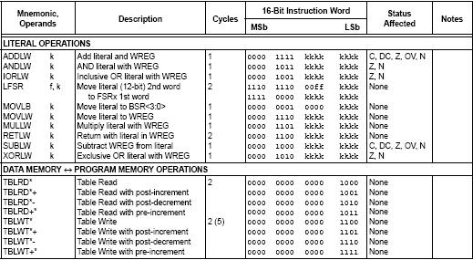
3 Theoretical Background: Microcontrollers are very important devices in the digital world, so it is necessary to know how to program them, and in order to do this you may use assembly language instructions for PIC18F452 device, and by referring to the device datasheet the following table (Table 1.1) illustrates those instructions. Table 1.1 Exp 1: PIC18F452 Assembly Instructions 2 of 4

4 Exp 1: PIC18F452 Assembly Instructions 3 of 4
5 Procedure: Write a program that adding the lower 4-bits of the input data at portc to the higher 4- bits and moving the result to portb register. Build the required circuit. Program the device and make sure the circuit is ready to turn the power on. Consult your Lab. Supervisor to turn the power on. Discussion and Analysis: Observe the execution of the code in the circuit and make your decision about your program if it matches the application requirements or not. Exp 1: PIC18F452 Assembly Instructions 4 of 4
6 The Hashemite University Faculty of Engineering Department of Mechatronics Engineering Microprocessors and Microcontrollers Lab. Experiment 2 Input and Output Ports This experiment focuses on dealing with Input and Output Ports for PIC18F452 device. Objectives: 1. To make the student familiar with the Input and Output Ports of PIC18F452 device. 2. To know the way of choosing the port to be input or output according to the application requirements Apparatus: The devices used in this experiment are: 1. Programmer 2. PIC18F452 IC 3. Breadboard and electronic components as shown in Figure 2.1 Figure 2.1: Equipment and devices used in the experiment. Exp 2: Input and Output Ports 1 of 3

7 Theoretical Background: PIC18F452 Microcontroller has five I/O ports (PortA, PortB, PortC, PortD, and PortE) that can be defined as input or output ports according to application. Referring to PIC18F452 datasheet at chapter 9: Exp 2: Input and Output Ports 2 of 3
8 Procedure: Write a program that increases the value at portb by 1 if the button at portc-0 was pressed, decreases portb value if the button at portc-1 was pressed and moving the portb data to portd if the button at portc-2 was pressed. Build the required circuit. Program the device and make sure the circuit is ready to turn the power on. Consult your Lab. Supervisor to turn the power on. Discussion and Analysis: Observe the execution of the code in the circuit and make your decision about your program if it matches the application requirements or not. Exp 2: Input and Output Ports 3 of 3
9 The Hashemite University Faculty of Engineering Department of Mechatronics Engineering Microprocessors and Microcontrollers Lab. Experiment 3 Wait Code Implementation This experiment focuses on implementing wait code using PIC18F452 device. Objectives: 1. To make the student familiar with the wait code implementation in PIC18F452 device. 2. To know how to change the wait time according to the application requirements. Apparatus: The devices used in this experiment are: 1. Programmer 2. PIC18F452 IC 3. Breadboard and electronic components as shown in Figure 3.1 Figure 3.1: Equipment and devices used in the experiment. Exp 3: Wait Code Implementation 1 of 3
10 Theoretical Background: One way of make delays between operations is to do a wait or delay code with the required time Example: WAIT: MOVLW D 1 MOVWF TIME3 NEXT3: MOVLW D'100' MOVWF TIME2 NEXT2: MOVLW D'199' MOVWF TIME1 NEXT1: NOP NOP DECFSZ TIME1,1 GOTO NEXT1 DECFSZ TIME2,1 GOTO NEXT2 DECFSZ TIME3,1 GOTO NEXT3 The delay time of the previous code can be calculated to give ms. Procedure: Write a code that increasing the data at portb by 1 and if the portb value was odd then it will wait for 1 second and if it is even it will wait 2 seconds to do the next increment. Build the required circuit. Program the device and make sure the circuit is ready to turn the power on. Consult your Lab. Supervisor to turn the power on. Exp 3: Wait Code Implementation 2 of 3
11 Discussion and Analysis: Observe the execution of the code in the circuit and make your decision about your program if it matches the application requirements or not. Exp 3: Wait Code Implementation 3 of 3
12 The Hashemite University Faculty of Engineering Department of Mechatronics Engineering Microprocessors and Microcontrollers Lab. Experiment 4 Analog to Digital Converter This experiment focuses on dealing with PIC18F452 device built in analog to digital converter. Objectives: 1. To make the student familiar with the PIC18F452 device A/D hardware. 2. To know how to change the different A/D settings to match the application requirements. Apparatus: The devices used in this experiment are: 1. Programmer 2. PIC18F452 IC 3. Breadboard and electronic components as shown in Figure 4.1 Figure 4.1: Equipment and devices used in the experiment. Exp 4: Analog to Digital Converter 1 of 3
13 Theoretical Background: A lot of sensors in the real are analog sensors that gives analog voltages, so it is important to know how to read the analog voltages using A/D hardware. Referring to PIC18F452 datasheet chapter 17: Exp 4: Analog to Digital Converter 2 of 3
14 Procedure: Write a code that makes a variable delay time between toggling the value of portb depending on the analog input at AN0 Program the device and make sure the circuit is ready to turn the power on. Consult your Lab. Supervisor to turn the power on. Discussion and Analysis: Observe the execution of the code in the circuit and make your decision about your program if it matches the application requirements or not. Exp 4: Analog to Digital Converter 3 of 3
15 The Hashemite University Faculty of Engineering Department of Mechatronics Engineering Microprocessors and Microcontrollers Lab. Experiment 5 Pulse Width Modulation This experiment focuses on dealing with PIC18F452 device built in Pulse Width Modulation hardware. Objectives: 1. To make the student familiar with the PIC18F452 device PWM hardware. 2. To know how to change the different PWM settings to match the application requirements. Apparatus: The devices used in this experiment are: 1. Programmer 2. PIC18F452 IC 3. Breadboard and electronic components as shown in Figure 5.1 Figure 5.1: Equipment and devices used in the experiment. Exp 5: Pulse Width Modulation 1 of 3
16 Theoretical Background: PWM is existed in a lot of applications that control some systems through changing the equivalent DC voltage, so it is important to deal with it in microcontrollers. Referring to PIC18F452 datasheet chapter 14 Exp 5: Pulse Width Modulation 2 of 3
17 Procedure: Write a program that changes the duty cycle of the output pulses of RC2 depending on the analog input at AN0. Program the device and make sure the circuit is ready to turn the power on. Consult your Lab. Supervisor to turn the power on. Discussion and Analysis: Observe the execution of the code in the circuit and make your decision about your program if it matches the application requirements or not. Exp 5: Pulse Width Modulation 3 of 3

18 The Hashemite University Faculty of Engineering Department of Mechatronics Engineering Microprocessors and Microcontrollers Lab. Experiment 6 External Interrupt This experiment focuses on dealing with PIC18F452 device built in External Interrupt handler. Objectives: 1. To make the student familiar with the PIC18F452 device Interrupt. 2. To know how to change the different Interrupt settings to match the application requirements. Apparatus: The devices used in this experiment are: 1. Programmer 2. PIC18F452 IC 3. Breadboard and electronic components as shown in Figure 6.1 Figure 6.1: Equipment and devices used in the experiment. Exp 6: External Interrupt 1 of 3
19 Theoretical Background: Interrupt is very important in microprocessors especially in event driven routines, so it can introduce different methods to deal with hardware. Referring to PIC18F452 datasheet chapter 8 Exp 6: External Interrupt 2 of 3
20 Procedure: Write a program that calculates the number of times the button at RB0 was pressed in 3 seconds time and displays it at portc. Program the device and make sure the circuit is ready to turn the power on. Consult your Lab. Supervisor to turn the power on. Discussion and Analysis: Observe the execution of the code in the circuit and make your decision about your program if it matches the application requirements or not. Exp 6: External Interrupt 3 of 3
ELCT 912: Advanced Embedded Systems
 ELCT 912: Advanced Embedded Systems Lecture 5: PIC Peripherals on Chip Dr. Mohamed Abd El Ghany, Department of Electronics and Electrical Engineering The PIC Family: Peripherals Different PICs have different
Laboratory Exercise 1 Microcontroller Board with Driver Board
 Laboratory Exercise 1 Microcontroller Board with Driver Board The purpose of this lab exercises is to demonstrate how the Microcontroller Board can be used to control motors connected to the Driver Board
Binary Outputs: LEDs
 Diode Theory Binary Outputs: LEDs A diode allows current to flow in only one direction. A diode consists of a semiconductor pn junction: In Silicon, the number of free electrons is a constant: np n i 2
' The PicBasic Pro Compiler Manual is on line at: '
 ---------------Title-------------- File...4331_encoder4.pbp Started...1/10/10 Microcontroller Used: Microchip Technology 18F4331 Available at: http://www.microchipdirect.com/productdetails.aspx?category=pic18f4331
Embedded Systems. Interfacing PIC with external devices Analog to digital Converter. Eng. Anis Nazer Second Semester
 Embedded Systems Interfacing PIC with external devices Analog to digital Converter Eng. Anis Nazer Second Semester 2016-2017 What is the time? What is the time? Definition Analog: can take any value Digital:
Pulse-Width-Modulation Motor Speed Control with a PIC (modified from lab text by Alciatore)
") Laboratory 14 Pulse-Width-Modulation Motor Speed Control with a PIC (modified from lab text by Alciatore) Required Components: 1x PIC 16F88 18P-DIP microcontroller 3x 0.1 F capacitors 1x 12-button numeric
Laboratory 14 Pulse-Width-Modulation Motor Speed Control with a PIC (modified from lab text by Alciatore) Required Components: 1x PIC 16F88 18P-DIP microcontroller 3x 0.1 F capacitors 1x 12-button numeric
;;;;;;; Variables ;;;;;;;;;;;;;;;;;;;;;;;;;;;;;;;;;;;;;;;;;;;;;;;;;;;;;;;;;;;;; cblock Bank0RAM ;Temporary storage for STATUS during interrupts
 TotPrgm2 Senior Design Program for Total Project (LED and Motor Control) Hayden Callender list P=PIC16F877, F=INHX8M, C=160, N=77, ST=OFF, MM=OFF, R=DEC, X=OFF #include P16F877.inc config(_cp_off & _PWRTE_ON
νµθωερτψυιοπασδφγηϕκλζξχϖβνµθωερτ ψυιοπασδφγηϕκλζξχϖβνµθωερτψυιοπα σδφγηϕκλζξχϖβνµθωερτψυιοπασδφγηϕκ χϖβνµθωερτψυιοπασδφγηϕκλζξχϖβνµθ
 θωερτψυιοπασδφγηϕκλζξχϖβνµθωερτψ υιοπασδφγηϕκλζξχϖβνµθωερτψυιοπασδ φγηϕκλζξχϖβνµθωερτψυιοπασδφγηϕκλζ ξχϖβνµθωερτψυιοπασδφγηϕκλζξχϖβνµ EE 331 Design Project Final Report θωερτψυιοπασδφγηϕκλζξχϖβνµθωερτψ
Simple Bridge Stand Alone H-Bridge Data Sheet Revision 1 August 2005
 Simple Bridge Stand Alone H-Bridge Revision August 00 SOLUTIONS CUBED, LLC East First Street Chico, CA 99 phone: 0.9.0 fax: 0.9. www.solutions-cubed.com Copyright 00, LLC Simple Bridge Page Table of Contents.0
PIC ADC to PWM and Mosfet Low-Side Driver
 Name Lab Section PIC ADC to PWM and Mosfet Low-Side Driver Lab 6 Introduction: In this lab you will convert an analog voltage into a pulse width modulation (PWM) duty cycle. The source of the analog voltage
EXERCISE 4: A Simple Hi-Fi
 EXERCISE 4: A Simple Hi-Fi EXERCISE OBJECTIVE When you have completed this exercise, you will be able to summarize the features of types of sensors that can be used with electronic control systems. You
Department of Mechanical and Industrial Engineering MECH 471 MICROCONTROLLERS FOR MECHATRONICS. Laboratory Specialist
 Department of Mechanical and Industrial Engineering MECH 471 laboratory manual 2011 MICROCONTROLLERS FOR MECHATRONICS Belal M. Ibrahim Laboratory Specialist General Safety Rules Electric and electronic
PIC Analog Voltage to PWM Duty Cycle
 Name Lab Section PIC Analog Voltage to PWM Duty Cycle Lab 5 Introduction: In this lab you will convert an analog voltage into a pulse width modulation (PWM) duty cycle. The source of the analog voltage
Laboratory 11. Pulse-Width-Modulation Motor Speed Control with a PIC
 Laboratory 11 Pulse-Width-Modulation Motor Speed Control with a PIC Required Components: 1 PIC16F88 18P-DIP microcontroller 3 0.1 F capacitors 1 12-button numeric keypad 1 NO pushbutton switch 1 Radio
More Fun with A/D Converters
 More Fun with A/D Converters The A/D input allows you to input numbers (0 to 1023) into the PIC processor with a potentiometer. This illustrates some of the things this allows you to do: Electronic Trombone:
MicroToys Guide: Motors N. Pinckney April 2005
 Introduction Three types of motors are applicable to small projects: DC brushed motors, stepper motors, and servo motors. DC brushed motors simply rotate in a direction dependent on the flow of current.
Hi Hsiao-Lung Chan Dept Electrical Engineering Chang Gung University, Taiwan
 Timers and CCP Modules Hi Hsiao-Lung Chan Dept Electrical Engineering Chang Gung University, Taiwan chanhl@mail.cgu.edu.twcgu PIC18 Timers Timer2, Timer4 8-bit timers use instruction cycle clock as the
Programming PIC Microcontrollers in PicBasic Pro LCD Lesson 3 Cornerstone Electronics Technology and Robotics II
 Programming PIC Microcontrollers in PicBasic Pro LCD Lesson 3 Cornerstone Electronics Technology and Robotics II Administration: o Prayer PicBasic Pro Programs Used in This Lesson: o General PicBasic Pro
Lesson 19 In-Circuit Programming
 Elmer 160 Lesson 19 Overview Lesson 19 Introduction When the designer makes a new circuit, there is often some time spent in developing the software for that circuit. Removing the PIC from the circuit
ESE 350 Microcontroller Laboratory Lab 5: Sensor-Actuator Lab
 ESE 350 Microcontroller Laboratory Lab 5: Sensor-Actuator Lab The purpose of this lab is to learn about sensors and use the ADC module to digitize the sensor signals. You will use the digitized signals
Physics 335 Lab 7 - Microcontroller PWM Waveform Generation
 Physics 335 Lab 7 - Microcontroller PWM Waveform Generation In the previous lab you learned how to setup the PWM module and create a pulse-width modulated digital signal with a specific period and duty
ECE Senior Design Final Report For. Scalable Regulated Three Phase Power Rectifier. May 10, 2004 Rev. 1.0
 ECE Senior Design Final Report For Scalable Regulated Three Phase Power Rectifier May 10, 2004 Rev. 1.0 Sponsors: Dr. Herb Hess (University of Idaho) Dr. Richard Wall (University of Idaho) Instructor:
Figure 1: One Possible Advanced Control System
 Control and Navigation 3 Cornerstone Electronics Technology and Robotics III (Notes primarily from Underwater Robotics Science Design and Fabrication, an excellent book for the design, fabrication, and
EE 109 Midterm Review
 EE 109 Midterm Review 1 2 Number Systems Computer use base 2 (binary) 0 and 1 Humans use base 10 (decimal) 0 to 9 Humans using computers: Base 16 (hexadecimal) 0 to 15 (0 to 9,A,B,C,D,E,F) Base 8 (octal)
LM4: The timer unit of the MC9S12DP256B/C
 Objectives - To explore the Enhanced Capture Timer unit (ECT) of the MC9S12DP256B/C - To program a real-time clock signal with a fixed period and display it using the onboard LEDs (flashing light) - To
LINE MAZE SOLVING ROBOT
 LINE MAZE SOLVING ROBOT EEE 456 REPORT OF INTRODUCTION TO ROBOTICS PORJECT PROJECT OWNER: HAKAN UÇAROĞLU 2000502055 INSTRUCTOR: AHMET ÖZKURT 1 CONTENTS I- Abstract II- Sensor Circuit III- Compare Circuit
Lab 5: Inverted Pendulum PID Control
 Lab 5: Inverted Pendulum PID Control In this lab we will be learning about PID (Proportional Integral Derivative) control and using it to keep an inverted pendulum system upright. We chose an inverted
Direct Current Waveforms
 Cornerstone Electronics Technology and Robotics I Week 20 DC and AC Administration: o Prayer o Turn in quiz Direct Current (dc): o Direct current moves in only one direction in a circuit. o Though dc must
Lecture #4 Outline. Announcements Project Proposal. AVR Processor Resources
 October 11, 2002 Stanford University - EE281 Lecture #4 #1 Announcements Project Proposal Lecture #4 Outline AVR Processor Resources A/D Converter (Analog to Digital) Analog Comparator Real-Time clock
MICROPROCESSORS A (17.383) Fall Lecture Outline
 Fall Lecture Outline") MICROPROCESSORS A (17.383) Fall 2010 Lecture Outline Class # 07 October 26, 2010 Dohn Bowden 1 Today s Lecture Syllabus review Microcontroller Hardware and/or Interface Finish Analog to Digital Conversion
MICROPROCESSORS A (17.383) Fall 2010 Lecture Outline Class # 07 October 26, 2010 Dohn Bowden 1 Today s Lecture Syllabus review Microcontroller Hardware and/or Interface Finish Analog to Digital Conversion
IST TSic Temperature Sensor IC Application Notes ZACwire Digital Output
 IST TSic Temperature Sensor IC ZACwire Digital Output CONTENTS 1 TSIC TM ZACWIRE TM COMMUNICATION PROTOCOL...2 1.1 TEMPERATURE TRANSMISSION PACKET FROM A TSIC TM...2 1.2 BIT ENCODING...3 1.3 HOW TO READ
International Journal of Advances in Science and Technology (IJAST)
") Signal detection and FFT calculation using ATmega644 microcontroller D. Sarkar 1, A.Chowdhury 2 1,2 Department of Electronics & Communication Engineering, NIT Agartala, India ABSTRACT: Detection of a signal
Signal detection and FFT calculation using ATmega644 microcontroller D. Sarkar 1, A.Chowdhury 2 1,2 Department of Electronics & Communication Engineering, NIT Agartala, India ABSTRACT: Detection of a signal
Implementation of Multiquadrant D.C. Drive Using Microcontroller
 Implementation of Multiquadrant D.C. Drive Using Microcontroller Author Seema Telang M.Tech. (IV Sem.) Department of Electrical Engineering Shri Ramdeobaba College of Engineering and Management Abstract
EE 314 Spring 2003 Microprocessor Systems
 EE 314 Spring 2003 Microprocessor Systems Laboratory Project #9 Closed Loop Control Overview and Introduction This project will bring together several pieces of software and draw on knowledge gained in
EASTERN MEDITERRANEAN UNIVERSITY FACULTY OF ENGINEERING Electrical and Electronics Engineering Department
 EASTERN MEDITERRANEAN UNIVERSITY FACULTY OF ENGINEERING Electrical and Electronics Engineering Department Fall 2003-2004 EEE 420 Project Report Ahmet Cem VARDAR 004245 Project Title: Heart Rate Monitor
UNIVERSITY OF VICTORIA FACULTY OF ENGINEERING. SENG 466 Software for Embedded and Mechatronic Systems. Project 1 Report. May 25, 2006.
 UNIVERSITY OF VICTORIA FACULTY OF ENGINEERING SENG 466 Software for Embedded and Mechatronic Systems Project 1 Report May 25, 2006 Group 3 Carl Spani Abe Friesen Lianne Cheng 03-24523 01-27747 01-28963
GRAPHICAL LCD BASED DIGITAL OSCILLOSCOPE
 International Journal of Advanced Research in Engineering ISSN: 2394-2819 Technology & Sciences April-2016 Volume 3, Issue-4 E Email: editor@ijarets.org www.ijarets.org GRAPHICAL LCD BASED DIGITAL OSCILLOSCOPE
ME 4447 / ME 6405 MICROPROCESSOR CONTROL OF MANUFACTURING SYSTEMS / INTRODUCTION TO MECHATRONICS
 ME 4447 / ME 6405 MICROPROCESSOR CONTROL OF MANUFACTURING SYSTEMS / INTRODUCTION TO MECHATRONICS Instructor: Professor I. Charles Ume Phone: 404-894-7411 Office: MARC Building, Room 453 Office Hours: Wednesday
Instrument Cluster Display. Grant Scott III Erin Lawler Mike Carlson
 Instrument Cluster Display Grant Scott III Erin Lawler Mike Carlson ECE 570 December 4 th, 2014 Presentation Outline Introduction and Motivation Features Temperature Sensing LCD Display Fahrenheit/Celsius
Devantech SRF04 Ultra-Sonic Ranger Finder Cornerstone Electronics Technology and Robotics II
 Devantech SRF04 Ultra-Sonic Ranger Finder Cornerstone Electronics Technology and Robotics II Administration: o Prayer PicBasic Pro Programs Used in This Lesson: o General PicBasic Pro Program Listing:
Robotic Navigation Distance Control Platform
 Robotic Navigation Distance Control Platform System Block Diagram Student: Scott Sendra Project Advisors: Dr. Schertz Dr. Malinowski Date: November 18, 2003 Objective The objective of the Robotic Navigation
Directions for Wiring and Using The GEARS II (2) Channel Combination Controllers
 Channel Combination Controllers") Directions for Wiring and Using The GEARS II (2) Channel Combination Controllers PWM Input Signal Cable for the Valve Controller Plugs into the RC Receiver or Microprocessor Signal line. White = PWM Input
Directions for Wiring and Using The GEARS II (2) Channel Combination Controllers PWM Input Signal Cable for the Valve Controller Plugs into the RC Receiver or Microprocessor Signal line. White = PWM Input
GCE A level 1145/01 ELECTRONICS ET5
 Surname Other Names Centre Number 2 Candidate Number GCE A level 1145/01 ELECTRONICS ET5 A.M. WEDNESDAY, 12 June 2013 1½ hours ADDITIONAL MATERIALS In addition to this examination paper, you will need
MICROCONTROLLER TUTORIAL II TIMERS
 MICROCONTROLLER TUTORIAL II TIMERS WHAT IS A TIMER? We use timers every day - the simplest one can be found on your wrist A simple clock will time the seconds, minutes and hours elapsed in a given day
Project Final Report: Directional Remote Control
 Project Final Report: by Luca Zappaterra xxxx@gwu.edu CS 297 Embedded Systems The George Washington University April 25, 2010 Project Abstract In the project, a prototype of TV remote control which reacts
Course Introduction. Content 20 pages 3 questions. Learning Time 30 minutes
 Purpose The intent of this course is to provide you with information about the main features of the S08 Timer/PWM (TPM) interface module and how to configure and use it in common applications. Objectives
Arduino STEAM Academy Arduino STEM Academy Art without Engineering is dreaming. Engineering without Art is calculating. - Steven K.
 Arduino STEAM Academy Arduino STEM Academy Art without Engineering is dreaming. Engineering without Art is calculating. - Steven K. Roberts Page 1 See Appendix A, for Licensing Attribution information
MICROPROCESSORS AND MICROCONTROLLER 1
 MICROPROCESSORS AND MICROCONTROLLER 1 Microprocessor Applications Data Acquisition System Data acquisition is the process of sampling signals that measure real world physical conditions ( such as temperature,
GCE A level 1145/01 ELECTRONICS ET5. P.M. THURSDAY, 31 May hours. Centre Number. Candidate Number. Surname. Other Names
 Surname Other Names Centre Number 0 Candidate Number GCE A level 1145/01 ELECTRONICS ET5 P.M. THURSDAY, 31 May 2012 1 1 2 hours For s use Question Maximum Mark Mark Awarded 1. 6 2. 9 3. 8 4. 6 1145 010001
EXPERIMENT 6: Advanced I/O Programming
 EXPERIMENT 6: Advanced I/O Programming Objectives: To familiarize students with DC Motor control and Stepper Motor Interfacing. To utilize MikroC and MPLAB for Input Output Interfacing and motor control.
Introduction to Using the PIC16F877 Justin Rice IMDL Spring 2002
 Introduction to Using the PIC16F877 Justin Rice IMDL Spring 2002 Basic Specs: - 30 pins capable of digital I/O - 8 that can be analog inputs - 2 capable of PWM - 8K of nonvolatile FLASH memory - 386 bytes
School of Engineering Mechatronics Engineering Department. Experim. ment no. 1
 University of Jordan School of Engineering Mechatronics Engineering Department 2010 Mechatronics System Design Lab Experim ment no. 1 PRINCIPLES OF SWITCHING Copyrights' are held by : Eng. Ala' Bata &
Final Project Report E3390 Electronic Circuits Design Lab. The Seeing Natcar
 Final Project Report E3390 Electronic Circuits Design Lab The Seeing Natcar Peter Fredrickson Federico Garcia Antonio Gellineau Steven Mon Submitted in partial fulfillment of the requirements for the Bachelor
Microcontroller: Timers, ADC
 Microcontroller: Timers, ADC Amarjeet Singh February 1, 2013 Logistics Please share the JTAG and USB cables for your assignment Lecture tomorrow by Nipun 2 Revision from last class When servicing an interrupt,
GCE A level 1145/01 ELECTRONICS ET5
 Surname Centre Number Candidate Number Other Names 2 GCE A level 1145/01 ELECTRONICS ET5 S16-1145-01 A.M. FRIDAY, 17 June 2016 1 hour 30 minutes For s use ADDITIONAL MATERIALS In addition to this examination
Mechatronics Project Kit - Getting Started Manual
 Mechatronics Project Kit - Getting Started Manual 40-100-1 Mechatronics Project Kit Getting Started Manual 40-100-1 Feedback Feedback Instruments Ltd, Park Road, Crowborough, E. Sussex, TN6 2QR, UK. Telephone:
Hardware Flags. and the RTI system. Microcomputer Architecture and Interfacing Colorado School of Mines Professor William Hoff
 Hardware Flags and the RTI system 1 Need for hardware flag Often a microcontroller needs to test whether some event has occurred, and then take an action For example A sensor outputs a pulse when a model
L13: (25%), (20%), (5%) ECTE333
, (20%), (5%) ECTE333") ECTE333 s schedule ECTE333 Lecture 1 - Pulse Width Modulator School of Electrical, Computer and Telecommunications Engineering University of Wollongong Australia Week Lecture (2h) Tutorial (1h) Lab (2h)
ECTE333 s schedule ECTE333 Lecture 1 - Pulse Width Modulator School of Electrical, Computer and Telecommunications Engineering University of Wollongong Australia Week Lecture (2h) Tutorial (1h) Lab (2h)
arxiv:physics/ v1 [physics.ed-ph] 19 Oct 2004
![arxiv:physics/ v1 [physics.ed-ph] 19 Oct 2004](/thumbs/75/71518783.jpg "arxiv:physics/ v1 [physics.ed-ph] 19 Oct 2004") I. SIMPLE 8085 µp COMPATIBLE I/O CARD with Arti Dwivedi Abstract A simple interfacing project with the 8085-microprocessor kits available in under graduate college labs has been discussed. The interface
I. SIMPLE 8085 µp COMPATIBLE I/O CARD with Arti Dwivedi Abstract A simple interfacing project with the 8085-microprocessor kits available in under graduate college labs has been discussed. The interface
PIC Functionality. General I/O Dedicated Interrupt Change State Interrupt Input Capture Output Compare PWM ADC RS232
 PIC Functionality General I/O Dedicated Interrupt Change State Interrupt Input Capture Output Compare PWM ADC RS232 General I/O Logic Output light LEDs Trigger solenoids Transfer data Logic Input Monitor
MICROPROCESSOR TECHNICS II
 AGH University of Science and Technology Faculty of Computer Science, Electronics and Telecommunication Department of Electronics MICROPROCESSOR TECHNICS II Tutorial 5 Combining ADC & PWM Mariusz Sokołowski
An Embedded Approach for Motor Control Boards Design in Mobile Robotics Applications
 An Embedded Approach for Motor Control Boards Design in Mobile Robotics Applications CLAUDIA MASSACCI, ANDREA USAI, PAOLO DI GIAMBERARDINO Department of Computer and System Sciences Antonio Ruberti University
Training Schedule. Robotic System Design using Arduino Platform
 Training Schedule Robotic System Design using Arduino Platform Session - 1 Embedded System Design Basics : Scope : To introduce Embedded Systems hardware design fundamentals to students. Processor Selection
Microcontrollers and Interfacing
 Microcontrollers and Interfacing Week 07 digital input, debouncing, interrupts and concurrency College of Information Science and Engineering Ritsumeikan University 1 this week digital input push-button
RC Filters and Basic Timer Functionality
 RC-1 Learning Objectives: RC Filters and Basic Timer Functionality The student who successfully completes this lab will be able to: Build circuits using passive components (resistors and capacitors) from
ECE 511: FINAL PROJECT REPORT GROUP 7 MSP430 TANK
 ECE 511: FINAL PROJECT REPORT GROUP 7 MSP430 TANK Team Members: Andrew Blanford Matthew Drummond Krishnaveni Das Dheeraj Reddy 1 Abstract: The goal of the project was to build an interactive and mobile
EE 308 Spring 2006 FINAL PROJECT: INTERFACING AND MOTOR CONTROL WEEK 1 PORT EXPANSION FOR THE MC9S12
 FINAL PROJECT: INTERFACING AND MOTOR CONTROL In this sequence of labs you will learn how to interface with additional hardware and implement a motor speed control system. WEEK 1 PORT EXPANSION FOR THE
Design and Simulation of Automatic Temperature Control and Alert System Based PIC16F887
 International Journal of Informatics and Communication Technology (IJ-ICT) Vol. 6, No. 2, August 2017, pp. 95~104 ISSN: 2252-8776, DOI: 10.11591/ijict.v6i2.pp95-104 95 Design and Simulation of Automatic
K7QO Marker Generator
 K7QO Marker Generator The history of marker generators begins with the commercial receivers of the early beginnings of electronics. Typical short wave receivers came with two dials, one labeled tuning
CprE 288 Introduction to Embedded Systems (Output Compare and PWM) Instructors: Dr. Phillip Jones
 Instructors: Dr. Phillip Jones") CprE 288 Introduction to Embedded Systems (Output Compare and PWM) Instructors: Dr. Phillip Jones 1 Announcements HW8: Due Sunday 10/29 (midnight) Exam 2: In class Thursday 11/9 This object detection lab
CprE 288 Introduction to Embedded Systems (Output Compare and PWM) Instructors: Dr. Phillip Jones 1 Announcements HW8: Due Sunday 10/29 (midnight) Exam 2: In class Thursday 11/9 This object detection lab
EE 308 Spring S12 SUBSYSTEMS: PULSE WIDTH MODULATION, A/D CONVERTER, AND SYNCHRONOUS SERIAN INTERFACE
 9S12 SUBSYSTEMS: PULSE WIDTH MODULATION, A/D CONVERTER, AND SYNCHRONOUS SERIAN INTERFACE In this sequence of three labs you will learn to use the 9S12 S hardware sybsystem. WEEK 1 PULSE WIDTH MODULATION
PICmicro MCU APPLICATION DESIGN AND HARDWARE INTERFACING
 6 PICmicro MCU APPLICATION DESIGN AND HARDWARE INTERFACING CONTENTS AT A GLANCE Estimating Application Power Requirements Reset Interfacing to External Devices DIGITAL LOGIC DIFFERENT LOGIC LEVELS WITH
Pulse Generation. Pulsout. 555 Timer. Software version of pulse generation Pulsout pin, Period
 Lecture 9 Pulse Generation Pulsout Software version of pulse generation Pulsout pin, Period Pin: specified I/O pin from 0 to 15 Period: 2 µsec per each unit 555 Timer Hardware version of pulse generation
ANGULAR POSITION CONTROL OF DC MOTOR USING SHORTEST PATH ALGORITHM
 EE 712 Embedded Systems Design, Lab Project Report, EE Dept. IIT Bombay, April 2006. ANGULAR POSITION CONTROL OF DC MOTOR USING SHORTEST PATH ALGORITHM Group Number: 17 Rupesh Sonu Kakade (05323014)
Arduino Microcontroller Processing for Everyone!: Third Edition / Steven F. Barrett
 Arduino Microcontroller Processing for Everyone!: Third Edition / Steven F. Barrett Anatomy of a Program Programs written for a microcontroller have a fairly repeatable format. Slight variations exist
Sensor Interface Using PIC12CXXX as a Sensor Interface for Metal Detection
 Using PIC12CXXX as a Sensor Interface for Metal Detection Author: Vladimir Velchev AVEX - Vladimir Velchev Sofia, Bulgaria email:avex@iname.com APPLICATION OPERATION PIC12CXXX microcontroller can be used
2015 Technological Studies. Advanced Higher. Finalised Marking Instructions
 05 Technological Studies Advanced Higher Finalised Marking Instructions Scottish Qualifications Authority 05 The information in this publication may be reproduced to support SQA qualifications only on
Chapter 6 PROGRAMMING THE TIMERS
 Chapter 6 PROGRAMMING THE TIMERS Force Outputs on Outcompare Input Captures Programmabl e Prescaling Prescaling Internal clock inputs Timer-counter Device Free Running Outcompares Lesson 2 Free Running
Monitoring Temperature using LM35 and Arduino UNO
 Sharif University of Technology Microprocessor Arduino UNO Project Monitoring Temperature using LM35 and Arduino UNO Authors: Sadegh Saberian 92106226 Armin Vakil 92110419 Ainaz Hajimoradlou 92106142 Supervisor:
Embedded Systems and Software
 Embedded Systems and Software Notes on Lab 2 Embedded Systems in Vehicles Lecture 2-4, Slide 1 Lab 02 In this lab students implement an interval timer using a pushbutton switch, ATtiny45, an LED driver,
Castle Creations, INC.
 Castle Link Live Communication Protocol Castle Creations, INC. 6-Feb-2012 Version 2.0 Subject to change at any time without notice or warning. Castle Link Live Communication Protocol - Page 1 1) Standard
Undefined Obstacle Avoidance and Path Planning
 Paper ID #6116 Undefined Obstacle Avoidance and Path Planning Prof. Akram Hossain, Purdue University, Calumet (Tech) Akram Hossain is a professor in the department of Engineering Technology and director
Hello, and welcome to this presentation of the STM32L4 comparators. It covers the main features of the ultra-lowpower comparators and some
 Hello, and welcome to this presentation of the STM32L4 comparators. It covers the main features of the ultra-lowpower comparators and some application examples. 1 The two comparators inside STM32 microcontroller
FABO ACADEMY X ELECTRONIC DESIGN
 ELECTRONIC DESIGN MAKE A DEVICE WITH INPUT & OUTPUT The Shanghaino can be programmed to use many input and output devices (a motor, a light sensor, etc) uploading an instruction code (a program) to it
Follow this and additional works at: Part of the Engineering Commons
 Trinity University Digital Commons @ Trinity Mechatronics Final Projects Engineering Science Department 5-2018 Pyramid of Disco Daniel Henkes Trinity University, dhenkes@trinity.edu Molly McCullough Trinity
' Turn off A/D converters (thereby allowing use of pins for I/O) ANSEL = 0
 ANSEL = 0") dc_motor.bas (PIC16F88 microcontroller) Design Example Position and Speed Control of a dc Servo Motor. The user interface includes a keypad for data entry and an LCD for text messages. The main menu offers
dc_motor.bas (PIC16F88 microcontroller) Design Example Position and Speed Control of a dc Servo Motor. The user interface includes a keypad for data entry and an LCD for text messages. The main menu offers
Interfacing to Analog World Sensor Interfacing
 Interfacing to Analog World Sensor Interfacing Introduction to Analog to digital Conversion Why Analog to Digital? Basics of A/D Conversion. A/D converter inside PIC16F887 Related Problems Prepared By-
Pulse Width Modulation
 ECEn 621" Computer Arithmetic" Project Notes Week 1 Pulse Width Modulation 1 Pulse Width Modulation A method of regulating the amount of voltage delivered to a load. The average value of the voltage fed
Graphical Control Panel User Manual
 Graphical Control Panel User Manual DS-MPE-DAQ0804 PCIe Minicard Data Acquisition Module For Universal Driver Version 7.0.0 and later Revision A.0 March 2015 Revision Date Comment A.0 3/18/2015 Initial
PERIPHERAL INTERFACING Rev. 1.0
 This work is licensed under the Creative Commons Attribution-NonCommercial-Share Alike 2.5 India License. To view a copy of this license, visit http://creativecommons.org/licenses/by-nc-sa/2.5/in/deed.en
Grundlagen Microcontroller Counter/Timer. Günther Gridling Bettina Weiss
 Grundlagen Microcontroller Counter/Timer Günther Gridling Bettina Weiss 1 Counter/Timer Lecture Overview Counter Timer Prescaler Input Capture Output Compare PWM 2 important feature of microcontroller
Lock Cracker S. Lust, E. Skjel, R. LeBlanc, C. Kim
 Lock Cracker S. Lust, E. Skjel, R. LeBlanc, C. Kim Abstract - This project utilized Eleven Engineering s XInC2 development board to control several peripheral devices to open a standard 40 digit combination
ME 461 Laboratory #2 Timers and Pulse-Width Modulation
 ME 461 Laboratory #2 Timers and Pulse-Width Modulation Goals: 1. Understand how to use timers to control the frequency at which events occur. 2. Generate PWM signals using Timer A. 3. Explore the frequency
IST TSic Temperature Sensor IC. Technical Notes ZACwire Digital Output
 IST TSic Temperature Sensor IC Technical Notes ZACwire Digital Output CONTENTS 1 ZACWIRE COMMUNICATION PROTOCOL FOR THE TSIC...2 1.1 TEMPERATURE TRANSMISSION PACKET FROM A TSIC TM...2 1.2 BIT ENCODING...3
FM Tuner Controller for Portable and Car Radios
 WIRELESS AND REMOTE CONTROLLED PERSONAL APPLIANCE FM Tuner Controller for Portable and Car Radios Author: T. K. Mani Model Engineering College Cochin, India email: ihrdmec@md2.vsnl.net.in APPLICATION OPERATION
Microcontroller Based Inductance Capacitance Meter
 Microcontroller Based Inductance Capacitance Meter MUDIT AGARWAL This is the Inductance / Capacitance Meters circuit. One can easily build this LC Meter measure inductances starting from mh to 00mH, µh
Embedded Systems. Oscillator and I/O Hardware. Eng. Anis Nazer First Semester
 Embedded Systems Oscillator and I/O Hardware Eng. Anis Nazer First Semester 2016-2017 Oscillator configurations Three possible configurations for Oscillator (a) using a crystal oscillator (b) using an
A NEW DECISION ALGORITHM FOR AUDIO VOTING SYSTEM
 IAENG International Journal of Computer Science, 32:4, IJCS_32_4_3 A NEW DECISION ALGORITHM FOR AUDIO VOTING SYSTEM M. Carbajo, M.D. R-Moreno, A. Moreno and J. de Pedro Departamento de Automática. Universidad
Timing System. Timing & PWM System. Timing System components. Usage of Timing System
 Timing & PWM System Timing System Valvano s chapter 6 TIM Block User Guide, Chapter 15 PWM Block User Guide, Chapter 12 1 2 Timing System components Usage of Timing System 3 Counting mechanisms Input time
CHAPTER 4 CONTROL ALGORITHM FOR PROPOSED H-BRIDGE MULTILEVEL INVERTER
 65 CHAPTER 4 CONTROL ALGORITHM FOR PROPOSED H-BRIDGE MULTILEVEL INVERTER 4.1 INTRODUCTION Many control strategies are available for the control of IMs. The Direct Torque Control (DTC) is one of the most