Programming PIC Microcontrollers in PicBasic Pro LCD Lesson 3 Cornerstone Electronics Technology and Robotics II
|
|
|
- Jacob Garrett
- 6 years ago
- Views:
Transcription
1 Programming PIC Microcontrollers in PicBasic Pro LCD Lesson 3 Cornerstone Electronics Technology and Robotics II Administration: o Prayer PicBasic Pro Programs Used in This Lesson: o General PicBasic Pro Program Listing: o Lab 1 lcd3 as.pdf file: o Lab 4 lcd1 as.pdf file: LCD PicBasic Programming: o New PICBasic Command: POT: Format POT Pin,Scale,Var Reads a resistive component (5K to 50K) such as a potentiometer on Pin. Pin may be called in the usual format, PORTB.0, or as a constant, 0 15, 0 is PORTB.0 and 15 is PORTA.7 (See section 4.11 Pins in the green PBP Compiler manual). To set Scale, see the POT command in the green microengineering Labs PicBasic Pro Compiler manual or the explanation and table below. Explanation of Scale: o Scale must be set empirically (with observation and experiments) such that the LCD readout value is 0 with the potentiometer set to one end and 255 when set to the other end. See the illustrations below. Scale Set Too High Scale Set Too Low Scale Set Properly Figure 1, POT Scale Settings Approximate Scale Values for Resistor R3 Resistor R3 in Schematic Below Approximate Scale Value 5K K 91 25K 45 50K 38 1
2 Example: POT 0,178,x POT reading on Pin RBO assigned to variable, x. Scale = 178 to give a full range of values over the potentiometer (0 to 255) for the variable, x. LCD Command Table Command $FE, 1 $FE, 2 $FE, $0C $FE, $0E $FE, $0F $FE, $10 $FE, $14 $FE, $18 $FE, $1C $FE, $80 $FE, $C0 $FE, $94 $FE, $D4 Operation Clear display Return home Cursor off Underline cursor on Blinking cursor on Move cursor left one position Move cursor right one position Display shift left Display shift right Move cursor to beginning of first line Move cursor to beginning of second line Move cursor to beginning of third line Move cursor to beginning of fourth line o Perform LCD3 LAB 1 lcd3.pbp o Perform LCD3 LAB K Series Resistors o Perform LCD3 LAB 3 LED Status on LCD Defining LCD Pins: o PicBasic Pro permits changing of LCD pin connections by using DEFINE statements. The LCD default pin connections are shown in Figure 2: Figure 2, LCD Default Connections 2
3 o To move the data connections, use the following DEFINE statements: DEFINE LCD_DREG sets the LCD data port. o DEFINE LCD_DREG PORTA Sets PORTA as LCD data port o DEFINE LCD_DREG PORTB Sets PORTB as LCD data port If an 8-bit data bus is used, all 8 bits must be in one port If a 4-bit data bus is used, the top 4 LCD data bits (DB4-DB7) must be either wired to the bottom 4 or top 4 bits of the port selected. For example, if DEFINE LCD_DREG PORTB is declared, then the top LCD bits DB4-DB7 must be connected to either RB0-RB3 or RB4- RB7 (see DEFINE LCD_DBIT immediately below). PicBasic Pro assumes the data lines DB4-DB7 are connected to PORTA.0-PORTA.3 (RA0-RA3). DEFINE LCD_DBIT sets starting data bit for 4-bit bus. o DEFINE LCD_DBIT 0 Set starting data bit to 0 o DEFINE LCD_DBIT 4 Set starting data bit to 4 PicBasic Pro default starting bit is bit 0 of PORTA or PORTA.0 Example: Move the data port AN0-AN3 to PORTB and the starting data bit to bit 4. Let Register Select and Enable connections remain unchanged. DEFINE Statements: o DEFINE LCD_DREG PORTB Sets PORTB as LCD data port o DEFINE LCD_DBIT 4 Set starting data bit to 4 The schematic in Figure 3 shows relocated the data port connections: Figure 3, Revised Data Port Connections 3
4 o To move the Register Select and Enable connections, use the following DEFINE statements: DEFINE LCD_RSREG sets the Register Select (RS) port. o DEFINE LCD_RSREG PORTB Sets PORTB as the RS port o DEFINE LCD_RSREG PORTE Sets PORTE as the RS port Register Select may be connected to any port pin. PicBasic Pro default setting for Register Select is PORTA. DEFINE LCD_RSBIT sets the Register Select (RS) bit. o DEFINE LCD_RSBIT 2 Sets bit 2 as RS bit o DEFINE LCD_RSBIT 6 Sets bit 6 as RS bit Register Select may be connected to any port pin. PicBasic Pro default setting for Register Select is bit 4 of PORTA or PORTA.4. DEFINE LCD_EREG sets the Enable (E) port. o DEFINE LCD_EREG PORTB Sets PORTB as Enable port o DEFINE LCD_EREG PORTD Sets PORTD as Enable port Enable may be connected to any port pin. PicBasic Pro default setting for Enable is PORTB. DEFINE LCD_EBIT sets the Enable (E) bit. o DEFINE LCD_EBIT 3 Sets bit 3 as the Enable bit o DEFINE LCD_EBIT 7 Sets bit 7 as the Enable bit Enable may be connected to any port pin. PicBasic Pro default setting for Enable is bit 3 of PORTB or PORTB.3. Example: Move the Register Select from AN4 to RB0 and the Enable from RB3 to RB1. Leave the data port connections in their default configuration. DEFINE Register Select Statements: o DEFINE LCD_RSREG PORTB Sets PORTB as the RS port o DEFINE LCD_RSBIT 0 Sets bit 0 as RS bit DEFINE Enable Statements: o DEFINE LCD_EREG PORTB Sets PORTB as Enable port o DEFINE LCD_EBIT 1 Sets bit 1 as the Enable bit The schematic in Figure 4 on the next page shows the relocated Register Select and Enable connections: 4
5 Figure 4, Revised Register Select and Enable Connections DEFINE LCD_BITS sets the bus size (4-bits or 8-bits). o DEFINE LCD_BITS 4 Sets 4-bit bus o DEFINE LCD_BITS 8 Sets 8-bit bus PicBasic Pro default setting for bus size is a 4-bit bus. DEFINE LCD_LINES sets the number of lines on the LCD. o DEFINE LCD_LINES 4 Sets LCD to display 4 lines o DEFINE LCD_LINES 2 Sets LCD to display 2 lines PicBasic Pro default setting is for the number of lines on the LCD is a 2 line LCD display. o In summary, LCD connections to PICs can be changed from their PIC default settings by using the DEFINE statements listed above. o We will need use these features in our lesson on analog-to-digital conversion. o Perform LCD3 LAB 4 Changing LCD Pins on a PIC 5
6 Cornerstone Electronics Technology and Robotics II LCD Lesson 3 LAB 1 lcd3.pbp Purpose: The purpose of this lab is to acquaint the student the PicBasic Pro command POT and the use of an LCD to monitor variable input values. Apparatus and Materials: 1 Analog/Digital Trainer PIC 16F88 Microcontroller Hantronix HDM16216H-5-300S 16x2 LCD, Jameco # K Potentiometer 10K Potentiometer (R3) 4.7 K Resistor 0.1 uf Capacitor Procedure: o Wire the in-circuit serial programming connections before proceeding. See Lesson 15A, In-Circuit Serial Programming for details. o Now add the following circuitry. Use a 10K trimpot for R3: o Open lcd3.pbp and download into the PIC16F88. Adjust the 10K potentiometer R3 to see if the full range of the potentiometer is engaged. If the full range is not active, adjust the Scale value in the POT command to make the full range active. Do this by empirically (through observation and experimentation) setting the Scale value to its lowest number while the LCD displays
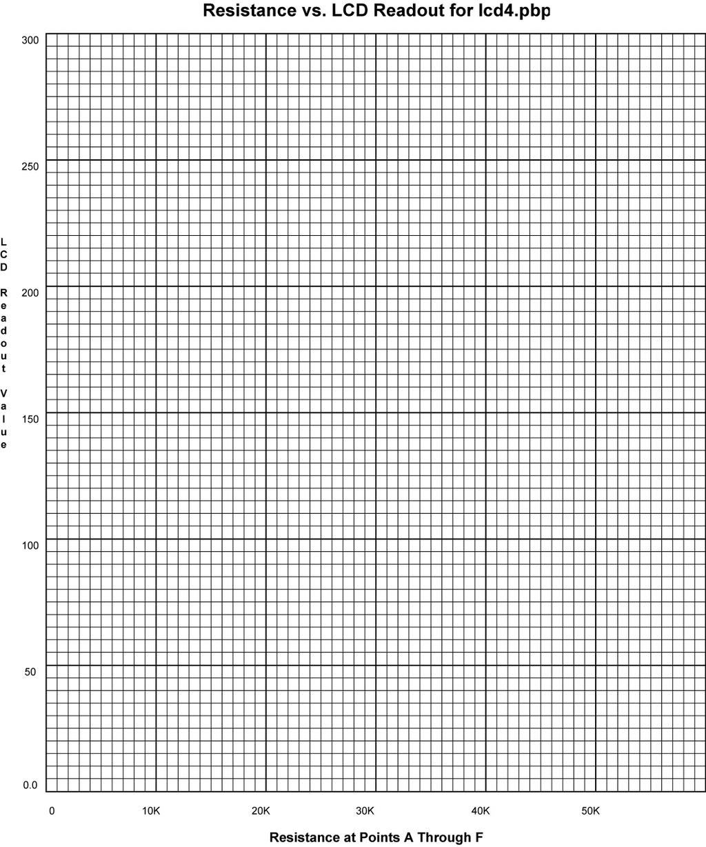
7 Cornerstone Electronics Technology and Robotics II LCD Lesson 3 LAB 2 Five 10K Series Resistors Purpose: The purpose of this lab is to acquaint the student the fact that the PicBasic Pro command POT in non-linear in nature. Apparatus and Materials: 1 Analog/Digital Trainer PIC 16F88 Microcontroller Hantronix HDM16216H-5-300S 16x2 LCD, Jameco # K Potentiometer 5-10K Resistors 4.7 K Resistor 0.1 uf Capacitor Procedure: o Wire the circuit LCD4 below and program the chip with lcd3.pbp. o Connect pin RB1 to Point A as shown in the schematic below. Set the POT command Scale value such that the 255 is the full range for the 5 10K resistors. Start by setting the Scale low so the LCD reads a number below 255, and then raise the Scale until you reach a full range reading of 255. o Now connect RB1 to Points B through F and plot the results on the accompanying graph. Observe the non-linear nature of the plot. 7
8 8
9 Cornerstone Electronics Technology and Robotics II LCD Lesson 3 LAB 3 LED Status on LCD Purpose: The purpose of this lab is to acquaint the student with using an LCD to display the state of an output. Apparatus and Materials: Analog/Digital Trainer or Breadboard w/ 5VDC Supply PIC 16F88 Microcontroller Hantronix HDM16216H-5-300S 16x2 LCD, Jameco # K Resistor Ohm Resistors 20 K Potentiometer 2 LEDs Procedure: o Wire the following circuit lcd1. o Open blink1.pbp from your folder and run the program. Challenges: o Connect one LED (LED1) with a 150 ohm resistor to PORTB.1 and program it to blink on and off every second. Display LED1 and its state (0 or 1) as a variable on the LCD. Save the program as lcd16.pbp. Don t forget to set the proper bits in the TRISB register to outputs as needed. o Connect a second LED (LED2) to PORTB.2 and program it to blink opposite LED1. Display LED1 on the first line and LED2 on the second line with their respective states as variables. Save the program as lcd17.pbp. 9
10 Cornerstone Electronics Technology and Robotics II LCD Lesson 3 LAB 4 Changing LCD Pins on a PIC Purpose: The purpose of this lab is to acquaint the student with changing the default connections of an LCD to a PIC chip. Apparatus and Materials: Analog/Digital Trainer or Breadboard w/ 5VDC Supply PIC 16F88 Microcontroller Hantronix HDM16216H-5-300S 16x2 LCD, Jameco # K Resistor 1 20 K Potentiometer Procedure: o Wire the following circuit lcd1. o Download lcd1.pbp into the PIC16F88 o Change the LCD pin connections from their default settings to: Data port: PORTB Starting data bit: 0 Register Select port: PORTB Register Select bit: 4 Enable port: PORTB Enable bit: 5 4 or 8-bit bus: 4-bit bus, the PBP default setting Lines on LCD: 2, the PBP default setting o Save the revised lcd1.pbp as lcd18.pbp o Rewire the circuit to reflect the change in LCD pin connections. 10
' The PicBasic Pro Compiler Manual is on line at: '
 ---------------Title-------------- File...4331_encoder4.pbp Started...1/10/10 Microcontroller Used: Microchip Technology 18F4331 Available at: http://www.microchipdirect.com/productdetails.aspx?category=pic18f4331
o What happens if S1 and S2 or S3 and S4 are closed simultaneously? o Perform Motor Control, H-Bridges LAB 2 H-Bridges with SPST Switches
 Cornerstone Electronics Technology and Robotics II H-Bridges and Electronic Motor Control 4 Hour Class Administration: o Prayer o Debriefing Botball competition Four States of a DC Motor with Terminals
Devantech SRF04 Ultra-Sonic Ranger Finder Cornerstone Electronics Technology and Robotics II
 Devantech SRF04 Ultra-Sonic Ranger Finder Cornerstone Electronics Technology and Robotics II Administration: o Prayer PicBasic Pro Programs Used in This Lesson: o General PicBasic Pro Program Listing:
Laboratory 11. Pulse-Width-Modulation Motor Speed Control with a PIC
 Laboratory 11 Pulse-Width-Modulation Motor Speed Control with a PIC Required Components: 1 PIC16F88 18P-DIP microcontroller 3 0.1 F capacitors 1 12-button numeric keypad 1 NO pushbutton switch 1 Radio
Direct Current Waveforms
 Cornerstone Electronics Technology and Robotics I Week 20 DC and AC Administration: o Prayer o Turn in quiz Direct Current (dc): o Direct current moves in only one direction in a circuit. o Though dc must
Electronics Review 1 Cornerstone Electronics Technology and Robotics II Week 1
 Electronics Review 1 Cornerstone Electronics Technology and Robotics II Week 1 Administration: o Prayer o Welcome back o Review Quiz 1 Review: o Reading meters: When a current or voltage value is unknown,
Hashemite University Faculty of Engineering Mechatronics Engineering Department. Microprocessors and Microcontrollers Laboratory
 Hashemite University Faculty of Engineering Mechatronics Engineering Department Microprocessors and Microcontrollers Laboratory The Hashemite University Faculty of Engineering Department of Mechatronics
Figure 1: Basic Relationships for a Comparator. For example: Figure 2: Example of Basic Relationships for a Comparator
 Cornerstone Electronics Technology and Robotics I Week 16 Voltage Comparators Administration: o Prayer Robot Building for Beginners, Chapter 15, Voltage Comparators: o Review of Sandwich s Circuit: To
Figure 1: One Possible Advanced Control System
 Control and Navigation 3 Cornerstone Electronics Technology and Robotics III (Notes primarily from Underwater Robotics Science Design and Fabrication, an excellent book for the design, fabrication, and
Pulse-Width-Modulation Motor Speed Control with a PIC (modified from lab text by Alciatore)
") Laboratory 14 Pulse-Width-Modulation Motor Speed Control with a PIC (modified from lab text by Alciatore) Required Components: 1x PIC 16F88 18P-DIP microcontroller 3x 0.1 F capacitors 1x 12-button numeric
Laboratory 14 Pulse-Width-Modulation Motor Speed Control with a PIC (modified from lab text by Alciatore) Required Components: 1x PIC 16F88 18P-DIP microcontroller 3x 0.1 F capacitors 1x 12-button numeric
t w = Continue to the next page, where you will draw a diagram of your design.
 Name EET 1131 Lab #13 Multivibrators OBJECTIVES: 1. To design and test a monostable multivibrator (one-shot) using a 555 IC. 2. To analyze and test an astable multivibrator (oscillator) using a 555 IC.
infraled Zeppelin Nick Wagner, Austin Jurgensmeyer, and Christopher Record 12/16/08
 infraled Zeppelin Nick Wagner, Austin Jurgensmeyer, and Christopher Record //08 The infraled Zeppelin is a blimp capable of autonomous and remote control flight. In either mode, the blimp uses the pulse
GF of 9 THE GADGET FREAK FILES CASE #165. Analog Clock Measures Time in Meters
 GF 165 04-05-2010 1 of 9 THE GADGET FREAK FILES CASE #165 Analog Clock Measures Time in Meters Alan Parekh took a different approach to time keeping with his electronic clock that registers hours, minutes,
Lab 3 Final report: Embedded Systems Digital Potentiometer Subsystem TEAM: RAR
 Lab 3 Final report: Embedded Systems Digital Potentiometer Subsystem TEAM: RAR EE 300W, Section 6 Professor Tim Wheeler Rui Xia, Yuanpeng Liao and Ashwin Ramnarayanan Table of Contents Introduction...2
Potentiometer Tutorial Cornerstone Electronics Technology and Robotics I Week 8
 Potentiometer Tutorial Cornerstone Electronics Technology and Robotics I Week 8 Electricity and Electronics, Section 3.5, Potentiometers: o Potentiometers: A potentiometer is a type of variable resistor
ECE Senior Design Final Report For. Scalable Regulated Three Phase Power Rectifier. May 10, 2004 Rev. 1.0
 ECE Senior Design Final Report For Scalable Regulated Three Phase Power Rectifier May 10, 2004 Rev. 1.0 Sponsors: Dr. Herb Hess (University of Idaho) Dr. Richard Wall (University of Idaho) Instructor:
Operational Amplifiers 2 Active Filters ReadMeFirst
 Operational Amplifiers 2 Active Filters ReadMeFirst Lab Summary In this lab you will build two active filters on a breadboard, using an op-amp, resistors, and capacitors, and take data for the magnitude
o Semiconductor Diode Symbol: The cathode contains the N-type material and the anode contains the P-type material.
 Cornerstone Electronics Technology and Robotics I Week 16 Diodes and Transistor Switches Administration: o Prayer o Turn in quiz Review: o Design and wire a voltage divider that divides your +9 V voltage
Introduction to Using the PIC16F877 Justin Rice IMDL Spring 2002
 Introduction to Using the PIC16F877 Justin Rice IMDL Spring 2002 Basic Specs: - 30 pins capable of digital I/O - 8 that can be analog inputs - 2 capable of PWM - 8K of nonvolatile FLASH memory - 386 bytes
Digital-to-Analog Converter. Lab 3 Final Report
 Digital-to-Analog Converter Lab 3 Final Report The Ion Cannons: Shrinand Aggarwal Cameron Francis Nicholas Polito Section 2 May 1, 2017 1 Table of Contents Introduction..3 Rationale..3 Theory of Operation.3
Automated flight through inertial navigation and digital fly-by-wire systems
 University of Arkansas, Fayetteville ScholarWorks@UARK Mechanical Engineering Undergraduate Honors Theses Mechanical Engineering 5-2009 Automated flight through inertial navigation and digital fly-by-wire
Microprocessors A Lab 4 Fall Analog to Digital Conversion Using the PIC16F684 Microcontroller
 Objectives Materials 17.383 Microprocessors A Analog to Digital Conversion Using the PIC16F684 Microcontroller 1) To use MPLAB IDE software, PICC Compiler, and external hardware to demonstrate the following:
EE-110 Introduction to Engineering & Laboratory Experience Saeid Rahimi, Ph.D. Labs Introduction to Arduino
 EE-110 Introduction to Engineering & Laboratory Experience Saeid Rahimi, Ph.D. Labs 10-11 Introduction to Arduino In this lab we will introduce the idea of using a microcontroller as a tool for controlling
PART 1: DESCRIPTION OF THE DIGITAL CONTROL SYSTEM
 ELECTRICAL ENGINEERING TECHNOLOGY PROGRAM EET 433 CONTROL SYSTEMS ANALYSIS AND DESIGN LABORATORY EXPERIENCES INTRODUCTION TO DIGITAL CONTROL PART 1: DESCRIPTION OF THE DIGITAL CONTROL SYSTEM 1. INTRODUCTION
Cornerstone Electronics Technology and Robotics I Week 19 Electrical Relays
 Cornerstone Electronics Technology and Robotics I Week 19 Electrical Relays Administration: o Prayer o Turn in quiz o Review voltage regulators: Review SPST, SPDT, DPST, DPDT switches http://cornerstonerobotics.org/curriculum/lessons_year1/er%20week8,%
Circuit LED 1 LED 2 A on or off on or off B on or off on or off C on or off on or off
 Cornerstone Electronics Technology and Robotics Week 8 Chapter 3, Introduction to Basic Electrical Circuit Materials Continued Administration: o Prayer o Turn in quiz Review LED s: o Wire the following
Exercise 1: The Rheostat
 Potentiometers and Rheostats DC Fundamentals Exercise 1: The Rheostat EXERCISE OBJECTIVE When you have completed this exercise, you will be able to vary current by using a rheostat. You will verify your
EXERCISE 4: A Simple Hi-Fi
 EXERCISE 4: A Simple Hi-Fi EXERCISE OBJECTIVE When you have completed this exercise, you will be able to summarize the features of types of sensors that can be used with electronic control systems. You
Follow this and additional works at: Part of the Engineering Commons
 Trinity University Digital Commons @ Trinity Mechatronics Final Projects Engineering Science Department 5-2018 Pyramid of Disco Daniel Henkes Trinity University, dhenkes@trinity.edu Molly McCullough Trinity
Laboration: AD-conversion and the Thevenin theorem.
 Laboration: AD-conversion and the Thevenin theorem. Embedded Electronics IE1206 Attention! To access the laboratory experiment you must have: completed your personal knowledge control on the Web (Web-quiz).
Microprocessors B Lab 4 Spring Motor Control Using Pulse Width Modulation (PWM)
") Motor Control Using Pulse Width Modulation (PWM) Lab Report Objectives Materials See separate report form located on the course webpage. This form should be completed during the performance of this lab.
Motor Control Using Pulse Width Modulation (PWM) Lab Report Objectives Materials See separate report form located on the course webpage. This form should be completed during the performance of this lab.
EE283 Laboratory Exercise 1-Page 1
 EE283 Laboratory Exercise # Basic Circuit Concepts Objectives:. To become familiar with the DC Power Supply unit, analog and digital multi-meters, fixed and variable resistors, and the use of solderless
GRAPHICAL LCD BASED DIGITAL OSCILLOSCOPE
 International Journal of Advanced Research in Engineering ISSN: 2394-2819 Technology & Sciences April-2016 Volume 3, Issue-4 E Email: editor@ijarets.org www.ijarets.org GRAPHICAL LCD BASED DIGITAL OSCILLOSCOPE
Screening Audiometer
 EE89 Electronic Design Lab (EDL) Report, EE Dept, IIT Bombay, December, 00 Screening Audiometer Group No. D0 Mahim Agrawal (0D000) < mahim@ee.iitb.ac.in > Ashok Kumar Bhardwaj (0D00) < ashokkb@ee.iitb.ac.in
DEPARTMENT OF ELECTRICAL ENGINEERING LAB WORK EE301 ELECTRONIC CIRCUITS
 DEPARTMENT OF ELECTRICAL ENGINEERING LAB WORK EE301 ELECTRONIC CIRCUITS EXPERIMENT : 5 TITLE : ACTIVE FILTERS OUTCOME : Upon completion of this unit, the student should be able to: 1. gain experience with
The Skiidometer. Hardware Description By: Adam Lee ; Etec474; Prof. Morton; WWU
 The Skiidometer Hardware Description By: Adam Lee 04.26.2003; Etec474; Prof. Morton; WWU General Description The Skiidometer is a portable meter which serves as a digital companion on the ski slopes. By
Interfacing to Analog World Sensor Interfacing
 Interfacing to Analog World Sensor Interfacing Introduction to Analog to digital Conversion Why Analog to Digital? Basics of A/D Conversion. A/D converter inside PIC16F887 Related Problems Prepared By-
PIC Station3. Multi-processor starter kit for PIC microcontroller. Kit content : PIC Station-3 experiment board
 PIC Station-3 documentation 1 PIC Station3 Multi-processor starter kit for PIC microcontroller Kit content : PIC Station-3 experiment board (includes PIC10F222 module x2, PIC12F683, PIC16F648 and PIC16F887)
Part (A) Using the Potentiometer and the ADC* Part (B) LEDs and Stepper Motors with Interrupts* Part (D) Breadboard PIC Running a Stepper Motor
 Using the Potentiometer and the ADC* Part (B) LEDs and Stepper Motors with Interrupts* Part (D) Breadboard PIC Running a Stepper Motor") Name Name (Most parts are team so maintain only 1 sheet per team) ME430 Mechatronic Systems: Lab 5: ADC, Interrupts, Steppers, and Servos The lab team has demonstrated the following tasks: Part (A) Using
Name Name (Most parts are team so maintain only 1 sheet per team) ME430 Mechatronic Systems: Lab 5: ADC, Interrupts, Steppers, and Servos The lab team has demonstrated the following tasks: Part (A) Using
Lighting Tutorial Cornerstone Electronics Technology and Robotics I Week 7
 Lighting Tutorial Cornerstone Electronics Technology and Robotics I Week 7 Electricity and Electronics, Section 3.4, Lighting o Symbol: o Incandescent lamp: The current flows through a tungsten filament
Analog Circuits Laboratory EXPERIMENT 3: BJT CURRENT SOURCES
 EE171L rev2 1 University of California, Santa Cruz Baskin School of Engineering Electrical Engineering Department Analog Circuits Laboratory EXPERIMENT 3: BJT CURRENT SOURCES 1. DESCRIPTION AND OBJECTIVES
Operational Amplifiers
 Objective Operational Amplifiers Understand the basics and general concepts of operational amplifier (op amp) function. Build and observe output of a comparator and an amplifier (inverting amplifier).
ECE3042 Lab Report and Homework Guidelines. Homework. Lab Report
 ECE3042 Lab Report and Homework Guidelines Homework The first page of the homework is a cover sheet in the specified format. Homework is due in lab at the beginning of the period. Label all figures/graphs
DEPARTMENT OF ELECTRICAL ENGINEERING LAB WORK EE301 ELECTRONIC CIRCUITS
 DEPARTMENT OF ELECTRICAL ENGINEERING LAB WORK EE301 ELECTRONIC CIRCUITS EXPERIMENT : 4 TITLE : 555 TIMERS OUTCOME : Upon completion of this unit, the student should be able to: 1. gain experience with
AC : THE UBIQUITOUS MICROCONTROLLER IN MECHANICAL ENGINEERING: MEASUREMENT SYSTEMS
 AC 8-1513: THE UBIQUITOUS MICROCONTROLLER IN MECHANICAL ENGINEERING: MEASUREMENT SYSTEMS Michael Holden, California Maritime Academy Michael Holden teaches in the department of Mechanical Engineering at
A servo is an electric motor that takes in a pulse width modulated signal that controls direction and speed. A servo has three leads:
 Project 4: Arduino Servos Part 1 Description: A servo is an electric motor that takes in a pulse width modulated signal that controls direction and speed. A servo has three leads: a. Red: Current b. Black:
BMC052. Chordizer Last updated
 BMC052. Chordizer Last updated 8-27-2017 If you have any questions, or need help trouble shooting, please e-mail Michael@Bartonmusicalcircuits.com I Overview/Controls/Inputs/Outputs II Schematic III Construction
More Fun with A/D Converters
 More Fun with A/D Converters The A/D input allows you to input numbers (0 to 1023) into the PIC processor with a potentiometer. This illustrates some of the things this allows you to do: Electronic Trombone:
PreLab 7: LED Blinker (Due Oct 30)
") GOAL PreLab 7: LED Blinker (Due Oct 30) The overall goal of Lab 7 is to demonstrate a two-led blinker with adjustable frequency. This is a two-week lab. The first week involves designing and testing a
GOAL PreLab 7: LED Blinker (Due Oct 30) The overall goal of Lab 7 is to demonstrate a two-led blinker with adjustable frequency. This is a two-week lab. The first week involves designing and testing a
K1EL Granite State Crystal Matcher GS XTAL
 KEL Granite State Crystal Matcher GS XTAL FEATURES Two Display Configurations, LED or LCD Frequency Range up to 0 MHz +/- Hz accuracy Single Pushbutton Control Beeper output LED Mode: LED Readout Resolution
MAE106 Laboratory Exercises Lab # 1 - Laboratory tools
 MAE106 Laboratory Exercises Lab # 1 - Laboratory tools University of California, Irvine Department of Mechanical and Aerospace Engineering Goals To learn how to use the oscilloscope, function generator,
Embedded Systems. Oscillator and I/O Hardware. Eng. Anis Nazer First Semester
 Embedded Systems Oscillator and I/O Hardware Eng. Anis Nazer First Semester 2016-2017 Oscillator configurations Three possible configurations for Oscillator (a) using a crystal oscillator (b) using an
DMC-8 (SKU#ROB )
") DMC-8 (SKU#ROB-01-007) Selectable serial or parallel interface Use with Microcontroller or PC Controls 2 DC motors For 5 24 Volt Motors 8 Amps per channel Windows software included Fuse protection Dual
DMC-8 (SKU#ROB-01-007) Selectable serial or parallel interface Use with Microcontroller or PC Controls 2 DC motors For 5 24 Volt Motors 8 Amps per channel Windows software included Fuse protection Dual
Special Sensor Report
 University of Florida Dept. of Electrical Engineering Special Sensor Report Salman Siddiqui July 5, 2004 EEL5666C Intelligent Machine Design Lab Summer 2004 Dr. Arroyo Table of Contents Abstract......3
PROTOBot: Amoeba! A complete interactive robot By Camp Peavy and Randy Hootman. Complete Parts List: Prices may vary
 PROTOBot: Amoeba! A complete interactive robot By Camp Peavy and Randy Hootman The basic concept behind the PROTOBot is that of a solderless breadboard on wheels. Any breadboard will do but I like the
Ocean Controls KT-5221 Modbus IO Module
 Ocean Controls Modbus IO Module 8 Relay Outputs 4 Opto-Isolated Inputs 2 Analog Inputs (10 bit) 1 PWM Output (10 bit) 4 Input Counters Connections via Pluggable Screw Terminals 0-5V or 0-20mA Analog Inputs,
B BasicATOM Lab Board Data Sheet
 Feature Overview: Includes x LCD Display Solderless Prototyping Board.mm Power Connector USB Connector Using FTDI All ATOM Module Compatible Basic Stamp Compatible Power Status LED LED Indicator Lights
Experiment No. 4 The LM 741 Operational Amplifier
 Experiment No. 4 The LM 741 Operational Amplifier By: Prof. Gabriel M. Rebeiz The University of Michigan EECS Dept. Ann Arbor, Michigan The LM * 741 is the most widely used op-amp in the world due to its
Understanding the Arduino to LabVIEW Interface
 E-122 Design II Understanding the Arduino to LabVIEW Interface Overview The Arduino microcontroller introduced in Design I will be used as a LabVIEW data acquisition (DAQ) device/controller for Experiments
Experiment 5.B. Multifunction Wireless Control. ECEN 2270 Electronics Design Laboratory 1
 .B Multifunction Wireless Control Electronics Design Laboratory 1 Procedures 5.B.0 5.B.1 5.B.2 5.B.3 5.B.4 Turn in your pre-lab before doing anything else. Check that Part A is in working order Wirelessly
BasicATOM Lab Board Data Sheet
 Feature Overview: Includes x LCD Display Solderless Prototyping Board.mm Power Connector USB Connector Using FTDI Sockets for all BasicATOM and BasicATOM Pro Modules Power LED LED Indicator Lights Tactile
Simulation Of Radar With Ultrasonic Sensors
 Simulation Of Radar With Ultrasonic Sensors Mr.R.S.AGARWAL Associate Professor Dept. Of Electronics & Ms.V.THIRUMALA Btech Final Year Student Dept. Of Electronics & Mr.D.VINOD KUMAR B.Tech Final Year Student
Lab 2: Blinkie Lab. Objectives. Materials. Theory
 Lab 2: Blinkie Lab Objectives This lab introduces the Arduino Uno as students will need to use the Arduino to control their final robot. Students will build a basic circuit on their prototyping board and
νµθωερτψυιοπασδφγηϕκλζξχϖβνµθωερτ ψυιοπασδφγηϕκλζξχϖβνµθωερτψυιοπα σδφγηϕκλζξχϖβνµθωερτψυιοπασδφγηϕκ χϖβνµθωερτψυιοπασδφγηϕκλζξχϖβνµθ
 θωερτψυιοπασδφγηϕκλζξχϖβνµθωερτψ υιοπασδφγηϕκλζξχϖβνµθωερτψυιοπασδ φγηϕκλζξχϖβνµθωερτψυιοπασδφγηϕκλζ ξχϖβνµθωερτψυιοπασδφγηϕκλζξχϖβνµ EE 331 Design Project Final Report θωερτψυιοπασδφγηϕκλζξχϖβνµθωερτψ
Brief Manual of HERA Application Board. with MiDAS Family. V2.0 March 2006
 MiDAS HERA Family BM-HERA-V2. Brief Manual of HERA Application Board with MiDAS Family V2. March 26 CORERIVER Semiconductor reserves the right to make corrections, modifications, enhancements, improvements,
EET140/3 ELECTRIC CIRCUIT I
 SCHOOL OF ELECTRICAL SYSTEM ENGINEERING UNIVERSITI MALAYSIA PERLIS EET140/3 ELECTRIC CIRCUIT I MODULE 1 PART I: INTRODUCTION TO BASIC LABORATORY EQUIPMENT PART II: OHM S LAW PART III: SERIES PARALEL CIRCUIT
HAW-Arduino. Sensors and Arduino F. Schubert HAW - Arduino 1
 HAW-Arduino Sensors and Arduino 14.10.2010 F. Schubert HAW - Arduino 1 Content of the USB-Stick PDF-File of this script Arduino-software Source-codes Helpful links 14.10.2010 HAW - Arduino 2 Report for
EGG 101L INTRODUCTION TO ENGINEERING EXPERIENCE
 EGG 101L INTRODUCTION TO ENGINEERING EXPERIENCE LABORATORY 6: INTRODUCTION TO BREADBOARDS DEPARTMENT OF ELECTRICAL AND COMPUTER ENGINEERING UNIVERSITY OF NEVADA, LAS VEGAS GOAL: This section introduces
Designing with a Microcontroller (v6)
") Designing with a Microcontroller (v6) Safety: In this lab, voltages are less than 15 volts and this is not normally dangerous to humans. However, you should assemble or modify a circuit when power is disconnected
Designing with a Microcontroller (v6) Safety: In this lab, voltages are less than 15 volts and this is not normally dangerous to humans. However, you should assemble or modify a circuit when power is disconnected
ENGR-4300 Fall 2006 Project 3 Project 3 Build a 555-Timer
 ENGR-43 Fall 26 Project 3 Project 3 Build a 555-Timer For this project, each team, (do this as team of 4,) will simulate and build an astable multivibrator. However, instead of using the 555 timer chip,
Design and Fabrication of High Frequency Linear Function Generator with Digital Frequency Counter using MAX038 and a PIC microcontroller
 International Journal of Latest Tr ends in Engineering and Technology Vol.(7)Issue(3), pp. 263-270 DOI: http://dx.doi.org/10.21172/1.73.536 e-issn:2278-621x Design and Fabrication of High Frequency Linear
Board Of Education, Revision C (28150)
") 599 Menlo Drive, Suite 00 Rocklin, California 95765, USA Office: (96) 624-8333 Fax: (96) 624-8003 General: info@parallax.com Technical: support@parallax.com Web Site: www.parallax.com Board Of Education,
599 Menlo Drive, Suite 00 Rocklin, California 95765, USA Office: (96) 624-8333 Fax: (96) 624-8003 General: info@parallax.com Technical: support@parallax.com Web Site: www.parallax.com Board Of Education,
Week 9: Series RC Circuit. Experiment 14
 Week 9: Series RC Circuit Experiment 14 Circuit to be constructed It is good practice to short the unused pin on the trimpot when using it as a variable resistor Velleman function generator Shunt resistor
MICROPROCESSORS A (17.383) Fall Lecture Outline
 Fall Lecture Outline") MICROPROCESSORS A (17.383) Fall 2010 Lecture Outline Class # 07 October 26, 2010 Dohn Bowden 1 Today s Lecture Syllabus review Microcontroller Hardware and/or Interface Finish Analog to Digital Conversion
MICROPROCESSORS A (17.383) Fall 2010 Lecture Outline Class # 07 October 26, 2010 Dohn Bowden 1 Today s Lecture Syllabus review Microcontroller Hardware and/or Interface Finish Analog to Digital Conversion
Follow this and additional works at: Part of the Engineering Commons
 Trinity University Digital Commons @ Trinity Mechatronics Final Projects Engineering Science Department 5-2016 Heart Beat Monitor Ivan Mireles Trinity University, imireles@trinity.edu Sneha Pottian Trinity
GetTutorialized Workshops Brochure-2017
 GetTutorialized Workshops Brochure-2017 Internet of Things with Arduino Workshop course Content: 1. Introduction to Internet of Things 2. Introduction to Microcontrollers and Microprocessors 3. Microcontrollers
Prelab: Introduction and Greenhouse Construction
 Prelab: Introduction and Greenhouse Construction In this lab, you will create a PID control system that will regulate temperature and humidity of a greenhouse-like enclosure. You will learn the concepts
Lab assignment: Strain gauge
 Lab assignment: Strain gauge In this lab, you will make measurements of mechanical strain in small aluminum beams as you bend them. We will also work with our first integrated circuit component on the
Multipurpose Iron Man Glove & Moveable Platform
 Trinity University Digital Commons @ Trinity Mechatronics Final Projects Engineering Science Department 5-2018 Multipurpose Iron Man Glove & Moveable Platform Destinee Davis Trinity University, ddavis2@trinity.edu
Experiment EB2: IC Multivibrator Circuits
 EEE1026 Electronics II: Experiment Instruction Learning Outcomes Experiment EB2: IC Multivibrator Circuits LO1: Explain the principles and operation of amplifiers and switching circuits LO2: Analyze high
Engineering 3821 Fall Pspice TUTORIAL 1. Prepared by: J. Tobin (Class of 2005) B. Jeyasurya E. Gill
 B. Jeyasurya E. Gill") Engineering 3821 Fall 2003 Pspice TUTORIAL 1 Prepared by: J. Tobin (Class of 2005) B. Jeyasurya E. Gill 2 INTRODUCTION The PSpice program is a member of the SPICE (Simulation Program with Integrated Circuit
Engineering 3821 Fall 2003 Pspice TUTORIAL 1 Prepared by: J. Tobin (Class of 2005) B. Jeyasurya E. Gill 2 INTRODUCTION The PSpice program is a member of the SPICE (Simulation Program with Integrated Circuit
ITT Technical Institute. ET275 Electronic Communications Systems I Onsite Course SYLLABUS
 ITT Technical Institute ET275 Electronic Communications Systems I Onsite Course SYLLABUS Credit hours: 4 Contact/Instructional hours: 50 (30 Theory Hours, 20 Lab Hours) Prerequisite(s) and/or Corequisite(s):
ET275P Electronic Communications Systems I [Onsite]
![ET275P Electronic Communications Systems I [Onsite]](/thumbs/85/92760903.jpg "ET275P Electronic Communications Systems I [Onsite]") ET275P Electronic Communications Systems I [Onsite] Course Description: In this course, several methods of signal transmission and reception are covered, including such techniques as mixing, modulating
ET275P Electronic Communications Systems I [Onsite] Course Description: In this course, several methods of signal transmission and reception are covered, including such techniques as mixing, modulating
Community College of Allegheny County Unit 4 Page #1. Timers and PWM Motor Control
 Community College of Allegheny County Unit 4 Page #1 Timers and PWM Motor Control Revised: Dan Wolf, 3/1/2018 Community College of Allegheny County Unit 4 Page #2 OBJECTIVES: Timers: Astable and Mono-Stable
Lab 3: Embedded Systems
 THE PENNSYLVANIA STATE UNIVERSITY EE 3OOW SECTION 3 FALL 2015 THE DREAM TEAM Lab 3: Embedded Systems William Stranburg, Sean Solley, Sairam Kripasagar Table of Contents Introduction... 3 Rationale... 3
Development of a MATLAB Data Acquisition and Control Toolbox for BASIC Stamp Microcontrollers
 Chapter 4 Development of a MATLAB Data Acquisition and Control Toolbox for BASIC Stamp Microcontrollers 4.1. Introduction Data acquisition and control boards, also known as DAC boards, are used in virtually
USER MANUAL FOR THE LM2901 QUAD VOLTAGE COMPARATOR FUNCTIONAL MODULE
 USER MANUAL FOR THE LM2901 QUAD VOLTAGE COMPARATOR FUNCTIONAL MODULE LM2901 Quad Voltage Comparator 1 5/18/04 TABLE OF CONTENTS 1. Index of Figures....3 2. Index of Tables. 3 3. Introduction.. 4-5 4. Theory
A Super trainer with advanced hardware and software features only found in very expensive equipment.
 PLC Trainer PTS T100 LAB EXPERIMENTS A Super trainer with advanced hardware and software features only found in very expensive equipment. You won t find any similar equipment among our competitors at such
Solar Mailbox project. Pictures of the Solar Mailbox
 Solar Mailbox project The purpose of this project is to develop a self sufficient Mailbox (real one) that will be powered only by the sun and that will display the number of the house, but only in accordance
Guitar Hero Game Controller
 Project #13 Department of Electrical and Computer Engineering EEL 4914C Senior Design Summer 2007 Final report Guitar Hero Game Controller Submitted by: Carlo Pascoe & Michael Yip Table of Contents Project
EXPERIMENT NUMBER 10 TRANSIENT ANALYSIS USING PSPICE
 EXPERIMENT NUMBER 10 TRANSIENT ANALYSIS USING PSPICE Objective: To learn to use a circuit simulator package for plotting the response of a circuit in the time domain. Preliminary: Revise laboratory 8 to
LEDs and Sensors Part 2: Analog to Digital
 LEDs and Sensors Part 2: Analog to Digital In the last lesson, we used switches to create input for the Arduino, and, via the microcontroller, the inputs controlled our LEDs when playing Simon. In this
Data Conversion and Lab Lab 4 Fall Digital to Analog Conversions
 Digital to Analog Conversions Objective o o o o o To construct and operate a binary-weighted DAC To construct and operate a Digital to Analog Converters Testing the ADC and DAC With DC Input Testing the
PLXDigi (v1.00) Instruction manual Configuration software manual
 Instruction manual Configuration software manual") PLXDigi (v1.00) APRS STANDALONE DIGIPEATER MULTIPATH APRS DECODING ALGORITHM WEATHER STATION SUPPORT EXTERNAL TELEMETRY MODULE SUPPORT INPUT VOLTAGE MEASUREMENT SERIAL DEBUG INTERFACE FOR ADMINISTRATION
PLXDigi (v1.00) APRS STANDALONE DIGIPEATER MULTIPATH APRS DECODING ALGORITHM WEATHER STATION SUPPORT EXTERNAL TELEMETRY MODULE SUPPORT INPUT VOLTAGE MEASUREMENT SERIAL DEBUG INTERFACE FOR ADMINISTRATION
AN ARDUINO CONTROLLED CHAOTIC PENDULUM FOR A REMOTE PHYSICS LABORATORY
 AN ARDUINO CONTROLLED CHAOTIC PENDULUM FOR A REMOTE PHYSICS LABORATORY J. C. Álvarez, J. Lamas, A. J. López, A. Ramil Universidade da Coruña (SPAIN) carlos.alvarez@udc.es, jlamas@udc.es, ana.xesus.lopez@udc.es,
EXPERIMENT 5 CURRENT AND VOLTAGE CHARACTERISTICS OF BJT
 EXPERIMENT 5 CURRENT AND VOLTAGE CHARACTERISTICS OF BJT 1. OBJECTIVES 1.1 To practice how to test NPN and PNP transistors using multimeter. 1.2 To demonstrate the relationship between collector current
555 Astable Kit MitchElectronics 2018
 555 Astable Kit MitchElectronics 2018 www.mitchelectronics.co.uk CONTENTS Introduction 3 Schematic 3 How It Works 4 Materials 6 Construction 7 Important Information 8 Page 2 INTRODUCTION The 555 timer
Exercise 3: Power in a Series/Parallel Circuit
 DC Fundamentals Power in DC Circuits Exercise 3: Power in a Series/Parallel Circuit EXERCISE OBJECTIVE When you have completed this exercise, you will be able to determine the power dissipated in a series/
Arduino STEAM Academy Arduino STEM Academy Art without Engineering is dreaming. Engineering without Art is calculating. - Steven K.
 Arduino STEAM Academy Arduino STEM Academy Art without Engineering is dreaming. Engineering without Art is calculating. - Steven K. Roberts Page 1 See Appendix A, for Licensing Attribution information
Project 3 Build a 555-Timer
 Project 3 Build a 555-Timer For this project, each group will simulate and build an astable multivibrator. However, instead of using the 555 timer chip, you will have to use the devices you learned about