TTC Study for: the PEGS-Ambrosia Lake 230 kv Line and the PEGS-Bluewater 115 kv Line
|
|
|
- Horace Marsh
- 5 years ago
- Views:
Transcription

1 TTC Study for: the PEGS-Ambrosia Lake 230 kv Line and the PEGS-Bluewater 115 kv Line Vince Leung March 27, 2017 Reviewed by Johnny Nguyen
2 Table of Contents Background 2 Objective 3 Base Case Assumptions 3 Methodology 3 Study Results 5 Conclusion 8 List of Tables and Figures Table 1: Transmission Line Ratings 2 Table 2: West to east Flow Results 6 Table 3: East to west Flow Results 7 Table 4: Bi-Directional TTCs 8 Figure 1: Western New Mexico Transmission System 2 Appendices Appendix A: Planning Criteria 9 Appendix B: Standard MOD-029-1a Rated System Path Methodology
 under reasonably stressed system operating conditions.")
3 Background Total Transfer Capability (TTC) is defined as the amount of electric power that can be transferred bidirectionally and reliably from one area to another area of the interconnected transmission system by utilizing all available transmission lines between these areas (TTC path) under reasonably stressed system operating conditions. In this particular study, the western area of the TTC path consists of the PEGS bus and the eastern area consists of the Ambrosia Lake and Bluewater buses. The available breaker-to-breaker transmission lines include the PEGS-Ambrosia Lake 230 kv line and the PEGS-Bluewater 115 kv line. The reasonably stressed system operating conditions include various generation dispatches for heavy summer and light winter loads for Table 1 shows the ratings and limiting elements of these studied lines. Figure 1 shows their location in the Eastern New Mexico transmission system. Table 1: Transmission Line Ratings Breaker-to-Breaker Element Normal Summer Rating (MVA) 30 Minute Summer Rating (MVA) Normal Winter Rating (MVA) 30 Minute Winter Rating (MVA) Limiting Element PEGS-Ambrosia Lake 230 kv line Conductor rating PEGS-Bluewater 115 kv line Metering CT and Bus Figure 1: Western New Mexico Transmission System - 2 -
4 Objective The objective is to perform a study to determine the PEGS-Ambrosia Lake 230 kv line and the PEGS- Bluewater 115 kv line bi-directional TTCs in accordance with Standard MOD-029-1a Rated System Path Methodology (Appendix B). Base Case Assumptions The study used the WECC 2017 heavy summer operating case (17HS) and the 2017 light winter case (17LW). These cases consist of the modeling parameters as described in Requirement 1 (R1) of Standard MOD-029-1a and are shown below: All WECC base case elements such as transmission lines, transformers, shunt capacitors, etc. Latest load and generation forecast. Latest facility ratings. Existing and planned Special Protection System (SPS), if any. Methodology Power flow studies were performed for the selected power flow cases to identify any transmission facility overloads, voltage magnitude violations, and voltage deviation violations in accordance with Tri-State s planning criteria (Appendix A) for all lines in service and contingency conditions. Tri- State s planning criteria are consistent with the Western Electricity Coordinating Council (WECC) and the North American Electric Reliability Council (NERC) planning criteria. They are summarized below: For all lines in service condition, all voltages should be within 1.05 per unit and 0.95 per unit and all loadings should not exceed 100% of the normal rating. For contingency condition, all voltages should be within 1.10 per unit and 0.90 per unit and all loadings should not exceed 100% of the emergency rating, or normal rating if emergency rating is not available. In addition, voltage deviation (voltage change before and after the contingency) should not exceed 8%. Requirement 2 (R2) of Standard MOD-029-1a describes the methodology as follow: Adjust base case generation and load levels within the updated power flow model to determine the TTC (maximum flow or reliability limit) that can be simulated on the ATC Path while at the same time satisfying all planning criteria Where it is impossible to actually simulate a reliability-limited flow in a direction counter to prevailing flows (on an alternating current Transmission line), set the TTC for the nonprevailing direction equal to the TTC in the prevailing direction. If the TTC in the prevailing flow direction is dependent on a Special Protection System (SPS), set the TTC for the nonprevailing flow direction equal to the greater of the maximum flow that can be simulated in the non-prevailing flow direction or the maximum TTC that can be achieved in the prevailing flow direction without use of a SPS. For an ATC Path whose capacity is limited by contract, set TTC on the ATC Path at the lesser of the maximum allowable contract capacity or the reliability limit
5 For an ATC Path whose TTC varies due to simultaneous interaction with one or more other paths, develop a nomogram describing the interaction of the paths and the resulting TTC under specified conditions. The Transmission Operator shall identify when the TTC for the ATC Path being studied has an adverse impact on the TTC value of any existing path. Do this by modeling the flow on the path being studied at its proposed new TTC level simultaneous with the flow on the existing path at its TTC level while at the same time honoring the reliability criteria outlined in R2.1. The Transmission Operator shall include the resolution of this adverse impact in its study report for the ATC Path. Where multiple ownership of Transmission rights exists on an ATC Path, allocate TTC of that ATC Path in accordance with the contractual agreement made by the multiple owners of that ATC Path. For ATC Paths whose path rating, adjusted for seasonal variance, was established, known and used in operation since January 1, 1994, and no action has been taken to have the path rated using a different method, set the TTC at that previously established amount. Create a study report that describes the steps above, including the contingencies and assumptions used, when determining the TTC and the results of the study. Where three phase fault damping is used to determine stability limits, that report shall also identify the percent used and include justification for use unless specified otherwise in the ATCID. Each Transmission Operator shall establish the TTC at the lesser of the value calculated in R2 or any System Operating Limit (SOL) for that ATC Path. Within seven calendar days of the finalization of the study report, the Transmission Operator shall make available to the Transmission Service Provider of the ATC Path, the most current value for TTC and the TTC study report documenting the assumptions used and steps taken in determining the current value for TTC for that ATC Path
6 Study Results Summary: This TTC study investigates west to east and east to west bi-directional TTCs of the PEGS-Ambrosia Lake 230 kv line and the PEGS-Bluewater 115 kv line under reasonably stressed generation dispatch and loading conditions. For both west to east and east to west flow conditions, the study results showed no new planning criteria violations concerning transmission thermal overloads, unacceptable voltage magnitudes and unacceptable voltage deviations. There are no new transient stability issues expected by stressing the generation dispatches in the studied transmission system to change the flows on the PEGS-Ambrosia Lake 230 kv line and the PEGS-Bluewater 115 kv line. Details: The power flow study was performed using the ACCC module of the PTI PSSE Version 33 power flow program. All transmission facilities in Area 10 (Public Service Company of New Mexico), Area 70 (Public Service Company of Colorado) and Area 73 (Western) were monitored during the power flow simulations. Below is a list of the selected 13 breaker-to-breaker contingencies studied in the transmission areas that are expected to be impacted: 1) PEGS-Ambrosia Lake 230 kv line 2) PEGS 230/115 kv transformer 3) PEGS - Ciniza - Ft. Wingate Tap- Mendoza - Enron - Gallup - Yah Ta Hey 115 kv 4) Ambrosia Lake-West Mesa 230 kv line 5) Ambrosia Lake-Bisti 230 kv line 6) Ambrosia Lake 230/115 kv transformer 7) Ambrosia Lake-Taylor-Bluewater 115 kv line 8) Ambrosia Lake-Kermac-Rancher-San Lucas Tap-Gulf-Red Mesa 115 kv line 9) Ambrosia Lake-Smith Lake-Church Rock-Sunshine-Allison-Ya Ta Hey 115 kv line 10) Bluewater-Grants Tap-San Fidel-Old Laguna-Lost Horizon-La Morada-West Mesa 115 kv line 11) Ya Ta Hey 345/115 kv transformer #1 12) Ya Ta Hey 345/115 kv transformer #2 13) McKinley-San Juan 345 kv line #1-5 -

7 West to East Flows: The 17HS_WE and 17LW_WE study cases, derived from the 17HS and 17LW base cases respectively, were used to perform the TTC study. The results are shown in Table 2. The red numbers noted in the Study Case column are the generation dispatches that are different from the Base Case column. 17HS: 17HS_WE: 17LW: 17LW_WE: This base case shows the flows on the PEGS-Ambrosia Lake 230 kv line and the PEGS-Bluewater 115 kv line equal to MW and 46.8 MW respectively. This study case stressed the generation dispatches in the 17HS base case to increase the flows on the PEGS-Ambrosia Lake 230 kv line and the PEGS-Bluewater 115 kv line to MW and 54.3 MW respectively. This base case shows the flows on the PEGS-Ambrosia Lake 230 kv line and the PEGS-Bluewater 115 kv line equal to MW and 32.1 MW respectively. This study case stressed the generation dispatches in the 17LW base case to increase the flows on the PEGS-Ambrosia Lake 230 kv line and the PEGS-Bluewater 115 kv line to MW and 40.4 MW respectively. Table 2: West to East Flow Results - 6 -

8 East to West Flows: The 17HS_EW and 17LW_EW study cases, derived from the 17HS and 17LW base cases respectively, were used to perform the TTC study. The results are shown in Table 3. The red numbers noted in the Study Case column are the generation dispatches that are different from the Base Case column. Negative values denote west to east flows. 17HS: 17HS_EW: 17LW: 17LW_EW: This base case shows the flows on the Ambrosia Lake-PEGS 230 kv line and the Bluewater-PEGS115 kv line equal to MW and respectively. This study case stressed the generation dispatches in the 17HS base case to increase the flows on the Ambrosia Lake-PEGS 230 kv line and the Bluewater-PEGS115 kv line to MW and MW respectively. This base case shows the flows on the Ambrosia Lake-PEGS 230 kv line and the Bluewater-PEGS115 kv line equal to MW and MW respectively. This study case stressed the generation dispatches in the 17LW base case to increase the flows on the Ambrosia Lake-PEGS 230 kv line and the Bluewater-PEGS115 kv line to MW and MW respectively. Table 3: East to West Flow Results - 7 -
9 Conclusion Table 4 below shows the west to east and east to west bi-directional TTCs for the PEGS-Ambrosia Lake 230 kv line and the PEGS-Bluewater 115 kv line based on the power flow study results from Tables 2 and 3. Their TTCs are defaulted to their system operating limits of these lines because the power flow study results could not find the reliability-limited flows under reasonably stressed generation dispatch and loading conditions It is worth mentioning the existing N-2 PEGS generation remedial action scheme (RAS) for completeness of the study. For the simultaneous loss of the two separate PEGS generation outlet lines: the PEGS-Ambrosia Lake 230 kv line and the PEGS-Bluewater 115 kv line; the PEGS-Ciniza- Ya Ta Hey 115 kv line will be overloaded. The existing PEGS RAS will trip the PEGS generation to correct the overload. Table 4: Bi-Directional TTCs West to East TTC Breaker to Breaker Line (MVA) Reason PEGS-Ambrosia Lake 230 kv line PEGS-Bluewater 115 kv line The TTC values are defaulted to the system operating limits of the lines because the power flow study results could not find the reliability-limited flows on these lines under reasonably stressed generation dispatch and loading conditions. East to West TTC PEGS-Ambrosia Lake 230 kv line PEGS-Bluewater 115 kv line According to R2 of MOD-029-1a: When it is impossible to actually simulate a reliability-limited flow in a direction counter to prevailing flows, set the TTC for the nonprevailing direction equal to the TTC in the prevailing direction
10 Appendix A: Planning Criteria (Consistent with the WECC and the NERC planning criteria.) - 9 -
11 Table A 1 Summary of Tri-State Steady-State Planning Criteria System Operating Voltages (1) (per unit) Maximum Loading (2) (Percent of Continuous Rating) Condition Maximum Minimum Transmission Lines Other Facilities Normal / N k (1) (2) Exceptions may be granted for high side buses of Load-Tap-Changing (LTC) transformers that violate this criterion, if the corresponding low side busses are well within the criterion. The continuous rating is synonymous with the static thermal rating. Facilities exceeding 80% criteria will be flagged for close scrutiny. By no means, shall the 100% rating be exceeded without regard in planning studies. Table A 2 Tri-State Voltage Criteria Conditions Operating Voltages Delta-V Normal (P0 event) Contingency (P1 event) % Contingency (P2-P7 event)
12 Table A 3 Steady State & Stability Performance Planning Events Steady State & Stability: a. The System shall remain stable. Cascading and uncontrolled islanding shall not occur. b. Consequential Load Loss as well as generation loss is acceptable as a consequence of any event excluding P0. c. Simulate the removal of all elements that Protection Systems and other controls are expected to automatically disconnect for each event. d. Simulate Normal Clearing unless otherwise specified. e. Planned System adjustments such as Transmission configuration changes and re-dispatch of generation are allowed if such adjustments are executable within the time duration applicable to the Facility Ratings. Steady State Only: f. Applicable Facility Ratings shall not be exceeded. g. System steady state voltages and post-contingency voltage deviations shall be within acceptable limits as established by the Planning Coordinator and the Transmission Planner. h. Planning event P0 is applicable to steady state only. i. The response of voltage sensitive Load that is disconnected from the System by end-user equipment associated with an event shall not be used to meet steady state performance requirements. Stability Only: j. Transient voltage response shall be within acceptable limits established by the Planning Coordinator and the Transmission Planner. Category P0 No Contingency P1 Single Contingency P2 Single Contingency Initial Condition Event 1 Fault Type 2 Normal System None N/A Normal System Normal System Loss of one of the following: 1. Generator 2. Transmission Circuit 3Ø 3. Transformer 5 4. Shunt Device 6 5. Single pole of a DC line SLG 1. Opening of a line section w/o a fault 7 N/A 2. Bus Section Fault SLG 3. Internal Breaker Fault (non- Bus-tie Breaker) 8 4. Internal Breaker Fault (Bustie Breaker) 8 SLG SLG BES Level 3 EHV, HV EHV, HV Interrupt ion of Firm Transmis sion Service Allowed 4 No Non- Consequen tial Load Loss Allowed No No 9 No 12 EHV, HV No 9 No 12 EHV No 9 No HV Yes Yes EHV No 9 No HV Yes Yes EHV, HV Yes Yes 11
13 P3 Multiple Contingency P4 Multiple Contingency (Fault plus stuck breaker 10 ) P5 Multiple Contingency (Fault plus relay failure to operate) P6 Multiple Contingency (Two overlapping singles) P7 Multiple Contingency (Common Structure) Loss of generator unit followed by System adjustments 9 Normal System Normal System Loss of one of the following followed by System adjustments Transmissi on Circuit 2. Transform er 5 3. Shunt Device 6 4. Single pole of a DC line Normal System Loss of one of the following: 1. Generator 2. Transmission Circuit 3Ø 3. Transformer 5 4. Shunt Device 6 5. Single pole of a DC line SLG Loss of multiple elements caused by a stuck breaker 10 (non-bus-tie Breaker) attempting to clear a Fault on one of the following: 1. Generator SLG 2. Transmission Circuit 3. Transformer 5 4. Shunt Device 6 5. Bus Section 6. Loss of multiple elements caused by a stuck breaker 10 (Bus-tie Breaker) SLG attempting to clear a Fault on the associated bus Delayed Fault Clearing due to the failure of a non-redundant relay 13 protecting the Faulted element to operate as designed, for one of the following: 1. Generator SLG 2. Transmission Circuit 3. Transformer 5 4. Shunt Device 6 5. Bus Section Loss of one of the following: 1. Transmission Circuit 2. Transformer 5 3. Shunt Device 6 3Ø 4. Single pole of a DC line SLG The loss of: 1. Any two adjacent (vertically or horizontally) circuits on common structure Loss of a bipolar DC line SLG EHV, HV No 9 No 12 EHV No 9 No HV Yes Yes EHV, HV Yes Yes EHV No 9 No HV Yes Yes EHV, HV EHV, HV EHV, HV Yes Yes Yes Yes Yes Yes 12
14 Basic WECC Dynamic Criteria: Tri-State s dynamic reactive power and voltage control / regulation criteria are in accordance with the NERC/WECC dynamic performance criteria and are as follows: Transient stability voltage response at applicable BES buses should recover to 80 percent of pre-contingency voltage within 10 seconds of the initiating event. Oscillations should show positive damping within a 30-second time frame
15 Table A
16 Table A 5 Table A 6 Steady State & Stability Performance Extreme Events Steady State & Stability For all extreme events evaluated: a. Simulate the removal of all elements that Protection Systems and automatic controls are expected to disconnect for each Contingency. b. Simulate Normal Clearing unless otherwise specified. Steady State Stability 1. Loss of a single generator, Transmission Circuit, single pole of a DC Line, shunt device, or transformer forced out of service followed by another single generator, Transmission Circuit, single pole of a different DC Line, shunt device, or transformer forced out of service prior to System adjustments. 1. With an initial condition of a single generator, Transmission circuit, single pole of a DC line, shunt device, or transformer forced out of service, apply a 3Ø fault on another single generator, Transmission circuit, single pole of a different DC line, shunt device, or transformer prior to System adjustments. 2. Local area events affecting the Transmission System such as: a. Loss of a tower line with three or more circuits. 11 b. Loss of all Transmission lines on a common Rightof Way 11. c. Loss of a switching station or substation (loss of one voltage level plus transformers). d. Loss of all generating units at a generating station. e. Loss of a large Load or major Load center. 3. Wide area events affecting the Transmission System based on System topology such as: a. Loss of two generating stations resulting from conditions such as: i. Loss of a large gas pipeline into a region or multiple regions that have significant gas-fired generation. ii. Loss of the use of a large body of water as the cooling source for generation. iii. Wildfires. iv. Severe weather, e.g., hurricanes, tornadoes, etc. v. A successful cyber attack. vi. Shutdown of a nuclear power plant(s) and related facilities for a day or more for common causes such as problems with similarly designed plants. b. Other events based upon operating experience that may result in wide area disturbances. 2. Local or wide area events affecting the Transmission System such as: a. 3Ø fault on generator with stuck breaker 10 or a relay failure 13 resulting in Delayed Fault Clearing. b. 3Ø fault on Transmission circuit with stuck breaker 10 or a relay failure 13 resulting in Delayed Fault Clearing. c. 3Ø fault on transformer with stuck breaker 10 or a relay failure 13 resulting in Delayed Fault Clearing. d. 3Ø fault on bus section with stuck breaker 10 or a relay failure 13 resulting in Delayed Fault Clearing. e. 3Ø internal breaker fault. f. f. Other events based upon operating experience, such as consideration of initiating events that experience suggests may result in wide area disturbances
17 Table A6 Steady State & Stability Performance Footnotes (Planning Events and Extreme Events) 1. If the event analyzed involves BES elements at multiple System voltage levels, the lowest System voltage level of the element(s) removed for the analyzed event determines the stated performance criteria regarding allowances for interruptions of Firm Transmission Service and Non-Consequential Load Loss. 2. Unless specified otherwise, simulate Normal Clearing of faults. Single line to ground (SLG) or three-phase (3Ø) are the fault types that must be evaluated in Stability simulations for the event described. A 3Ø or a double line to ground fault study indicating the criteria are being met is sufficient evidence that a SLG condition would also meet the criteria. 3. Bulk Electric System (BES) level references include extra-high voltage (EHV) Facilities defined as greater than 300kV and high voltage (HV) Facilities defined as the 300kV and lower voltage Systems. The designation of EHV and HV is used to distinguish between stated performance criteria allowances for interruption of Firm Transmission Service and Non-Consequential Load Loss. 4. Curtailment of Conditional Firm Transmission Service is allowed when the conditions and/or events being studied formed the basis for the Conditional Firm Transmission Service. 5. For non-generator step up transformer outage events, the reference voltage, as used in footnote 1, applies to the low-side winding (excluding tertiary windings). For generator and Generator Step Up transformer outage events, the reference voltage applies to the BES connected voltage (high-side of the Generator Step Up transformer). Requirements which are applicable to transformers also apply to variable frequency transformers and phase shifting transformers. 6. Requirements which are applicable to shunt devices also apply to FACTS devices that are connected to ground. 7. Opening one end of a line section without a fault on a normally networked Transmission circuit such that the line is possibly serving Load radial from a single source point. 8. An internal breaker fault means a breaker failing internally, thus creating a System fault which must be cleared by protection on both sides of the breaker. 9. An objective of the planning process should be to minimize the likelihood and magnitude of interruption of Firm Transmission Service following Contingency events. Curtailment of Firm Transmission Service is allowed both as a System adjustment (as identified in the column entitled Initial Condition ) and a corrective action when achieved through the appropriate re-dispatch of resources obligated to re-dispatch, where it can be demonstrated that Facilities, internal and external to the Transmission Planner s planning region, remain within applicable Facility Ratings and the re-dispatch does not result in any Non- Consequential Load Loss. Where limited options for re-dispatch exist, sensitivities associated with the availability of those resources should be considered. 10. A stuck breaker means that for a gang-operated breaker, all three phases of the breaker have remained closed. For an independent pole operated (IPO) or an independent pole tripping (IPT) breaker, only one pole is assumed to remain closed. A stuck breaker results in Delayed Fault Clearing. 11. Excludes circuits that share a common structure (Planning event P7, Extreme event steady state 2a) or common Right-of-Way (Extreme event, steady state 2b) for 1 mile or less
18 12. An objective of the planning process is to minimize the likelihood and magnitude of Non-Consequential Load Loss following planning events. In limited circumstances, Non-Consequential Load Loss may be needed throughout the planning horizon to ensure that BES performance requirements are met. However, when Non-Consequential Load Loss is utilized under footnote 12 within the Near-Term Transmission Planning Horizon to address BES performance requirements, such interruption is limited to circumstances where the Non-Consequential Load Loss meets the conditions shown in Attachment 1. In no case can the planned Non-Consequential Load Loss under footnote 12 exceed 75 MW for US registered entities. The amount of planned Non- Consequential Load Loss for a non-us Registered Entity should be implemented in a manner that is consistent with, or under the direction of, the applicable governmental authority or its agency in the non-us jurisdiction. 13. Applies to the following relay functions or types: pilot (#85), distance (#21), differential (#87), current (#50, 51, and 67), voltage (#27 & 59), directional (#32, & 67), and tripping (#86, & 94)
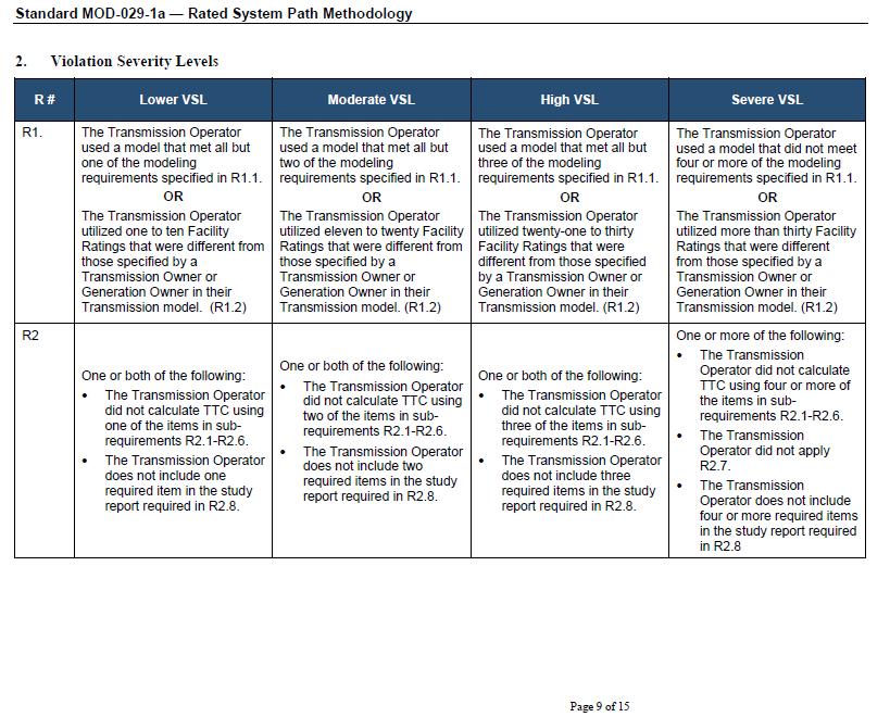
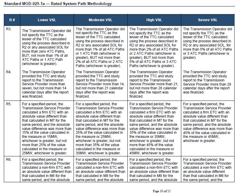
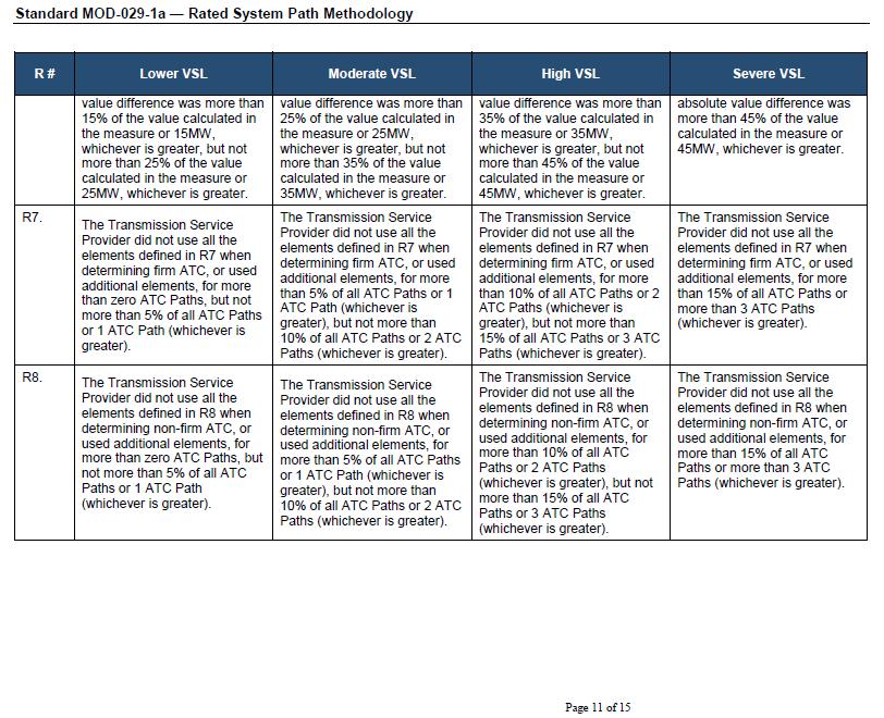
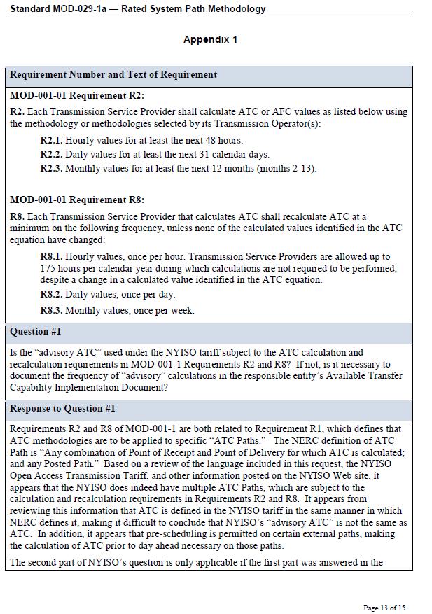
19 Appendix B: Standard MOD-029-1a Rated System Path Methodology
20 - 19 -
21 - 20 -
22 - 21 -
23 - 22 -
24 - 23 -
25 - 24 -
26 - 25 -
27 - 26 -
28 - 27 -
29 - 28 -
30 - 29 -
31 - 30 -
32 - 31 -
33 - 32 -
34 - 33 -
MidAmerican Energy Company Reliability Planning Criteria for 100 kv and Above
 MidAmerican Energy Company Reliability Planning Criteria for 100 kv and Above March 13, 2018 Issued by: Dehn Stevens, Director System Planning and Services 1.0 SCOPE This document defines the criteria
ITC Holdings Planning Criteria Below 100 kv. Category: Planning. Eff. Date/Rev. # 12/09/
 ITC Holdings Planning Criteria Below 100 kv * Category: Planning Type: Policy Eff. Date/Rev. # 12/09/2015 000 Contents 1. Goal... 2 2. Steady State Voltage & Thermal Loading Criteria... 2 2.1. System Loading...
Central Hudson Gas & Electric Corporation. Transmission Planning Guidelines
 Central Hudson Gas & Electric Corporation Transmission Planning Guidelines Version 4.0 March 16, 2016 Version 3.0 March 16, 2009 Version 2.0 August 01, 1988 Version 1.0 June 26, 1967 Table of Contents
DUKE ENERGY CAROLINAS TRANSMISSION SYSTEM PLANNING GUIDELINES. Transmission Planning
 DUKE ENERGY CAROLINAS TRANSMISSION SYSTEM PLANNING GUIDELINES Transmission Planning TABLE OF CONTENTS I. SCOPE 1 II. TRANSMISSION PLANNING OBJECTIVES 2 III. PLANNING ASSUMPTIONS 3 A. Load Levels 3 B. Generation
GridLiance Reliability Criteria
 GridLiance Reliability Criteria Planning Department March 1, 2018 FOREWORD The GridLiance system is planned, designed, constructed, and operated to assure continuity of service during system disturbances
Standard PRC Generator Frequency and Voltage Protective Relay Settings. A. Introduction
 A. Introduction 1. Title: Generator Frequency and Voltage Protective Relay Settings 2. Number: PRC-024-1 3. Purpose: Ensure Generator Owners set their generator protective relays such that generating units
ESB National Grid Transmission Planning Criteria
 ESB National Grid Transmission Planning Criteria 1 General Principles 1.1 Objective The specific function of transmission planning is to ensure the co-ordinated development of a reliable, efficient, and
Document C-29. Procedures for System Modeling: Data Requirements & Facility Ratings. January 5 th, 2016 TFSS Revisions Clean Open Process Posting
 Document C-29 Procedures for System Modeling: January 5 th, 2016 TFSS Revisions Clean Open Process Posting Prepared by the SS-37 Working Group on Base Case Development for the Task Force on System Studies.
PRC Generator Relay Loadability. A. Introduction 1. Title: Generator Relay Loadability 2. Number: PRC-025-1
 PRC-025-1 Generator Relay Loadability A. Introduction 1. Title: Generator Relay Loadability 2. Number: PRC-025-1 Purpose: To set load-responsive protective relays associated with generation Facilities
Standard PRC Generator Frequency and Voltage Protective Relay Settings. A. Introduction. See the Implementation Plan for PRC
 A. Introduction 1. Title: Generator Frequency and Voltage Protective Relay Settings 2. Number: PRC-024-2 3. Purpose: Ensure Generator Owners set their generator protective relays such that generating units
System Operating Limit Definition and Exceedance Clarification
 System Operating Limit Definition and Exceedance Clarification The NERC-defined term System Operating Limit (SOL) is used extensively in the NERC Reliability Standards; however, there is much confusion
Final ballot January BOT adoption February 2015
 Standard PRC-024-21(X) Generator Frequency and Voltage Protective Relay Settings Standard Development Timeline This section is maintained by the drafting team during the development of the standard and
PRC Generator Relay Loadability. A. Introduction 1. Title: Generator Relay Loadability 2. Number: PRC-025-1
 A. Introduction 1. Title: Generator Relay Loadability 2. Number: PRC-025-1 Purpose: To set load-responsive protective relays associated with generation Facilities at a level to prevent unnecessary tripping
Standard Development Timeline
 Standard Development Timeline This section is maintained by the drafting team during the development of the standard and will be removed when the standard is adopted by the Board of Trustees. Description
Standard MOD Area Interchange Methodology
 A. Introduction 1. Title: Area Interchange Methodology 2. Number: MOD-028-2 3. Purpose: To increase consistency and reliability in the development and documentation of Transfer Capability calculations
ISO Rules Part 500 Facilities Division 502 Technical Requirements Section Aggregated Generating Facilities Technical Requirements
 Division 502 Technical Applicability 1(1) Section 502.1 applies to: Expedited Filing Draft August 22, 2017 the legal owner of an aggregated generating facility directly connected to the transmission system
PRC Generator Relay Loadability. Guidelines and Technical Basis Draft 4: (June 10, 2013) Page 1 of 75
 Page 1 of 75") PRC-025-1 Introduction The document, Power Plant and Transmission System Protection Coordination, published by the NERC System Protection and Control Subcommittee (SPCS) provides extensive general discussion
PRC-025-1 Introduction The document, Power Plant and Transmission System Protection Coordination, published by the NERC System Protection and Control Subcommittee (SPCS) provides extensive general discussion
Texas Reliability Entity Event Analysis. Event: May 8, 2011 Loss of Multiple Elements Category 1a Event
 Texas Reliability Entity Event Analysis Event: May 8, 2011 Loss of Multiple Elements Category 1a Event Texas Reliability Entity July 2011 Page 1 of 10 Table of Contents Executive Summary... 3 I. Event
Wind Power Facility Technical Requirements CHANGE HISTORY
 CHANGE HISTORY DATE VERSION DETAIL CHANGED BY November 15, 2004 Page 2 of 24 TABLE OF CONTENTS LIST OF TABLES...5 LIST OF FIGURES...5 1.0 INTRODUCTION...6 1.1 Purpose of the Wind Power Facility Technical
PRC Generator Relay Loadability. Guidelines and Technical Basis Draft 5: (August 2, 2013) Page 1 of 76
 Page 1 of 76") PRC-025-1 Introduction The document, Power Plant and Transmission System Protection Coordination, published by the NERC System Protection and Control Subcommittee (SPCS) provides extensive general discussion
PRC-025-1 Introduction The document, Power Plant and Transmission System Protection Coordination, published by the NERC System Protection and Control Subcommittee (SPCS) provides extensive general discussion
(Circuits Subject to Requirements R1 R5) Generator Owner with load-responsive phase protection systems as described in
 Generator Owner with load-responsive phase protection systems as described in") A. Introduction 1. Title: Transmission Relay Loadability 2. Number: PRC-023-3 3. Purpose: Protective relay settings shall not limit transmission loadability; not interfere with system operators ability
A. Introduction 1. Title: Transmission Relay Loadability 2. Number: PRC-023-3 3. Purpose: Protective relay settings shall not limit transmission loadability; not interfere with system operators ability
ISO Rules Part 500 Facilities Division 502 Technical Requirements Section Wind Aggregated Generating Facilities Technical Requirements
 Applicability 1(1) Section 502.1 applies to the ISO, and subject to the provisions of subsections 1(2), (3) and (4) to any: (a) a new wind aggregated generating facility to be connected to the transmission
NORMES DE FIABILITÉ DE LA NERC (VERSION ANGLAISE)
") COORDONNATEUR DE LA FIABILITÉ Direction Contrôle des mouvements d énergie Demande R-3944-2015 NORMES DE FIABILITÉ DE LA NERC (VERSION ANGLAISE) Original : 2016-10-14 HQCMÉ-10, Document 2 (En liasse) Standard
COORDONNATEUR DE LA FIABILITÉ Direction Contrôle des mouvements d énergie Demande R-3944-2015 NORMES DE FIABILITÉ DE LA NERC (VERSION ANGLAISE) Original : 2016-10-14 HQCMÉ-10, Document 2 (En liasse) Standard
Transmission Interconnection Requirements for Inverter-Based Generation
 Transmission Requirements for Inverter-Based Generation June 25, 2018 Page 1 Overview: Every generator interconnecting to the transmission system must adhere to all applicable Federal and State jurisdictional
Massive Transient Stability Based Cascading Analysis and On-line Identification of Critical Cascades
 1 Massive Transient Stability Based Cascading Analysis and On-line Identification of Critical Cascades Paper Number: 16PESGM2419 Marianna Vaiman, V&R Energy marvaiman@vrenergy.com 2016 IEEE PES General
AMEREN s (On Behalf of Its Transmission Owning Affiliates, Including Ameren Missouri, Ameren Illinois, and Ameren Transmission Company of Illinois)
") AMEREN s (On Behalf of Its Transmission Owning Affiliates, Including Missouri, Illinois, and Transmission Company of Illinois) TRANSMISSION PLANNING CRITERIA AND GUIDELINES March 28, 2003 Revised April
AMEREN s (On Behalf of Its Transmission Owning Affiliates, Including Missouri, Illinois, and Transmission Company of Illinois) TRANSMISSION PLANNING CRITERIA AND GUIDELINES March 28, 2003 Revised April
FACILITY RATINGS METHOD TABLE OF CONTENTS
 FACILITY RATINGS METHOD TABLE OF CONTENTS 1.0 PURPOSE... 2 2.0 SCOPE... 3 3.0 COMPLIANCE... 4 4.0 DEFINITIONS... 5 5.0 RESPONSIBILITIES... 7 6.0 PROCEDURE... 8 6.4 Generating Equipment Ratings... 9 6.5
TECHNICAL SPECIFICATIONS AND OPERATING PROTOCOLS AND PROCEDURES FOR INTERCONNECTION OF GENERATION FACILITIES NOT SUBJECT TO FERC JURISDICTION
 TECHNICAL SPECIFICATIONS AND OPERATING PROTOCOLS AND PROCEDURES FOR INTERCONNECTION OF GENERATION FACILITIES NOT SUBJECT TO FERC JURISDICTION Document 9022 Puget Sound Energy, Inc. PSE-TC-160.70 December
MidAmerican Energy Company 100 kv and Above Facility Ratings Methodology
 MidAmerican Energy Company 100 kv and Above Facility Ratings Methodology For NERC Standard FAC-008 and FAC-009 Issued by: Dan Custer Reviewed by: Tom Mielnik Version 2.7 1 1.0 Scope: This document provides
Southern Company Interconnection Requirements for Inverter-Based Generation
 Southern Company Interconnection Requirements for Inverter-Based Generation September 19, 2016 Page 1 of 16 All inverter-based generation connected to Southern Companies transmission system (Point of Interconnection
1
 Guidelines and Technical Basis Introduction The document, Power Plant and Transmission System Protection Coordination, published by the NERC System Protection and Control Subcommittee (SPCS) provides extensive
CAISO Restricted - Do Not Distribute Outside of RC Project LOI and NDA Entities Page 1 of 24
 RC0120A - RC IRO-010 Data Specification NOTE: Changes from Peak's Attachment A are highlighted in red in columns C through G Section Category Number Responsible Pa Data Item Data Transfer Method 1.1 Transmission
Central East Voltage and Stability Analysis for Marcy FACTS Project Phase I
 Prepared by NYISO Operations Engineering 1. INTRODUCTION Central East Voltage and Stability Analysis for The Marcy Flexible AC Transmission System (FACTS) project is a joint technology partnership between
PJM Manual 07:: PJM Protection Standards Revision: 2 Effective Date: July 1, 2016
 PJM Manual 07:: PJM Protection Standards Revision: 2 Effective Date: July 1, 2016 Prepared by System Planning Division Transmission Planning Department PJM 2016 Table of Contents Table of Contents Approval...6
1st Qua u r a ter e M e M e e t e in i g 2nd Qua u r a ter e M e M e e t e in i g
 2011 SERTP Welcome SERTP 2011 First RPSG Meeting & Interactive Training Session 9:00 AM 3:00 PM 1 2011 SERTP The SERTP process is a transmission planning process. Please contact the respective transmission
generation greater than 75 MVA (gross aggregate nameplate rating) Generation in the ERCOT Interconnection with the following characteristics:
 Generation in the ERCOT Interconnection with the following characteristics:") A. Introduction 1. Title: Verification of Models and Data for Turbine/Governor and Load Control or Active Power/Frequency Control Functions 2. Number: MOD-027-1 3. Purpose: To verify that the turbine/governor
A. Introduction 1. Title: Verification of Models and Data for Turbine/Governor and Load Control or Active Power/Frequency Control Functions 2. Number: MOD-027-1 3. Purpose: To verify that the turbine/governor
Real Time Stability Analysis at Peak Reliability. Slaven Kincic, Hongming Zhang JSIS May 2017, SLC
 Real Time Stability Analysis at Peak Reliability Slaven Kincic, Hongming Zhang JSIS May 2017, SLC Overview: Overview of Peak s DSA Application; o Set up o User Cases Transient Stability Criteria; TSAT
Appendix S: PROTECTION ALTERNATIVES FOR VARIOUS GENERATOR CONFIGURATIONS
 Appendix S: PROTECTION ALTERNATIVES FOR VARIOUS GENERATOR CONFIGURATIONS S1. Standard Interconnection Methods with Typical Circuit Configuration for Single or Multiple Units Note: The protection requirements
Kansas City Power & Light Company. Transmission Facility Rating Methodology
 Company Prepared by: KCP&L Transmission Planning December 6, 2017 Table of Contents 1. Purpose...4 2. Generator Rating Methodology...4 3....4 3.1. Equipment Rating Methodology...4 3.2. Items considered
EH2741 Communication and Control in Electric Power Systems Lecture 2
 KTH ROYAL INSTITUTE OF TECHNOLOGY EH2741 Communication and Control in Electric Power Systems Lecture 2 Lars Nordström larsno@kth.se Course map Outline Transmission Grids vs Distribution grids Primary Equipment
Voltage and Reactive Procedures CMP-VAR-01
 Voltage and Reactive Procedures CMP-VAR-01 NERC Standards: VAR-001-2 VAR-002-1.1b Effective Date: 07/31/2012 Document Information Current Revision 2.0 Review Cycle Annual Subject to External Audit? Yes
MidAmerican Energy Company 69 kv Facility Ratings Methodology
 MidAmerican Energy Company 69 kv Facility Ratings Methodology Version 1.0 Issued by: Luke Erichsen Reviewed by: Tom Mielnik Last Reviewed: 8/29/2012 1 1.0 Scope: This document provides MidAmerican Energy
Planning Criteria. Revision 1.4 MAINTAINED BY: Transmission Working Group System Protection and Control Working Group Supply Adequacy Working Group
 Planning Criteria Revision 1.4 MAINTAINED BY: Transmission Working Group System Protection and Control Working Group Supply Adequacy Working Group PUBLISHED: 10/9/2017 LATEST REVISION: Effective 7/25/2017
VAR Voltage and Reactive Control
 VAR-001-4 Voltage and Reactive Control A. Introduction 1. Title: Voltage and Reactive Control 2. Number: VAR-001-4 3. Purpose: To ensure that voltage levels, reactive flows, and reactive resources are
A. Introduction. VAR Voltage and Reactive Control
 A. Introduction 1. Title: Voltage and Reactive Control 2. Number: VAR-001-4.2 3. Purpose: To ensure that voltage levels, reactive flows, and reactive resources are monitored, controlled, and maintained
Power System Protection Where Are We Today?
 1 Power System Protection Where Are We Today? Meliha B. Selak Power System Protection & Control IEEE PES Distinguished Lecturer Program Preceding IEEE PES Vice President for Chapters melihas@ieee.org PES
Notes 1: Introduction to Distribution Systems
 Notes 1: Introduction to Distribution Systems 1.0 Introduction Power systems are comprised of 3 basic electrical subsystems. Generation subsystem Transmission subsystem Distribution subsystem The subtransmission
Unit Auxiliary Transformer (UAT) Relay Loadability Report
 Relay Loadability Report") Background and Objective Reliability Standard, PRC 025 1 Generator Relay Loadability (standard), developed under NERC Project 2010 13.2 Phase 2 of Relay Loadability: Generation, was adopted by the NERC
Background and Objective Reliability Standard, PRC 025 1 Generator Relay Loadability (standard), developed under NERC Project 2010 13.2 Phase 2 of Relay Loadability: Generation, was adopted by the NERC
ReliabilityFirst Regional Criteria 1. Disturbance Monitoring and Reporting Criteria
 ReliabilityFirst Regional Criteria 1 Disturbance Monitoring and Reporting Criteria 1 A ReliabilityFirst Board of Directors approved good utility practice document which are not reliability standards. ReliabilityFirst
Power System Stability. Course Notes PART-1
 PHILADELPHIA UNIVERSITY ELECTRICAL ENGINEERING DEPARTMENT Power System Stability Course Notes PART-1 Dr. A.Professor Mohammed Tawfeeq Al-Zuhairi September 2012 1 Power System Stability Introduction Dr.Mohammed
Standard VAR Voltage and Reactive Control
 A. Introduction 1. Title: Voltage and Reactive Control 2. Number: VAR-001-3 3. Purpose: To ensure that voltage levels, reactive flows, and reactive resources are monitored, controlled, and maintained within
TECHNICAL SPECIFICATIONS AND OPERATING PROTOCOLS AND PROCEDURES FOR INTERCONNECTION OF LARGE GENERATION FACILITIES. Document 9020
 TECHNICAL SPECIFICATIONS AND OPERATING PROTOCOLS AND PROCEDURES FOR INTERCONNECTION OF LARGE GENERATION FACILITIES Document 9020 Puget Sound Energy, Inc. PSE-TC-160.50 December 19, 2016 TABLE OF CONTENTS
VAR Generator Operation for Maintaining Network Voltage Schedules
 Standard Development Timeline This section is maintained by the drafting team during the development of the standard and will be removed when the standard becomes effective. Development Steps Completed
VAR Voltage and Reactive Control. A. Introduction
 VAR-001-5 Voltage and Reactive Control A. Introduction 1. Title: Voltage and Reactive Control 2. Number: VAR-001-5 3. Purpose: To ensure that voltage levels, reactive flows, and reactive resources are
ROCHESTER PUBLIC UTILITIES FACILITY RATINGS METHODOLOGY FOR TRANSMISSION, SUBSTATION, & GENERATION EQUIPMENT
 ROCHESTER PUBLIC UTILITIES FACILITY RATINGS METHODOLOGY FOR TRANSMISSION, SUBSTATION, & GENERATION EQUIPMENT Page 1 of 8 The document describes the current methodology used for developing facility ratings
Arizona Public Service Company and the Transmission Partnership for National Electric Power Company of Jordan
 Arizona Public Service Company and the Transmission Partnership for National Electric Power Company of Jordan Mark Hackney October 5-8, 2009 Amman, Jordan Energy Control Center Layout 2 Energy Control
I WP Asset # I ~:2 3. I Review Annual. ~c~~ Date: 'l/j(j/! ZL>IJ,...
 - District Standard - FAC Facility Design, Connections 950.001 and Maintenance CHELAN COUNTY ~ PUBLIC UTILITY DISTRICT Owned By The People~ Serve Facility Connection Requirements Page 1 of 101 EFFECTIVE
ATCO ELECTRIC LTD. (Transmission System) SERVICE QUALITY AND RELIABILITY PERFORMANCE, MEASURES AND INDICES Revision 0
 SERVICE QUALITY AND RELIABILITY PERFORMANCE, MEASURES AND INDICES Revision 0") ATCO ELECTRIC LTD. (Transmission System) SERVICE QUALITY AND RELIABILITY PERFORMANCE, MEASURES AND INDICES 2014-03-31 - Revision 0 EUB Decision 2007-071 Board Direction 52 For questions or comments regarding
ATCO ELECTRIC LTD. (Transmission System) SERVICE QUALITY AND RELIABILITY PERFORMANCE, MEASURES AND INDICES 2014-03-31 - Revision 0 EUB Decision 2007-071 Board Direction 52 For questions or comments regarding
Transmission Facilities Rating Methodology for Florida
 Document title Transmission Facilities Rating Methodology for Florida Document number EGR-TRMF-00001 Applies to: Transmission Engineering, Transmission System Operations, and Transmission Planning Duke
ATTACHMENT Y STUDY REPORT
 Dynegy Marketing and Trade, LLC Wood River Units 4 & 5: 473 MW Retirement: June 1, 2016 ATTACHMENT Y STUDY REPORT March 23, 2016 PUBLIC / REDACTED PUBLIC VERSION EXECUTIVE SUMMARY An Attachment Y notification
Standard VAR-002-2b(X) Generator Operation for Maintaining Network Voltage Schedules. 45-day Formal Comment Period with Initial Ballot June July 2014
 Generator Operation for Maintaining Network Voltage Schedules. 45-day Formal Comment Period with Initial Ballot June July 2014") Standard Development Timeline This section is maintained by the drafting team during the development of the standard and will be removed when the standard becomes effective. Development Steps Completed
Standard Development Timeline This section is maintained by the drafting team during the development of the standard and will be removed when the standard becomes effective. Development Steps Completed
NERC Requirements for Setting Load-Dependent Power Plant Protection: PRC-025-1
 NERC Requirements for Setting Load-Dependent Power Plant Protection: PRC-025-1 Charles J. Mozina, Consultant Beckwith Electric Co., Inc. www.beckwithelectric.com I. Introduction During the 2003 blackout,
Standard VAR-002-2b(X) Generator Operation for Maintaining Network Voltage Schedules
 Generator Operation for Maintaining Network Voltage Schedules") Standard Development Timeline This section is maintained by the drafting team during the development of the standard and will be removed when the standard becomes effective. Development Steps Completed
Standard Development Timeline This section is maintained by the drafting team during the development of the standard and will be removed when the standard becomes effective. Development Steps Completed
FOUR TOTAL TRANSFER CAPABILITY. 4.1 Total transfer capability CHAPTER
 CHAPTER FOUR TOTAL TRANSFER CAPABILITY R structuring of power system aims at involving the private power producers in the system to supply power. The restructured electric power industry is characterized
High Voltage DC Transmission Prof. Dr. S. N. Singh Department of Electrical Engineering Indian Institute of Technology, Kanpur
 High Voltage DC Transmission Prof. Dr. S. N. Singh Department of Electrical Engineering Indian Institute of Technology, Kanpur Module No. # 01 Lecture No. # 02 Comparison of HVAC and HVDC Systems Welcome
MANITOBA HYDRO TRANSMISSION SYSTEM INTERCONNECTION REQUIREMENTS. July 2016 Version 4
 MANITOBA HYDRO TRANSMISSION SYSTEM INTERCONNECTION REQUIREMENTS July 2016 Version 4 This page intentionally blank LEGISLATIVE AUTHORITY Section 15.0.3(1) of The Manitoba Hydro Act (C.C.S.M. c. H190) authorizes
Standard MOD Verification of Models and Data for Generator Excitation Control System or Plant Volt/Var Control Functions
 Standard MOD-026-1 Verification of Models and Data for Generator Excitation Control System or Plant Volt/Var Control Functions A. Introduction 1. Title: Verification of Models and Data for Generator Excitation
August 25, Please contact the undersigned if you have any questions concerning this filing.
 !! August 25, 2017 VIA ELECTRONIC FILING Ms. Erica Hamilton, Commission Secretary British Columbia Utilities Commission Box 250, 900 Howe Street Sixth Floor Vancouver, B.C. V6Z 2N3 Re: North American Electric
ISO Rules Part 500 Facilities Division 502 Technical Requirements Section SCADA Technical and Operating Requirements
 Section 502.8 SCADA Technical and Operating Applicability 1 Section 502.8 applies to: (a) the legal owner of a generating unit: (i) connected to the transmission facilities in the balancing authority area
Endorsed Assignments from ERS Framework
 ERSTF Completion Endorsed Assignments from ERS Framework Ref Number Title ERS Recommendatio n Ongoing Responsibility 1 Synch Inertia at Interconnection Level Measure 2 Initial Frequency Deviation Measure
NPCC Regional Reliability Reference Directory # 12. Underfrequency Load Shedding Program Requirements
 NPCC Regional Reliability Reference Directory # 12 Under frequency Load Shedding Program Requirements Task Force on System Studies Revision Review Record: June 26 th, 2009 March 3 rd, 2010 Adopted by the
Implementation Plan Project Alignment of Terms
 Revisions to Defined Terms in the NERC Glossary of Terms Used in Reliability Standards The drafting team proposes modifying the following Glossary of Terms definitions: Blackstart Resource
SYNCHROPHASOR TECHNOLOGY GLOSSARY Revision Date: April 24, 2011
 SYNCHROPHASOR TECHNOLOGY GLOSSARY Revision Date: April 24, 2011 Baselining using large quantities of historical phasor data to identify and understand patterns in interconnection-wide grid behavior, to
Table of Contents. Introduction... 1
 Table of Contents Introduction... 1 1 Connection Impact Assessment Initial Review... 2 1.1 Facility Design Overview... 2 1.1.1 Single Line Diagram ( SLD )... 2 1.1.2 Point of Disconnection - Safety...
VAR Generator Operation for Maintaining Network Voltage Schedules
 A. Introduction 1. Title: Generator Operation for Maintaining Network Voltage Schedules 2. Number: VAR-002-4 3. Purpose: To ensure generators provide reactive support and voltage control, within generating
Recently, the SS38 Working Group on Inter-Area Dynamic Analysis completed two study reports on behalf of the UFLS Regional Standard Drafting Team.
 December 7 th, 2010 NPCC Full Member Committee; Please find attached a draft revised NPCC Regional Reliability Directory #12 Underfrequency Load Shedding Program Requirements and a draft revised NPCC UFLS
IDAHO PURPA GENERATOR INTERCONNECTION REQUEST (Application Form)
") IDAHO PURPA GENERATOR INTERCONNECTION REQUEST (Application Form) Transmission Provider: IDAHO POWER COMPANY Designated Contact Person: Jeremiah Creason Address: 1221 W. Idaho Street, Boise ID 83702 Telephone
IDAHO PURPA GENERATOR INTERCONNECTION REQUEST (Application Form) Transmission Provider: IDAHO POWER COMPANY Designated Contact Person: Jeremiah Creason Address: 1221 W. Idaho Street, Boise ID 83702 Telephone
August 25, 2017 VIA ELECTRONIC FILING
 !! August 25, 2017 VIA ELECTRONIC FILING Kirsten Walli, Board Secretary Ontario Energy Board P.O Box 2319 2300 Yonge Street Toronto, Ontario, Canada M4P 1E4 Re: North American Electric Reliability Corporation
Generation and Load Interconnection Standard
 Generation and Load Interconnection Standard Rev. 0A DRAFT Name Signature Date Prepared: Approved: VP Acceptance APEGGA Permit to Practice P-08200 TABLE OF CONTENTS 1.0 INTRODUCTION...5 1.1 Purpose...5
LONG-RANGE TRANSMISSION PLAN
 LONG-RANGE TRANSMISSION PLAN 2011-2020 Transmission and Substation Engineering Department August 15, 2011 TABLE OF CONTENTS EXECUTIVE SUMMARY Page i I. OVERVIEW 1 A. Factors Affecting the Long Range Transmission
Northeast Power Coordinating Council, Inc. Glossary of Terms. Approved by the Reliability Standards Committee
 Northeast Power Coordinating Council, Inc. Glossary of Terms Approved by the Reliability Standards Committee October 26, 2011 Revision History Version Date Action Change Tracking (New, Errata or Revisions)
Overview. The Principles of Power System Operation module presents the following topics:
 Course Outline 1. Introduction to WECC 2. Fundamentals of Electricity 3. Power System Overview 4. Principles of Generation 5. Substation Overview 6. Transformers 7. Power Transmission 8. System Protection
ISO Rules Part 500 Facilities Division 502 Technical Requirements Section SCADA Technical and Operating Requirements
 Section 502.8 SCADA Technical and Operating Requirements Applicability 1 Subject to subsections 2 and 3 below, section 502.8 applies to: (a) (c) (d) the legal owner of a generating unit or an aggregated
Available Transfer Capability (ATC) EE 521 Analysis of Power Systems Chen-Ching Liu Washington State University
 EE 521 Analysis of Power Systems Chen-Ching Liu Washington State University") Available Transfer Capability (ATC) EE 521 Analysis of Power Systems Chen-Ching Liu Washington State University i Available Transfer Capability (ATC) ATC measures the residual transfer capability in the
Available Transfer Capability (ATC) EE 521 Analysis of Power Systems Chen-Ching Liu Washington State University i Available Transfer Capability (ATC) ATC measures the residual transfer capability in the
Transmission System Phase Backup Protection
 Reliability Guideline Transmission System Phase Backup Protection NERC System Protection and Control Subcommittee Draft for Planning Committee Approval June 2011 Table of Contents 1. Introduction and Need
Power Plant and Transmission System Protection Coordination
 Technical Reference Document Power Plant and Transmission System Protection Coordination NERC System Protection and Control Subcommittee Revision 1 July 2010 Table of Contents 1. Introduction... 1 1.1.
GENERAL REQUIREMENTS FOR TRANSMISSION INTERCONNECTION
 GENERAL REQUIREMENTS FOR TRANSMISSION INTERCONNECTION May 31 st, 2017 Rev. 04 Public Utility District No. 2 of Grant County P.O. Box 878, Ephrata, WA 98823 (509) 754-0500 GENERAL REQUIREMENTS FOR INTERCONNECTION
BC HYDRO REAL TIME OPERATIONS OPERATING ORDER 7T-30A. NORTH COAST INTERCONNECTION: SKEENA BOB QUINN SUBSYSTEM Supersedes OO 7T-30A dated 07 July 2014
 BC HYDRO REAL TIME OPERATIONS OPERATING ORDER 7T-30A NORTH COAST INTERCONNECTION: SKEENA BOB QUINN SUBSYSTEM Supersedes OO 7T-30A dated 07 July 2014 Expiry Year: 2018 APPROVED BY: Original signed by: Paul
CONSOLIDATED EDISON CO. OF NEW YORK, INC 4 IRVING PLACE NEW YORK, N.Y
 CONSOLIDATED EDISON CO. OF NEW YORK, INC 4 IRVING PLACE NEW YORK, N.Y. 10003 EP 7000 5 JULY 2009 VOLTAGE SCHEDULE, CONTROL, AND OPERATION OF THE TRANSMISSION SYSTEM PURPOSE This specification describes
WSAT Online Tool for Assessment of Secure Level of Wind Generation on the System
 WSAT Online Tool for Assessment of Secure Level of Wind Generation on the System Dr Ivan Dudurych 4000 600 3600 480 Load, MW 3200 2800 2400 Load, MW 06/10/2006 Load, MW 29/09/2006 Wind, MW 06/10/2006 Wind,
Embedded Generation Connection Application Form
 Embedded Generation Connection Application Form This Application Form provides information required for an initial assessment of the Embedded Generation project. All applicable sections must be completed
Bulk Electric System Definition Reference Document
 Bulk Electric System Definition Reference Document Version 2 April 2014 This technical reference was created by the Definition of Bulk Electric System drafting team to assist entities in applying the definition.
Facilitating Bulk Wind Power Integration Using LCC HVDC
 21, rue d Artois, F-758 PARIS CIGRE US National Committee http : //www.cigre.org 213 Grid of the Future Symposium Facilitating Bulk Wind Power Integration Using LCC HVDC A. HERNANDEZ * R.MAJUMDER W. GALLI
Linear State Estimation
 Linear State Estimation Marianna Vaiman, V&R Energy marvaiman@vrenergy.com WECC JSIS Meeting Salt Lake City, UT October 15 17, 2013 Copyright 1997-2013 V&R Energy Systems Research, Inc. All rights reserved.
VAR Generator Operation for Maintaining Network Voltage Schedules
 A. Introduction 1. Title: Generator Operation for Maintaining Network Voltage Schedules 2. Number: VAR-002-3 3. Purpose: To ensure generators provide reactive support and voltage control, within generating
Transmission Availability Data Systems Frequently Asked Questions
 Transmission Availability Data Systems Frequently Asked Questions March 2016 NERC Report Title Report Date I Table of Contents Preface... iii Executive Summary... iv Chapter 1 TADS Inventory Related Questions...1
VAR Generator Operation for Maintaining Network Voltage Schedules
 A. Introduction 1. Title: Generator Operation for Maintaining Network Voltage Schedules 2. Number: VAR-002-3 3. Purpose: To ensure generators provide reactive support and voltage control, within generating
Company Directive POLICY DOCUMENT: SD4/7. Relating to 11kV and 6.6kV System Design
 Company Directive POLICY DOCUMENT: SD4/7 Relating to 11kV and 6.6kV System Design Policy Summary This document describes the standard requirements for the design of the 11kV and 6.6kV systems. Reference
TRANSMISSION FACILITIES...7
 Table of Contents 1. INTRODUCTION...4 1.1. Objective... 4 1.2. NERC FAC-008 Compliance... 4 1.3. Seminole s Normal Rating... 5 1.4. Seminole s Four-Hour Rating... 5 1.5. Seminole s Emergency Rating...