Overview. The Principles of Power System Operation module presents the following topics:
|
|
|
- Millicent Owen
- 6 years ago
- Views:
Transcription
1 Course Outline 1. Introduction to WECC 2. Fundamentals of Electricity 3. Power System Overview 4. Principles of Generation 5. Substation Overview 6. Transformers 7. Power Transmission 8. System Protection 9. Principles of System Operation
2 Overview The Principles of Power System Operation module presents the following topics: Balancing Authorities AGC and Energy Balance Interconnected Operations Automatic Generation Control Operating Limits Power System Stability Computer System Functions And a few more topics of interest
3 4 6 Balancing Authority Overview Definition Basic Responsibilities WECC Balancing Authorities Industry Restructuring W E S T E R N E L E C T R I C I T Y C O O R D I N A T I N G C O U N C I L
4 Balancing Authority Overview Definition What Is A Balancing Authority (BA)? A Balancing Authority is defined by a set of resources and interchange meters. Traditional Balancing Authorities have dispatchable generation, load, and interchange.
5 Balancing Authorities Balancing Authority A M Balancing Authority C M M M Balancing Authority D M M Balancing Authority B M Balancing Authority E M M = meter
6 Balancing Authority Overview Basic Responsibilities Why Balancing Authorities Are Needed: Load and Generation Balancing Required for good control of frequency Short term balancing called load-frequency regulation. Longer term balancing is called load following. Balancing Authorities and their AGC systems coordinate this control.
7 Balancing Authority Overview Basic Responsibilities Balance Load, Generation, and Net Interchange. Control Frequency and Time Error. Implement Interchange Transactions.

8 Balancing Authority Overview WECC Balancing Authorities
9 Balancing Authority Overview Industry Restructuring Balancing Authorities Reliability Coordinators Interchange Coordinators Transmission Operators Independent System Operators (ISO) Regional Transmission Organizations (RTO)
10 Check Your Knowledge: Balancing Authority Overview 1. How many Balancing Authorities are in the Western Interconnection? 2. What do BAs balance? 3. How does a generation-only BA balance load and generation? W E S T E R N E L E C T R I C I T Y C O O R D I N A T I N G C O U N C I L
11 7 Automatic Generation Control (AGC) Basics Scheduled and Actual Interchange Turbine Governor Controls Area Control Error Sample Automatic Generator Control Response NERC / WECC Control Criteria Time Error
12 Automatic Generation Control (AGC) Basics Scheduled Interchange How Do We Do Interchange? How do we get 100 MW of power to flow from Balancing Authority A to B? Scenario: A generates 100 MW more than its load. B generates 100 MW less than its load. Excess MW from A serves the deficiency in B.
13 Automatic Generation Control (AGC) Basics Scheduled Interchange What is Scheduled Interchange? An agreement to exchange a specified amount of power for an agreed upon period of time. Balancing Authorities implement the schedule in a coordinated manner.
14 Automatic Generation Control (AGC) Basics Actual Interchange What is Actual Interchange? Measured MW flow between balancing authorities. Uses interchange meters on lines establishing the balancing authority boundaries. Flows are not always intentional
15 Automatic Generation Control (AGC) Basics Actual Interchange Computing BA Area Load M Balancing Authority M M Interchange Generation M M BA Load = (Generation) (Net Interchange)
16 Automatic Generation Control (AGC) Basics A Matter of Balance Frequency 60 Load Generation
17 Automatic Generation Control (AGC) Basics Turbine Governor Controls Generating Unit Controls R L Speed Changer Motor R L f Moveable collar Increasing speed decreases turbine input Steam Turbine Generator A generator will increase output when it sees low frequency A generator will decrease output when it sees high frequency Governor action takes place without control center instruction.
18
19 Automatic Generation Control (AGC) Basics Area Control Error (ACE) Measures whether Balancing Authority is properly generating its MW requirements. Factors in required actions to help control interconnection frequency.
20 AGC Control Modes Tie line bias control is the normal mode used. It uses both frequency and tie-line power flow to calculate ACE. A more descriptive term for this control mode is constant net interchange with frequency bias. It recognizes the following: If frequency decreases and the power leaving the system increases (or power entering the system decreases), then the need for power is outside the Balancing Authority. If frequency decreases and the power leaving the system decreases (or power entering the system increases), then the need for power is inside the Balancing Authority.
21 AGC Control Modes Flat frequency control responds only to frequency changes. It does not respond to power flow changes on tie lines. This mode is used only on an isolated system, since it could lead to overloading tie lines while correcting frequency in an interconnected system. Flat tie line control responds only to changes in power flow on tie lines. It does not respond to changes in frequency. To prevent large frequency deviations, it is used only for brief periods when a frequency measurement is not available.
22 Automatic Generation Control (AGC) Basics ACE Equation ACE = (NI A - NI S ) (10B x (F A - F S )) Tie-line error factor Frequency error factor Negative ACE = under-generation Positive ACE = over-generation
23 1 Initial Conditions Frequency OK Tie Line Error? NO Balancing Authority A Gen = 5000 MW Load = 4000 MW Schedule = 1000 MW Actual = 1000 MW M Telemetry Balancing Authority B Gen = 2000 MW Load = 3000 MW A s control action due to: B s control action due to: Tie Line Error Frequency Error NONE NONE Tie Line Error Frequency Error NONE NONE
24 2 Load Jumps 300MW in Balancing Area A Frequency Low Tie Line Error? Yes Balancing Authority A Gen = 5225 MW Gen = 5000 MW Load = 4300 MW Schedule = 1000 MW Actual = 925 MW M Telemetry Balancing Authority B Gen = 2075 MW Gen = 2000 MW Load = 3000 MW A s control action due to: Tie Line Error Frequency Error =increase generation B s control action due to: Tie Line Error Frequency Error =decrease generation
25 3 Nearing new steady state Frequency Low Tie Line Error? Yes Balancing Authority A Gen = 5280 MW Load = 4300 MW Schedule = 1000 MW Actual = 980 MW M Telemetry Balancing Authority B Gen = 2020 MW Load = 3000 MW A s control action due to: Tie Line Error Frequency Error =increase generation B s control action due to: Tie Line Error Frequency Error =decrease generation

26 4 New steady state Frequency OK Tie Line Error? NO Balancing Authority A Gen = 5300 MW Load = 4300 MW Schedule = 1000 MW Actual = 1000 MW M Telemetry Balancing Authority B Gen = 2000 MW Load = 3000 MW A s control action due to: B s control action due to: Tie Line Error Frequency Error NONE NONE Tie Line Error Frequency Error NONE NONE =increase generation =decrease generation
27 Automatic Generation Control (AGC) Basics Sample Automatic Generator Control Response Frequency Disturbance Sequence Somewhere in the system, a generator trips. Stored energy (inertia) from all rotating mass in system replaces lost generation. Increased MW output without increased mechanical input slows the interconnected system (frequency drops). All generator governors act to stop frequency decline. AGC of deficient system eventually reacts to restore frequency.
28
29
30 Automatic Generation Control (AGC) Basics NERC / WECC Control Criteria Measures a Balancing Authority s control performance over time Non-compliance can result in monetary penalties Two Control Performance Standards serve as measures CPS1 CPS2
31 Automatic Generation Control (AGC) Basics NERC / WECC Control Criteria CPS1 Helping or hurting frequency? Control errors of moderate magnitude are acceptable Control errors helping frequency are good. (over-generating when frequency is low, under-generating when frequency is high) Control errors hurting the frequency are bad. (over-generating when frequency is high, under-generating when frequency is low) 33 W E S T E R N E L E C T R I C I T Y C O O R D I N A T I N G C O U N C I L
32 Automatic Generation Control (AGC) Basics NERC / WECC Control Criteria CPS1 Help the Frequency! Starting with a nominal value of 200%, your score goes up when you help the frequency, and your score goes down when you hurt the frequency. At 200% your frequency is on schedule and your ACE is zero. 100% is the minimum acceptable control average.
33 Automatic Generation Control (AGC) Basics NERC / WECC Control Criteria CPS2 Magnitude of ACE over time Over a 10-minute period, the average ACE may not exceed a threshold value called L 10. L 10 values are unique to each Balancing authority

34 Note: Note: Assume Assume Frequency Frequency is LOW is during LOW entire during period. entire period Control Performance Example L 10 L 10 Good Control CPS1, CPS2 OK Time CPS1 OK CPS2 Violations CPS1 Violations CPS2 Violations
35 Automatic Generation Control (AGC) Basics Time Error Operation at other than 60Hz results in time error Low frequency-time is slow High frequency-time is fast Large time error accumulations are a sign of poor Interconnection control performance.
36 Automatic Generation Control (AGC) Basics Time Error Scheduled frequency altered Hz to correct slow time Hz to correct fast time Automatic time error (ATEC) Added component to ACE equation
37 Check Your Knowledge: AGC Basics 1. What does AGC stand for? 2. How does the system know you plugged your vacuum in? 3. How do different types of generation respond to AGC? W E S T E R N E L E C T R I C I T Y C O O R D I N A T I N G C O U N C I L
38 8 Operating Reserves Purpose and type of operating reserves Standards Current issues Reserve Sharing Groups
39 Operating Reserves Purpose and Types Electricity production is an real-time process. Extra generating capacity needs to be readily available. Operating reserves are needed to replace lost generation and supply load increases. All in the name of good frequency control
40 Operating Reserves Purpose and Types Regulating reserve Needed for moment to moment load balancing Used to meet CPS1 and CPS2 Standard Must be spinning Responsive to AGC Have enough to meet CPS1 and CPS2
41 Regulating Reserves For Moment To Moment Load Regulation Load Generation Scheduled imports :00 7:06 7:12 7:18 7:24 7:30 7:36 7:42 7:48 7:54 8:00 Time
42 Operating Reserves Purpose and Types Contingency Reserve Used to replace lost generation Used to meet the Disturbance Control Standard (DCS) Systems can meet requirements collectively Create Reserve Sharing Groups
43 Purpose and Types Operating Reserves Contingencies e.g. generation failures load forecast errors Regulation Frequency ACE
44 OLD - TOTAL OPERATING RESERVE Regulating Reserve Spinning - Meet NERC Criteria 50% Spinning Contingency Reserve = Greater of: 1) Greatest Single Contingency OR 2) 5% Load Responsibility on Hydro PLUS 7% of Load Responsibility on Thermal Plus Additional for Interruptible Imports Plus On Demand Obligations
45 Operating Reserves Purpose and Types New Standard-How much? Greater of: MW loss from single most severe contingency. -or- 3% of hourly integrated load plus 3% of hourly integrated generation
46 Operating Reserves Standards New BAL-002-WECC-2 Standard R1. Each Balancing Authority and each Reserve Sharing Group shall maintain a minimum amount of Contingency Reserve, except within the first sixty minutes following an event requiring the activation of Contingency Reserve, that is: [Violation Risk Factor: High] [Time Horizon: Real-time operations] 1.1 The greater of either: The amount of Contingency Reserve equal to the loss of the most severe single contingency; The amount of Contingency Reserve equal to the sum of three percent of hourly integrated Load plus three percent of hourly integrated generation.
47 Operating Reserves Standards New BAL-002-WECC-2 Standard 1.2 Comprised of any combination of the reserve types specified below: Operating Reserve Spinning Operating Reserve - Supplemental Interchange Transactions designated by the Source Balancing Authority as Operating Reserve Supplemental Reserve held by other entities by agreement that is deliverable on Firm Transmission Service A resource, other than generation or load, that can provide energy or reduce energy consumption Load, including demand response resources, Demand-Side Management resources, Direct Control Load Management, Interruptible Load or Interruptible Demand, or any other Load made available for curtailment by the Balancing Authority or the Reserve Sharing Group via contract or agreement. All other load, not identified above, once the Reliability Coordinator has declared an energy emergency alert signifying that firm load interruption is imminent or in progress.
48 Operating Reserves Standards Disturbance Control Standard (DCS) The ACE must return either to zero or to its predisturbance level within fifteen minutes following the start of the disturbance. Disturbance control standard compliance Each BA or reserve sharing group shall meet the Disturbance Control Standard (DCS) 100% of the time for reportable disturbances. Reportable disturbance reporting threshold events that cause ACE to change by 35% of Most Severe Single Contingency.
49 Operating Reserves Providing Reserves Self supply Market structure California ISO Reserve sharing groups Northwest Power Pool Desert Southwest Reserve Sharing Group Rocky Mountain Reserve Group
50 Check Your Knowledge: Operating Reserves 1. What is the purpose of Operating Reserves? 2. What are 3 types of Operating Reserves? W E S T E R N E L E C T R I C I T Y C O O R D I N A T I N G C O U N C I L
51 Operating Limits Electric current flowing from the generators to the loads follows all available paths. Most current flows over paths that offer the least impedance through conductors, transformers, and other power system components. On well-designed power systems, natural load flows are such that no lines are overloaded under normal circumstances. In some cases, phase-shifting transformers may be required to alter the natural current flows on the transmission system.
52 Operating Limits If a transmission line is opened for any reason, such as a fault, current flows almost instantaneously redistribute over the remaining transmission system. Power systems are generally designed to handle contingencies, such as a line tripping, without overloading any facility. However, this is not always possible, particularly when other lines are already out of service. Therefore, system operators may be required to implement emergency switching actions or arm special remedial action schemes during certain contingencies to prevent equipment loadings from exceeding emergency ratings.
53 Thermal Limits To avoid excessive heating, utilities assign thermal limits or ratings to devices. These limits should not be exceeded. The ratings are based on the amount of heat the device can carry and dissipate. Ratings are expressed in amps, MW, or MVA. Ratings vary with season and the amount of time the device is exposed to the high current.
54 Thermal Limits Each energized device (a circuit breaker, the bus work, transformer, conductor, etc.) has an individual rating. When multiple devices in series (e.g., a transmission line and a series capacitor) have different thermal limits, the most restrictive rating applies to the combination of facilities. Conductor and transformer ratings are typically the most restrictive factors.
55 Annealing The reduction of conductor strength due to annealing over the life of the conductor (annealing is the process of heating and cooling the conductor) The increase in conductor sag due to thermal expansion at high temperatures (minimum conductor-to-ground clearances must be maintained at all times) There are usually several ratings, tailored to local loading and weather conditions that apply to a given line.
56 Normal, Peak & Emergency Ratings Normal rating is the maximum current that can flow on a continuous basis. Peak rating is the current that can be tolerated for a limited time period, usually four hours. In general, the peak rating is higher than the normal rating. Emergency rating is the highest rating of the line. This rating is the maximum current that is permissible for a short period of time, usually one hour or less. Utilities may operate at the emergency rating during abnormal power system conditions.
57 Voltage Limits Voltage limits provide upper and lower voltage boundaries for operating the equipment and overall power system. The purpose of voltage limits is to maintain voltage levels on both transmission and customer connections. Exceeding the high-voltage limit may lead to overheating and over-excitation of the equipment. Operating the equipment below the low-voltage limit may cause motor loads to stall and may lead to voltage collapse.
58 Stability Stability is a power system property that enables the synchronous machines of the system to respond to a disturbance so as to return to a steady-state condition. It is determined by the power system's ability to adjust its generators so that they remain synchronized following a power system load change or disturbance, such as the loss of a major transmission line, generator, or load.
59 Synchronism You may recall from previous modules that synchronism occurs when connected AC systems, machines, or a combination of the two operate at the same frequency and the voltage phase angle differences between systems or machines are stable at less than 90. In an unstable system, load changes or disturbances cause generators to speed up or slow down and consequently, to fall out of synchronism with the rest of the system. When a generator loses synchronism, it has to be tripped and re-synchronized, which places additional burden on the remaining generators.
60 Stability Problems Changes in the mechanical forces that drive generators occur much more slowly than power system electrical changes resulting from disturbances. When a disturbance occurs, the generating station's mechanical components have to play "catch up" to make the required adjustments. We know that the power delivered to the system by a generator depends on the relative phase angle between the generator voltage and the system voltage.
61 Stability Problems end voltage Φ= phase angle between the Vs and Vr X = reactance of the line
62 Stability Problems If the phase angle increases slightly, the power flow increases. Decreasing the phase angle causes the electrical power flow to decrease. However, under fault conditions, even though the phase angle may increase, power transfer may decrease on the line. This is due to an increase in reactance and a decrease in voltage. When the relative phase angle reaches 90, the electrical output of a generator starts to decrease as the angle increases. This is a key point in understanding the process of generator stability.
63 Power Transfer (MW) 700 MW P = V S V R X Sine V S 490 MW V R 2400 Power Transfer Capability with two lines in service P e 1200 A P m Power Angle Power Angle Page 9-19
64 Power Transfer (MW) V S V R 2400 Power Transfer P e A A1 C Capability with one line A2 D P m 800 B Power Angle Maximum Power Swing Power Angle
65 Stability Limit The maximum amount of power that can be transferred across a system is called the stability limit. If the power transfer is below the stability limit, the system is stable. If the power transfer is above the stability limit, the system is unstable.
66 Stability Conditions Three stability conditions exist: steady-state transient dynamic It is beyond the scope of this class to cover each of the stability conditions in detail. Instead we provide general definitions of each. These classes are covered in detail in the WECC System Operator Training EOPS/System Restoration class.
67 Stability Conditions Steady-state stability is a power system's ability to maintain synchronism between parts of the system during normal load changes. It also refers to the power system's ability to damp out any oscillations caused by such changes. Transient stability is a power system's ability to maintain synchronism between system parts when subjected to a fault of specified severity. Dynamic stability is a power system's ability to maintain synchronism between system parts after the initial swing (during the transient stability period) until the system settles down to a new, steady-state condition.
68 Suggested Operating Guidelines Adhere to actual line loading limits and path scheduling limitations (i.e., the maximum scheduled interchange is not greater than the transfer capability). Use series compensation methods, as appropriate. Monitor system conditions, including line loadings, generation changes, and line conditions. Carefully analyze the effect of planned equipment outages and adjust system operations accordingly.
69 Suggested Operating Guidelines Keep remedial action schemes and protection schemes in-service as much as possible. Keep power system stabilizers in-service. Follow established operating procedures. Be prepared to shed load, as necessary. Exchange operating information with adjacent systems.
70 Subsynchronous Resonance The Series Capacitors capacitance may interact (resonate) with the transmission line's inductance and produce electrical oscillations with frequencies between 10 and 50 Hz. These oscillations are called subsynchronous since they are less than the normal 60 Hz frequency of the rotating machine. When these electrical resonances occur on the system, currents at the subsynchronous frequency flow into the stators of the generators. These currents produce torsional stresses in the generating unit shafts.
71 Subsynchronous Resonance If the damping from the electrical resistance in the system and steam in the turbines is insufficient, or if the electrical system is heavily stressed, the subsynchronous oscillations build up. This is called subsynchronous resonance. Shearing of the turbine-generator shaft can occur as a result of subsynchronous resonance.

72 Subsynchronous Resonance Page 9-22
73 Subsynchronous Resonance Utilities use several methods to prevent and/or control subsynchronous resonances, including: minimizing the use of series capacitors by implementing other methods of improving power system stability implementing operating procedures that bypass series capacitors when the power system is in a contingency condition Installing special relays or filtering devices that block low frequency currents from entering a generator Installing a NGH Damping scheme at the series capacitor installation site
74 Computer System Function SCADA AGC Economic Dispatch Interchange Transaction Scheduling Hydroelectric Coordination Hydrothermal Coordination Power System Analysis Information Storage and retrieval AND ALL OF THIS INFO IS BROUGHT INTO THE SYSTEM OPERATORS DESK & the S.O. must monitor and determine what actions need to be taken.

75 Computer System Function

76 Computer System Function- the Good Old Days
77 9 Interchange Scheduling Introduction Scheduling Fundamentals Scheduling Day
78 Power Markets Decentralized Market Used to be most common Individual sellers deal with individual buyers Marketers & Brokers facilitate deals Analogous to a Real Estate Market
79 Power Markets Centralized Market Becoming more common. Sellers & Buyers converge in a marketplace. Marketplace designs vary. May include ancillary services. Analogous to a Stock Market.
80 Day in the Life of a Market Generation Market (producers) Assesses Market Conditions Submits an asking price (bid) Looks for a buyer Consumer Market (loads) Assesses Market Conditions Assesses needs Submits a willing to purchase price Looks for a seller
81 Marketing / Operations Interface Supply & Demand Generation Market Consumer Market 1 (PSE) Marketer Transmission Market (Getting the goods to market)
82 Transmission Service FERC Orders 888/889 Requires functional separation of merchant & transmission functions. Transmission service equally available to all market players. Transmission marketed via an OASIS (Open Access Same-time Information System).
83 Ancillary Service Scheduling & Dispatch. Reactive supply & voltage control. Load regulation & frequency control. Energy imbalance. Operating Reserves. Energy loss compensation.
84 Marketing / Operations Interface Supply & Demand Generation Market Consumer Market 1 (PSE) Marketer Transmission Market (Getting the goods to market) Reliability Rule Appliers BAs TOPs RCs TSPs 3
85 MARKETING / OPERATIONS INTERFACE Supply & Demand Market Rule Applier Generation Market Consumer Market 1 (PSE) Marketer Transmission Market (Getting the goods to market) Reliability Rule Appliers BAs TOPs RCs TSPs 3
86 Common Power Types in the Market Firm Highest level of delivery priority Backed-up by system-wide resources Contingent Delivery contingent on availability of certain resources Cut before any firm deliveries
87 Common Power Types in the Market Non-firm / Interruptible Lowest level of priority Highest likelihood of being cut
88 Power Scheduling Power transactions are implemented by use of hourly schedules Hour Import A Export B
89 Power Scheduling Hour 2 is understood as the 60 minute period ending at 2:00 AM (Hour Ending 0200) Hour Import A Export B
90 Power Scheduling Values shown are the MWh hours to be delivered or received for the hour Hour Import A Export B
91 Power Scheduling Imports are netted against exports to determine a net schedule Hour Import A Export B Net in in out out in out out in
92 Power Scheduling Schedulers exchange schedules (the preschedule) with transaction partners & balancing authorities each day for the next day s operation Operators make real-time schedule adjustments, as needed
93 Power Scheduling In real-time, hourly schedule changes are ramped to smooth out abrupt changes as scheduled as implemented Hour 08 Hour 10 Hour 09
94 Inadvertent Interchange When actual interchange differs from scheduled interchange we get inadvertent flow Causes Schedule errors Poor unit control Frequency control Ramp skew Metering error

95 Transaction Tagging The number of power transactions has grown tremendously Electronic Tagging (E-tag) Allows each transaction to be uniquely identified Identifies all parties & transmission arrangements Facilitates timely schedule cuts if problems arise
96 Unscheduled Flow What is Unscheduled flow? Why is it a problem? Managing USF WECC USF Procedures
97 Unscheduled Flow Inherent in interconnected system operation Power flows in all parallel paths Scheduled path will not carry all the power USF creates problems for others...
98 Scheduled & Unscheduled Flow Schedule from A to D Scheduled Flow A USF B Contract Path USF D C USF
99 Scheduled & Unscheduled Flow Schedule from A to D A Scheduled Flow B USF Contract Path Scheduled Flow D C Scheduled Flow
100 Receiver reduces import schedule Increases generation How Schedule Cuts Relieve USF Affected Path from A to D Sender reduces export schedule Decreases A generation Unscheduled Flow Less generation D More generation Affected Path Scheduled Flow Contract Path Scheduled Flow B C Scheduled Flow
101 Managing Unscheduled Flow Use phase shifters, DC line, series capacitors in the path Accommodate some USF Coordinate phase shifters WECCwide Curtail schedules causing USF
102 After-the-Fact Accounting Actual operation differs from the original plan Accounting and billing actual deliveries Every day, energy accounting personnel unravel the myriad changes from the prescheduled operation
103 105 Check Your Knowledge: Interchange Scheduling Introduction 1. What is the relation between scheduling power and actual power? 2. What is the primary contributor to unscheduled flows? 3. Is it better to generate close to load or far away? W E S T E R N E L E C T R I C I T Y C O O R D I N A T I N G C O U N C I L
104 10 Off-Nominal Frequency Plan Load/Generation Balance Generator Under-frequency Protection Why Coordinate Load-Shedding? Plan Overview
105 Off-Nominal Frequency Plan Load/Generation Balance Frequency Control Frequency is stable when load and generation match Frequency drops when load is higher than generation Frequency rises when generation is higher than load
106 Off-Nominal Frequency Plan Load/Generation Balance Frequency Control Many types of utility and customer equipment will be damaged if operated at abnormal frequencies Generators will trip
107 Off-Nominal Frequency Plan Generator Under-Frequency Protection Generator Frequency Trip Settings Under-Frequency Limit (Hz) Over-Frequency Limit (Hz) Time Delay Before Tripping NA (normal) minutes seconds seconds cycles cycles <56.4 >61.7 Instant. trip
108 Off-Nominal Frequency Plan Generator Under-Frequency Protection Controlling Frequency AGC Operator action Routine generation changes Interruptible load curtailments Manual load shedding
109 Off-Nominal Frequency Plan Generator Under-Frequency Protection Controlling Frequency Automatic relay action Under-frequency load shedding Over-frequency load restoration
110 Off-Nominal Frequency Plan Generator Under-Frequency Protection Under-frequency Load Shedding Block of load is set to trip if frequency dips below a pre-set point. Multiple blocks are used. Settings are coordinated throughout WECC.
111 Off-Nominal Frequency Plan Generator Under-Frequency Protection Under-Frequency Load Shedding LOAD SHED BLOCK % of LOAD TO DROP RELAY TRIP FREQUENCY Hz Hz Hz Hz Hz
112 Off-Nominal Frequency Plan Why Coordinate Load Shedding? XYZ Interconnection A Exporting power C Exporting power B Importing power D Importing power
113 Why Coordinate Load Shedding? Off-Nominal Frequency Plan Why Coordinate Load Shedding? A Exporting power B Importing power Disturbance occurs Exporting in this power area, causing separation Importing power
114 Off-Nominal Frequency Plan Why Coordinate Load Shedding? A Exporting power High frequency B C Exporting power D Importing power Importing Low frequency power
115 Off-Nominal Frequency Plan Why Coordinate Load Shedding? Load shedding in area D is set to trip at higher frequencies than area B. Island sheds load-all in area D B Importing power C Exporting power D Importing power Low frequency
116 Off-Nominal Frequency Plan Why Coordinate Load Shedding? A further separation occurs B Importing power Low frequency C Exporting power D Importing power High frequency
117 Off-Nominal Frequency Plan Why Coordinate Load Shedding? Way too much generation, units trip on high frequency. Then, frequency goes low again & more load trips C Exporting power D Importing power
118 Off-Nominal Frequency Plan Why Coordinate Load Shedding? If all areas had same UF trip points, this island would have been much less affected by the initial disturbance C Exporting power D Importing power
119 WECC Off-Nominal Frequency Load Shedding & Restoration Plan Coordinates: Trip levels for UF load sheddingnormal and stall. Generation UF/OF tripping levelstrip load first. Automatic load restoration levelslimits frequency overshoot.
120 WECC Off-Nominal Frequency Load Shedding & Restoration Plan Also Specifies: Relay types and response times. Tie-line tripping guidelines. Loads unacceptable for UF tripping.

121 123 Check Your Knowledge: Off-Nominal Frequency Plan 1. How does the power system protect itself when the frequency is moving too far away from the target? 2. What frequency is used at your house? In your state? In the interconnection? W E S T E R N E L E C T R I C I T Y C O O R D I N A T I N G C O U N C I L
122 11 System Restoration Major Disturbances Operator Challenges Building from the Black 2003 Eastern Blackout 2011 Pacific Southwest Blackout
123 Major System Events Islanding Load shedding Trip of generation Full or partial blackout
124 Causes of Major System Events Storms Earthquakes Equipment malfunction Operating errors Sabotage (intentional or not)
125 Operator Challenges In Restoration Communication Many alarms & phone calls Non-routine conversations Many demands for information Battery power limited
126 Operator Challenges In Restoration Full extent of problem often unknown. Availability and training of field personnel. Mobilization difficulties. Un-staffed facilities.

127 Building From Black Blackstart units Few units can blackstart Testing/training important
128 Building From Black Initial system very fragile Frequency control critical High voltage a problem Cold load pickup

129 Before After
130 Key Findings of 2003 Blackout Report 1. Poor Vegetation Management 2. Poorly Trained Operators 3. Poor Operator Tools 4. Need Mandatory Rules


131 133 Improved Vegetation Management Before Trimming After Trimming

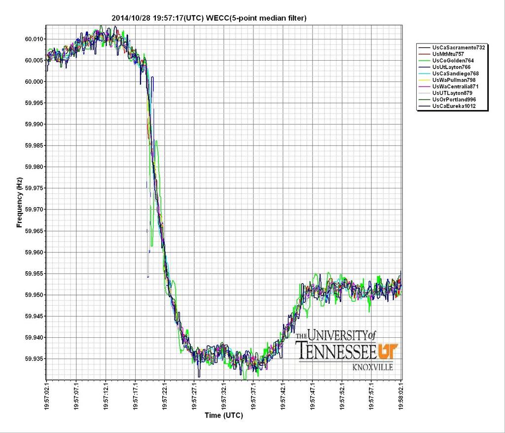
132 September 2011 Pacific Southwest Disturbance
133 September 8, 2011 A disturbance occurred on the afternoon of September 8, 2011 which led to cascading outages and loss of load. SDG&E, IID & CFE had complete system outages. APS and WALC lost some load.
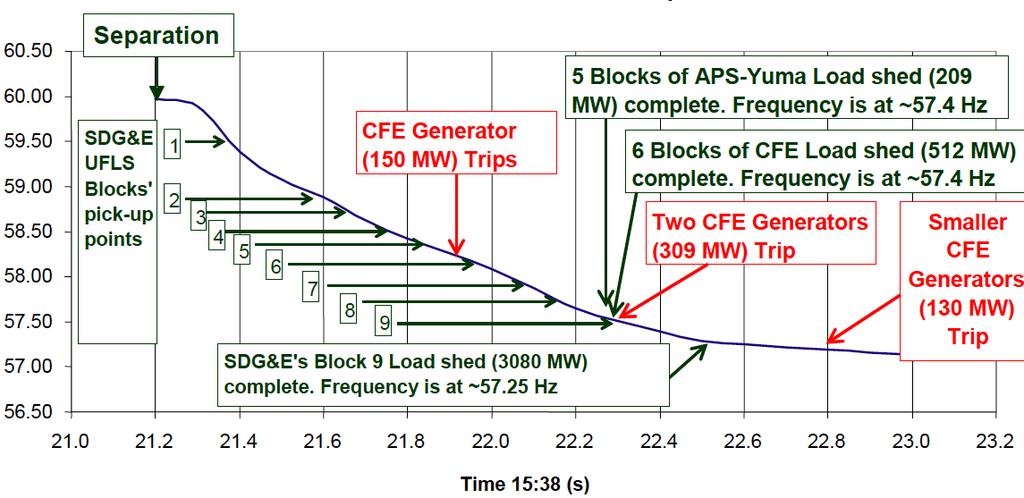
134 September 8, 2011 This disturbance occurred on a heavily loaded summer day. Load interrupted: SDG&E CFE IID APS WALC 4293 MW 2150 MW 929 MW 389 MW 74 MW
135 September 8, 2011 FERC / NERC Report findings: System was not being operated in a secure state for an N-1 outage due to: Lack of information sharing between entities. Lack of adequate studies. Sub 100 kv facilities not adequately considered in next-day studies. Initiating event: Loss of APS Hassayampa-North Gila 500 kv Line due to an operating error. All load was restored in approximately 12 hours.
136 Some NERC Standards Violated COM-002-2, R2 Issue directives in a clear & concise manner Three-part communication EOP b Developing, maintaining & implementing emergency plans EOP Shed load rather than risking uncontrolled failure or cascade EOP Returning system to normal following a disturbance EOP Coordination with Reliability Coordinator TOP Operate so that instability, uncontrolled separation, or cascading outages will not occur as a result of the most severe single contingency
137
138 Sequence of Events 1 At 1527, APS Hassayampa-North Gila 500 kv line relayed due to switchmen error. Loss of 500 kv line caused overload on area s lower voltage system as power sought alternate route into San Diego area. IID s 92 kv system started to collapse within 40 seconds of initial 500 kv line trip.
139 Sequence of Events 2 IID lost 230/92 kv transformers at Cochella Valley and Ramon. CFE lost generation in Mexico. IID experienced a voltage collapse in its service area and lost 50% of load when UVLS operated.
140
141 Sequence of Events - 3 As IID, WAPA and APS lower voltage system collapsed the 230 kv system on the coast loaded heavier and heavier. A protection scheme associated with path 44 operated separating the San Diego, IID, and CFE systems. Load was much greater than generation so system collapsed. UFLS operated but too little too late. Entire event took only 11 minutes.
142
143
144 Questions?

145 Things left to do???? REVIEW Collect Pre-test & Simulator Modules Complete course evaluation Take final exam

146 Closed Book! TEST TIME

147 You Endured to the End! Please turn in your Class evaluations and plastic badge holders.
148 Thank you!
Keeping it up to Speed Off-Nominal Frequency Operations. CETAC 2018 San Ramon
 Keeping it up to Speed Off-Nominal Frequency Operations CETAC 2018 San Ramon 1 Welcome CETAC 2018 San Ramon Valley Conference Center General Class Information: Safety/Fire evacuation In event of emergency,
Table 1 - Assignment of BA Obligations... 8
 Dynamic Transfer Reference Guidelines Version 2 June 2010 Table of Contents Table of Contents Chapter 1 Overview... 3 Purpose... 3 Terms... 3 Chapter 2 Dynamic Schedule Versus Pseudo-tie Fundamentals...
Wind Power Facility Technical Requirements CHANGE HISTORY
 CHANGE HISTORY DATE VERSION DETAIL CHANGED BY November 15, 2004 Page 2 of 24 TABLE OF CONTENTS LIST OF TABLES...5 LIST OF FIGURES...5 1.0 INTRODUCTION...6 1.1 Purpose of the Wind Power Facility Technical
ESB National Grid Transmission Planning Criteria
 ESB National Grid Transmission Planning Criteria 1 General Principles 1.1 Objective The specific function of transmission planning is to ensure the co-ordinated development of a reliable, efficient, and
DUKE ENERGY CAROLINAS TRANSMISSION SYSTEM PLANNING GUIDELINES. Transmission Planning
 DUKE ENERGY CAROLINAS TRANSMISSION SYSTEM PLANNING GUIDELINES Transmission Planning TABLE OF CONTENTS I. SCOPE 1 II. TRANSMISSION PLANNING OBJECTIVES 2 III. PLANNING ASSUMPTIONS 3 A. Load Levels 3 B. Generation
System Operating Limit Definition and Exceedance Clarification
 System Operating Limit Definition and Exceedance Clarification The NERC-defined term System Operating Limit (SOL) is used extensively in the NERC Reliability Standards; however, there is much confusion
Reliability Guideline: Generating Unit Operations During Complete Loss of Communications
 1 1 1 1 1 1 1 1 0 1 0 1 0 1 Reliability Guideline: Generating Unit Operations During Complete Loss of Communications Preamble: It is in the public interest for the North American Electric Reliability Corporation
Standard BAL-005-0b Automatic Generation Control
 A. Introduction 1. Title: Automatic Generation Control 2. Number: BAL-005-0b 3. Purpose: This standard establishes requirements for Balancing Authority Automatic Generation Control (AGC) necessary to calculate
ITC Holdings Planning Criteria Below 100 kv. Category: Planning. Eff. Date/Rev. # 12/09/
 ITC Holdings Planning Criteria Below 100 kv * Category: Planning Type: Policy Eff. Date/Rev. # 12/09/2015 000 Contents 1. Goal... 2 2. Steady State Voltage & Thermal Loading Criteria... 2 2.1. System Loading...
Reliability Guideline: Generating Unit Operations During Complete Loss of Communications
 1 1 1 1 1 1 1 1 0 1 0 1 0 1 Reliability Guideline: Generating Unit Operations During Complete Loss of Communications Preamble It is in the public interest for the North American Electric Reliability Corporation
Lecture 15 EMS Application II Automatic Generation Contol. Davood Babazadeh
 Lecture 15 EMS Application II Automatic Generation Contol Davood Babazadeh 2015-12-03 Outline Generation Control - Why - How AGC design - Area Control Error - Parameter Calculation 2 Course road map 3
Calculating and Using Reporting ACE in a Tie Line Bias Control Program
 Calculating and Using Reporting ACE in a Tie Line Bias Control Program Introduction: Tie Line Bias 1 (TLB) control has been used as the preferred control method in North America for 75 years. In the early
Standard BAL b Automatic Generation Control
 A. Introduction 1. Title: Automatic Generation Control 2. Number: BAL-005-0.2b 3. Purpose: This standard establishes requirements for Balancing Authority Automatic Generation Control (AGC) necessary to
Document C-29. Procedures for System Modeling: Data Requirements & Facility Ratings. January 5 th, 2016 TFSS Revisions Clean Open Process Posting
 Document C-29 Procedures for System Modeling: January 5 th, 2016 TFSS Revisions Clean Open Process Posting Prepared by the SS-37 Working Group on Base Case Development for the Task Force on System Studies.
System Protection and Control Subcommittee
 Power Plant and Transmission System Protection Coordination Volts Per Hertz (24), Undervoltage (27), Overvoltage (59), and Under/Overfrequency (81) Protection System Protection and Control Subcommittee
Central Hudson Gas & Electric Corporation. Transmission Planning Guidelines
 Central Hudson Gas & Electric Corporation Transmission Planning Guidelines Version 4.0 March 16, 2016 Version 3.0 March 16, 2009 Version 2.0 August 01, 1988 Version 1.0 June 26, 1967 Table of Contents
NPCC Regional Reliability Reference Directory # 12. Underfrequency Load Shedding Program Requirements
 NPCC Regional Reliability Reference Directory # 12 Under frequency Load Shedding Program Requirements Task Force on System Studies Revision Review Record: June 26 th, 2009 March 3 rd, 2010 Adopted by the
Standard BAL b Automatic Generation Control
 A. Introduction 1. Title: Automatic Generation Control 2. Number: BAL-005-0.2b 3. Purpose: This standard establishes requirements for Balancing Authority Automatic Generation Control (AGC) necessary to
EE 742 Chapter 9: Frequency Stability and Control. Fall 2011
 EE 742 Chapter 9: Frequency Stability and Control Fall 2011 Meeting demand with generation Large and slow changes (24 hr) in power demand are met by unit commitment Medium and relatively fast changes (30
Implementation Plan Project Balancing Authority Reliability-based Controls - Reserves
 Implementation Plan Project 2010-14.1 Balancing Authority Reliability-based Controls - Reserves Implementation Plan for Approvals Required Prerequisite Approvals None Revisions to Glossary Terms The following
1
 Guidelines and Technical Basis Introduction The document, Power Plant and Transmission System Protection Coordination, published by the NERC System Protection and Control Subcommittee (SPCS) provides extensive
Reliability Guideline Integrating Reporting ACE with the NERC Reliability Standards
 Reliability Guideline Integrating Reporting ACE with the NERC Reliability Standards Applicability: Balancing Authorities (BAs) Introduction and Purpose: It is in the public interest for NERC to develop
PRC Generator Relay Loadability. Guidelines and Technical Basis Draft 5: (August 2, 2013) Page 1 of 76
 Page 1 of 76") PRC-025-1 Introduction The document, Power Plant and Transmission System Protection Coordination, published by the NERC System Protection and Control Subcommittee (SPCS) provides extensive general discussion
PRC-025-1 Introduction The document, Power Plant and Transmission System Protection Coordination, published by the NERC System Protection and Control Subcommittee (SPCS) provides extensive general discussion
Recently, the SS38 Working Group on Inter-Area Dynamic Analysis completed two study reports on behalf of the UFLS Regional Standard Drafting Team.
 December 7 th, 2010 NPCC Full Member Committee; Please find attached a draft revised NPCC Regional Reliability Directory #12 Underfrequency Load Shedding Program Requirements and a draft revised NPCC UFLS
ISO Rules Part 500 Facilities Division 502 Technical Requirements Section Wind Aggregated Generating Facilities Technical Requirements
 Applicability 1(1) Section 502.1 applies to the ISO, and subject to the provisions of subsections 1(2), (3) and (4) to any: (a) a new wind aggregated generating facility to be connected to the transmission
Standard BAL b3 Automatic GenerationBalancing Authority Control DRAFT
 A. Introduction 1. Title: Balancing Authority ControlAutomatic Generation Control 2. Number: BAL-005-30.2b 3. Purpose: This standard establishes requirements for acquiring necessary data for the Balancing
EH2741 Communication and Control in Electric Power Systems Lecture 2
 KTH ROYAL INSTITUTE OF TECHNOLOGY EH2741 Communication and Control in Electric Power Systems Lecture 2 Lars Nordström larsno@kth.se Course map Outline Transmission Grids vs Distribution grids Primary Equipment
NERC Protection Coordination Webinar Series June 23, Phil Tatro
 Power Plant and Transmission System Protection Coordination Volts Per Hertz (24), Undervoltage (27), Overvoltage (59), and Under/Overfrequency (81) Protection NERC Protection Coordination Webinar Series
PRC Generator Relay Loadability. Guidelines and Technical Basis Draft 4: (June 10, 2013) Page 1 of 75
 Page 1 of 75") PRC-025-1 Introduction The document, Power Plant and Transmission System Protection Coordination, published by the NERC System Protection and Control Subcommittee (SPCS) provides extensive general discussion
PRC-025-1 Introduction The document, Power Plant and Transmission System Protection Coordination, published by the NERC System Protection and Control Subcommittee (SPCS) provides extensive general discussion
ISO Rules Part 500 Facilities Division 502 Technical Requirements Section Aggregated Generating Facilities Technical Requirements
 Division 502 Technical Applicability 1(1) Section 502.1 applies to: Expedited Filing Draft August 22, 2017 the legal owner of an aggregated generating facility directly connected to the transmission system
Table of Contents Error! Bookmark not defined.
 Table of Contents Table of Contents... 1 Introduction... 2 Background... 2 Rationale by Requirement... 204 Requirement 1... 204 Background and Rationale... 204 Requirement 2... 268 Background and Rationale...
BED INTERCONNECTION TECHNICAL REQUIREMENTS
 BED INTERCONNECTION TECHNICAL REQUIREMENTS By Enis Šehović, P.E. 2/11/2016 Revised 5/19/2016 A. TABLE OF CONTENTS B. Interconnection Processes... 2 1. Vermont Public Service Board (PSB) Rule 5.500... 2
Power Plant and Transmission System Protection Coordination Fundamentals
 Power Plant and Transmission System Protection Coordination Fundamentals NERC Protection Coordination Webinar Series June 2, 2010 Jon Gardell Agenda 2 Objective Introduction to Protection Generator and
COMPARATIVE PERFORMANCE OF SMART WIRES SMARTVALVE WITH EHV SERIES CAPACITOR: IMPLICATIONS FOR SUB-SYNCHRONOUS RESONANCE (SSR)
") 7 February 2018 RM Zavadil COMPARATIVE PERFORMANCE OF SMART WIRES SMARTVALVE WITH EHV SERIES CAPACITOR: IMPLICATIONS FOR SUB-SYNCHRONOUS RESONANCE (SSR) Brief Overview of Sub-Synchronous Resonance Series
7 February 2018 RM Zavadil COMPARATIVE PERFORMANCE OF SMART WIRES SMARTVALVE WITH EHV SERIES CAPACITOR: IMPLICATIONS FOR SUB-SYNCHRONOUS RESONANCE (SSR) Brief Overview of Sub-Synchronous Resonance Series
GridLiance Reliability Criteria
 GridLiance Reliability Criteria Planning Department March 1, 2018 FOREWORD The GridLiance system is planned, designed, constructed, and operated to assure continuity of service during system disturbances
Frequency Response Characteristic Survey Training Document
 Frequency Response Characteristic Survey Training Document Training Document Subsections Frequency Response Characteristic Response to Internal and External Generation/Load Imbalances Frequency Bias versus
Standard Development Timeline
 Standard Development Timeline This section is maintained by the drafting team during the development of the standard and will be removed when the standard is adopted by the Board of Trustees. Description
TTC Study for: the PEGS-Ambrosia Lake 230 kv Line and the PEGS-Bluewater 115 kv Line
 TTC Study for: the PEGS-Ambrosia Lake 230 kv Line and the PEGS-Bluewater 115 kv Line Vince Leung March 27, 2017 Reviewed by Johnny Nguyen Table of Contents Background 2 Objective 3 Base Case Assumptions
each time the Frequency is above 51Hz. Continuous operation is required
 GC0101 EXTRACT OF EUROPEAN CONNECTION CONDITIONS LEGAL TEXT DATED 08/01/2018. ECC.6 ECC.6.1 ECC.6.1.1 ECC.6.1.2 ECC.6.1.2.1 ECC.6.1.2.1.1 ECC.6.1.2.1.2 ECC.6.1.2.1.3 TECHNICAL, DESIGN AND OPERATIONAL CRITERIA
Canadian Technology Accreditation Criteria (CTAC) POWER SYSTEMS ENGINEERING TECHNOLOGY - TECHNICIAN Technology Accreditation Canada (TAC)
 POWER SYSTEMS ENGINEERING TECHNOLOGY - TECHNICIAN Technology Accreditation Canada (TAC)") Canadian Technology Accreditation Criteria (CTAC) POWER SYSTEMS ENGINEERING TECHNOLOGY - TECHNICIAN Technology Accreditation Canada (TAC) Preamble These CTAC are applicable to programs having titles involving
Canadian Technology Accreditation Criteria (CTAC) POWER SYSTEMS ENGINEERING TECHNOLOGY - TECHNICIAN Technology Accreditation Canada (TAC) Preamble These CTAC are applicable to programs having titles involving
Industry Webinar. Reactive Power Planning. NERC System Analysis and Modeling Subcommittee (SAMS) March 2017
 March 2017") Industry Webinar Reactive Power Planning NERC System Analysis and Modeling Subcommittee (SAMS) March 2017 Webinar Topics Reliability Guideline on Reactive Power Planning Webinar Topics Fundamentals of
Industry Webinar Reactive Power Planning NERC System Analysis and Modeling Subcommittee (SAMS) March 2017 Webinar Topics Reliability Guideline on Reactive Power Planning Webinar Topics Fundamentals of
NVESTIGATIONS OF RECENT BLACK-
 DIGITAL VISION outs indicate that the root cause of almost all major power system disturbances is voltage collapse rather than the underfrequency conditions prevalent in the blackouts of the 1960s and
Generation and Load Interconnection Standard
 Generation and Load Interconnection Standard Rev. 0 DRAFT Name Signature Date Prepared: Approved: VP Acceptance APEGGA Permit to Practice P-08200 TABLE OF CONTENTS 1.0 INTRODUCTION...5 1.1 Purpose...5
Real Time Stability Analysis at Peak Reliability. Slaven Kincic, Hongming Zhang JSIS May 2017, SLC
 Real Time Stability Analysis at Peak Reliability Slaven Kincic, Hongming Zhang JSIS May 2017, SLC Overview: Overview of Peak s DSA Application; o Set up o User Cases Transient Stability Criteria; TSAT
EE 742 Power System Components. Y. Baghzouz ECE Department UNLV
 EE 742 Power System Components Y. Baghzouz ECE Department UNLV Desire to have a system with high reliability and power quality High reliability ensured by High quality of components High level of system
NERC Protection Coordination Webinar Series June 16, Phil Tatro Jon Gardell
 Power Plant and Transmission System Protection Coordination Phase Distance (21) and Voltage-Controlled or Voltage-Restrained Overcurrent Protection (51V) NERC Protection Coordination Webinar Series June
Generation and Load Interconnection Standard
 Generation and Load Interconnection Standard Rev. 0A DRAFT Name Signature Date Prepared: Approved: VP Acceptance APEGGA Permit to Practice P-08200 TABLE OF CONTENTS 1.0 INTRODUCTION...5 1.1 Purpose...5
TECHNICAL SPECIFICATIONS AND OPERATING PROTOCOLS AND PROCEDURES FOR INTERCONNECTION OF LARGE GENERATION FACILITIES. Document 9020
 TECHNICAL SPECIFICATIONS AND OPERATING PROTOCOLS AND PROCEDURES FOR INTERCONNECTION OF LARGE GENERATION FACILITIES Document 9020 Puget Sound Energy, Inc. PSE-TC-160.50 December 19, 2016 TABLE OF CONTENTS
(Circuits Subject to Requirements R1 R5) Generator Owner with load-responsive phase protection systems as described in
 Generator Owner with load-responsive phase protection systems as described in") A. Introduction 1. Title: Transmission Relay Loadability 2. Number: PRC-023-3 3. Purpose: Protective relay settings shall not limit transmission loadability; not interfere with system operators ability
A. Introduction 1. Title: Transmission Relay Loadability 2. Number: PRC-023-3 3. Purpose: Protective relay settings shall not limit transmission loadability; not interfere with system operators ability
Texas Reliability Entity Event Analysis. Event: May 8, 2011 Loss of Multiple Elements Category 1a Event
 Texas Reliability Entity Event Analysis Event: May 8, 2011 Loss of Multiple Elements Category 1a Event Texas Reliability Entity July 2011 Page 1 of 10 Table of Contents Executive Summary... 3 I. Event
ISO Rules Part 500 Facilities Division 502 Technical Requirements Section SCADA Technical and Operating Requirements
 Section 502.8 SCADA Technical and Operating Applicability 1 Section 502.8 applies to: (a) the legal owner of a generating unit: (i) connected to the transmission facilities in the balancing authority area
Procedure for ERO Support of Frequency Response and Frequency Bias Setting Standard. Event Selection Process
 This procedure outlines the Electric Reliability Organization (ERO) process for supporting the Frequency Response Standard (FRS). A Procedure revision request may be submitted to the ERO for consideration.
HOOSIER ENERGY REC, INC. Requirements for Connection of Generation Facilities. to the HE Transmission System
 HOOSIER ENERGY REC, INC Requirements for Connection of Generation Facilities to the HE Transmission System January 2009 Table of Contents 1.0 INTRODUCTION...1 2.0 TYPES OF CONNECTED CIRCUIT CONFIGURATIONS...6
Phase Angle Monitoring:
 Phase Angle Monitoring: Industry Experience Following the 2011 Pacific Southwest Outage Recommendation 27 Ryan D. Quint, PhD, PE NERC SMS Coordinator NASPI Work Group Meeting October 2016 Background Purpose:
SYNCHROPHASOR TECHNOLOGY GLOSSARY Revision Date: April 24, 2011
 SYNCHROPHASOR TECHNOLOGY GLOSSARY Revision Date: April 24, 2011 Baselining using large quantities of historical phasor data to identify and understand patterns in interconnection-wide grid behavior, to
Standard Development Timeline
 Standard Development Timeline This section is maintained by the drafting team during the development of the standard and will be removed when the standard becomes effective. Description of Current Draft
Frequency Response Standard Background Document November, 2012
 Frequency Response Standard Background Document November, 2012 3353 Peachtree Road NE Suite 600, North Tower Atlanta, GA 30326 404-446-2560 www.nerc.com Table of Contents Table of Contents... 1 Introduction...
PRC Generator Relay Loadability. A. Introduction 1. Title: Generator Relay Loadability 2. Number: PRC-025-1
 PRC-025-1 Generator Relay Loadability A. Introduction 1. Title: Generator Relay Loadability 2. Number: PRC-025-1 Purpose: To set load-responsive protective relays associated with generation Facilities
Table of Contents. Introduction... 1
 Table of Contents Introduction... 1 1 Connection Impact Assessment Initial Review... 2 1.1 Facility Design Overview... 2 1.1.1 Single Line Diagram ( SLD )... 2 1.1.2 Point of Disconnection - Safety...
Application for A Sub-harmonic Protection Relay. ERLPhase Power Technologies
 Application for A Sub-harmonic Protection Relay ERLPhase Power Technologies 1 Outline Introduction System Event at Xcel Energy Event Analysis Microprocessor based relay hardware architecture Sub harmonic
Brianna Swenson Alliant Energy Minnesota Power Systems Conference November 8, 2017
 Brianna Swenson Alliant Energy Minnesota Power Systems Conference November 8, 2017 Topics Brief history of interties and regulations Who is involved? What exactly are we doing? Why is it important? Project
Harmonizing the Changing Resource Mix Keeping the Grid Together
 Harmonizing the Changing Resource Mix Keeping the Grid Together Robert W. Cummings Senior Director of Engineering and Reliability Initiatives i-pcgrid March 30, 2017 NERC-IEEE Memorandum of Understanding
FACILITY CONNECTION REQUIREMENTS
 Portland General Electric Facility Connection Requirements - Generation Resources FACILITY CONNECTION REQUIREMENTS FOR GENERATION RESOURCES PORTLAND GENERAL ELECTRIC PORTLAND, OREGON JULY 12, 2013 REVISION
Power Plant and Transmission System Protection Coordination of-field (40) and Out-of. of-step Protection (78)
 and Out-of. of-step Protection (78)") Power Plant and Transmission System Protection Coordination Loss-of of-field (40) and Out-of of-step Protection (78) System Protection and Control Subcommittee Protection Coordination Workshop Phoenix,
Power Plant and Transmission System Protection Coordination Loss-of of-field (40) and Out-of of-step Protection (78) System Protection and Control Subcommittee Protection Coordination Workshop Phoenix,
Generation Interconnection Requirements at Voltages 34.5 kv and Below
 Generation Interconnection Requirements at Voltages 34.5 kv and Below 2005 March GENERATION INTERCONNECTION REQUIREMENTS AT 34.5 KV AND BELOW PAGE 1 OF 36 TABLE OF CONTENTS 1. INTRODUCTION 5 1.1. Intent
IDAHO PURPA GENERATOR INTERCONNECTION REQUEST (Application Form)
") IDAHO PURPA GENERATOR INTERCONNECTION REQUEST (Application Form) Transmission Provider: IDAHO POWER COMPANY Designated Contact Person: Jeremiah Creason Address: 1221 W. Idaho Street, Boise ID 83702 Telephone
IDAHO PURPA GENERATOR INTERCONNECTION REQUEST (Application Form) Transmission Provider: IDAHO POWER COMPANY Designated Contact Person: Jeremiah Creason Address: 1221 W. Idaho Street, Boise ID 83702 Telephone
UNIT-II REAL POWER FREQUENCY CONTROL. 1. What is the major control loops used in large generators?
 UNIT-II REAL POWER FREQUENCY CONTROL 1. What is the major control loops used in large generators? The major control loops used in large generators are Automatic voltage regulator (AVR) Automatic load frequency
VOLTAGE STABILITY OF THE NORDIC TEST SYSTEM
 1 VOLTAGE STABILITY OF THE NORDIC TEST SYSTEM Thierry Van Cutsem Department of Electrical and Computer Engineering University of Liège, Belgium Modified version of a presentation at the IEEE PES General
Use of the Power System Outlook (PSO) and SMART 1 Programs to View PSLF Dynamic Simulation Data Files
 and SMART 1 Programs to View PSLF Dynamic Simulation Data Files") 21, rue d Artois, F-75008 PARIS CIGRE US National Committee http : //www.cigre.org 2014 Grid of the Future Symposium Use of the Power System Outlook (PSO) and SMART 1 Programs to View PSLF Dynamic Simulation
21, rue d Artois, F-75008 PARIS CIGRE US National Committee http : //www.cigre.org 2014 Grid of the Future Symposium Use of the Power System Outlook (PSO) and SMART 1 Programs to View PSLF Dynamic Simulation
Northeast Power Coordinating Council, Inc. Glossary of Terms. Approved by the Reliability Standards Committee
 Northeast Power Coordinating Council, Inc. Glossary of Terms Approved by the Reliability Standards Committee October 26, 2011 Revision History Version Date Action Change Tracking (New, Errata or Revisions)
Grid Code Review Panel. Information Required to Evaluate Subsynchrononous Resonance on the Transmission System
 Grid Code Review Panel Information Required to Evaluate Subsynchrononous Resonance on the Transmission System Summary of Issue A paper by National Grid Contact: Graham Stein 1. All electrical and electromechanical
Voltage and Reactive Procedures CMP-VAR-01
 Voltage and Reactive Procedures CMP-VAR-01 NERC Standards: VAR-001-2 VAR-002-1.1b Effective Date: 07/31/2012 Document Information Current Revision 2.0 Review Cycle Annual Subject to External Audit? Yes
Endorsed Assignments from ERS Framework
 ERSTF Completion Endorsed Assignments from ERS Framework Ref Number Title ERS Recommendatio n Ongoing Responsibility 1 Synch Inertia at Interconnection Level Measure 2 Initial Frequency Deviation Measure
ISO Rules Part 500 Facilities Division 502 Technical Requirements Section SCADA Technical and Operating Requirements
 Section 502.8 SCADA Technical and Operating Requirements Applicability 1 Subject to subsections 2 and 3 below, section 502.8 applies to: (a) (c) (d) the legal owner of a generating unit or an aggregated
NERC / TVA STABILITY WORKSHOP
 NERC / TVA STABILITY WORKSHOP CHATTANOOGA, TN MAY 23-24, 24, 2007 Robert Dintelman Utility System Efficiencies, Inc. WECC Transmission System 1996 Western Outages July 2, 1996 July 3, 1996 August 10, 1996
ROSE - Real Time Analysis Tool for Enhanced Situational Awareness
 ROSE - Real Time Analysis Tool for Enhanced Situational Awareness Marianna Vaiman V&R Energy Copyright 1997-2013 V&R Energy Systems Research, Inc. All rights reserved. WECC JSIS Salt Lake City, UT October
CAISO Restricted - Do Not Distribute Outside of RC Project LOI and NDA Entities Page 1 of 24
 RC0120A - RC IRO-010 Data Specification NOTE: Changes from Peak's Attachment A are highlighted in red in columns C through G Section Category Number Responsible Pa Data Item Data Transfer Method 1.1 Transmission
NERC Protection Coordination Webinar Series June 30, Dr. Murty V.V.S. Yalla
 Power Plant and Transmission System Protection ti Coordination Loss-of-Field (40) and Out-of of-step Protection (78) NERC Protection Coordination Webinar Series June 30, 2010 Dr. Murty V.V.S. Yalla Disclaimer
E N G I N E E R I N G M A N U A L
 1 1 1.0 PURPOSE The purpose of this document is to define policy and provide engineering guidelines for the AP operating companies (Monongahela Power Company, The Potomac Edison Company, and West Penn
PJM Manual 07:: PJM Protection Standards Revision: 2 Effective Date: July 1, 2016
 PJM Manual 07:: PJM Protection Standards Revision: 2 Effective Date: July 1, 2016 Prepared by System Planning Division Transmission Planning Department PJM 2016 Table of Contents Table of Contents Approval...6
OPERATING, METERING AND EQUIPMENT PROTECTION REQUIREMENTS FOR PARALLEL OPERATION OF LARGE-SIZE GENERATING FACILITIES GREATER THAN 25,000 KILOWATTS
 OPERATING, METERING AND EQUIPMENT PROTECTION REQUIREMENTS FOR PARALLEL OPERATION OF LARGE-SIZE GENERATING FACILITIES GREATER THAN 25,000 KILOWATTS AND MEDIUM-SIZE FACILITIES (5,000-25,000KW) CONNECTED
NORMES DE FIABILITÉ DE LA NERC (VERSION ANGLAISE)
") COORDONNATEUR DE LA FIABILITÉ Direction Contrôle des mouvements d énergie Demande R-3944-2015 NORMES DE FIABILITÉ DE LA NERC (VERSION ANGLAISE) Original : 2016-10-14 HQCMÉ-10, Document 2 (En liasse) Standard
COORDONNATEUR DE LA FIABILITÉ Direction Contrôle des mouvements d énergie Demande R-3944-2015 NORMES DE FIABILITÉ DE LA NERC (VERSION ANGLAISE) Original : 2016-10-14 HQCMÉ-10, Document 2 (En liasse) Standard
Technical Interconnection Requirements For Transmission Voltage Customers for Service at 60,000 to 287,000 Volts R XX
 Technical Interconnection Requirements For Transmission Voltage Customers for Service at 60,000 to 287,000 Volts R XX May 2018 Disclaimer This document provides general technical interconnection requirements
Arizona Public Service Company and the Transmission Partnership for National Electric Power Company of Jordan
 Arizona Public Service Company and the Transmission Partnership for National Electric Power Company of Jordan Mark Hackney October 5-8, 2009 Amman, Jordan Energy Control Center Layout 2 Energy Control
Southern Company Interconnection Requirements for Inverter-Based Generation
 Southern Company Interconnection Requirements for Inverter-Based Generation September 19, 2016 Page 1 of 16 All inverter-based generation connected to Southern Companies transmission system (Point of Interconnection
System Protection and Control Subcommittee
 Power Plant and Transmission System Protection Coordination Reverse Power (32), Negative Sequence Current (46), Inadvertent Energizing (50/27), Stator Ground Fault (59GN/27TH), Generator Differential (87G),
Transmission Interconnection Requirements for Inverter-Based Generation
 Transmission Requirements for Inverter-Based Generation June 25, 2018 Page 1 Overview: Every generator interconnecting to the transmission system must adhere to all applicable Federal and State jurisdictional
TECHNICAL SPECIFICATIONS AND OPERATING PROTOCOLS AND PROCEDURES FOR INTERCONNECTION OF GENERATION FACILITIES NOT SUBJECT TO FERC JURISDICTION
 TECHNICAL SPECIFICATIONS AND OPERATING PROTOCOLS AND PROCEDURES FOR INTERCONNECTION OF GENERATION FACILITIES NOT SUBJECT TO FERC JURISDICTION Document 9022 Puget Sound Energy, Inc. PSE-TC-160.70 December
MANITOBA HYDRO TRANSMISSION SYSTEM INTERCONNECTION REQUIREMENTS. April 2009 Version 2
 MANITOBA HYDRO TRANSMISSION SYSTEM INTERCONNECTION REQUIREMENTS April 2009 Version 2 LEGISLATIVE AUTHORITY Section 15(5) of The Manitoba Hydro Act authorizes Manitoba Hydro to set, coordinate and enforce
TECHNICAL SPECIFICATIONS AND OPERATING PROTOCOLS AND PROCEDURES FOR SMALL GENERATION INTERCONNECTIONS
 TECHNICAL SPECIFICATIONS AND OPERATING PROTOCOLS AND PROCEDURES FOR SMALL GENERATION INTERCONNECTIONS Puget Sound Energy, Inc. PSE-ET-160.60 October 30, 2007 TABLE OF CONTENTS 1. INTRODUCTION...1 1.1 GENERAL
PRC Generator Relay Loadability. A. Introduction 1. Title: Generator Relay Loadability 2. Number: PRC-025-1
 A. Introduction 1. Title: Generator Relay Loadability 2. Number: PRC-025-1 Purpose: To set load-responsive protective relays associated with generation Facilities at a level to prevent unnecessary tripping
Using Synchrophasors for Frequency Response Analysis in the Western Interconnection. Bonneville Power Administration -- WECC JSIS Chair
 21, rue d Artois, F-75008 PARIS CIGRE US National Committee http : //www.cigre.org 2014 Grid of the Future Symposium Using Synchrophasors for Frequency Response Analysis in the Western Interconnection
Issued: September 2, 2014 Effective: October 3, 2014 WN U-60 Attachment C to Schedule 152, Page 1 PUGET SOUND ENERGY
 WN U-60 Attachment C to Schedule 152, Page 1 SCHEDULE 152 APPLICATION FOR INTERCONNECTING A GENERATING FACILITY TIER 2 OR TIER 3 This Application is considered complete when it provides all applicable
Massive Transient Stability Based Cascading Analysis and On-line Identification of Critical Cascades
 1 Massive Transient Stability Based Cascading Analysis and On-line Identification of Critical Cascades Paper Number: 16PESGM2419 Marianna Vaiman, V&R Energy marvaiman@vrenergy.com 2016 IEEE PES General
Transmission System Phase Backup Protection
 Reliability Guideline Transmission System Phase Backup Protection NERC System Protection and Control Subcommittee Draft for Planning Committee Approval June 2011 Table of Contents 1. Introduction and Need
Unit Auxiliary Transformer Overcurrent Relay Loadability During a Transmission Depressed Voltage Condition
 Unit Auxiliary Transformer Overcurrent Relay Loadability During a Transmission Depressed Voltage Condition NERC System Protection and Control Subcommittee March 2016 NERC Report Title Report Date I Table
Grid codes and wind farm interconnections CNY Engineering Expo. Syracuse, NY November 13, 2017
 Grid codes and wind farm interconnections CNY Engineering Expo Syracuse, NY November 13, 2017 Purposes of grid codes Grid codes are designed to ensure stable operating conditions and to coordinate the
Standard PRC Generator Frequency and Voltage Protective Relay Settings. A. Introduction
 A. Introduction 1. Title: Generator Frequency and Voltage Protective Relay Settings 2. Number: PRC-024-1 3. Purpose: Ensure Generator Owners set their generator protective relays such that generating units
NERC Training Document Understand and Calculate Frequency Response
 N E R C Assisting System Personnel In Keeping Current NERC Training Document Understand and Calculate Frequency Response Developed by: NERC Training Resources Working Group February 20, 2003 Subject: Understand
Final ballot January BOT adoption February 2015
 Standard PRC-024-21(X) Generator Frequency and Voltage Protective Relay Settings Standard Development Timeline This section is maintained by the drafting team during the development of the standard and