HOOSIER ENERGY REC, INC. Requirements for Connection of Generation Facilities. to the HE Transmission System
|
|
|
- Cornelius Lucas
- 5 years ago
- Views:
Transcription
1 HOOSIER ENERGY REC, INC Requirements for Connection of Generation Facilities to the HE Transmission System January 2009
2 Table of Contents 1.0 INTRODUCTION TYPES OF CONNECTED CIRCUIT CONFIGURATIONS DESIGN REQUIREMENTS FOR CONNECTION REQUIREMENTS FOR OPERATION PROTECTIVE RELAYING TESTING AND MAINTENANCE METERING AND TELEMETRY COMMUNICATIONS COSTS INCURRED DESIGN REVIEW INSPECTION REQUIREMENTS FINAL DOCUMENTATION APPROVAL SPECIAL PROVISIONS COORDINATION WITH OTHER CODES, STANDARDS, AND AGENCIES INDEMNIFICATION...22 APPENDIX A:...23 Figures...23 APPENDIX B:...26 Generation Dynamic Performance Data...26 APPENDIX C:...29 HE Voltage Flicker Criteria and Harmonic Distortion Criteria...29 APPENDIX D:...36 Generation Abnormal Frequency Operating Allowance...36 APPENDIX E:...38 Notification of Intent to Install and Operate Generation Interconnected with the HE Transmission System...38 ii
3 1.0 INTRODUCTION Hoosier Energy REC, Inc., has prepared this document which outlines the minimum requirements for all generation facilities connecting to the HE Transmission System, or to transmission owned by others connected to and operated in the HE control area. 1.1 Background In the present electric utility environment characterized by deregulation, open access to the transmission network, wholesale and retail competition, etc., there is wide recognition that electric system reliability, safety and quality of service are to be maintained. Maintaining reliability, safety and quality of service in this changing environment places additional challenges in the planning and operation of electric systems. As a result of this new environment, there are an increasing number of requests to connect to and use the HE Transmission System. Each request is reviewed to identify the facility impacts and necessary system improvements on the HE system. These reviews ensure that comparable treatment is given to all users, and that reliability, safety, and quality of service are maintained. The Hoosier Energy transmission system is, in effect, managed by the Midwest Independent System Operator (MISO). Any requests to connect generation to the Hoosier Energy system must be submitted to and approved by MISO, per MISO procedures. 1.2 Scope This document informs entities seeking facility connections to the HE Transmission System of the generation connection requirements. The requirements are applicable to all facilities connecting to the HE Transmission System, both those owned by HE as well as facilities owned by other parties. The scope of this document satisfies the NERC Planning Standards by identifying requirements for connections to the bulk transmission system at voltages generally 100 kv and above. This document also applies to connections to those systems designated as transmission facilities that are rated at lower voltages, which include 69 and 34.5kV. Requirements applicable for all types of generation facilities, regardless of generation capacity, are covered. 1
4 The minimum requirements pertaining to connected facilities are contained herein. Reliability concerns in particular are such that additional requirements may need to be imposed on connecting facilities based on their location within the system, facility power level and the associated impacts on HE s system performance. The need for additional requirements can only be evaluated once certain details of a proposed facility are made known and system impact studies have been conducted. The requirements for initial facility connection apply equally to continued operation of existing connected facilities. Therefore, any upgrades, additions, enhancements, or changes of any kind to an existing connected facility are subject to HE review to ensure continued compliance with these requirements. The scope of these documents is limited to the technical requirements for connected facility design and operation. Generation Facility Owners interested in the terms of transmission service should refer appropriate Midwest ISO Tariff documents. 1.3 Objectives HE, in its role as a transmission provider, has prepared this document based on the following objectives: a) Maintain system reliability, personnel and equipment safety, and quality of service as new facilities are added to the transmission network and existing facilities are modified. b) Ensure comparability in the requirements imposed upon the various entities seeking to connect facilities to the transmission network. c) Satisfy compliance with NERC Standards FAC-001 and FAC-002 pertaining to documentation of facility connection requirements by those entities responsible for system reliability. d) Inform those entities that seek facility connections to the HE Transmission System of the various requirements for system reliability, safety of personnel and equipment, and quality of service. e) Facilitate uniform and compatible equipment specification, design, engineering, and installation practices to promote safety and uniformity of service. 1.4 Request for Interconnection to MISO Under current MISO rules, and organization seeking to connect to the Hoosier Energy must request approval from MISO first. This involves submitting the appropriate information to the MISO generation queue for approval. The procedures for applying for MISO 2
5 approval are documented at the MISO website. This policy assumes the proposing entity has requested MISO approval 1.5 Rough Plan of Service Following MISO approval, the entity proposing the interconnection, with approval of Hoosier Energy, will facilitate a system impact study (discussed in the following step by preparing a rough plan of service to provide information on proposed transformer and line loading and other high level information needed for the system impact study. This rough plan will be used later for the detailed plan, upon approval of the project by MISO following analysis of system impact. 1.6 System Impact Studies In order to assess the impact of a proposed facility connection on system reliability, system impact studies need to be conducted. These system impact studies, as a minimum, examine the transmission line and transformer loading; voltage profiles and schedules; minimum reactive requirements; and power quality impacts of the proposed facility for a range of expected seasonal loading and power transfer conditions. The effect of the proposed facility on short circuit duties is examined for all proposed generation facilities and transmission connections. Stability performance is also assessed for all proposed generation facilities. A multi-step approach to the proposed facility may be considered where the impact of each step is assessed separately. Alternative plans of service may be considered. All requesters of generation connection service must petition Midwest Independent System Operator (MISO) for approval of the connection. MISO then performs any system impact studies needed for the interconnections at the owner s cost. All generation connections above 100kV and selected interconnections (at MISO discretion) at 69kV will be evaluated by MISO. See MISO Procedures for details Power Flow Analyses Power flow analyses are conducted to examine the impact of the proposed facility on nearby transmission line and transformer loading, and nearby voltage profiles. These analyses may typically determine the maximum generation that can be accommodated with minimal or no upgrades to the transmission system. Contingencies consisting of single or multiple outages of lines and/or transformers are considered in these analyses. Where the analyses indicate that transmission upgrades are necessary, alternative reinforcement plans may be devised and evaluated for their capability to accommodate the proposed facility. These analyses may also indicate a need to perform dynamic studies. 3
6 1.6.2 Short Circuit Analyses Short circuit analyses are conducted to examine the impact of the proposed facility on equipment duties. Increased fault duties may require upgrading existing circuit breakers and other equipment Transient Stability Studies The ability of a proposed generation facility to remain in synchronism with the transmission network during disturbances, including faults, is investigated here. As with load flow analyses, transient stability studies determine how much generation can be accommodated at a given location. Typically, disturbances corresponding to the contingencies examined in the load flow analyses are simulated. Other aspects of system dynamic performance affected by the proposed generation facility may be assessed. Any required remedial measures, transmission facility upgrades and/or additional design requirements for the proposed generation facility are identified. The criteria HE uses to determine what constitutes acceptable performance in the above system impact studies is readily available from HE s FERC Form 715 filing Additional Analyses Other analyses may be required as part of system impact studies depending on the nature of the proposed connected facility and its location within the transmission network. Power quality analyses are undertaken for all generation that could potentially cause harmonic current or voltage, voltage flicker, and/or telephone interference. Criteria for harmonic interference, voltage flicker, and telephone interference are included in the document appendices. The scope of all the above system impact studies is determined by MISO based on the type, location, and power level of the proposed facility. Normally, MISO will perform the system impact studies at the expense of the Owner. 1 A report documenting the assumptions, results, and conclusions of the system impact studies is made available to the Generation Facility Owner. HE and MISO must be notified of new facilities, upgrades, or additions such as an increase in load or added generating units to existing facilities connected to the transmission system within the HE Control Area. System impact studies are to be conducted to determine the need for any upgrades of transmission equipment or transmission reinforcements to the HE system to accommodate the changes in the connected facility. 1.7 Facility Connection Study A facility connection study is performed to evaluate and determine the physical connection between the transmission system and a proposed connected facility. The 1 Hereinafter the Owner refers to the Generation Facility Owner or third party acting on behalf of the Generation Facility Owner. 4
7 electrical configuration of the connection equipment including transformers, switchgear and other station equipment, and required transmission line sections are determined. Appendix A illustrates some of the more typical configurations for facility connections, but other possibilities exist depending on the particular situation. The physical layout of equipment and right-of-way needs are determined in the facility connection study as well. Typically, more than one alternative is considered in developing a facility connection depending upon the accessibility of the local area transmission facilities and the needs of the proposed connected facility. A multi-step approach may be considered in the facility connection study to accommodate a multistep increase in generation for the connected facility. Normally, the expense of developing a facility connection is the responsibility of the Generation Facility Owner. 1.8 Initiating a Facility Connection or Facility Change The following table outlines the HE personnel to be contacted with regard to any request for a new facility connection or significant change to an existing connected facility. As noted above, requests for new generation or a significant changes to existing generation must be approved by MISO before HE takes action Requests for transmission service to MISO should be made simultaneously with a connection request. The Generation Facility Owner is required to complete and forward a Notification of Intent to Install and Operate Generation (NIOG) to the HE contact with the appropriate deposit and all necessary attachments. See Section 10. The table below summarizes the interface needed with HE by the entities seeking to connect their generation facilities to the HE Transmission System. Type of Facility To be Connected Generation Service or Activity Required From HE Initial Contact to Request Connection or Studies HE Contact Manager Technical Assets Following the initial contact regarding a proposed generation facility connection, when the generator s proposed location and power level are established, a rough plan of service is prepared by HE and system impact studies are undertaken by MISO (in most cases) as needed. The information needed to develop a plan of service and to conduct the system impact studies should be provided to HE or MISO at this point. The system impact studies may, as noted above, identify additional requirements for reliability beyond the minimum requirements covered by this document. HE approval of a proposed facility or facility change is contingent upon a design review of the proposed connected facility. Operation of a connected facility is also subject to continuing compliance with all applicable construction, maintenance, testing, protection, monitoring, and documentation requirements described herein, as well as the applicable NERC Planning Standards and RFC documents noted herein. HE s facility connection requirements are organized into two separate documents titled Requirements for Connection of Non-Generation Facilities to the HE 5
8 Transmission System covering end-user and transmission interconnection facilities, and Requirements for Connection of Generation Facilities to the HE Transmission System for generation. This is because many requirements applicable to generation do not apply to Transmission End-User or Transmission Interconnection facilities. Likewise, requirements applicable to Transmission End-User facilities and Transmission Interconnections do not always pertain to generation. However, when a proposed facility includes both generation and Transmission End-User or Transmission Interconnection facilities, the proposing entities will need to consult both documents. 1.9 Responsibilities All Owners may be responsible for the costs associated with connecting to the HE Transmission System. This will include both the costs of the Owner s facilities and all costs of modifications and/or additions to HE transmission facilities required to integrate the generation facilities. HE will also require reimbursement for evaluation of requests for service, for performing necessary System Impact Studies, and for required regulatory filings. These direct costs may also be increased to cover any increase in taxes in those jurisdictions where applicable. The information contained herein is subject to change and may be revised at any time. 2.0 TYPES OF CONNECTED CIRCUIT CONFIGURATIONS The typical arrangement for generation connected to a transmission line is shown in Figure 1 of Appendix A, and the typical arrangement for generation connected to a breakered bus is shown in Figure 2 of Appendix A. These figures illustrate some acceptable configurations for connection of generation to the HE Transmission System. This document is not intended to cover the connection of generation to distribution systems. For requirements applicable to distribution connected generation, the Generation Facility Owner should contact local HE member cooperativess. 3.0 DESIGN REQUIREMENTS FOR CONNECTION The Generation Facility Owner is responsible for installing appropriate equipment and facilities so that the generation is compatible with the HE Transmission System. The Owner is also responsible for meeting any applicable federal, state, and local codes. The minimum HE Transmission System connection requirements for generation are as follows. 3.1 Generator Frequency The Owner s generating facility will provide a balanced, symmetrical, three phase interchange of electrical power with the HE Transmission System at a nominal frequency of 60 Hz. 3.2 System Protection The Generation Facility Owner is responsible for providing adequate protection to HE facilities for conditions arising from the operation of generation under all HE 6
9 transmission system operating conditions. The Owner is also responsible for providing adequate protection to their facility under any HE transmission system operating condition whether or not their generation is in operation. Conditions may include but are not limited to: 1. single phasing of supply, 2. transmission system faults, 3. equipment failures, 4. abnormal voltage or frequency, 5. lightning and switching surges, 6. excessive harmonic voltages, 7. excessive negative sequence voltages, 8. separation from supply, 9. synchronizing generation, 10. resynchronizing the Owner s generation after electric restoration of the supply. More complete relaying system requirements are identified in Section Interrupting Device All Generation Facility Owners shall provide a three-phase circuit interrupting device with appropriate relaying systems (as stated in Section 5.0) to isolate the generation facilities from the HE supply for all faults, loss of HE supply, or abnormal operating conditions regardless of whether or not the Owner s generation is in operation. This device shall be capable of interrupting the maximum available fault current at that location. The three-phase device shall interrupt all three phases simultaneously. The tripping control of the circuit interrupting device shall be powered independently of the utility ac source in order to permit operation upon loss of the HE transmission system connection. The specific reclosing times for the Generation Facility Owner s circuit interrupting device will be provided by HE. It is the Generation Facility Owner s responsibility to design and maintain their interrupting device(s) to properly isolate generation upon loss of the HE connection until the appropriate HE facilities are returned to service. 3.4 System Grounding The grounding of the Generation Facility Owner s system at the transmission voltage level will be considered on a case-by-case basis. 3.5 Voice Communication Circuit The Generation Facility Owner may be required to establish a dedicated voice communication circuit to the HE System Control Center to permit coordination of the synchronization and operation of the generation. 3.6 Disconnecting Devices 7
10 A three phase air break switch or a three-pole single-throw disconnect switch shall be installed on each transmission line supply entrance to the Owner s facility be accessible at all times. The disconnecting device shall be mechanically lockable in the open position with an HE padlock in order to provide for a visible electric isolation of the Owner s facility and shall be identified with an HE designated equipment number. 3.7 Disturbance Monitoring The Generation Facility Owner s system must have disturbance monitoring equipment per RFC Document PRC-002-RFC-01 (available at Transient Stability Performance Transient stability performance of the generator is the responsibility of the Generation Facility Owner. Transient stability performance should be in accordance with HE Transient Stability Criteria. HE may, at its discretion, elect to perform the necessary studies to evaluate transient stability performance. The cost of these studies will be borne by the Generation Facility Owner as part of the System Impact Study. 3.9 Excitation Control In addition to the normal excitation system and automatic voltage regulation equipment, the following controls are also required for each synchronous generator Reactive Compensation A circuit should be provided in the automatic voltage regulator (AVR) to permit the control of voltage beyond the generator terminals. This is known as reactive line drop compensation. The point of control is to be adjustable over a range covering 0 to 15% reactance (on the generator base) beyond the generator terminals. HE s general practice is to regulate voltage at 6% back from the station bus (toward the generator) Overcurrent Limiter The excitation system is to be provided with a current limiting device which will supercede or act in conjunction with the AVR to automatically reduce excitation so that generator field current is maintained at the allowable limit in the event of sustained under-voltages on the transmission system. This device must not prevent the exciter from going to and remaining at the positive ceiling for 0.1 seconds following the inception of a fault on the power system Underexcitation Limiter A limiter to prevent instability resulting from generator underexcitation is required. 8
11 3.9.4 Power System Stabilizer 3.10 Speed Governing HE studies may identify the need for the use of power system stabilizers, depending on the plant size, excitation system type and settings, facility location, area transmission system configuration and other factors. This will be determined on a case-by-case basis. All synchronous generators shall be equipped with speed governing capability. This governing capability shall be unhindered in its operation consistent with overall economic operation of the generation facility Dynamic Performance Data Dynamic performance data shall be made available to HE as part of the facility specifications and plans for evaluation by HE. This data is required to evaluate the system dynamic performance of the generation facility which includes but is not limited to transient stability. See Appendix B Automatic Generation Control (AGC) Depending upon various control area factors applicable to tie line and frequency regulation, provision for dispatch control of the generation facility by HE System Control Center AGC system may be required. This will be considered on a case by case basis and any provision for control by AGC should be included in a Connection Agreement between the Generation Facility Owner and HE Black Start Capability Depending upon the geographic location and other considerations applicable to system restoration in the event of a blackout, the provision of blackstart capability may be required or desirable. A blackstart capable generation facility is one that can be started without the aid of off-site power supplied by the transmission system. The Connection Agreement is to address this matter. Responsibilities of the Generation Facility Owner will be addressed in the Connection Agreement Sub-Synchronous Torsional Interactions or Resonances Depending upon the specific location of the generation facility in the transmission network, close electrical proximity to series compensated transmission lines or FACTS devices may result in undesirable or damaging sub-synchronous currents. Also, the provision of high speed reclosing following transmission line faults may result in excessive torsional duties. The Generation Facility Owner must provide HE with immunity from damaging torsional oscillations resulting from all HE transmission system operations, and insure the turbine-generator is not excited into resonance by normal system operations. The Connection Agreement shall address these matters Unbalanced Electric Conditions 9
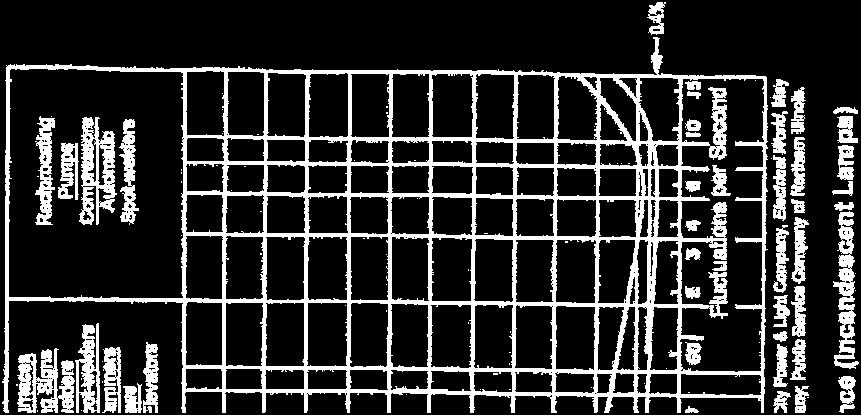
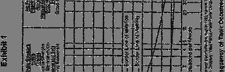
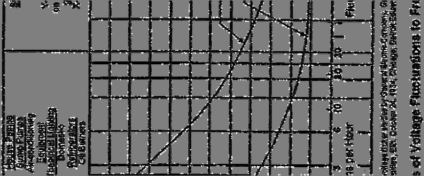
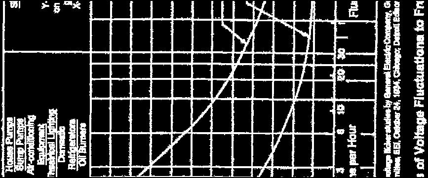
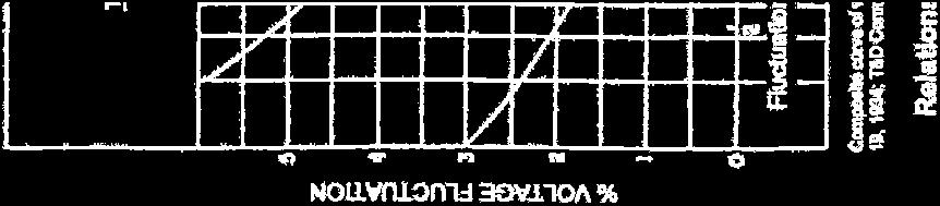
12 Voltage Balance All three-phase generation shall produce balanced 60 Hz voltages. Voltage unbalance attributable to the Generation Facility Owner combined generation and load shall not exceed 1.0% measured at the point-of-service. Voltage unbalance is defined as the maximum phase deviation from average as specified in ANSI C84.1, American National Standard for Electric Power Systems and Equipment Voltage Ratings, 60 Hertz Current Balance Phase current unbalance attributable to the Generation Facility Owner combined generation and load shall not exceed that which would exist with balanced equipment in service, measured at the point-of-common coupling. Situations where high unbalance in voltage and/or current originate from the transmission system are to be addressed in the Connection Agreement Harmonics and Flicker The Generation Facility Owner shall take responsibility for limiting harmonic voltage and current distortion and/or voltage flicker 2 caused by their generation equipment. Limits for harmonic distortion (including inductive telephone influence factors) are consistent with those published in the latest issues of ANSI/IEEE 519, "Recommended Practices and Requirements for Harmonic Control in Electrical Power Systems." Specific HE harmonics and flicker criteria are given in Appendix C. HE criteria requires that flicker occurring at the point of compliance shall remain below the Border Line of Visibility curve on the IEEE/GE curve for fluctuations less than 1 per second or greater than 10 per second. However, in the range of 1 to 10 fluctuations per second, voltage flicker shall remain below 0.4% (see Appendix C, Exhibit 1). Depending upon the nature of the generation and its location, HE may require the installation of a monitoring system to permit ongoing assessment of compliance with these criteria. The monitoring system, if required, will be installed at the Generation Facility Owner s expense. Situations where high harmonic voltages and/or currents originate from the transmission system are to be addressed in the Connection Agreement. 4.0 REQUIREMENTS FOR OPERATION The Generation Facility Owner is responsible for operating their generation with full regard for the safe practices of, and with full cooperation under the supervision of, the HE System Control A Generation Facility Owner s generation shall not supply power into the HE transmission system unless a specific written agreement has been made to supply power to the HE transmission system. 2 Flicker is an objectionable, low frequency, voltage fluctuation which can be observed through changes in intensity or color of illumination. 10
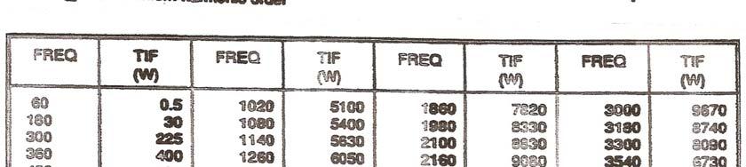
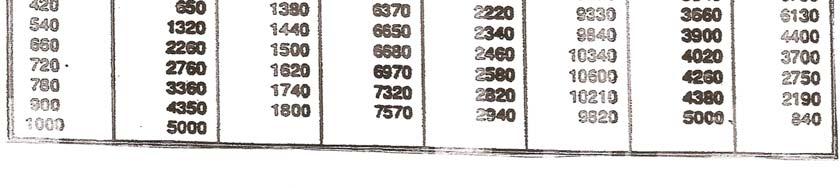
13 Under no circumstances shall a Generation Facility Owner energize HE transmission facilities which have been de-energized. Circuits which are electrically disconnected from the HE transmission system and are energized by a Generation Facility Owner constitute a potential safety hazard for both HE transmission personnel and the general public. Also, the energizing of such circuits at abnormal voltage or frequency could cause damage to electrical equipment of both the HE transmission system and the generation. HE reserves the right to disconnect service to any generator facility if, for any reason, HE deems the continuation of the generator is, or may be, a detriment to the operation of the HE Transmission System. The minimum requirements for operation of generation on the HE Transmission System are contained herein. 4.1 Synchronization The Generation Facility Owner shall assume all responsibility for properly synchronizing their generation for operation with the HE Transmission System. Upon loss of the HE supply, the Generation Facility Owner shall immediately and positively cause the generation to be separated from the HE system. Synchronizing of generation to the HE Transmission System may be, at HE s discretion, performed under the direction of the HE System Control Center. 4.2 Voltage Schedule/Power Factor Specification of the generator voltage schedule will be determined under the direction of the HE System Control Center. See also NERC Standard VAR-002, B.R2 for details. A steady-state deviation from this schedule between +0.5% to 0.5% of the nominal voltage will be permissible. Nominal HE system voltages are 345, 230, 161, 138, and 69 kv. In certain unusual situations where a voltage schedule is inappropriate, HE, initially and in the future, may substitute adherence to a specified voltage schedule with a specified power factor. A steady state deviation from this power factor within +2% to 2% will be permissible. 4.3 Voltage Range The generation facility must be capable of continuous non-interrupted operation within a steady-state voltage range during system normal and single facility outage conditions. This range is from 92% to 105% of the nominal transmission voltage. HE system nominal voltages are as indicated in Section 4.2 above. During emergency and/or transient system conditions, as voltage may temporarily be outside the 92% to 105% range, all reasonable measures should be taken to avoid tripping of the generation facility due to high or low voltage. 4.4 Frequency Range The generation facility must be capable of continuous, non-interrupted operation in the frequency range of 59.5 to 60.5 Hz. Limited time, non-interrupted operation is 11
14 also expected outside this frequency range in accordance with the generator manufacturer s recommendation or the figure contained in Appendix D. 4.5 Net Demonstrated Real and Reactive Capabilities The Net Demonstrated real capability in accordance with ECAR Document No. 4, (to be superceded by RFC document MOD-024-RFC-01 in 2009) must be provided to HE annually. HE reserves the right to witness these tests. In addition, individual generators in the generation facility must make available the full steady-state over- and under-excited reactive capability given by the manufacturer s generator capability curve at any MW dispatch level. Tests which demonstrate this capability must be conducted and documented not more than at five year intervals in accordance with ECAR Document 4, (to be superceded by RFC document MOD-025- RFC-01 in 2009). Such documentation shall be provided to HE. HE reserves the right to witness these tests. 4.6 Other Applicable Operating Requirements In order to assure the continued reliability of the HE Transmission System, the Generation Facility Owner may be requested to adhere to other operating requirements and/or encouraged to adopt common operating practices. These include the coordination of maintenance scheduling, performance not to exceed a specified forced outage rate, operations procedures during system emergencies, participation in control area operating reserves, provisions for backup fuel supply or storage, and provisions for emergency availability identified by the North American Electric Reliability Council. 3 HE, as the Transmission Provider, may require the Generation Facility Owner to provide Interconnected Operation Services defined by NERC standards. Such requirements shall be addressed in the Connection Agreement with the Generation Facility Owner. Conformance with applicable requirements in ECAR Documents, particularly Document 4, Criteria and Methods for the Uniform Rating of Generation Equipment, (to be superceded by RFC document MOD-024 and MOD-025 in 2009), NERC Standard VAR-002, and RFC document PRC-002-RFC-1 Disturbance Monitoring and Reporting Requirements is required. All data reportable to RFC and/or NERC shall also be made available to HE. 4.7 Make-Before-Break Transfer Make-before-break transfer is only permitted between two live sources which are in, or close to, synchronism. A transfer switch designed for automatic make-before break transition shall be equipped with logic to prevent a transfer if the specifications for either the Generation Facility Owner or the HE transmission system source fall outside of the synchronizing requirements recommended by the generator equipment manufacturer. Switch transfers made when the synchronizing requirements cannot be met shall be of the break-before-make type of transfer. The time that the Generation Facility Owner s generation is permitted to operate in parallel with the HE Transmission System during a make-before-break transfer shall be no greater than 100 milliseconds (6 cycles). 3 North American Electric Reliability Council, Reliability Considerations for Integrating Non-Utility Generating Facilities with the Bulk Electric Systems, January
15 4.8 Operating Restrictions Situations necessitating generation curtailments or forced outages as the result of unavailability of transmission facilities owned and/or operated by HE are to be addressed in a Connection Agreement with the Generation Facility Owner. 5.0 PROTECTIVE RELAYING Generation Facility Owner relay requirements are summarized in Section 3.2. Specific requirements are noted below. 5.1 Parallel Generation Facility The following utility-grade relays shall be provided by the Generation Facility Owner for protection of the HE system. Use of the transfer trip receiver is conditional as set forth in Section 5.2, HE Facilities. All relays specified for the protection of the HE system, including time delay and auxiliary relays, shall be approved by HE. Relay operation for any of the listed functions shall initiate immediate separation of the Generation Facility Owner s generation from the HE System. Relay Frequency Overvoltage Undervoltage Ground Detector Directional Overcurrent Transfer Trip Receiver Function To detect underfrequency and overfrequency operation. To detect overvoltage operation. To detect undervoltage operation. To detect a circuit ground on the HE system (applicable to three-phase circuits only). To detect the directional flow of current in excess of a desired limit. To provide tripping logic to the generation for isolation of the generation upon opening of the HE supply circuits. Directional Power* To detect, under all system conditions, a loss of HE primary source. The relay shall be sensitive enough to detect transformer magnetizing current supplied by the generation. 13
16 * If an agreement exists to supply power to the HE system, additional relays may be required to provide adequate protection for the HE system. The purpose of these relays is to detect the Generator Owner s energization of an HE circuit that has been disconnected from the HE system, to detect the generation operating at an abnormal voltage or frequency, or to detect a fault or abnormal condition on the HE system for which the Generation Facility Owner shall separate their generation. Output contacts of these relays shall directly energize the trip coil(s) of the generator breaker or an intermediate auxiliary tripping relay which directly energizes the breaker trip coil(s). The relaying system shall have a source of power independent from the ac system or immune to ac system loss or disturbances (e.g., dc battery and charger) to assure proper operation of the protection scheme. Loss of this source shall cause removal of the generation from the HE system. The protective relays required by HE and any auxiliary tripping relay associated with those relays shall be utility-grade devices. Utility grade relays are defined as follows: 1. Meet ANSI/IEEE Standard C37.90, "Relays and Relay Systems Associated with Electric Power Apparatus." 2. Have relay test facilities to allow testing without unwiring or disassembling the relay. 3. Have appropriate test plugs/switches for testing the operation of the relay. 4. Have targets to indicate relay operation. HE will specify settings for the generation s HE-required relays to assure coordination between the generation protective equipment and the HE system relays. It is the Generation Facility Owner s responsibility to determine that their internal protective equipment coordinates with the required HE protective equipment and is adequate to meet all applicable standards to which the generation is subject. HE further reserves the right to modify relay settings when deemed necessary to avoid safety hazards to utility personnel or the public and to prevent any disturbance, impairment, or interference with HE's ability to serve other customers. 5.2 HE Facilities If at any time it is determined that the use of the above relay systems cannot provide adequate protection to the HE system, the Generation Facility Owner shall additionally furnish and install at their expense, upon the request of HE, a transfer trip receiver(s) at his facility to receive tripping signals originating from a HE location(s). 14
17 This additional protection would also necessitate, at the Generation Facility Owner s expense, the purchase and installation of transfer trip equipment at the HE location(s) and a communication channel between the HE location(s) and the generation facility. 5.3 Other Protection Requirements The following items should be coordinated with each other: Volts/Hz and overexcitation protection/limiting. Loss-of-excitation and underexcitation limiting. 6.0 TESTING AND MAINTENANCE The Generation Facility Owner shall permit testing and maintenance of devices and control schemes provided by the Generation Facility Owner for the protection of the HE Transmission System by an HE approved organization. Included in the testing and maintenance will be any initial set up, calibration, and check out of the required rotective devices, periodic routine testing and maintenance, and any testing and maintenance required as the result of changes to protective devices by the Generation Facility Owner or HE. All testing and maintenance performed by the HE approved organization shall be under the general surveillance of HE. This may include circuit breakers, circuit switches, power fuses, instrument transformers, switches, surge arresters, bushings, relays, and associated equipment (including battery and battery charger). Maintenance procedures are detailed in the HE Maintenance Strategy Power Delivery xx. Also, a copy of all test and maintenance reports shall be forwarded to HE. If the Generation Facility Owner s testing and maintenance program is not performed to the satisfaction of HE or at the required maintenance interval, HE reserves the right to inspect, test, or maintain the protective devices required for the protection of the HE transmission system. If the Generation Facility Owner s protective relaying is determined to be unsatisfactory, HE reserves the authority to disconnect the generation from the HE System. All costs associated with the testing and maintenance of devices provided by the Generation Facility Owner for the protection of the HE transmission system, including costs incurred by HE in performing any necessary tests or inspections, shall be the responsibility of the Generation Facility Owner. 15
18 7.0 METERING AND TELEMETRY The Generation Facility Owner shall be responsible for the installation and operating costs of the metering equipment at the delivery point. The metering equipment will include potential and current transformers, meters and test switches. The accuracy of the instrument transformers and meters will be 0.3 percent or better. The secondary wiring and burdens of the instrument transformers will be configured so that they do not degrade the accuracy of the metering equipment to less than 0.3 percent. The metering equipment will be tested periodically as defined in the connection agreement and the test results will be available to all involved parties. The meters, test switches and wiring termination equipment will be sealed and the seal may be broken only when the meters are to be tested, adjusted or repaired. Proper authorities in both parties will be notified when seals are broken. At least (N-1) metering elements will be used to measure all real and reactive power crossing the metering point, where N is the number of wires in service including the ground wire. Bidirectional energy flows including watt-hour and var-hour will be separately measured on an hourly basis. Depending on the tariffs to be applied, appropriate demand quantities will be metered in terms of kilowatts, kilovars or kilovoltamperes. The meters will have a separate register for loss compensation. If required, voltage measurements will be provided. If, at the discretion of HE, the generation necessitates real-time telemetry to the HE System Control Center, the Generation Facility Owner shall install and operate at their expense the communication channel, the HE approved telemetry equipment and associated devices. At the discretion of HE, generation control facilities and supervisory control and data acquisition of specific electrical devices from the HE System Control Center may be necessary to integrate the generation into HE s control area. Such additional facilities, including required communication channels, shall, if required, be furnished and installed at the Generation Facility Owner's expense. The requirement for data acquisition and control will depend on the generation capacity, system location and voltage, and the net generation input into HE System. Suitable telemetry equipment will be installed at the metering point to provide real-time telemetry data to HE and to all other participating parties. Telemetry equipment will include transducers, remote terminal units, modems, telecommunication lines, and any other equipment of the same or better function. The remote terminal unit, or equivalent device, must have multiple communication ports to allow simultaneous communications with all participating parties. That device will accommodate data communication requirements specified by each participating parties control center, including communication protocol, rate and mode (either synchronous or asynchronous). All metered values provided to the telemetry equipment will originate from common metering equipment. All transducers used for telemetry will have at least 0.2 percent accuracy. As part of real-time data to be provided, HE has the right 16
19 to require the status and remote control of switching devices at the Receipt and/or Delivery Points. A continuous, accumulating record of megawatt-hours and megavar-hours will be provided by means of the registers on the meter. Freezing accumulation data for transmission will be taken every clock hour. The freezing signals synchronized to within 2 seconds of Universal Coordinated Time must be provided by only one of the agreed upon participating parties. If the freeze signal is not received within a predefined time window, the remote terminal unit, or equivalent device, will be capable of freezing data with its own internal clock. The metering, if external power supply is required, and telemetry equipment will be powered from a reliable power source, such as a station control battery, in order to allow the equipment to be continuously operational under any power outage situations. Proper surge protection will be provided for each communication link to protect communication hardware from ground-potentialrise due to any fault conditions. A separate communication media shall be provided to allow HE to remotely retrieve billing quantities from the meters. When real-time telemetry is required, a back-up data link must be provided in case of the outage of the primary telemetry line. The backup link can be a data communication link between involved control centers; the party requesting service is responsible for furnishing the back-up link. Data acquisition and control information will typically include, but not be limited to: 1. desired generation MW set point, 2. automatic generation control status (on, off), 3. generator availability, 4. generation MW, Mvar output, 5. generator minimum and base MW capability, 6. generator MW AGC high limit and low limit, 7. connection facilities breaker status/control/alarms, 8. connection facilities MW and MVAr line values and bus voltage, and 9. generator and substation metering (MWh) data. 8.0 COMMUNICATIONS 8.1 Voice Communications A. Normal At HE s request, the Generation Facility Owner shall provide a dedicated voice communication circuit to the HE System Control Center (SCC). Such a dedicated voice communication circuit would originate from the Owner s office staffed 24 hours a day and would be typically required for generation facility synchronization and operation within HE s Control Area. All other normal voice communication concerning facility operations shall be conducted through the public telephone network to the SCC phone number(s) issued by HE. B. Emergency Voice communications in the event of a transmission system or capacity emergency shall use the dedicated voice circuits, or public telephone 17
20 network and phone number(s) designated for emergency use. In the event of a transmission system or capacity emergency, the Generation Facility Owner may be notified by the HE System Control Center. Specific instructions may also be given regarding the operation of the Owner s unit(s) depending on the nature of the emergency. These instructions may consist of voltage schedule changes, real and/or reactive dispatch changes, or instructions to shut down or start-up the Owner s unit(s). It is the Owner s responsibility to ensure that the unit operators follow all instructions given by the HE Control Center during system emergencies. 9.0 COSTS INCURRED The Generation Facility Owner shall reimburse all costs incurred by HE to provide operation of their generation. The costs include but are not limited to: 1. Each review of the engineering and engineering drawings associated with the generation. 2. All metering not covered under the transmission tariff of general applicability. 3. The necessary facility modifications on the HE transmission system to adequately accommodate the operation of the Generation Facility Owner s generation. 4. HE facility replacements, modifications, and/or enhancements due to exceeded ratings directly caused by or which could potentially be caused by the power flow attributed to the generation. 5. All communications circuits required for telemetering, protective relaying, and/or voice communications with the generation. 6. All protective devices to be provided by the Generation Facility Owner for the protection of the HE transmission system. 7. All protective relaying, including the transfer trip transmitter(s), receiver(s), and associated equipment, not on the Generation Facility Owner's premises required by HE due to the addition of the generation. 8. All protective relaying required to protect the generation from faults and abnormal system operating conditions. 9. All additional regulating and control devices required to meet the conditions set forth in Section 4.0. This would include any equipment necessary for suppression of harmonic current and/or voltages. 10. HE equipment replacements or modifications due to an increase in available short circuit fault current directly caused by the addition of the Generation Facility Owner s equipment. 11. Calibration, testing, and maintenance of relays and protective devices provided by the Generation Facility Owner for the protection of the HE transmission system. 18
21 12. All telemetering equipment to provide necessary telemetry to the HE System Control Center. 13. Future changes associated with the generation due to changing conditions on the HE system. 14. All studies performed by HE pertaining to the generation DESIGN REVIEW The Generation Facility Owner is responsible for submitting all specifications and detailed plans to HE for review and approval prior to receiving permission to connect to the HE transmission system. HE requires notification in letter form for the proposed installation of any generation, including an emergency generator utilizing a make-before-break transfer switch. In order to allow for timely exchange of information, this notification should be provided during the preliminary planning stages of the proposed facility. If the proposed installation is intended to either displace load or to actually supply energy to the HE transmission system, a Notification of Intent to Install and Operate Generation (NIOG), as shown in Appendix E, must be submitted. The NIOG document should be submitted to HE at least six (6) months prior to the proposed in-service date for load displacement installations and twelve (12) months or more where generation will be supplied to the HE transmission system. Where proposed generation additions require changes to the HE transmission system, earlier notification may be necessary. HE requires a review of the Generation Facility Owner s plans for the generation in order to provide for compatibility of design and operation with the HE transmission system Notification of Intent The Generation Facility Owner is required to complete and forward a NIOG to an HE customer service representative with the appropriate deposit and all necessary attachments which shall include: 1. A summary, signed by the Generation Facility Owner management, that provides a general description of the intended manner of operation for the generation. 2. Three copies of drawings and specifications prepared and approved by a registered professional engineer adequately detailing the facility location and proposed location of the generation facilities with respect to the Generation Facility Owner's desired point of electric service and the appropriate disconnecting devices identified in Section Three copies of a comprehensive single-line diagram prepared and approved by a registered professional engineer. This information must comprehensively show the Generation Facility Owner's intended configuration for operation 19
22 including switching devices, transformers, generation facility, protective devices, metering devices, capacitors, proposed conductor sizes, etc. HE will review the information supplied with the NIOG and provide appropriate engineering and operational comments and/or concerns that must be addressed and jointly resolved with HE. This review will also include a summary addressing other tangible responsibilities and associated estimated costs the Generation Facility Owner will incur as reflected in Section 9.0 of this document Facility Data At least three (3) months prior to the in-service date, the following data shall be received by HE. If the data is not available three months prior to the in-service date, the Generation Facility Owner shall provide estimates based on their design information. Such data shall be identified as "estimated" and replaced with actual data by the Generation Facility Owner as it becomes available prior to installation. The purpose of generation facility data to be provided to HE by the Generation Facility Owner is to ensure proper coordination to protect against equipment or facility damage, to mitigate safety hazards to utility personnel and the public, and to minimize disturbances, impairment, or interference with HE s ability to serve other transmission system users Data on Equipment to be Installed a. Interrupting Devices and Relays - Complete manufacturer's data for interrupting devices and relays or fuses used for the protection of the HE system and the generation. b. Power Transformers - Complete nameplate or test sheet data, including manufacturer, serial number, high- and low-side voltage taps, kva ratings, impedance, load loss and no load loss watts, high- and lowside voltage winding connections, low-side voltage winding grounding (if used), and high voltage inrush current. c. Power Capacitors - Location, kv and kvar rating of capacitor banks, number of units, and bank configuration Data on the generation protection equipment, including make-before-break transfer switches, fuses, breakers, relays, relay settings associated with the proposed generation, and detailed schematic diagrams of protective relaying proposed for the HE transmission system. Complete manufacturer's data and specifications for make-before-break transfer switches, including transfer times and conditions of transfer, testing procedures, equipment schematics, and backup protection Information on characteristics of load, such as initial and near future expected load, power factor of such load, and dynamic (flicker, harmonics, etc.) character of such load Minimum and maximum required low-side operating voltages. 20
23 Generator Data: a. Type (synchronous, induction, dc with solid-state inverter, etc.); b. Nameplate data and ratings, including any rectifying, regulating, or inverting equipment; c. Harmonic content at full rated output; d. Detailed Dynamic Performance Data in accordance with Appendix B. e. Real and Reactive capabilities at scheduled voltages Electric one-lines and schematic diagrams showing the generation, the interconnecting facility with the HE transmission system, and the protective relaying INSPECTION REQUIREMENTS Before a generation facility can be energized, it must pass a final inspection by HE personnel. HE will inspect all substation equipment from the point of interconnection to the first protective fault interrupting device. This may include circuit breakers, circuit switchers, power fuses, instrument transformers, switches, surge arresters, bushings, and relays and associated equipment (including battery and battery chargers). The inspection will consist of a visual inspection of all major equipment as well as review of required test results FINAL DOCUMENTATION HE shall receive final documentation of the generation facility that replaces the above specifications and data submitted for the design review under Section 10.2 once the facility is ready for operation. Prior to operation of a generation facility, the Generation Facility Owner shall supply to HE three copies of all final electric one-lines, equipment data, and schematic diagrams. Subsequent revisions affecting the generation shall be documented with three copies of the revised electric one-line and schematic diagrams APPROVAL The construction, testing, and maintenance of the protective equipment provided by the Generation Facility Owner for protection of the HE transmission system shall be subject to review and approval by HE. Prior to establishing service for operation, the Generation Facility Owner shall obtain approval from HE for the generation, electrical equipment specifications, and operating procedures. 21
24 Final approval for operation of a Generation Facility Owner's generation will be issued by HE. A signed contractual document with HE for the generation is required for final approval. Failure to meet any of the requirements stated herein to the satisfaction of HE may result in a refusal to permit operation of the generation. Review and approval by HE of the proposed generation facility specifications and plans shall not be construed as confirming or endorsing the design or warranting the safety, durability, reliability, adequacy, or otherwise of the generation facility. Note that the proposing entity must have approval from MISO before receiving any approval from HE SPECIAL PROVISIONS Special provisions may be made with operators of small power production facilities and other co-generators pursuant to rules of the Federal and/or State agencies of the applicable regulatory jurisdiction COORDINATION WITH OTHER CODES, STANDARDS, AND AGENCIES The information contained in this document is supplementary to and does not ntentionally conflict with or supersede the National Electric Code (NEC) as approved by the American National Standards Institute (ANSI) or such federal, state and municipal laws, ordinances, rules or regulations as may be in force within the cities, towns or communities in which HE furnishes electric service. It is the responsibility of the Generation Facility Owner to conform to all applicable national, state and local laws, ordinances, rules, regulations, codes, etc INDEMNIFICATION The use and reliance upon the information contained in this document shall in no way relieve the Generation Facility Owner from the responsibility to meet NEC and NESC requirements governing their design, construction, operation, and materials. The Generation Facility Owner, for itself, its successors, assigns and subcontractors will be required to pay, indemnify and save HE, its successors and assigns, harmless from and against any and all court costs and litigation expenses, including legal fees, incurred or related to the defense of any action asserted by any person or persons for bodily injuries, death or property damage arising or in any manner growing out of the use and reliance upon the information provided by HE. Reliance upon the information in this document shall not relieve the Generator Facility Owner from responsibility for the protection and safety of the general public. 22
25 APPENDIX A: Figures Figure 1 Typical Generation Tap Line Supply Configurations Figure 2 Typical Generation Arrangements for Transmission Bus Connection 23
26 24
27 25
28 APPENDIX B: Generation Dynamic Performance Data 26
29 Customer Name Date / / UNIT RATINGS GENERATOR DATA kva F Voltage Power Factor H2 psig Speed (RPM) Connection (e.g. Wye) Short Circuit Ratio Frequency, Hertz Stator Amperes at Rated kva Field Volts REACTANCE DATA (PER UNIT-RATED KVA) Synchronous saturated Synchronous unsaturated Transient saturated Transient unsaturated Subtransient saturated Subtransient unsaturated Negative Sequence saturated Negative Sequence unsaturated Zero Sequence saturated Zero Sequence unsaturated Leakage Reactance DIRECT AXIS QUADRATURE AXIS Xdv Xqv Xdi Xqi X dv X qv X di X qi X dv X qv X di X qi X2v X2i X0v X0I Xlm FIELD TIME CONSTANT DATA (SEC) Open Circuit T do T qo Three-Phase Short Circuit Transient T d3 T q Line to Line Short Circuit Transient T d2 Line to Neutral Short Circuit Transient T d1 Short Circuit Subtransient T d T q Open Circuit Subtransient T do T qo ARMATURE TIME CONSTANT DATA (SEC) Three Phase Short Circuit Line to Line Short Circuit Line to Neutral Short Circuit Ta3 Ta2 Ta1 ARMATURE WINDING RESISTANCE DATA (PER UNIT) Positive Negative Zero R1 R2 R0 Rotor Short Time Thermal Capacity I2 2 t = Field Current at Rated kva, Armature Voltage and PF = amps Field Current at Rated kva and Armature Voltage, 0 PF = amps Three Phase Armature Winding Capacitance = microfarad Field Winding Resistance = ohms C Armature Winding Resistance (Per Phase) = ohms C 27
30 COMBINED TURBINE-GENERATOR-EXCITER INERTIA DATA (Provide one) Inertia Constant, H = kw sec/kva Moment-of-Inertia, WR 2 = lb. ft. 2 CURVES Saturation, Vee, Reactive, Capacity Temperature Correction RATINGS GENERATOR STEP-UP TRANSFORMER DATA Capacity Self-cooled/maximum nameplate / kva Voltage Ratio Generator side/system side / kv Winding Connections Low V/High V (Delta or Wye) / Fixed Taps Available Present Tap Setting Load Tap Changer? Yes No Range (+/-%) IMPEDANCE Positive Z1 (on self-cooled kva rating) % Zero Z0 (on self-cooled kva rating) % EXCITATION SYSTEM Identify appropriate IEEE model block diagram of excitation system and power system stabilizer (PSS) for computer representation in power system stability simulations and the corresponding excitation system and PSS constants for use in the model. Also, identify the source(s) (e.g., vendor or field tests) of the model and modeling data. GOVERNOR SYSTEM Identify appropriate IEEE model block diagram of governor system for computer representation in power system stability simulations and the corresponding governor system constants for use in the model. Also, identify the source(s) (e.g., vendor or field tests) of the model and modeling data. 28
31 APPENDIX C: HE Voltage Flicker Criteria and Harmonic Distortion Criteria 29
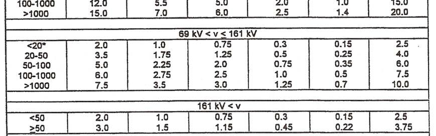
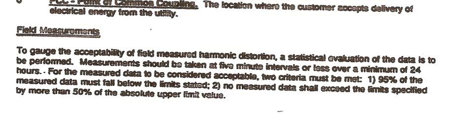
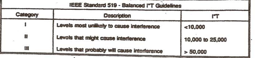
32 HE Voltage Flicker Criteria and Harmonic Distortion Criteria This document summarizes HE s policy on voltage flicker and harmonic distortion for customers connected to the electrical system via a Company dedicated transformer or a Customer owned transformer. The term Company is defined as Hoosier Energy REC, Inc (HE). The term Customer is defined as the party connected to the HE System. I. POINT OF COMPLIANCE The point where the Company dedicated transformer or Customer owned transformer connects to the Company system will be the point where compliance with the voltage flicker and harmonic distortion requirements are evaluated. II. VOLTAGE FLICKER CRITERIA The Company requires that the voltage flicker occurring at the point of compliance shall remain below the Border Line of Visibility curve on the IEEE/GE curve for fluctuations less than 1 per second or greater than 10 per second (see Exhibit 1). In the range of 1 to 10 fluctuations per second, the voltage flicker shall remain below 0.4%. The Customer agrees that under no circumstances will it permit the voltage flicker to exceed the Company criteria, whether or not complaints are received or service/operational problems are experienced on the Company subtransmission or transmission system. Should complaints be received by the Company or other operating problems arise, or should the Customer flicker exceed the borderline of visibility curve, the Customer agrees to take immediate action to reduce its flicker to a level at which flicker complaints and service/operational problems are eliminated. Corrective measures could include, but are not limited to, modifying production methods/ materials or installing, at the Customer s expense, voltage flicker mitigation equipment such as a static var compensator. The Company will work collaboratively with the Customer to assess problems, identify solutions and implement mutually agreed to corrective measures. If the Customer fails to take corrective action after notice by the Company, the Company shall have such rights as currently provided for under its tariffs, which may include discontinuing service, until such time as the problem is corrected. III. HARMONIC DISTORTION CRITERIA - The Company also requires that the Customer s operation be in compliance with the Company s Harmonic Distortion Guidelines (see Exhibit 2). These requirements are based on IEEE Standard 519, IEEE Recommended Practices and Requirements for Harmonic Control in Electric Power Systems. The Customer agrees that the operation of motors, appliances, devices or apparatus served by its system and resulting in harmonic distortions in excess of the Company s Requirements will be the Customer s responsibility to take immediate action, at the Customer s expense, to comply with the Company s Harmonic Distortion Requirements. The Company will work collaboratively with the Customer to assess problems, identify solutions and implement mutually agreed to corrective measures. 30
33 If the Customer fails to take corrective action after notice by the Company, the Company shall have such rights as currently provided for under its tariffs, which may include discontinuing service, until such time as the problem is corrected. 31


34 Exhibit 1 32


35 Exhibit 2 33

36 Exhibit 3 34


37 Exhibit 4 35
38 APPENDIX D: Generation Abnormal Frequency Operating Allowance 36

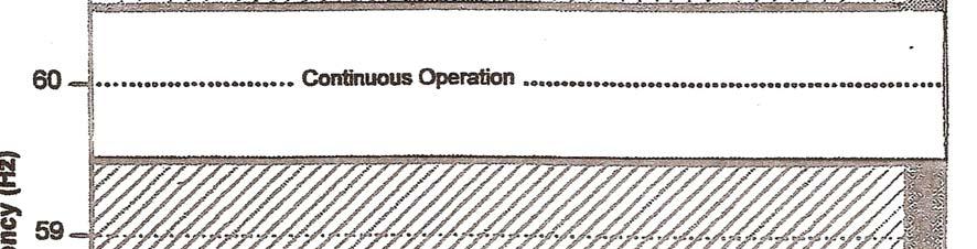

39 Generation Abnormal Frequency Operating Allowance 37
HOOSIER ENERGY REC, INC. Requirements for Connection of Non Generation Facilities
 HOOSIER ENERGY REC, INC Requirements for Connection of Non Generation Facilities to the HE Transmission System January 2009 Table of Contents 1.0 INTRODUCTION 1 2.0 TAP CONNECTION DEFINITION AND REQUIREMENTS
DP&L s Technical Requirements for Interconnection and Parallel Operation of Distributed Generation
 DP&L s Technical Requirements for Interconnection and Parallel Operation of Distributed Generation Technical Requirements for Interconnection and Parallel Operation of Distributed Generation Single Phase
BED INTERCONNECTION TECHNICAL REQUIREMENTS
 BED INTERCONNECTION TECHNICAL REQUIREMENTS By Enis Šehović, P.E. 2/11/2016 Revised 5/19/2016 A. TABLE OF CONTENTS B. Interconnection Processes... 2 1. Vermont Public Service Board (PSB) Rule 5.500... 2
OPERATING, METERING AND EQUIPMENT PROTECTION REQUIREMENTS FOR PARALLEL OPERATION OF LARGE-SIZE GENERATING FACILITIES GREATER THAN 25,000 KILOWATTS
 OPERATING, METERING AND EQUIPMENT PROTECTION REQUIREMENTS FOR PARALLEL OPERATION OF LARGE-SIZE GENERATING FACILITIES GREATER THAN 25,000 KILOWATTS AND MEDIUM-SIZE FACILITIES (5,000-25,000KW) CONNECTED
OPERATING, METERING, AND EQUIPMENT PROTECTION REQUIREMENTS FOR PARALLEL OPERATION OF LARGE-SIZE GENERATING FACILITIES GREATER THAN 2,000 KILOWATTS
 OPERATING, METERING, AND EQUIPMENT PROTECTION REQUIREMENTS FOR PARALLEL OPERATION OF LARGE-SIZE GENERATING FACILITIES GREATER THAN 2,000 KILOWATTS CONNECTED TO THE DISTRIBUTION SYSTEM ORANGE AND ROCKLAND
Generation Interconnection Requirements at Voltages 34.5 kv and Below
 Generation Interconnection Requirements at Voltages 34.5 kv and Below 2005 March GENERATION INTERCONNECTION REQUIREMENTS AT 34.5 KV AND BELOW PAGE 1 OF 36 TABLE OF CONTENTS 1. INTRODUCTION 5 1.1. Intent
Wind Power Facility Technical Requirements CHANGE HISTORY
 CHANGE HISTORY DATE VERSION DETAIL CHANGED BY November 15, 2004 Page 2 of 24 TABLE OF CONTENTS LIST OF TABLES...5 LIST OF FIGURES...5 1.0 INTRODUCTION...6 1.1 Purpose of the Wind Power Facility Technical
E N G I N E E R I N G M A N U A L
 1 1 1.0 PURPOSE The purpose of this document is to define policy and provide engineering guidelines for the AP operating companies (Monongahela Power Company, The Potomac Edison Company, and West Penn
ISO Rules Part 500 Facilities Division 502 Technical Requirements Section Wind Aggregated Generating Facilities Technical Requirements
 Applicability 1(1) Section 502.1 applies to the ISO, and subject to the provisions of subsections 1(2), (3) and (4) to any: (a) a new wind aggregated generating facility to be connected to the transmission
Technical Requirements For Generation Connected to The ODEC System
 Old Dominion Electric Cooperative Technical Requirements For Generation Connected to The ODEC System March 30, 2010 1 2 Table of Contents Topics Page Number Disclaimer.. 3 Perquisites.. 3 Applicability..
TECHNICAL SPECIFICATIONS AND OPERATING PROTOCOLS AND PROCEDURES FOR SMALL GENERATION INTERCONNECTIONS
 TECHNICAL SPECIFICATIONS AND OPERATING PROTOCOLS AND PROCEDURES FOR SMALL GENERATION INTERCONNECTIONS Puget Sound Energy, Inc. PSE-ET-160.60 October 30, 2007 TABLE OF CONTENTS 1. INTRODUCTION...1 1.1 GENERAL
TECHNICAL SPECIFICATIONS AND OPERATING PROTOCOLS AND PROCEDURES FOR INTERCONNECTION OF GENERATION FACILITIES NOT SUBJECT TO FERC JURISDICTION
 TECHNICAL SPECIFICATIONS AND OPERATING PROTOCOLS AND PROCEDURES FOR INTERCONNECTION OF GENERATION FACILITIES NOT SUBJECT TO FERC JURISDICTION Document 9022 Puget Sound Energy, Inc. PSE-TC-160.70 December
TECHNICAL SPECIFICATIONS AND OPERATING PROTOCOLS AND PROCEDURES FOR INTERCONNECTION OF LARGE GENERATION FACILITIES. Document 9020
 TECHNICAL SPECIFICATIONS AND OPERATING PROTOCOLS AND PROCEDURES FOR INTERCONNECTION OF LARGE GENERATION FACILITIES Document 9020 Puget Sound Energy, Inc. PSE-TC-160.50 December 19, 2016 TABLE OF CONTENTS
Table of Contents. Introduction... 1
 Table of Contents Introduction... 1 1 Connection Impact Assessment Initial Review... 2 1.1 Facility Design Overview... 2 1.1.1 Single Line Diagram ( SLD )... 2 1.1.2 Point of Disconnection - Safety...
Embedded Generation Connection Application Form
 Embedded Generation Connection Application Form This Application Form provides information required for an initial assessment of the Embedded Generation project. All applicable sections must be completed
Facility Interconnection Requirements for Colorado Springs Utilities Version 03 TABLE OF CONTENTS
 TABLE OF CONTENTS 1.0 INTRODUCTION (NERC FAC-001 Requirement R1, R2)... 4 2.0 INTERCONNECTION REQUIREMENTS FOR GENERATION, TRANSMISSION, AND END-USER FACILITIES (NERC FAC-001 Requirements R3 & R4)... 4
GREAT RIVER ENERGY GREAT RIVER ENERGY GENERATION INTERCONNECTION GUIDELINES. Revision 4
 GREAT RIVER ENERGY GREAT RIVER ENERGY GENERATION INTERCONNECTION GUIDELINES Revision 4 December, 2010 TABLE OF CONTENTS General Requirements... 1 A, Purpose... 1 B, MISO Interconnection Requirements...2
Transmission Interconnection Requirements for Inverter-Based Generation
 Transmission Requirements for Inverter-Based Generation June 25, 2018 Page 1 Overview: Every generator interconnecting to the transmission system must adhere to all applicable Federal and State jurisdictional
ISO Rules Part 500 Facilities Division 502 Technical Requirements Section SCADA Technical and Operating Requirements
 Section 502.8 SCADA Technical and Operating Applicability 1 Section 502.8 applies to: (a) the legal owner of a generating unit: (i) connected to the transmission facilities in the balancing authority area
PJM Manual 07:: PJM Protection Standards Revision: 2 Effective Date: July 1, 2016
 PJM Manual 07:: PJM Protection Standards Revision: 2 Effective Date: July 1, 2016 Prepared by System Planning Division Transmission Planning Department PJM 2016 Table of Contents Table of Contents Approval...6
Oklahoma Gas and Electric Co. Facility Connection Requirements MAINTAINED BY. Transmission Planning Engineering Department
 Oklahoma Gas and Electric Co. Facility Connection Requirements MAINTAINED BY Transmission Planning Engineering Department Table of Contents Transmission and Generation Facility Interconnections... 3 Attachment
I WP Asset # I ~:2 3. I Review Annual. ~c~~ Date: 'l/j(j/! ZL>IJ,...
 - District Standard - FAC Facility Design, Connections 950.001 and Maintenance CHELAN COUNTY ~ PUBLIC UTILITY DISTRICT Owned By The People~ Serve Facility Connection Requirements Page 1 of 101 EFFECTIVE
The Connecticut Light and Power Company
 The Connecticut Light and Power Company and The United Illuminating Company Exhibit B - Generator Interconnection Technical Requirements May 12, 2010 Page 1 of 26 Table of Contents 1. SCOPE... 3 2. GENERAL
Southern Company Interconnection Requirements for Inverter-Based Generation
 Southern Company Interconnection Requirements for Inverter-Based Generation September 19, 2016 Page 1 of 16 All inverter-based generation connected to Southern Companies transmission system (Point of Interconnection
GUIDE FOR GENERATOR INTERCONNECTION THE WIRES OWNER DISTRIBUTION SYSTEM
 DATE: 200/06/2 PAGE 1 of GUIDE FOR GENERATOR INTERCONNECTION TO THE WIRES OWNER DISTRIBUTION SYSTEM The intent of this Guide is to establish the interconnection requirements of Distributed Resources with
69 kv to 500 kv INTERCONNECTION REQUIREMENTS FOR TRANSMISSION FACILITIES
 69 kv to 500 kv INTERCONNECTION REQUIREMENTS FOR TRANSMISSION FACILITIES Revision: 0.1 10 September 2013 Interconnection Requirements For Transmission Facilities Revision History R 0 April 2008 Initial
Document C-29. Procedures for System Modeling: Data Requirements & Facility Ratings. January 5 th, 2016 TFSS Revisions Clean Open Process Posting
 Document C-29 Procedures for System Modeling: January 5 th, 2016 TFSS Revisions Clean Open Process Posting Prepared by the SS-37 Working Group on Base Case Development for the Task Force on System Studies.
ISO Rules Part 500 Facilities Division 502 Technical Requirements Section Aggregated Generating Facilities Technical Requirements
 Division 502 Technical Applicability 1(1) Section 502.1 applies to: Expedited Filing Draft August 22, 2017 the legal owner of an aggregated generating facility directly connected to the transmission system
PRC Generator Relay Loadability. Guidelines and Technical Basis Draft 4: (June 10, 2013) Page 1 of 75
 Page 1 of 75") PRC-025-1 Introduction The document, Power Plant and Transmission System Protection Coordination, published by the NERC System Protection and Control Subcommittee (SPCS) provides extensive general discussion
PRC-025-1 Introduction The document, Power Plant and Transmission System Protection Coordination, published by the NERC System Protection and Control Subcommittee (SPCS) provides extensive general discussion
PRC Generator Relay Loadability. Guidelines and Technical Basis Draft 5: (August 2, 2013) Page 1 of 76
 Page 1 of 76") PRC-025-1 Introduction The document, Power Plant and Transmission System Protection Coordination, published by the NERC System Protection and Control Subcommittee (SPCS) provides extensive general discussion
PRC-025-1 Introduction The document, Power Plant and Transmission System Protection Coordination, published by the NERC System Protection and Control Subcommittee (SPCS) provides extensive general discussion
Section G2: PROTECTION AND CONTROL REQUIREMENTS FOR TRANSMISSION GENERATION ENTITIES
 Section G2: PROTECTION AND CONTROL REQUIREMENTS FOR TRANSMISSION GENERATION ENTITIES Purpose This section specifies the requirements for protective relays and control devices for Generation Entities interconnecting
HUTCHINSON UTILITIES COMMISSION TRANSMISSION INTERCONNECTION GUIDELINES
 HUTCHINSON UTILITIES COMMISSION TRANSMISSION INTERCONNECTION GUIDELINES MAY 2013 I. INTRODUCTION A. OBJECTIVES The purpose of this handbook is to provide technical guidelines to assist the Applicant desiring
GENERAL REQUIREMENTS FOR TRANSMISSION INTERCONNECTION
 GENERAL REQUIREMENTS FOR TRANSMISSION INTERCONNECTION May 31 st, 2017 Rev. 04 Public Utility District No. 2 of Grant County P.O. Box 878, Ephrata, WA 98823 (509) 754-0500 GENERAL REQUIREMENTS FOR INTERCONNECTION
Remotes Case 2&3 Form REINDEER Cases 2&3 -Connection Impact Assessment (CIA) Application
 Application") General Application Information Remotes Case 2&3 Form REINDEER Cases 2&3 -Connection Impact Assessment (CIA) Application Hydro One Remote Communities Inc. Lori.Rice@hydroone.com 1-807-474-2828 This Application
General Application Information Remotes Case 2&3 Form REINDEER Cases 2&3 -Connection Impact Assessment (CIA) Application Hydro One Remote Communities Inc. Lori.Rice@hydroone.com 1-807-474-2828 This Application
TECHNICAL GUIDELINE FOR THE INTERCONNECTION OF DISTRIBUTED ENERGY RESOURCES TO EPCOR DISTRIBUTION AND TRANSMISSION INC. S DISTRIBUTION SYSTEM
 TECHNICAL GUIDELINE FOR THE INTERCONNECTION OF DISTRIBUTED ENERGY RESOURCES TO EPCOR DISTRIBUTION AND TRANSMISSION INC. S DISTRIBUTION SYSTEM January 5, 2017 Francesco Mannarino SVP, Electricity Operations
MANITOBA HYDRO TRANSMISSION SYSTEM INTERCONNECTION REQUIREMENTS. April 2009 Version 2
 MANITOBA HYDRO TRANSMISSION SYSTEM INTERCONNECTION REQUIREMENTS April 2009 Version 2 LEGISLATIVE AUTHORITY Section 15(5) of The Manitoba Hydro Act authorizes Manitoba Hydro to set, coordinate and enforce
Technical Interconnection Requirements For Transmission Voltage Customers for Service at 60,000 to 287,000 Volts R XX
 Technical Interconnection Requirements For Transmission Voltage Customers for Service at 60,000 to 287,000 Volts R XX May 2018 Disclaimer This document provides general technical interconnection requirements
FACILITY CONNECTION REQUIREMENTS
 Portland General Electric Facility Connection Requirements - Generation Resources FACILITY CONNECTION REQUIREMENTS FOR GENERATION RESOURCES PORTLAND GENERAL ELECTRIC PORTLAND, OREGON JULY 12, 2013 REVISION
MANITOBA HYDRO TRANSMISSION SYSTEM INTERCONNECTION REQUIREMENTS. July 2016 Version 4
 MANITOBA HYDRO TRANSMISSION SYSTEM INTERCONNECTION REQUIREMENTS July 2016 Version 4 This page intentionally blank LEGISLATIVE AUTHORITY Section 15.0.3(1) of The Manitoba Hydro Act (C.C.S.M. c. H190) authorizes
ISO Rules Part 500 Facilities Division 502 Technical Requirements Section SCADA Technical and Operating Requirements
 Section 502.8 SCADA Technical and Operating Requirements Applicability 1 Subject to subsections 2 and 3 below, section 502.8 applies to: (a) (c) (d) the legal owner of a generating unit or an aggregated
NPCC Regional Reliability Reference Directory # 12. Underfrequency Load Shedding Program Requirements
 NPCC Regional Reliability Reference Directory # 12 Under frequency Load Shedding Program Requirements Task Force on System Studies Revision Review Record: June 26 th, 2009 March 3 rd, 2010 Adopted by the
ESB National Grid Transmission Planning Criteria
 ESB National Grid Transmission Planning Criteria 1 General Principles 1.1 Objective The specific function of transmission planning is to ensure the co-ordinated development of a reliable, efficient, and
ATTACHMENT - AESO FUNCTIONAL SPECIFICATION
 ATTACHMENT - AESO FUNCTIONAL SPECIFICATION Functional Specification Revision History Revision Description of Revision By Date D1 For internal Comments Yaoyu Huang January 8, 2018 D2 For external Comments
Embedded Generation Connection Application Form
 Embedded Generation Connection Application Form This Application Form provides information required for an initial assessment of the Embedded Generation project. All applicable sections must be completed
1
 Guidelines and Technical Basis Introduction The document, Power Plant and Transmission System Protection Coordination, published by the NERC System Protection and Control Subcommittee (SPCS) provides extensive
Company Directive STANDARD TECHNIQUE: SD1E/2. Technical Requirements for Customer Export Limiting Schemes
 Company Directive STANDARD TECHNIQUE: SD1E/2 Technical Requirements for Customer Export Limiting Schemes Policy Summary This Standard Technique specifies the requirements for customer owned Export Limitation
Texas Reliability Entity Event Analysis. Event: May 8, 2011 Loss of Multiple Elements Category 1a Event
 Texas Reliability Entity Event Analysis Event: May 8, 2011 Loss of Multiple Elements Category 1a Event Texas Reliability Entity July 2011 Page 1 of 10 Table of Contents Executive Summary... 3 I. Event
NERC Protection Coordination Webinar Series June 16, Phil Tatro Jon Gardell
 Power Plant and Transmission System Protection Coordination Phase Distance (21) and Voltage-Controlled or Voltage-Restrained Overcurrent Protection (51V) NERC Protection Coordination Webinar Series June
DRAFT. City of Lethbridge Electric ENGINEERING STANDARDS GUIDELINE FOR GENERATOR INTERCONNECTION THE CITY OF LETHBRIDGE ELECTRIC DISTRIBUTION SYSTEM
 City of Lethbridge Electric ENGINEERING STANDARDS DRAFT GUIDELINE FOR GENERATOR INTERCONNECTION TO THE CITY OF LETHBRIDGE ELECTRIC DISTRIBUTION SYSTEM Rev. 1 Rev. Date: 2003/01/24 Prepared by: Brent Smith
Generation and Load Interconnection Standard
 Generation and Load Interconnection Standard Rev. 0 DRAFT Name Signature Date Prepared: Approved: VP Acceptance APEGGA Permit to Practice P-08200 TABLE OF CONTENTS 1.0 INTRODUCTION...5 1.1 Purpose...5
Functional Specification Revision History
 Functional Specification Revision History Revision Description of Revision By Date V1D1 For Comments Yaoyu Huang October 27, 2016 V1 For Issuance Yaoyu Huang November 21, 2016 Section 5.3 updated Transformer
PRC Generator Relay Loadability. A. Introduction 1. Title: Generator Relay Loadability 2. Number: PRC-025-1
 PRC-025-1 Generator Relay Loadability A. Introduction 1. Title: Generator Relay Loadability 2. Number: PRC-025-1 Purpose: To set load-responsive protective relays associated with generation Facilities
DUKE ENERGY CAROLINAS TRANSMISSION SYSTEM PLANNING GUIDELINES. Transmission Planning
 DUKE ENERGY CAROLINAS TRANSMISSION SYSTEM PLANNING GUIDELINES Transmission Planning TABLE OF CONTENTS I. SCOPE 1 II. TRANSMISSION PLANNING OBJECTIVES 2 III. PLANNING ASSUMPTIONS 3 A. Load Levels 3 B. Generation
Generation and Load Interconnection Standard
 Generation and Load Interconnection Standard Rev. 0A DRAFT Name Signature Date Prepared: Approved: VP Acceptance APEGGA Permit to Practice P-08200 TABLE OF CONTENTS 1.0 INTRODUCTION...5 1.1 Purpose...5
Recently, the SS38 Working Group on Inter-Area Dynamic Analysis completed two study reports on behalf of the UFLS Regional Standard Drafting Team.
 December 7 th, 2010 NPCC Full Member Committee; Please find attached a draft revised NPCC Regional Reliability Directory #12 Underfrequency Load Shedding Program Requirements and a draft revised NPCC UFLS
NERC Protection Coordination Webinar Series June 9, Phil Tatro Jon Gardell
 Power Plant and Transmission System Protection Coordination GSU Phase Overcurrent (51T), GSU Ground Overcurrent (51TG), and Breaker Failure (50BF) Protection NERC Protection Coordination Webinar Series
September 19, Errata to Implementation Plan for the Revised Definition of Remedial Action Scheme
 !! September 19, 2017 VIA ELECTRONIC FILING Veronique Dubois Régie de l'énergie Tour de la Bourse 800, Place Victoria Bureau 255 Montréal, Québec H4Z 1A2 RE: Errata to for the Revised Definition of Remedial
Connection of Embedded Generating Plant up to 5MW
 Engineering Recommendation No.3 of the Electricity Distribution Code Connection of Embedded Generating Plant up to 5MW Version 1.0 30th November 2005 Prepared by: Al Ain Distribution Company, Abu Dhabi
May 30, Errata to Implementation Plan for the Revised Definition of Remedial Action Scheme Docket No. RM15-13-_
 May 30, 2018 VIA ELECTRONIC FILING Ms. Kimberly D. Bose Secretary Federal Energy Regulatory Commission 888 First Street, NE Washington, D.C. 20426 RE: Errata to for the Revised Definition of Remedial Action
PRC Generator Relay Loadability. A. Introduction 1. Title: Generator Relay Loadability 2. Number: PRC-025-1
 A. Introduction 1. Title: Generator Relay Loadability 2. Number: PRC-025-1 Purpose: To set load-responsive protective relays associated with generation Facilities at a level to prevent unnecessary tripping
Standard PRC Generator Frequency and Voltage Protective Relay Settings. A. Introduction
 A. Introduction 1. Title: Generator Frequency and Voltage Protective Relay Settings 2. Number: PRC-024-1 3. Purpose: Ensure Generator Owners set their generator protective relays such that generating units
Embedded Generation Connection Application Form
 Embedded Generation Connection Application Form This Application Form provides information required for an initial assessment of the Embedded Generation project. All applicable sections must be completed
Section G2: PROTECTION AND CONTROL REQUIREMENTS FOR TRANSMISSION GENERATION ENTITIES
 Section G2: PROTECTION AND CONTROL REQUIREMENTS FOR TRANSMISSION GENERATION ENTITIES Purpose This section specifies the requirements for protective relays and control devices for Generation Entities interconnecting
Information and Technical Requirements For the Interconnection of Distributed Energy Resources (DER)
") Information and Technical Requirements For the Interconnection of Distributed Energy Resources (DER) March 24, 2017 Introduction and Scope Table of Contents 1.0 General Requirements 1.1 Documents and Standards
Information and Technical Requirements For the Interconnection of Distributed Energy Resources (DER) March 24, 2017 Introduction and Scope Table of Contents 1.0 General Requirements 1.1 Documents and Standards
Standard BAL-005-0b Automatic Generation Control
 A. Introduction 1. Title: Automatic Generation Control 2. Number: BAL-005-0b 3. Purpose: This standard establishes requirements for Balancing Authority Automatic Generation Control (AGC) necessary to calculate
Connection Impact Assessment Application
 Connection Impact Assessment Application This form is for generators applying for Connection Impact Assessment (CIA) and for generators with a project size >10 kw. Please return the completed form by email,
Central Hudson Gas & Electric Corporation. Transmission Planning Guidelines
 Central Hudson Gas & Electric Corporation Transmission Planning Guidelines Version 4.0 March 16, 2016 Version 3.0 March 16, 2009 Version 2.0 August 01, 1988 Version 1.0 June 26, 1967 Table of Contents
ITC Holdings Planning Criteria Below 100 kv. Category: Planning. Eff. Date/Rev. # 12/09/
 ITC Holdings Planning Criteria Below 100 kv * Category: Planning Type: Policy Eff. Date/Rev. # 12/09/2015 000 Contents 1. Goal... 2 2. Steady State Voltage & Thermal Loading Criteria... 2 2.1. System Loading...
Final ballot January BOT adoption February 2015
 Standard PRC-024-21(X) Generator Frequency and Voltage Protective Relay Settings Standard Development Timeline This section is maintained by the drafting team during the development of the standard and
Standard BAL b Automatic Generation Control
 A. Introduction 1. Title: Automatic Generation Control 2. Number: BAL-005-0.2b 3. Purpose: This standard establishes requirements for Balancing Authority Automatic Generation Control (AGC) necessary to
Product Guide Verizon Delaware LLC. Section 31 Delaware LLC Original Sheet 1. Connection With Certain Facilities of Others
 Delaware LLC Original Sheet 1 A. GENERAL Part 68 of the Federal Communications Commission's Rules and Regulations applies to customer premises equipment, with specified exceptions. Accordingly, regulations
TABLE OF CONTENT
 Page : 1 of 34 Project Engineering Standard www.klmtechgroup.com KLM Technology #03-12 Block Aronia, Jalan Sri Perkasa 2 Taman Tampoi Utama 81200 Johor Bahru Malaysia TABLE OF CONTENT SCOPE 3 REFERENCES
Guide and Requirements for Service. at 69,000 to 287,000 Volts R 0.2
 Guide and Requirements for Service at 69,000 to 287,000 Volts R 0.2 September - 2011 Disclaimer This document is not intended as a design specification or as an instruction manual for the Load Customer
GUIDELINES FOR UTILIZATION OF FREQUENCY AND TIME ERROR DEVICES AND CALIBRATING TIE LINE SIGNAL
 Document name Category Document date March 11, 2003 Adopted/approved by GUIDELINES FOR UTILIZATION OF FREQUENCY AND TIME ERROR DEVICES AND CALIBRATING TIE LINE SIGNAL ( ) Regional Reliability Standard
Standard BAL b Automatic Generation Control
 A. Introduction 1. Title: Automatic Generation Control 2. Number: BAL-005-0.2b 3. Purpose: This standard establishes requirements for Balancing Authority Automatic Generation Control (AGC) necessary to
INTERIM ARRANGEMENTS FOR GRID TIED DISTRIBUTED ENERGY RESOURCES. Technical Requirements for Grid-Tied DERs
 INTERIM ARRANGEMENTS FOR GRID TIED DISTRIBUTED ENERGY RESOURCES Technical Requirements for Grid-Tied DERs Projects Division 6/29/2017 Contents 1 Definitions and Acronyms... 1 2 Technical Interconnection
Voltage and Reactive Procedures CMP-VAR-01
 Voltage and Reactive Procedures CMP-VAR-01 NERC Standards: VAR-001-2 VAR-002-1.1b Effective Date: 07/31/2012 Document Information Current Revision 2.0 Review Cycle Annual Subject to External Audit? Yes
System Protection and Control Subcommittee
 Power Plant and Transmission System Protection Coordination Volts Per Hertz (24), Undervoltage (27), Overvoltage (59), and Under/Overfrequency (81) Protection System Protection and Control Subcommittee
Capstone Turbine Corporation Nordhoff Street Chatsworth CA USA Phone: (818) Fax: (818) Web:
 Fax: (818) Web:") Phone: (818) 734-5300 Fax: (818) 734-5320 Web: www.capstoneturbine.com Technical Reference Capstone MicroTurbine Electrical Installation 410009 Rev F (October 2013) Page 1 of 31 Capstone Turbine Corporation
Phone: (818) 734-5300 Fax: (818) 734-5320 Web: www.capstoneturbine.com Technical Reference Capstone MicroTurbine Electrical Installation 410009 Rev F (October 2013) Page 1 of 31 Capstone Turbine Corporation
Southern Company Power Quality Policy
 Southern Company Power Quality Policy Alabama Power Georgia Power Gulf Power Mississippi Power i Table of Contents: Southern Company Power Quality Policy SCOPE AND PURPOSE... 1 DEFINITIONS... 2 I. HARMONICS...
RENEWABLE ENERGY SUB-CODE for Distribution Network connected Variable Renewable Energy Power Plants in Ghana
 RENEWABLE ENERGY SUB-CODE for Distribution Network connected Variable Renewable Energy Power Plants in Ghana JANUARY 2015 i Table of Content PART A: 1 1 Introduction 1 1.1 Scope 1 1.2 Status 1 1.3 Terms
Standard PRC Generator Frequency and Voltage Protective Relay Settings. A. Introduction. See the Implementation Plan for PRC
 A. Introduction 1. Title: Generator Frequency and Voltage Protective Relay Settings 2. Number: PRC-024-2 3. Purpose: Ensure Generator Owners set their generator protective relays such that generating units
\NYISO REVENUE METERING REQUIREMENTS MANUAL
 \NYISO REVENUE METERING REQUIREMENTS MANUAL 1.0 Operating Procedures The operating practices presented herein include: Meter Certification for Participants of the NYISO NYISO Guidelines for The Installation,
ADDENDUM NO. 2 PROJECT: COURTLAND PUMP STATION CONTRACT: IFB NO COM.00030
 ADDENDUM NO. 2 PROJECT: COURTLAND PUMP STATION CONTRACT: IFB NO. 2018-008-COM.00030 To: Prospective Bidders of Record Date: December 17, 2018 The following changes, additions, revisions, and/or deletions
Impact Assessment Generator Form
 Impact Assessment Generator Form This connection impact assessment form provides information for the Connection Assessment and Connection Cost Estimate. Date: (dd/mm/yyyy) Consultant/Developer Name: Project
METERING REQUIREMENTS FOR INTERCONNECTION POINTS OF SERVICE
 METERING REQUIREMENTS FOR INTERCONNECTION POINTS OF SERVICE Author: AXLIU Origination Date: 05/07/2010 Version: 8.3 Revised By: Approver s Name: OXPAIS REROMAK REROMAK 1 PURPOSE Revision Date: 9/12/2016
NORTH CAROLINA INTERCONNECTION REQUEST. Utility: Designated Contact Person: Address: Telephone Number: Address:
 NORTH CAROLINA INTERCONNECTION REQUEST Utility: Designated Contact Person: Address: Telephone Number: Fax: E-Mail Address: An is considered complete when it provides all applicable and correct information
SECTION AUTOMATIC TRANSFER SWITCH
 SECTION 26 36 23 PART 1 - GENERAL 1.1 THE REQUIREMENT A. Furnish and install automatic transfer switches (ATS) with number of poles, amperage, voltage, withstand and close-on ratings as shown on the plans.
Switch-on-to-Fault Schemes in the Context of Line Relay Loadability
 Attachment C (Agenda Item 3b) Switch-on-to-Fault Schemes in the Context of Line Relay Loadability North American Electric Reliability Council A Technical Document Prepared by the System Protection and
Table of Contents. 1.0 Intent and Limitations Intent Limitations Contact Information General Requirements...
 Requirements for Interconnection Facilities Teck Metals Ltd. Transmission Assets: 1. Facility Connection Requirements 2. Technical Performance Requirements References: (Most recent version in each instance)
Dairyland Power Cooperative June Transmission to Transmission (T-T) Interconnection Guidelines
 Interconnection Guidelines") Transmission to Transmission Interconnection Guidelines for the Dairyland Power Cooperative Transmission System (new interconnections or materially modified existing interconnections) Dairyland Power Cooperative
Transmission to Transmission Interconnection Guidelines for the Dairyland Power Cooperative Transmission System (new interconnections or materially modified existing interconnections) Dairyland Power Cooperative
Transmission to Distribution/ End-User Interconnection Guidelines for the Dairyland Power Cooperative Transmission System
 Transmission to Distribution/ End-User Interconnection Guidelines for the Dairyland Power Cooperative Transmission System Dairyland Power Cooperative December 2014 Transmission to Distribution/ End-User
Sequence Networks p. 26 Sequence Network Connections and Voltages p. 27 Network Connections for Fault and General Unbalances p. 28 Sequence Network
 Preface p. iii Introduction and General Philosophies p. 1 Introduction p. 1 Classification of Relays p. 1 Analog/Digital/Numerical p. 2 Protective Relaying Systems and Their Design p. 2 Design Criteria
Standard BAL b3 Automatic GenerationBalancing Authority Control DRAFT
 A. Introduction 1. Title: Balancing Authority ControlAutomatic Generation Control 2. Number: BAL-005-30.2b 3. Purpose: This standard establishes requirements for acquiring necessary data for the Balancing
IDAHO PURPA GENERATOR INTERCONNECTION REQUEST (Application Form)
") IDAHO PURPA GENERATOR INTERCONNECTION REQUEST (Application Form) Transmission Provider: IDAHO POWER COMPANY Designated Contact Person: Jeremiah Creason Address: 1221 W. Idaho Street, Boise ID 83702 Telephone
IDAHO PURPA GENERATOR INTERCONNECTION REQUEST (Application Form) Transmission Provider: IDAHO POWER COMPANY Designated Contact Person: Jeremiah Creason Address: 1221 W. Idaho Street, Boise ID 83702 Telephone
Section L5: PRE-ENERGIZATION TEST PROCEDURES FOR LOAD-ONLY ENTITIES AND TRANSMISSION-ONLY ENTITIES
 Section L5: PRE-ENERGIZATION TEST PROCEDURES FOR LOAD-ONLY ENTITIES AND TRANSMISSION-ONLY ENTITIES PURPOSE The following is PG&E's procedure for pre-energization inspections. For PG&E to provide the Load
Intermittent Renewable Resources (Wind and PV) Distribution Connection Code (DCC) At Medium Voltage (MV)
 Distribution Connection Code (DCC) At Medium Voltage (MV)") Intermittent Renewable Resources (Wind and PV) Distribution Connection Code (DCC) At Medium Voltage (MV) IRR-DCC-MV 1. Introduction 1 IRR-DCC-MV 2. Scope 1 IRR-DCC-MV 2.1. General 1 IRR-DCC-MV 2.2. Affected
Intermittent Renewable Resources (Wind and PV) Distribution Connection Code (DCC) At Medium Voltage (MV) IRR-DCC-MV 1. Introduction 1 IRR-DCC-MV 2. Scope 1 IRR-DCC-MV 2.1. General 1 IRR-DCC-MV 2.2. Affected
GENERATOR INTERCONNECTION APPLICATION Category 5 For All Projects with Aggregate Generator Output of More Than 2 MW
 GENERATOR INTERCONNECTION APPLICATION Category 5 For All Projects with Aggregate Generator Output of More Than 2 MW ELECTRIC UTILITY CONTACT INFORMATION Consumers Energy Interconnection Coordinator 1945
Connection Impact Assessment Application Form
 Connection Impact Assessment Application Form This Application Form is for Generators applying for a Connection Impact Assessment (CIA). In certain circumstances, London Hydro may require additional information
FACILITY RATINGS METHOD TABLE OF CONTENTS
 FACILITY RATINGS METHOD TABLE OF CONTENTS 1.0 PURPOSE... 2 2.0 SCOPE... 3 3.0 COMPLIANCE... 4 4.0 DEFINITIONS... 5 5.0 RESPONSIBILITIES... 7 6.0 PROCEDURE... 8 6.4 Generating Equipment Ratings... 9 6.5