RoboFac.com V 1.0. Eric Lin
|
|
|
- Blanche Lane
- 5 years ago
- Views:
Transcription
1 RoboFac.com V 1.0 Eric Lin
2 Table of Contents The Mechanicals... 2 The Legs... 2 The Servos... 6 The Main Body The Electronics Lobot 32 Channel Servo Controller Board The Software Lobot Servo Controller.exe PS2 Joystick Control Code... 33


3 The Mechanicals The Legs a) Let us first assemble the upper leg joints, or the butt area of Alpha the Hexapod. Pick up two of the large u-shaped servo brackets and attach them together as the picture below shown. Screw them tight with M2*6 screws and nuts. All together we need six pairs of them.


4 b) We can now move on to the knee area of our hexapod. Pick up two of the small u-shaped servo brackets and attach them together as the picture below shown. Screw them tight with M2*6 screws and nuts. Still, we need six pairs of them.


5 c) Now we can assemble the lower leg area of our hexapod. Pick up two of the leg panels and a foot stand and attach them together as the picture below shown. Screw them tight with M3*6 round head screws and nuts. Still, we need six pairs of them. d) Pick out twelve pairs of female and male hexagonal pillar brass and attach them together as the picture shown.


6 e) Pick two pairs and attach them between the leg panels as the picture shown. Screw them tight together using M2*6 screws. Repeat this for the other five legs.


7 The Servos a) Pick out two servos and one knee joint. Mount the bracket to the servo using M2*5 screws or M2*6 self-tapping screws. b) Repeat this five more times and we have six complete knee joints. We should label A side and B side to each of them for convenience sake. A side connects the leg panels and B side connects the butt area.
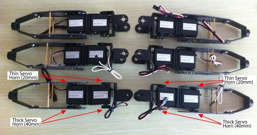
 to the north pole of the servo (with metal gear) and mount the thin servo horn (2mm) to the south pole of the servo.")
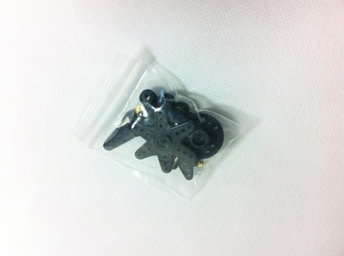
8 c) Side B: Set all the servos to their initial positions using our servo controller and the software (guidance to this part please refer to the electronics). Mount the thick servo horn (4mm) to the north pole of the servo (with metal gear) and mount the thin servo horn (2mm) to the south pole of the servo. Make sure the eight holes on horn positioned as the picture shown. Do not apply the screw yet. *If you are unable to perfect the horn position, you can always fine tune the initial position of the servo which I will introduce in the Fine Tune part of this guide.


9 d) Attach the knee joints to the butt area. First tight the north pole of the servo using M2*6 self-tapping screw and then tight the south pole of the servo using M2*5 self-tapping screw.


10 e) Side A: Set servos to initial positions. Mount the servo horns. Make sure the eight holes on horn positioned as the picture shown. f) Attach the lower leg area to side A. The holes on leg panels should match the holes on horns as the picture shown. Screw tight with M3 self-tapping screws. Repeat *5.

11
 Loose the screws inside the PS2 signal receiver.")

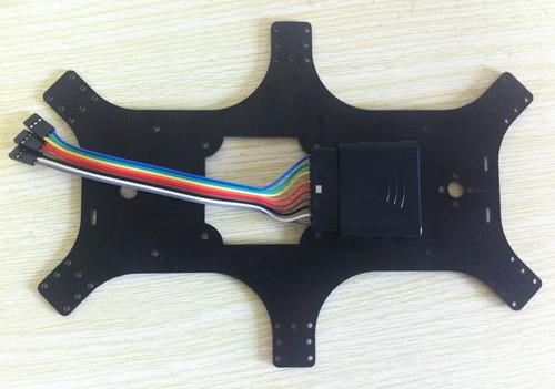
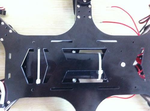
12 The Main Body a) Pick out the upper body panel and lower body panel. b) Loose the screws inside the PS2 signal receiver. c) Attach the signal receiver to the upper body panel using four M2*10 self-tapping screws. (You can find them in the horn accessory package) The picture below shows the front and back of the finished pattern.
13
 Get rid of the middle pins of the voltage reducer.")
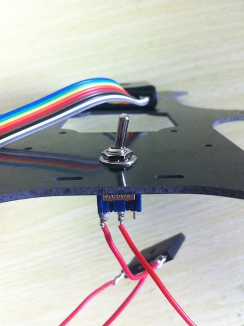
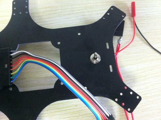
14 d) Pick out the power switch, voltage reducer, battery connecting wire, and the extra line of wire. e) Get rid of the middle pins of the voltage reducer. f) Cut the wire into three parts with individual length being 15cm,15cm,7cm


15 g) Solder the wires as the picture shown.
 Mount the power switch into the round hole of upper")
16 h) Connect the wires as the picture shown. i) Mount the power switch into the round hole of upper body panel.
17


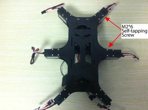
18 j) Attach six servos on the upper panel and tight with M2*6. The north pole of the servo is facing up as the picture shown.


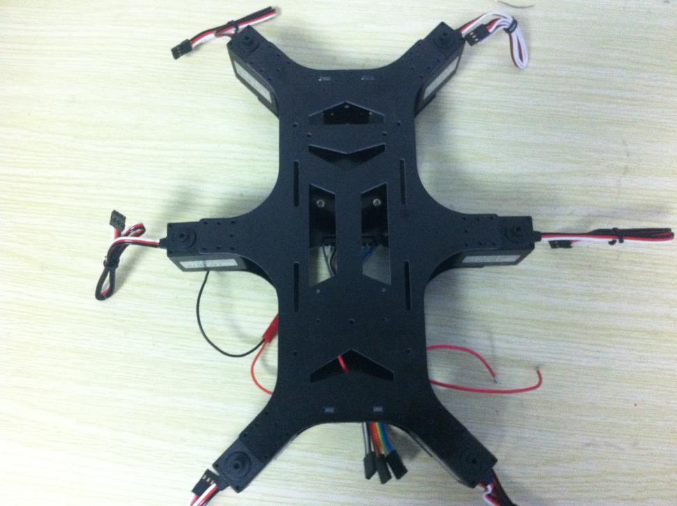
19 k) Pick out the support panel and attach them into the upper body panel. l) Attach the lower body panel and screw tight with M2*6.
20


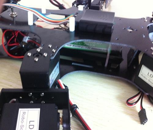
21 m) Attach the voltage reducer onto the lower body panel using M3*10 screw and nut as the picture shown.


22 n) Initialize the positions of the servos mounting on body panels and mount the horns onto the servos. As always, holes on the horns should position as the picture shown.
 Attach four nylon")

23 o) Attach the legs. p) Attach four nylon pillars onto the upper body panel with M3 nuts.


24 q) Fasten the LiPo battery onto the lower body panel using zipties.
25


26 r) Mount the servo controller and wire the servos and battery onto the board. Attach the servo wire extender to the farest servo of each leg.


27 s) Apply M3*6 screw to the north pole of each servo and M3*6 self-tapping screw to the south pole.
 As you probably know this is the wiring up of power supply.")
28 The Electronics Lobot 32 Channel Servo Controller Board a) Various ports explained. b) As you probably know this is the wiring up of power supply. The red dupont connector obviously connects to the battery.


29 c) Remote control set up. Wiring up the PS2 signal receiver to its port as the pictures describe. d) Switch the control mode to PS2. And turn on the power of PS2 joystick and you can start running the action groups remotely.
 Select the COM that your board connects to your computer and hit Connect. The default speed is 115200.")
30 The Software Lobot Servo Controller.exe a) Install the Driver b) Open up USB Control.exe. This servo controller can control up to 32 servos simultaneously. c) Select the COM that your board connects to your computer and hit Connect. The default speed is

31 d) The upper panel displays the selection status of servos. You can manually select or deselect the servos that connect to your servo board. Click the select bottom right next to the black area will select or deselect ALL the servos. The save bottom allows you to save your servo position.(must save under the same folder of USB Control.exe). And there are multiple language options under the language dropdown menu. e) The middle panel displays all the selected servos. You can drag and drop each servo on the displaying area, which allows you to mimic the real servo position. The slider on each window controls the rotation of individual servo. The P value represents servo position, with 500

32 being 0 degree and 1500 being 180 degree. The B value represents servo deviation. f) The upper right panel is where to download the action groups to the board. The Action group dropdown menu allows you to select one specific action group. The Start Address is where the specific action group takes place on the board. Think of the address as storage space. An action group that starts from 256 to 258 takes 3 address, this is equivalent of occupying 3 units of storage space of the board. Initialize allows you to start from Action Group No.0 Address 256, which is the starting point of storage space. Download is the most important bottom of this software. Hit this bottom and you will download the action groups you program into the board. Erase allows you to get rid of the downloaded action group. Hit Action Group bottom and the action group will run automatically. Select Only and the action group will play only once.

33 g) The lower right panel is where to create action groups. I will explain this part by an example. Say you want to create an action group of servo 1 rotating from 90 degree to 180 degree and back to 0 degree. 90 degree is the initial position of the servo and also the starting position of the action group. 1. So the first bottom to hit is the ResetServo bottom. This bottom will initialize the position of all selected servos which in the example, is servo Clicking Add will register the current servo position in the sequence of action groups which will appear on the bottom left panel. The initial position will be sequence Drag the slide to P value of 2500, which is 180 degree and hit Add again. This will register a second servo position which will be sequence 2.
34 4. Drag the slide to P value of 500, which is 0 degree and hit Add one more time. This will register a third servo position which will be sequence Hit Run. And the servo will run through sequence 1 to sequence 3. Now an action group is created. 6. You can modify the execution time of each action (sequence 1-sequence 2) with 1000 being 1 second. The lowest number is 100, which is 0.1 second. PS2 Joystick Control Code START Action Group 0 UP Action Group 1 DOWN Action Group 2 LEFT Action Group 3 RIGHT Action Group 4 Action Group 5 Action Group 6 Action Group 7 O Action Group 8 O
35 L1 Action Group 9 R1 Action Group 10 SELECT+ Action Group 11 Select first then SELECT+ Action Group 12 Select first then SELECT+ Action Group 13 Select first then SELECT+O Action Group 14 Select first then O SELECT+L1 Action Group 15 Select first then L1 SELECT+R1 Action Group 16 Select first then R1 L2 Speed Up R2 Speed Down
Assembly Guide Robokits India
 Robotic Arm 5 DOF Assembly Guide Robokits India info@robokits.co.in Robokits World http://www.robokitsworld.com http://www.robokitsworld.com Page 1 Overview : 5 DOF Robotic Arm from Robokits is a robotic
User Manual of Alpha 1s for Mac
 User Manual of Alpha 1s for Mac Version... 4 System Requirements... 4 Software Operation... 4 Access... 4 Install... 5 Connect to/disconnect from Robot... 5 Connect:... 5 Disconnect:... 5 Edit Actions...
1. ASSEMBLING THE PCB 2. FLASH THE ZIP LEDs 3. BUILDING THE WHEELS
 V1.0 :MOVE The Kitronik :MOVE mini for the BBC micro:bit provides an introduction to robotics. The :MOVE mini is a 2 wheeled robot, suitable for both remote control and autonomous operation. A range of
Bipedinno. 12-DOF Waist-high Robot
 Bipedinno 12-DOF Waist-high Robot Instruction Manual Version 1.18 Trademark Innovati,, and BASIC Commander, are registered trademarks of Innovati Inc. InnoBASIC and cmdbus are trademarks of Innovati Inc.
INSTRUCTION MANUAL. In vivo Test Apparatus for 305B Muscle Lever Systems
 INSTRUCTION MANUAL Model 806A In vivo Test Apparatus for 305B Muscle Lever Systems May 18, 2005, Revision 3 Copyright 2005 Aurora Scientific Inc. Aurora Scientific Inc. 360 Industrial Parkway S., Unit
Please note that Robots can move without warning, wear eye protection at all times and never touch a powered robot!
 Safety First! Updated: 18-Aug-2008 Safety First! Read and understand the documentation associated with any of the tools used in the assembly of these kits. Work in a clean, well-lit environment. Work slowly
Servo Animator version Table of contents
 Table of contents Getting Started.................................................. 2 Animating using a sound file........................................ 3 The Interface...................................................
The Derby Magic Company Track Assembly Instructions, revision E page 1 of 12
 The Derby Magic Company Track Assembly Instructions, revision E page 1 of 12 Thank you for purchasing a Derby Magic Pinewood Derby Track. To assemble your track, start with the stand. The parts of the
DIY KITS FRAME KIT. Thank you for purchasing a 3DR Y6 DIY Kit!
 DIY KITS Y6 FRAME KIT Thank you for purchasing a 3DR Y6 DIY Kit! These instructions will guide you through assembling and wiring your new autonomous multicopter. CONTENTS Your 3DR Y6 Kit contains: 35 mm
Range height adjustable assembly
 Table of contents Digital handset operation 3 Height adjustable bench kit 4-5 Cable carrier 6 Ganging tray and ganging rail 7 Height adjustable return frame kit 8 Cable entry pole 9 24 and 30 d worksurfaces
Assembly Guide for Printrbot - Simple Maker s Edition 1405
 Assembly Guide for Printrbot - Simple Maker s Edition 1405 Last update: March 2016 Please Note: be careful on the steps that are underlined 1 Contents Tools Needed:... 3 First step: Check components and
ORTOP Modular Robot v3.0 Arm Assembly
 Base Plate Assembly Parts Needed: Arm Assembly BAG 1 2 Socket Head Cap Screw, 1-1/4" 2 Socket Head Cap Screw, 1/2" 2 Button Head Cap Screw, 3/8" 6 Nuts 1 Gear Hub Spacer 1 Flat Building Plate 1 Single
The Derby Magic Company Track Assembly Instructions, revision F page 1 of 13
 The Derby Magic Company Track Assembly Instructions, revision F page 1 of 13 Thank you for purchasing a Derby Magic Pinewood Derby Track. To assemble your track, start with the stand. The parts of the
Google Pixel DISASSEMBLE. PennEngineering
 Google Pixel DISASSEMBLE June 4th, 2018 Allen Wang PennEngineering www.pemnet.com 1 Google Pixel Teardown www.pemnet.com 2 Details & Findings Pictures and Description of the Google Pixel and our disassembly
Assembly Instructions 10 X 10 Aluminum Roof Support
 Assembly Instructions 10 X 10 Aluminum Roof Support Aluminum Roof Support Bolt Package 16-5/16 X 2 ¼ SS Bolt 24-5/16 X 1 SS Bolt 40-5/16 SS Nylon Lock Nuts 16-5/16 SS Flat Washers 28-4 ½ Wood Screws 36-1
meped v2 Assembly Manual
 meped v Assembly Manual The meped is an open source quadruped robot designed by Scott Pierce of Spierce Technologies, LLC. This design is released under the Creative Commons, By Attribution, Share Alike
MAKEBLOCK MUSIC ROBOT KIT V2.0
 MAKEBLOCK MUSIC ROBOT KIT V2.0 Catalog Music Robot Kit V2.0 Introduction... 1 1 What is Music Robot Kit V2.0?... 1 1.1 Mechanical part... 1 1.2 Electronic part... 1 1.3 Software part... 1 2 Music Robot
The Derby Magic Company Track Assembly Instructions, revision D page 1 of 10
 The Derby Magic Company Track Assembly Instructions, revision D page 1 of 10 Thank you for purchasing a Derby Magic Pinewood Derby Track. To assemble your track, start with the stand. The parts of the
Mini Hexapodinno. 18-DOF Robot
 Mini Hexapodinno 18-DOF Robot Instruction Manual Version 1.11 Trademark Innovati,, and BASIC Commander, are registered trademarks of Innovati Inc. InnoBASIC and cmdbus are trademarks of Innovati Inc. Copyright
Strata. urniture. Adriana Instructions. Parts in the Arm Box: Parts in the Body Box: Watch our assembly videos at
 1A Watch our assembly videos at www.strataf.com/videos Parts in the Arm Box: Arm - Outside View Arm - Inside View 1B Parts in the Body Box: Back Deck x 1 Seat Deck x 1 with the Feet attached Back Panel
ScaleRCHelis.com V Light Controller Kit
 Thank you for purchasing the ScaleRCHelis.com V1.1 450 Light Controller Kit. This is something you can build in under a hour with some simple soldering equipment. Your kit will include all the parts necessary
RANGE DIGITAL HANDSET OPERATION. 1. Panel. 2. Initialization Procedure. 3. Move Up & Down. 4. Set Memory Positions. 5. Move to the Memorized Positions
 INSTRUCTION SHEET #2577INS PART #1730534 DIGITAL HANDSET OPERATION OPERATION INSTRUCTIONS 1. Panel 1 Button: Preset 1 2 Button: Preset 2 3 Button: Preset 3 S Button: Select Display: Reads in 1 / 2 " Increments
Issue No: MG025 Date: 05 June McMurdo SmartFind R5 GMDSS Radio IMO MSC. 1/Circ Update procedure
 Installation SERVICE BULLETIN Issue No: MG025 Date: 05 June 2017 McMurdo SmartFind R5 GMDSS Radio IMO MSC. 1/Circ. 1460 Update procedure Product Affected: McMurdo R5 GMDSS VHF Handheld Radio Reason: Compliance
StenBOT Robot Kit. Stensat Group LLC, Copyright 2018
 StenBOT Robot Kit 1 Stensat Group LLC, Copyright 2018 Legal Stuff Stensat Group LLC assumes no responsibility and/or liability for the use of the kit and documentation. There is a 90 day warranty for the
Preface. If you have any TECHNICAL questions, add a topic under FORUM section on our website and we'll reply as soon as possible.
 Preface About SunFounder SunFounder is a technology company focused on Raspberry Pi and Arduino open source community development. Committed to the promotion of open source culture, we strive to bring
BandMaster V Manual. Installation
 BandMaster V Manual Installation Installing and configuring the BM-5 BandMaster V is a simple process. All the configuration process is done from the front panel. Installation and configuration steps are
A59 APD & A86 CPD 5'X 16' SW ALUMINUM PORTA-DOCK
 Page 1 of 5 PORTA-DOCK, INC. A59 APD & A86 CPD 5'X 16' SW ALUMINUM PORTA-DOCK *For Beige Decking Add the Letter B to model* Thank you for purchasing our product! *Please read these instructions and follow
MGL Avionics Autopilot. Servo. Specifications & Installation Manual. Last Update: 20 October Disclaimer:
 MGL Avionics Autopilot Servo Specifications & Installation Manual Last Update: 20 October 2010 Disclaimer: MGL Avionics should not be held responsible for errors or omissions in this document. Usage of
S48-L12-SC AND G48-L12-GC STEEL PORTA-DOCK S82 SC 6 X 12 PLATFORM AND G82 GC 6 X 12 PLATFORM
 PAGE 1 OF 6 PORTA-DOCK, INC. S48-L12-SC AND G48-L12-GC STEEL PORTA-DOCK S82 SC 6 X 12 PLATFORM AND G82 GC 6 X 12 PLATFORM Thank you for purchasing our product! *Please read these instructions and follow
TOYOTA TACOMA BED EXTENDER Preparation. Part Number: PT
 Preparation Part Number: PT392-35120 Kit Contents 1 1 Curved Tube Assembly - Right 2 1 Curved Tube Assembly - Left 3 3 Center Tube 4 1 Hardware Bag 5 1 Installation Instructions 6 1 Care Card Hardware
Thank you for purchasing out product! *Please read these instructions and follow them step by step. *
 Page 1 of 7 AD17 AA DS 4 X 16 T12 Thank you for purchasing out product! *Please read these instructions and follow them step by step. * STEP 1. Slide two support posts (REF. # 24) into the two outside
Basic Installation HOFFMANN KEY HOFFMANN KEY. Page Revised: DEC. 2017
 Basic Installation Frame Assembly If you received the shutter disassembled, you will first have to assemble the frame. All frames are routed to accept a Hoffmann Key. Position the four frame pieces face
The Robot Program Episode 002: Building JD
 www.ez-robot.com The Robot Program Episode 002: Building JD This lesson will demonstrate how to build the [b]revolution JD[/b] robot. Follow along with [b]the Robot Program Episode 002: Building JD[/b].
Activity 2 Wave the Flag. Student Guide. Activity Overview. Robotics Jargon. Materials Needed. Building the Robot
 Activity Overview In this activity, you will learn about pivot points and integrate a servo motor into your robot to create a pivot point capable of waving a flag. After building the robot, you will conduct
The Torxis Linear Servo meets the following environmental conditions:
 Page: 1 1. PRODUCT DESCRIPTION The Torxis Linear Servo is the second generation of linear servos provided by GearWurx. This product features internal position sensing, and closed loop position control.
Budget Robotics Octabot Assembly Instructions
 Budget Robotics Octabot Assembly Instructions The Budget Robotics Octabot kit is a low-cost 7" diameter servo-driven robot base, ready for expansion. Assembly is simple, and takes less than 15 minutes.
Sketch-Up Guide for Woodworkers
 W Enjoy this selection from Sketch-Up Guide for Woodworkers In just seconds, you can enjoy this ebook of Sketch-Up Guide for Woodworkers. SketchUp Guide for BUY NOW! Google See how our magazine makes you
Micro Wizard Instructions
 How to install FAST TRACK K3 4-digit actual times and 1-digit sequence of finish display timer with Computer Serial Interface Enclosed you will find the Fast Track finish line, AC adapter and remote start
3DOF Leg Kit Assembly Guide VERSION 1.0
 3DOF Leg Kit Assembly Guide VERSION 1.0 WARRANTY CrustCrawler warrants its products against defects in materials and workmanship for a period of 30 days. If you discover a defect, CrustCrawler will, at
Arducopter 3DR-B Hardware
 Arducopter 3DR-B Thank you for purchasing an Arducopter 3DR kit. The Arducopter 3DR is a stable and supported quadrotor frame in the ongoing development of the Arducopter code on DIYDrones. It features
Code Product Qty 1 Top Vertex 3 2 Hot End Housing 1 3 Bottom Vertex 3 4 Print Platform Lock 3 5 End Stop Holder 3 6 Filament Feeder Motor Bracket 1 7
 List of Parts Code Product Qty 1 680mm Extrusion 3 2 Power Supply 1 3 240mm Extrusion 9 4 42mm Nema 17 Stepper Motor 3 5 Slider-Hotend Connecting Rod 6 6 48mm Nema 17 Stepper Motor 1 7 Linear Rail with
Using the 9XR Pro for More than Eight Channels
 Appendix B Using the 9XR Pro for More than Eight Channels Introduction In stock form, with a module such as the FrSky DJT or OrangeRx DSMX/DSM2 installed, the Turnigy 9XR Pro transmitter can control a
TOYOTA TACOMA BED EXTENDER Preparation. Part Number: PT General Applicability All 2012 and newer Tacoma models
 Preparation Part Number: PT392-35120 Kit Contents 1 1 Curved Tube Assembly - Right 2 1 Curved Tube Assembly - Left 3 3 Center Tube 4 1 Hardware Bag 5 1 Installation Instructions 6 1 Care Card Hardware
Instruction Guide TV Floor/ Trolley Flat Panel Electric
 Instruction Guide TV Floor/ Trolley FP1M- FP1MA- Flat Panel Electric Accessories Please note: If you have received a paper copy of the instruction guide we urge you to log onto www.trolleydollies.com.au
9 X 12 REMOVABLE TYPE ALUMINUM WINDOW BARS INSTALLATION INSTRUCTIONS Import Note : 9 X 12 Spacing Removable Type Installation is covered in this
 Import Note : 9 X 12 Spacing Removable Type Installation is covered in this Instruction. Removable Bars Only Mount in Recess Position ( Between Window Jamb/ Frame ) The horizontal bars spacing are 12 The
LANDING GEAR. 1. Fit landing gear into slots on bottom of fuselage.
 LANDING GEAR 1. Fit landing gear into slots on bottom of fuselage. 4. Use channel-lock pliers to press blind nuts into position (note: drilled hole should be slightly smaller than shaft of blind nut for
WARNING: Prior to installation, turn the power off to the vending machine and unplug it from its power source. Also, make sure to level the machine.
 Installation of Gum and Mint Tray for National 147, 157, 167 Important Note: Please read all instructions thoroughly before continuing with installation of kit. If you are having problems installing the
AX1001. Smith/Functional training Combo-free weight ASSEMBLY INSTRUCTIONS
 AX1001 Smith/Functional training Combo-free weight ASSEMBLY INSTRUCTIONS EXPLODED DIAGRAM 83 84 84 85/86 87 87 88 89 90 91 62 64 64 64 64 64 64 65 65 65 65 66 66 65 66 66 65 63 63 66 67 68 55 66 66 70
3DR ArduCopter Quad-C
 3DR ArduCopter Quad-C 3DR ArduCopter Quad-C Thank you for purchasing a 3DR ArduCopter Quad kit. The 3DR ArduCopter Quad is a stable and supported multi-rotor frame in the ongoing development of the ArduCopter
Servo board bit machine software use: QSC32 Servo controller front. QSC32 Servo controller back
 Servo board bit machine software use: QSC32 Servo controller front QSC32 Servo controller back QSC32E Servo controller illustrations 1, install the driver Using MINI-USB cable to connect the Servo board
Ribcage Installation. Part 2 - Assembly. Back-Bone V1.06
 Ribcage Installation Part 2 - Assembly Back-Bone V1.06 Contents Section 1 Before You Get Started... 2 Included With Your Kit:... 2 Figure: A... 3 CAUTION!... 4 Note:... 4 Tools Required... 5 Section 2:
Uniden CB Radio PRO 510XL (87-18 Wrangler YJ, TJ, JK & JL)
") Installation Time: 60-90 Minutes Tools Required: Phillips Screw Driver Drill (with drill bit set) Multimeter Tester Electrician s Stripper/Cutter Uniden CB Radio PRO 510XL (87-18 Wrangler YJ, TJ, JK &
Installation Time: 60-90 Minutes Tools Required: Phillips Screw Driver Drill (with drill bit set) Multimeter Tester Electrician s Stripper/Cutter Uniden CB Radio PRO 510XL (87-18 Wrangler YJ, TJ, JK &
set of safety brace steel cable draw-up gate kpl
 0324101 7108020 8208100 Order-nr. Description Number 0324101 safety brace steel cable draw-up gate 2 7108020 hexagon-head tap bolt M8x20 galv. 2 8208100 hexagon nut M8 galv. 2 set of safety brace steel
Apple iphone 8. PennEngineering
 Apple iphone 8 March 2018 by Jon Brunk PennEngineering www.pemnet.com 1 Apple iphone 8 www.pemnet.com 2 Details & Findings Pictures and Description of the iphone 8 and our disassembly process. www.pemnet.com
GRAND PIANO HARDWARE AND ACCESSORIES
 GRAND PIANO HARDWARE AND ACCESSORIES LID SUPPORT CUP No. 938 - Solid brass. Each No. 938N - Nickel plated. Each GRAND RAIL PROP NUTS Slotted grand rail prop nuts for replacement. Solid Brass. No. 925 -
PORTA-DOCK, INC. AP17 APD DS 4 X 16 T12 AW17 CPD DS 4 X 16 T12
 Page 1 of 7 PORTA-DOCK, INC. AP17 APD DS 4 X 16 T12 AW17 CPD DS 4 X 16 T12 *For Beige Decking Add the Letter B to Model* Thank you for purchasing out product! *Please read these instructions and follow
Handout Activity: HA043
 Handout Activity: HA043 Student/Intern information: Name Date Class Summary There are many different fasteners used in automotive applications, including screws, bolts, studs & nuts. Washers & chemical
Vinyl Cutter Instruction Manual
 Vinyl Cutter Instruction Manual 1 Product Inventory Inventory Here is a list of items you will receive with your vinyl cutter: Product components (Fig.1-4): 1x Cutter head unit complete with motor, plastic
Electric Skein Winder
 Electric Skein Winder Assembly and Use Package Contents 1 - Triangular Body (w/ motor) 1 - Cross Arm 1 - Left Foot (w/ yarn guide) 1 - Right Foot 1 - Adjustable Finger (w/ yarn clip) 3 - Adjustable Fingers
FORZA 700 SPEED Supplemental manual
 The FORZA 700 has evolved into a Speed Monster. The finely honed form minimizes air resistance, and the forward tilting rotor head helps transform all available power into speed. Fly beyond limits with
Ford Raptor Venom Front Bumper Installation Instructions
 PREPARATION 2010 2014 Ford Raptor Venom Front Bumper Installation Instructions 1. Disconnect the negative terminal on the battery. Park the vehicle on level ground and set the emergency brake. 2. We recommend
DMMDRV Software User Manual. Version: A10 50 / December 2015 Manual Code: DSFEN A
 DMMDRV Software User Manual Version: A10 50 / December 2015 Manual Code: DSFEN A1050 1215 Contents Section 1. General Software Safety Precautions 1.1 DYN2 System Safety 1.2 DYN4 System Safety 1.3 Servo
Robodyssey Mini Roach
 Robodyssey Mini Roach Assembly Instructions Version 1.1 Robodyssey Systems, LLC. Phone/Fax: 609-585-8535 20 Quimby Avenue Web: www.robodyssey.com Trenton, New Jersey 08610 Email: info@robodyssey.com Copright
Dura-Lock Roof System
 DLR-14 Dura-Lock Roof System Assembly and Installation Instructions Read the instructions before starting the job. They explain the steps required to produce a finished product that will meet factory specifications.
IN 578. Tools Required. Torque Specification: 10mm Socket 7/16 Socket 1/2 Socket 1/2 Wrench 7/16 Wrench 1/8 Allen Wrench.
 Tools Required 2011-C Ford F250/F350 No Drilling into Vehicle is Required 10mm Socket 7/16 Socket 1/2 Socket 1/2 Wrench 7/16 Wrench 1/8 Allen Wrench FL277 x 1 Torque Specification: 1/4 Bolts - 6 Ft Lbs.
FILE // 4 GAUGE TERMINAL CONNECTORS DOCUMENT
 04 July, 2018 FILE // 4 GAUGE TERMINAL CONNECTORS DOCUMENT Document Filetype: PDF 293 KB 0 FILE // 4 GAUGE TERMINAL CONNECTORS DOCUMENT Alibaba.com offers 124 4 gauge wire connectors products. Unique Bargains
OpenROV. Guide 3 - Electronics. We will now move to the assembly of the electronics that will control the ROV. Written By: OpenROV
 OpenROV Guide 3 - Electronics We will now move to the assembly of the electronics that will control the ROV. Written By: OpenROV 2017 openrov.dozuki.com Page 1 of 33 INTRODUCTION We will introduce soldering
INSTALLATION. For more information on this product or to order samples call or visit our website at builddirect.com.
 Page 1 Page 2 Page 3 Page 4 Page 5 1. Door Assembly: Step A: Attach part #34 to part #35 with screws #65/67. Step B & C: Attach part# 34.35(36) to part #33 with two #70 screws. Step D: Insert door bottom
Analog Discovery Arbitrary Function Generator for Windows 7 by Mr. David Fritz and Ms. Ellen Robertson
 Analog Discovery Arbitrary Function Generator for Windows 7 by Mr. David Fritz and Ms. Ellen Robertson Financial support to develop this tutorial was provided by the Bradley Department of Electrical and
FIRST Robotics Control System
 2018/2019 FIRST Robotics Control System Team 236 1 (click on a component to go to its slide) 2 The Robot Powered solely by 12V battery RoboRIO- is the computer on the robot Controlled by Java code on the
MOTOR & BULK HEAD. A Manual for Repair and Maintenance Technicians
 MOTOR & BULK HEAD A Manual for Repair and Maintenance Technicians CAUTION This manual is designed to help technicians who are already experienced in workshop procedures and know how to handle tools. Only
Copyright MLCS 1
 Copyright 2007. MLCS 1 WORKING WITH BOX JOINTS Box joints (AKA "Finger Joints") provide a simple, yet equally effective, alternative to dovetail joinery. In particular, they serve well for applications
INSTRUCTIONS. 3DR Plane CONTENTS. Thank you for purchasing a 3DR Plane!
 DR Plane INSTRUCTIONS Thank you for purchasing a DR Plane! CONTENTS 1 1 Fuselage Right wing Left wing Horizontal stabilizer Vertical stabilizer Carbon fiber bar 1 1 1 7 8 10 11 1 Audio/video (AV) cable
SC16A SERVO CONTROLLER
 SC16A SERVO CONTROLLER User s Manual V2.0 September 2008 Information contained in this publication regarding device applications and the like is intended through suggestion only and may be superseded by
DMMDRV 2017 Software User Manual. Version: A1324 / December 2017 Manual Code: DSFEN A
 DMMDRV 2017 Software User Manual Version: A1324 / December 2017 Manual Code: DSFEN A1324 1217 Contents Section 1. General Software Safety Precautions 1.1 DYN2 System Safety 1.2 DYN4 System Safety 1.3 Servo
1431 DOOR CLOSER WITH STANDARD DUTY ARMS (WITHOUT HOLD OPEN) INSTALLATION INSTRUCTIONS 1431 SERIES ADJUSTABLE FROM SIZE 1 THRU 6
 INSTALLATION INSTRUCTIONS 1431 SERIES ADJUSTABLE FROM SIZE 1 THRU 6") 1431 DOOR CLOSER WITH STANDARD DUTY ARMS (WITHOUT HOLD OPEN) INSTALLATION INSTRUCTIONS 1431 SERIES ADJUSTABLE FROM SIZE 1 THRU 6 FOR INSTALLATION ASSISTANCE, CALL SARGENT AT 1-800-727-5477 www.sargentlock.com
1431 DOOR CLOSER WITH STANDARD DUTY ARMS (WITHOUT HOLD OPEN) INSTALLATION INSTRUCTIONS 1431 SERIES ADJUSTABLE FROM SIZE 1 THRU 6 FOR INSTALLATION ASSISTANCE, CALL SARGENT AT 1-800-727-5477 www.sargentlock.com
Height Limited Switch
 Height Limited Switch Manual version: 1.0 Content Introduction...3 How it works...3 Key features...3 Hardware...4 Motor cut-off settings...4 Specification...4 Using the RC HLS #1 module...5 Powering the
Setting Standards Connectors M 16
 Setting Standards Connectors M 16 inclusive 15 Product Overview 16 Housings page 18 Inserts page 22 Accessories page 29 Technical Data M 16 Control Signal Connectors Mechanical Data Housing Materials and
Kossel Rev B Build Guide V1.0
 Kossel Rev B Build Guide V1.0 1 Table of Contents: Step 1: BASE ASSEMBLY Gathering parts: Building the Corners and Base: Step 2: UPPER ASSEMBLY Building Upper: Step 3: VERTICAL RAIL INSTALLATION Building
Installation Tutorial
 Installation Tutorial 1. Remove the finger parts, if the film, tear off the surface of the film, the number of parts were 1 4 4 5 5 2. First assemble the big finger parts, use M2X3 screws, M2X6 copper
1. Line Follower Placing the Line Follower Electrical Wiring of Line Follower Source Code Example and Testing...
 CONTENTS 1. Line Follower... 2 1.1 Placing the Line Follower... 2 1.2 Electrical Wiring of Line Follower... 3 1.3 Source Code Example and Testing... 4 2. CMPS11 Compass... 5 2.1 Placing the Compass on
Preface. If you have any TECHNICAL questions, add a topic under FORUM section on our website and we'll reply as soon as possible.
 Preface About is a technology company focused on Raspberry Pi and Arduino open source community development. Committed to the promotion of open source culture, we strive to bring the fun of electronics
Instructions to build the Hexapod in plywood
 Instructions to build the Hexapod in plywood Author: Jørgen Vendorf Disclaimer The author can in no regards be held responsible for anything regarding this instruction, drawings or anything that goes wrong
Parts List. Robotic Arm segments ¼ inch screws Cable XBEE module or Wifi module
 Robotic Arm 1 Legal Stuff Stensat Group LLC assumes no responsibility and/or liability for the use of the kit and documentation. There is a 90 day warranty for the Sten-Bot kit against component defects.
 For Wallbed models: KING SIZE INSTRUCTION BOOKLET #C1 Watch step by step installation instructions at: https://www.wallbedsbywilding.com/wallbed-installation-studio-series/ WARNING! ALL MURPHY/WALLBED
Cable Tray Kit: - Cable Tray - Cable Tray Cover - Power Block Support (x2) Top Support Kit: (x2) - 2 Top Supports. Quantities are per bench
 Top Support Kit: (x2) - 2 Top Supports. Quantities are per bench") Parts Included (per back to back bench) Column Kit: (x2) - 1 LH & 1 RH Column - Control Box - Hand Switch Cable Tray Kit: - Cable Tray - Cable Tray Cover - Power Block Support (x2) Depth Support Kit: -
Parts Included (per back to back bench) Column Kit: (x2) - 1 LH & 1 RH Column - Control Box - Hand Switch Cable Tray Kit: - Cable Tray - Cable Tray Cover - Power Block Support (x2) Depth Support Kit: -
SENC 150. Cross Feed Installation... Mounting Information... Center reading head... First Steps...
 Cross Feed Y Axis on Right Hand Side Cross Feed Installation... * Supplied with encoder hardware M4 x 8mm SHSS Mounting block 1/4-20 x 1/2 SHSS (2) per block *1/4-20 x 1 BHCS (2) or 1/4-20 x 1-1/4 BHCS
Mounting and Alignment Overview
 CHAPTER 3 This chapter provides an overview of bridge mounting and antenna alignment. The following sections are included in this chapter: Mounting the Bridge, page 3-2 Mounting Hardware, page 3-2 Bridge
3,500/4,500lb. Vertical Cable Feighner Lift
 3,500/4,500lb. Vertical Cable Feighner Lift CAUTION - PUT SAFETY FIRST 1. Before attempting to install or operate this lift, study and fully understand the proper operating procedures and safety precautions
Strata. urniture. Addison Instructions. Parts in the Arm Box: Parts in the Body Box: Watch our assembly videos at
 1A Watch our assembly videos at www.strataf.com/videos.html Parts in the Arm Box: Arm - Outside View Arm - Inside View Corbels x 4 1B Parts in the Body Box: Back Deck x 1 Seat Deck x 1 Back Panel x 1 with
White Quail Auto Trap
 White Quail Auto Trap WARNING SAFETY, STORAGE & USE IF THE MAIN SPRING IS ATTACHED AND THE TRAP ARM IS IN THE 6 O CLOCK POSITION, THE TRAP IS ARMED AND EXTREME CAUTION IS REQUIRED. TO DISARM, TURN THE
FREE CLIMBER 4400 ASSEMBLY INSTRUCTIONS 27694B
 FREE CLIMBER 4400 ASSEMBLY INSTRUCTIONS 27694B 1 TOOLS REQUIRED: CLAW HAMMER KNIFE 1/2 WRENCH OR SOCKET 1. USE KNIFE TO REMOVE ALL PLASTIC STRAPS FROM AROUND PALLET AND CARTON. STRAP 2. USE CLAW HAMMER
Assembly and Installation Guide
 The Easy Hang Closet Solution SM Install Your elfa In An Instant. Enjoy The Benefits For A Lifetime. Basic Tools For elfa Assembly and Installation Level Hand or Power Drill Drill Bits 1/8", 3/8", 5/16"
 INSTRUCTION BOOKLET #C0 Watch step by step installation instructions at: https://www.wallbedsbywilding.com/wallbed-installation-studio-series/ WARNING! ALL MURPHY/WALLBED SYSTEMS CONTAIN STORED ENERGY.
ifeel Sensor USER GUIDE SUPPLEMENT
 ifeel Sensor USER GUIDE SUPPLEMENT Choose Your ifeel Sensor There are two versions of the ifeel Sensor: USB and Bluetooth. Read the section of the user guide that matches your sensor. IFEEL BLUETOOTH SENSOR
955 Industrial St NE, Pine City MN Telephone: / Fax #218 LARGE MULTI-SPEED BLOWER & FILTER BOX KIT
 955 Industrial St NE, Pine City MN 55063 Telephone: 320.629.6737 / Fax 320.629.3677 www.dakacorp.com #218 LARGE MULTI-SPEED BLOWER & FILTER BOX KIT INSTALLATION INSTRUCTIONS FOR DAKA FURNACES SECTION 1:
ALUMA-CLASSIC FENCE W1716 & W1720 INSTRUCTION MANUAL
 ALUMA-CLASSIC FENCE W1716 & W1720 INSTRUCTION MANUAL Phone: Phone: 1-360-734-3482 On-Line On-Line Technical Technical Support: Support: tech-support@woodstockint.com tech-support@shopfox.biz COPYRIGHT
Adafruit 16-channel PWM/Servo Shield
 Adafruit 16-channel PWM/Servo Shield Created by lady ada Last updated on 2017-06-29 07:25:45 PM UTC Guide Contents Guide Contents Overview Assembly Shield Connections Pins Used Connecting other I2C devices
mila-wall (Series100) General Operating Instructions page 1 of 15
 General Operating Instructions page 1 of 15") mila-wall (Series100) General Operating Instructions page 1 of 15 Step #1: Before setting up walls, lower adjustable leveling feet on each panel approximately 1". This will allow access to the threaded
mila-wall (Series100) General Operating Instructions page 1 of 15 Step #1: Before setting up walls, lower adjustable leveling feet on each panel approximately 1". This will allow access to the threaded