Preface. If you have any TECHNICAL questions, add a topic under FORUM section on our website and we'll reply as soon as possible.
|
|
|
- Patrick Lloyd
- 5 years ago
- Views:
Transcription
1 Preface About SunFounder SunFounder is a technology company focused on Raspberry Pi and Arduino open source community development. Committed to the promotion of open source culture, we strive to bring the fun of electronics making to people all around the world and enable everyone to be a maker. Our products include learning kits, development boards, robots, sensor modules and development tools. In addition to high quality products, SunFounder also offers video tutorials to help you build your own project. If you have interest in open source or making something cool, welcome to join us! Visit for more! About This Kit The Rollarm Kit for Arduino is designed for mass hobbyists to learn robot arm control. With the open source MCU Arduino UNO and a servo expansion board, the robot arm is easy to use and full of fun. You can control its four axes by the 4 potentiometers on the handle, as well as make them move on your computer. In addition, it can memorize the movements it's made and repeat again and again, making it a great tool for repeated tasks. In this book, you can learn the basics of how a mechanical arm works and how to make one piece by piece. For more information, please go to our website and find the tutorial under LEARN -> Get tutorials. Also video tutorials about the assembly and playing are provided under VIDEO -> Robot Kit -> DIY Control Robot Arm Kit for Arduino- Rollarm. Free Support If you have any TECHNICAL questions, add a topic under FORUM section on our website and we'll reply as soon as possible. For NON-TECH questions like order and shipment issues, please send an to service@sunfounder.com. You're also welcomed to share your projects on FORUM.
2 Contents 1. Introduction Overview Components List Acrylic Plates Connecting Components Electronic Components Tools Self-Provided Components How to Control Getting Started with Software Arduino Description Install Arduino IDE Resources Download Assembly Base Bottom Plate + Riband Base Bottom Plate + Battery Holder Base Bottom Plate + Circuit Board Base Bottom Plate + Base Fixing Plate Base Upper Plate + Servo Base Fixing Plate + Base Upper Plate Joint 1-Connecting Plate + Servo Rocker Arm Joint 1 Connecting Plate Base + Joint 1 Connecting Plate Joint 2 + Right Joint Plate Joint 1 Connecting Plate + Joint 2 Connecting Plate Joint 1 Connecting Plate Gripper Fixing Plate Gripper Driving Plate + Gripper Driven Plate Grippers + Gripper Fixing Plate Gripper Fixing Plate + Right Joint Plate Joint 2 Connecting Plate + Joint 3 Connecting Plate Left Joint Plate Handle Wiring Control the Rollarm Manual Control Automatic Control Code Explanation PC Control (by Labview) Installing Labview Software Running the Labview... 49

3 1. Introduction 1.1 Overview The Rollarm Kit is an interesting and useful learning tool for Arduino and robot hobbyists. With the acrylic design and code based on Arduino, it enables users to learn programming from easy to difficult, control the mechanical arm freely and perform various fun operations! This fun mechanical arm consists of 4 axes, each controlled by a servo. Powered by two batteries, the control systems is composed of SunFounder Uno board, servo extension board, and remote control board. The kit includes all necessary components like acrylic plates, circuit boards, and connector parts. For your better learning, installation and debugging video tutorials are provided on our website. Also you can download the user manual which elaborates on the installation procedures and program explanation. With these resources, you can quickly and effortlessly make creative projects with the Rollarm. Now let's go to get the fun! 1


4 2. Components List 2.1 Acrylic Plates Prior to assembling the Rollarm, you need to remove the residues in the holes of the plates and the stickers on the plates. Here we take the Joint 1 fixing plate for example. 1. Check whether there are some residues in the holes of the acrylic plate. 2. Use a tool with a pointed end to remove the residue. 2


5 3. Make sure that all the residues are cleared. 4. Use the pointed tool to scratch off the sticker on the plate. 2.2 Connecting Components Name Component Qty. M1.2*4 Self-tapping Screw 14 M2*8 Screw 8 M2 Nut 8 M3*8 Flat-Head Screw 2 M3*8 Screw 10 3


6 M3*10 Screw 18 M3 Nut 20 M7 Thin Nut 4 3*10*1 Washer 1 M3*10 Aluminum Tube 5 M3*6 Corn Rivet 2 φ3*φ8*4 Band Edge Bearing 3 4

")

7 2.3 Electronic Components Name Component Qty. SunFounder Servo (9g) 4 Potentiometer Button 4 Button *2 Battery Holder 1 5


8 SunFounder Mars Board 1 Expansion Board 1 Potentiometer Module 1 USB Type-C Cable 1 RJ11 Cable 2 Riband 1 6

9 3M Non-skid Pad 4 Heat Shrink Tubing 2 Cable Clip Tools Screw Driver Self-Provided Components Battery 2 7
10 3. How to Control 1. Install Arduino IDE 2. Assemble the Rollarm (Remember to configure the servos before assembly. Pay attention to the detailed operations) 3. Control with handle: download the Rollarm package and run the program (Indispensable step before operating the Rollarm) 4. Control with Labview: download the Labview to your PC and install for control (download is a must-do before subsequent operating) Let s get started. Enjoy! 4. Getting Started with Software 4.1 Arduino Description Arduino is an open source platform that applies simple software and hardware. You can get it in a short even when you know little of it. It provides an integrated development environment (IDE) for code editing and compiling, compatible with multiple control boards. So you can just download the Arduino IDE, upload the sketches (i.e. the code files) to the board, and then you can see experimental phenomena. For more information, refer to Install Arduino IDE The code in this kit is written based on Arduino, so you need to install the IDE first. Skip it if you have done this. Step 1: Go to the arduino.cc website and click Download. On the page, check the software list on the right side under Download the Arduino Software. 8


11 Find the one that suits your operation system and click to download. There are two versions of Arduino for Windows: Installer or ZIP file. You're recommended to download the former. Step 2: Double click the.exe file and the following window will show up. Click I Agree. The following interface will show up. Choose Next. 9


12 Click Browse to choose the installation path or enter a directory at the Destination Folder. Click Install. The following interface will show up. Note: After the installing progress bar goes to the end, the Close button may be enabled for some PC. Just click it to complete the installation. 10


13 Then a prompt appears. Select Always trust software for "Adafruit Industries" and click Install. Select Always trust software for "Arduino srl" and click Install. After the installation is done, click Close. Then an Arduino icon will appear on the desktop: 11
14 4.2 Resources Download 1. For downloading the program, go to LEARN->Get tutorials->robot Kit-> DIY Control Robot Arm kit for Arduino-Rollarm and download the package: 2. Downloading the Labview software The link for downloading (you may also find the link in the PDF file downloaded before): Note: Labview/Rollarm/Rollarm s Installer/setup.ex: The installer of Labview on your PC. Then choose your installation path. 3. For related introduction and installation videos of the DIY Control Robot Arm kit for Arduino-Rollarm, please click VIDEO -> Robot Kit -> DIY Control Robot Arm Kit for Arduino-Rollarm. 12


15 5. Assembly 5.1 Base Bottom Plate + Riband 1. Cut the 50cm ribbon into halves. Thread the ribbon through the Acrylic plate. Leave the riband with one end of a long part and the other of a short one. Thread another riband through the base bottom plate. 5.2 Base Bottom Plate + Battery Holder 1. Place the battery holder on the base bottom plate. Cling two M3 nuts underneath the plate and keep them aligned with the holes of the holder. Pay attention to put the end without holder power lines at the right side. 2. Insert two M3*10 flat-head screws into the nuts and fasten them with the screw driver. 13


16 3. Fold the ribbon in the battery holder. 4. Align the anode of the battery with that of the battery cover and so does the cathode. 5. Insert the battery into the battery holder. 5.3 Base Bottom Plate + Circuit Board 1. Align the four acrylic washers with the holes of the base bottom plate (a spare washed is provided in case). 2. Place the four acrylic washers on the base bottom plate. 14


17 3. Align the acrylic washers and holes on the plate. Cling 4 M3 nuts to the holes underneath the plate. 4. Place the Mars board onto the plate with its holes aligned with the washers. Fasten them with the M3*12 screws. 5. Align the pin headers of the expansion board with the sockets of the Mars board. 6. Insert the pin headers into the sockets. 5.4 Base Bottom Plate + Base Fixing Plate 1. Put an M3 nut in the hole of the base fixing plate. Align its bulges with the holes of the base bottom plate. 2. Insert the bulges into the holes. Fix the two plates with the M3 nut and the M3*10 screw. 15

18 3. Mount the other base fixing plate in the same way. 5.5 Base Upper Plate + Servo 1. Align the servo with the slot of the base upper plate with the rotating axis close to the middle line of the base upper plate. 2. Insert the servo into the slot. 3. Hold an M2 nut underneath the hole of the servo and the upper plate and insert an M2*8 screw. 4. Fasten them with the screw driver. 5. Fasten the other screw and nut in the same way. 16


19 5.6 Base Fixing Plate + Base Upper Plate 1. Align the holes of the base upper plate with the bulges of the base fixing plate. 2. Insert the bulges into the holes. 3. Put an M3 nut in the hole of the base fixing plate, insert an M3*10 screw through the plate into the nut and fasten them with the screw driver. 4. Fasten the other screw in the same way. 5. Paste four non-skid pads onto the corners of the base bottom plate. 6. It will be like this after pasting. 17


20 5.7 Joint 1-Connecting Plate + Servo Rocker Arm 1. Align the servo rocker arm with the hole of the Joint 1-connecting plate. 2. Put the rocker arm on the connecting plate and rotate it to align its holes with those of the plate. 3. Align the holes like this: 4. Insert an M1.2*4 self-tapping screw into a hole of the plate through the rocker arm. 5. Fasten them with the screw driver. 6. Fasten the other self-tapping screws in the same way. 7. Fix a servo rocker arm on the Right Joint Plate 1 in the same way. 18


21 8. Likewise, fix a servo rocker arm on the Right Joint Plate Joint 1 Connecting Plate 1. Align the bulges of the Right Joint Plate 1 with the slots of the Joint 1 Connecting plate. 2. Insert the bulges into the slots. 3. Put an M3 nut into the hole of the Right Joint Plate 1 and insert an M3*10 screw into the nut through the connecting plate. 4. Fasten them with the screw driver. 19


22 5.9 Base + Joint 1 Connecting Plate Note: Before installing the rocker arms for each servo, you need to adjust the servo. Step 1: Insert the servo wires into D4, connect the Servo Control Board to the PC via the USB cable, and the PC will automatically install the driver. The COM port connected will appear. Connect the yellow, red, and brown wire to S, V, and G port as shown above. Step 2: Connect the Rollarm to your computer with the Type-C cable: the driver will be installed automatically at that time, then you can see COMxx in device manager. Step 3: Go to the folder DIY Control Robot Arm kit for Arduino-Rollarm/Arduino Code /Servo and open the file Servo.ino. 20


23 Step 4: Select the Board. And Port. Step 5: Click Upload. 21


24 After the upload is completed successfully, unplug the USB cable and press the switch on the board. You may hear the sound of gear moving (or may not, if the servo shaft happens to be at 90 degrees at the beginning; but you GENTLY spin the rocker arm and you'll find it's unmovable). So now the servo is adjusted to 90 degrees. 1. Power on the servo: connect it to the Port 4 (with label) on the expansion board. Align the edge of the connecting plate with that of the base plate. 2. Install the servo rocker arm onto the shaft of the servo. 3. Fasten them with an M2*4 self-tapping screw. 4. It would be like this after fastening. 22


25 5.10 Joint 2 + Right Joint Plate 2 1. Align the servo with the right joint plate 2. Pay attention that the servo shaft should point to the plate end near the slot the servo to be placed in. 2. Insert the servo into the slot of the plate. 3. Put an M2 nut in the hole of the servo and insert an M2*8 screw into the nut and fasten them. 4. It will be like this after fastening. 5. Fasten the other screw in the same way. 6. Fix the other servo in the same way. 23


26 7. Align the bulges of the joint 2- connecting plate with the slots of the right joint plate Insert the bulges into the slots. 9. Put an M3 nut into the hole of the joint 2-connecting plate and insert an M3*10 screw into the nut. 10. Fasten them with the screwdriver. 11. Align the two M3*6 copper corn rivets with the holes of the left joint plate Insert the rivets into the holes of the plate. 24

27 13. Put an M3 nut in the hole of the joint 2- connecting plate. Align the bulges of the plate with the slots of the left joint plate Insert the bulges into the slots. 15. Insert an M3*10 screw into the nut and fasten them with the screw driver. 16. It will be like this after fastening. 25


28 5.11 Joint 1 Connecting Plate + Joint 2 Connecting Plate Note: Connect the servo of Joint 2 connecting plate to port D5 of the expansion board, while the servo of Joint 3 connecting plate to port D6. Power on the servos, then it will be rotate to its 90 position as shown below: 26


29 1. Power on the servo. Connect the servo of joint 2-connecting plate to the port 5 of the expansion board. Align the servo shaft with the round rocker arm connected to the joint 1- connecting plate. Remember the servo should be vertically placed as shown below. 2. Insert the shaft into rocker arm. 3. Fasten them with an M2*4 self-tapping screw. 4. It will be like this after fastening. 27


30 5.12 Joint 1 Connecting Plate 1. Align the band edge bearing with the corn rivet. Put the bearing into the rivet. 2. Move the bearing against the joint 2 connecting plate and align the hole of left joint 1 connecting plate with the bearing. 3. Insert the bulges of the left joint 1 into the slots of the joint 1-connecting plate and insert the bearing into the hole of the former. 4. Turn the power switch off. Rotate the joint 1-connecting plate 90 degrees clockwise. 28


31 5. Put an M3 nut in the hole of the left joint connecting plate 1 and insert an M3*10 screw into the nut and fasten them. 6. It will be like this after fastening Gripper Fixing Plate 1. Align the servo with the slot of the gripper fixing plate (pay attention to the direction of the shaft). 2. Insert the servo into the slot. 29


32 3. Put an M2 nut underneath the hole and hold it with your finger, and insert an M2*8 screw into the nut and fasten them. 4. It will be like this after fastening. 5. Fasten another screw in the same way Gripper Driving Plate + Gripper Driven Plate 1. Align the servo rocker arm with the hole of the gripper driving plate. Note: Pay attention to the side the rocker is on. 2. Put the rocker arm on the plate. 30

33 3. Insert an M1.2*4 self-tapping screw into the first hole of rocker arm. 4. Fasten them with the screw driver. 5. Insert an M1.2*4 self-tapping screw into the last hole and fasten them. 6. Align an M3*10 aluminum tube with the rest hole of the plate. 7. Put the tube on the plate. 8. Insert an M3*8 screw into the tube from the other side of the plate. 9. Fasten them with the screw driver. 10. Fix another aluminum tube similarly. 31


34 11. Align the holes of the gripper assistant with the aluminum tubes. 12. Fasten them with an M3*8 screw. 13. It would be like this after fastening. 14. Fix an M3*8 screw to the other tube. 15. Install the gripper driven plate in the same way. 32


35 5.15 Grippers + Gripper Fixing Plate Note: Connect the servo of the gripper fixing plate to the port D7 of the expansion board, then power on the servo, then the servo will rotate to its 170 position as shown below: 1. Power on the servo and connect the servo of the gripper fixing plate to port No.7 of the expansion board. Align the servo rocker arm with the shaft and keep the gripper edge of the driving plate parallel to the side of the fixing plate. 2. Insert the servo shaft into the rocker arm. 33


36 3. Fasten them with an M2*4 self-tapping screw. 4. It will be like this after fastening. 5. Align the aluminum tube with the hole of the gripper fixing plate. 6. Put the tube on the plate. 7. Insert an M3*8 screw into the hole. 8. Fasten them with the screw driver. 34


37 9. Align a band edge bearing with the aluminum tube with the edge against the tube. Put the gripper driven plate onto the bearing. 10. Keep the inner edges of the two gripper plates parallel and the gears meshed. 11. Put a 3*10*1 washer on the bearing and fasten them with an M3*8 screw. 12. It will be like this after fastening Gripper Fixing Plate + Right Joint Plate 3 1. Align the bulges of the gripper fixing plate with the slots of the right joint plate Insert the bulges into the slots. 35

38 3. Put an M3 nut in the hole of the gripper fixing plate and insert an M3*10 screw into the nut. 4. Fasten them with the screw driver Joint 2 Connecting Plate + Joint 3 Connecting Plate 1. Power on the servo and connect the servo of the joint 3 connecting plate to port No.6 of the expansion board. Align the servo rocker arm with the shaft and keep the two joint plates near perpendicular to each other. 2. Fasten them. 3. Fasten them with an M2*4 self-tapping screw. 4. It will be like this after fastening. 36


39 5.18 Left Joint Plate 3 1. Align the band edge bearing with the corn rivet with its edge against the plate. 2. Align the hole of the left joint plate 3 with the bearing. 3. Insert the bulges of the gripper fixing plate into the slots of the left joint plate Put an M3 nut in the hole of the fixing plate and insert an M3*10 screw into the nut. 37


40 5. Fasten them with the screw driver Handle 1. Align the bulges of the handle-fixing plate with the slotted holes of the handlebottom plate. 2. Insert the bulges into the slots. 3. Put an M3 nut in the hole of the fixing plate and insert an M3*10 screw into the nut. 4. Fasten them with the screw driver. 38


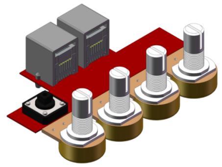
41 5. Fix the other handle fixing plate in the same way. 6. Align the four holes of the handle upper plate with the 4 potentiometers on the Potentiometer Module. 7. Insert the pots into the four holes. 8. Fasten one pot with an M7 thin nut. 9. It will be like this after fastening. 10. Fasten the other three pots with the M7 thin nuts in the same way. 39

42 11. Align the slotted holes of the handle upper plate with the bulges of the handle fixing plate. 12. Insert the bulges into the holes with the module on the bottom plate. 13. Put an M3 nut in the hole of the handle fixing plate and insert an M3*10 screw into the nut. 14. Fasten them with the screw driver. 15. Fasten the other screw similarly. 16. Rotate the potentiometer clockwise to the end, and align the bulged part of button with the 0 position 40


43 17. Put the button onto the potentiometer and press to tighten them. 18. Install the other three pot buttons in the same way. Rotate them to 0 position. 19. Install the button. 20. Press to tighten it. 41

44 5.20 Wiring In previous servos assembly, the servo 1, 2, 3, and four have been connected to the ports 4, 5, 6, and 7 of the extension board. Thus, we only need to connect port 1 and 2 of the handle to that of the extension board with the RJ11 cables. Notes: 1. Before connecting the servo wires to the ports, turn off the power. Turn it on again after all the wires are connected. 2. When the servos are on, remember NOT to rotate the servo rocker arms. Turn them off if you want to do so. 3. Please be careful that the servos shouldn t be kept stalling. Otherwise, it will cause damages. In a word, when you are not running the Rollarm, keep it OFF. 42


45 6. Control the Rollarm There are two ways to control the Rollarm: manual control (by handle), or PC control (by Labview). The detailed operations for two ways are as follows. 6.1 Manual Control Step 1: Run the Rollarm.ino file under the path DIY Control Robot Arm kit for Arduino- Rollarm\Arduino Code. There are four code files in Rollarm, and you need to doubleclick Rollarm to open the four simultaneously. Rollarm.ino is the main program, when the others are subprograms. When you open the main program, the subprograms will be opened automatically: Step 2: Select the corresponding board and port, then click Upload. Step 3: After the code upload, turn the power switch on, then we can try to control the Rollarm. Step 4: Rotate the four potentiometer buttons in different colors to try the controlled servo and direction: the white button to control the Servo 4, the yellow to Servo 3, the orange to Servo 2, and the red one to control Servo 1. 43

.")
46 6.2 Automatic Control With the handle, the Rollarm can record its behaviors: Rotate one potentiometer button to control one servo to the desired position, and press the yellow button shortly to let the control board record this step. Record the rest steps in this way. When all the steps are done, press and hold the yellow button for a while (3s). So it will repeat the recorded steps (Rollarm can record at most 100 steps because of the control board s memory limit). 44

47 Thus we can make it automatically carry blocks continuously: Code Explanation The program includes three parts: rotating the potentiometers to control the Rollarm, pressing the button slightly for less than one second to record Rollarm s behaviors and pressing the button for a relatively longer time to make Rollarm repeat the recorded steps. There are four potentiometers to control the arms. The 4 servos from top to bottom are connected to port 4-7 respectively of the expansion board, and the 4 potentiometers control the ports accordingly. In other words, spin the white potentiometer to control the uppermost servo, the yellow to control the next servo below, the orange to control the next servo, and the red one to control the bottom servo. Since the Rollarm has four servos acting as the moving joint, we need to include a header file for driving the servos and define them. // Create servo object to control a servo. #include <Servo.h> Servo Servo_0; Servo Servo_1; Servo Servo_2; 45
48 Servo Servo_3; After defining the function of driving the servos, we need to read the AD value of the potentiometers and convert it into the rotating angle of the servo since the servos are controlled by rotating the potentiometers. //Read the values ot the potentiometers. void ReadPot() { SensVal[0] = 0; SensVal[1] = 0; SensVal[2] = 0; SensVal[3] = 0; } SensVal[0] = analogread(a3); SensVal[1] = analogread(a2); SensVal[2] = analogread(a1); SensVal[3] = analogread(a0); //The value of the potentiometer is matched to the angle value. void Mapping0() { SensVal[0] = map(sensval[0], 0, 1023, 10, 170); SensVal[1] = map(sensval[1], 0, 1023, 10, 170); SensVal[2] = map(sensval[2], 0, 1023, 10, 170); SensVal[3] = map(sensval[3], 0, 1023, 100, 175); } After compiling the program, we need to make Rollarm remember the steps, which is done through pressing the button. //Calculate the time the button pressed void Button() { if (digitalread(3) == 0) { delay(10); if (digitalread(3) == 0) { KeyValue = 0; while (!digitalread(3)) { KeyValue++; delay(100); } } } } We can tell which part of the code the Rollarm is performing by reading the value upon pressing the button. When the value is larger than 10, it means Rollarm is repeating the steps. When it is between 0 and 10, it means Rollarm is remembering. And when it is 0, it means Rollarm is being controlled by the potentiometers. The specific program is as follows: //Check the button. static int Flag = 1; 46
49 Button(); //The time of pressing the button is not long then record the action. if ((KeyValue < 10) && (KeyValue > 0)) { KeyValue = 0; Record(); Mapping1(); } //Long press the button and open the auto mode,start repeating the action. else if (KeyValue > 10) { if (Flag == 1) { Flag = 0; Calculate(); } Drive_init(); delay(3000); for (int i = 1; i < Time; i++) { Drive_repeat(i); delay(500); } } //Did not press the button, open the manual mode. else { ReadPot(); Mapping0(); Next, we are going to call the function to write the value of the servo rotating angle. However, it is not merely about writing the values directly; the difference between two adjacent rotating values will also be written into the servos. Here we take a servo program for example. //The first axis. if (Dif0[n] > 0) { for (int j = Joint0[n - 1]; j <= Joint0[n]; j++) { Servo_0.write(j); delay(10); } } else { for (int j = Joint0[n - 1]; j >= Joint0[n]; j--) { Servo_0.write(j); delay(10); } } 47


50 6.4 PC Control (by Labview) Installing Labview Software For this kit, we use the Labview software for control on PC. If you have other better options, welcome to share by post under FORUM on our website Download the Labview package in the link below: After downloading, unzip and open it. If you haven t installed the Labview Runtime, you can get into the Labview\Rollarm Project\Rollarm Installer folder, install the setup file: If you have installed the Labview Runtime, you can just get into the Labview\Rollarm Project\Rollarm folder, double click the Rollarm file: The following interface will show up. 48
51 6.4.2 Running the Labview Before running the software on the computer, we should install a driving program into Arduino. Open the folder LIFA_Base under path DIY Control Robot Arm kit for Arduino- Rollarm\Arduino Code Open the file LIFA_Base.ino. Upload the sketch to the Arduino. DO NOT unplug the USB cable at the moment. Open the software, which includes two parts: manual control and automatic control. 1) Manual Mode 49
52 a) See the interface of manual control below. After the Labview is installed and run, this mode is enabled by default. b) Click the menu downlist icon for Serial Port, select the port according to your COM port. Here is COM1, which varies for different computers. The interface is as follows: 50
53 If such an icon appears before the port, it indicates something goes wrong with the port: To solve the problem, just replug the USB cable. Then start from sketch upload again. Select the Board Type and Connection Type, here we take Uno and USB connection type as an example: 51


54 c) There are three small icons at the top left. Click the middle one to run the software. Then the three icons will change to the state below: 52


55 The initial position of the four axes is respectively set to 90, 90, 90, and 150 from bottom to top, so the corresponding servos should be like as shown below: d) Click Start, and the button will change from dark to light green, as shown below: 53
 Automatic Mode You can also switch between manual control and automatic control through the rocker switch between Manual and Auto.")
56 You can move the slider on the window to control the Rollarm. On the right, there are 4 dashboards, 1, 2, 3 and 4, which correspond to the four servos respectively from bottom up. 2) Automatic Mode You can also switch between manual control and automatic control through the rocker switch between Manual and Auto. To switch to the automatic control, you need to click the Start button to disable it and the following interface will appear. Fill the value of the rotating angle of the servos into the table under Auto Mode one by one. 54

57 Enter the interval time below the table. The first interval time refers to the time between setting the rotating angles of two groups, each row considered as a group. Here the interval time on the left refers to the time between setting the rotating angle between M4 in row 1 and M2 in row 2 or M4 in row 2 and M1 in row 3...etc. The interval time on the right refers to the one between setting the two adjacent rotating angles within a group. After filling the figures, click the Start button. Rollarm will then perform as you just set. Note that the range of the data for Mode 4 is 90~180. Otherwise, it will be stuck and damaged. 55


58 FAQ 1) About the assembly: Q1: After assembly and program download, the Rollarm s four axes are in wired position, some may be out of control. What should I do? A: Remember to power on and calibrate each servo before assembly. Q2: When I mount the rocker arm, the acrylic plate cracks. A: When you fasten the rocker arm with the screws, do not over tighten them forcefully. 2) About the Arduino code control: Q1: When I open a program, it prompts me that a new folder should be created. After I click Yes and a new folder is created, the main program reports an error when I want to open the main program. What s going wrong? A1: DO NOT open these subprograms under Arduino Code\Rollarm separately: If you open the subprograms separately, a dialog box will pop up like this: If a new folder has been created for the subprogram, please cut the subprogram file to the original directory Arduino Code \Rollarm. Reopen the main program: 56
 About the Labview software control: Q1: After powering on the Rollarm, why do the servos shake a little when there's no movement at all? A: There may be something wrong with the Serial Port.")
59 Then you can see the subprograms have been opened too: 3) About the Labview software control: Q1: After powering on the Rollarm, why do the servos shake a little when there's no movement at all? A: There may be something wrong with the Serial Port. For instance, the following condition may appear: Turn off the Rollarm, power it on again, and reconnect the serial port to try. Q2: The Rollarm is in a strange position when I click Start and it's in the automatic mode. Anything wrong? A: Here no value is filled in the table yet. The first three axes are in 0, and the last one is in 90. You need to fill the correct value of the rotating angle first, and click Start to run. 57

60 Before clicking Start, you need to fill in the rotating angle for each axis in different steps, and the interval time between steps. If you don t know the exact angle, you can shift to the manual mode and note down the angle values for each step, and then shift back to fill in. When all the steps above are done, you can click Start to let Rollarm perform the automatic control. 58
61 Copyright Notice All contents including but not limited to texts, images, and code in this manual are owned by the SunFounder Company. You should only use it for personal study, investigation, enjoyment, or other non-commercial or nonprofit purposes, under the related regulations and copyrights laws, without infringing the legal rights of the author and relevant right holders. For any individual or organization that uses these for commercial profit without permission, the Company reserves the right to take legal action. 59
Preface. If you have any TECHNICAL questions, add a topic under FORUM section on our website and we'll reply as soon as possible.
 Preface About is a technology company focused on Raspberry Pi and Arduino open source community development. Committed to the promotion of open source culture, we strive to bring the fun of electronics
Content Components... 1 i. Acrylic Plates... 1 ii. Mechanical Fasteners... 3 iii. Electrical Components... 4 Introduction... 5 Getting Started... 6 Ar
 About r Preface r is a technology company focused on Raspberry Pi and Arduino open source community development. Committed to the promotion of open source culture, we strive to bring the fun of electronics
1. ASSEMBLING THE PCB 2. FLASH THE ZIP LEDs 3. BUILDING THE WHEELS
 V1.0 :MOVE The Kitronik :MOVE mini for the BBC micro:bit provides an introduction to robotics. The :MOVE mini is a 2 wheeled robot, suitable for both remote control and autonomous operation. A range of
StenBOT Robot Kit. Stensat Group LLC, Copyright 2018
 StenBOT Robot Kit 1 Stensat Group LLC, Copyright 2018 Legal Stuff Stensat Group LLC assumes no responsibility and/or liability for the use of the kit and documentation. There is a 90 day warranty for the
meped v2 Assembly Manual
 meped v Assembly Manual The meped is an open source quadruped robot designed by Scott Pierce of Spierce Technologies, LLC. This design is released under the Creative Commons, By Attribution, Share Alike
MAKEBLOCK MUSIC ROBOT KIT V2.0
 MAKEBLOCK MUSIC ROBOT KIT V2.0 Catalog Music Robot Kit V2.0 Introduction... 1 1 What is Music Robot Kit V2.0?... 1 1.1 Mechanical part... 1 1.2 Electronic part... 1 1.3 Software part... 1 2 Music Robot
Bipedinno. 12-DOF Waist-high Robot
 Bipedinno 12-DOF Waist-high Robot Instruction Manual Version 1.18 Trademark Innovati,, and BASIC Commander, are registered trademarks of Innovati Inc. InnoBASIC and cmdbus are trademarks of Innovati Inc.
smraza Getting Start Guide Contents Arduino IDE (Integrated Development Environment)... 1 Introduction... 1 Install the Arduino Software (IDE)...
... 1 Introduction... 1 Install the Arduino Software (IDE)...") Getting Start Guide Contents Arduino IDE (Integrated Development Environment)... 1 Introduction... 1 Install the Arduino Software (IDE)...1 Introduction... 1 Step 1: Get an Uno R3 and USB cable... 2 Step
Getting Start Guide Contents Arduino IDE (Integrated Development Environment)... 1 Introduction... 1 Install the Arduino Software (IDE)...1 Introduction... 1 Step 1: Get an Uno R3 and USB cable... 2 Step
Cable Tray Kit: - Cable Tray - Cable Tray Cover - Power Block Support (x2) Top Support Kit: (x2) - 2 Top Supports. Quantities are per bench
 Top Support Kit: (x2) - 2 Top Supports. Quantities are per bench") Parts Included (per back to back bench) Column Kit: (x2) - 1 LH & 1 RH Column - Control Box - Hand Switch Cable Tray Kit: - Cable Tray - Cable Tray Cover - Power Block Support (x2) Depth Support Kit: -
Parts Included (per back to back bench) Column Kit: (x2) - 1 LH & 1 RH Column - Control Box - Hand Switch Cable Tray Kit: - Cable Tray - Cable Tray Cover - Power Block Support (x2) Depth Support Kit: -
Parts List. Robotic Arm segments ¼ inch screws Cable XBEE module or Wifi module
 Robotic Arm 1 Legal Stuff Stensat Group LLC assumes no responsibility and/or liability for the use of the kit and documentation. There is a 90 day warranty for the Sten-Bot kit against component defects.
Mini Hexapodinno. 18-DOF Robot
 Mini Hexapodinno 18-DOF Robot Instruction Manual Version 1.11 Trademark Innovati,, and BASIC Commander, are registered trademarks of Innovati Inc. InnoBASIC and cmdbus are trademarks of Innovati Inc. Copyright
Arduino Lesson 1. Blink. Created by Simon Monk
 Arduino Lesson 1. Blink Created by Simon Monk Guide Contents Guide Contents Overview Parts Part Qty The 'L' LED Loading the 'Blink' Example Saving a Copy of 'Blink' Uploading Blink to the Board How 'Blink'
The Useless Machine. Parts Only - Build Guide v0001
 TM The Useless Machine Parts Only - Build Guide v0001 For the best outcome, follow each step in order. We recommend reading this guide entirely before you get started. Tools required: One phillips screwdriver,
Ohbot. Eyes turn. servo. Eyelids open. servo. Head tilt. servo Eyes tilt. servo. Mouth open servo. Head turn servo
 Making Instructions Ohbot Ohbot has six servo motors. The servos allow each part of the face to be positioned precisely. Eyelids open servo Eyes tilt servo Eyes turn servo Head tilt servo Mouth open servo
You'll create a lamp that turns a light on and off when you touch a piece of conductive material
 TOUCHY-FEELY LAMP You'll create a lamp that turns a light on and off when you touch a piece of conductive material Discover : installing third party libraries, creating a touch sensor Time : 5 minutes
AndyMark DART 12.
 AndyMark DART 12 Part Number Description QTY These Parts Are Pre-Assembled by AndyMark am-0031 Bearing, 3/16"ID (R3) 1 am-0209 Bearing, 3/8"ID 1614ZZ 2 am-1028 Screw, #10-32x3/8 Pan Head Philips 8 am-1121
Maintenance Information
 47104302 Edition 1 November 2012 Cordless Drill/Driver QX Series Maintenance Information Save These Instructions Tool Diagnosis 1. Before servicing this unit, you will need a fully charged battery of known
SC16A SERVO CONTROLLER
 SC16A SERVO CONTROLLER User s Manual V2.0 September 2008 Information contained in this publication regarding device applications and the like is intended through suggestion only and may be superseded by
GlideRite Retractable Cover System For Hot Spot Spas (SE & SLX only)
") List of Contents Quantity Description 12 #10 x 1 ½ Flat Head Phillips Screw (see pg. 2) 2 #10 x ½ Pan Head Phillips Screw (see pg. 2) 8 ¼ x 2 ½ Lag Bolt (see pg. 2) 7 ¼ 20 x 5 / 8 Hex Head Bolt (see pg.
List of Contents Quantity Description 12 #10 x 1 ½ Flat Head Phillips Screw (see pg. 2) 2 #10 x ½ Pan Head Phillips Screw (see pg. 2) 8 ¼ x 2 ½ Lag Bolt (see pg. 2) 7 ¼ 20 x 5 / 8 Hex Head Bolt (see pg.
Assembly Guide for Printrbot - Simple Maker s Edition 1405
 Assembly Guide for Printrbot - Simple Maker s Edition 1405 Last update: March 2016 Please Note: be careful on the steps that are underlined 1 Contents Tools Needed:... 3 First step: Check components and
ABM International, Inc.
 ABM International, Inc. Lightning Stitch required 1 1.0: Parts List head and motor assembly (Qty. 1) Reel stand (Qty. 1) Needle bar frame clamp (Qty. 1) Motor drive (Qty. 1) 2 Cable harness with bracket
GlideRite Retractable Cover System For HotSpring & Tiger River Spas (except Classic & pre-2000 Landmark Spas)
") List of Contents Quantity Description 12 #10 x 1 ½ Flat Head Phillips Screw (see pg. 2) 2 #10 x ½ Pan Head Phillips Screw (see pg. 2) 8 ¼ x 2 ½ Lag Bolt (see pg. 2) 7 ¼ 20 x 5 / 8 Hex Head Bolt (see pg.
List of Contents Quantity Description 12 #10 x 1 ½ Flat Head Phillips Screw (see pg. 2) 2 #10 x ½ Pan Head Phillips Screw (see pg. 2) 8 ¼ x 2 ½ Lag Bolt (see pg. 2) 7 ¼ 20 x 5 / 8 Hex Head Bolt (see pg.
CNC Turning Training CNC MILLING / ROUTING TRAINING GUIDE. Page 1
 CNC Turning Training www.denford.co.uk Page 1 Table of contents Introduction... 3 Start the VR Turning Software... 3 Configure the software for the machine... 4 Load your CNC file... 5 Configure the tooling...
Standard Operating Procedure
 RIT MULTIDISCIPLINARY SENIOR DESIGN 2010 Standard Operating Procedure Baja Water Propulsion Test Stand This SOP specifies how to assemble, use, troubleshoot, and disassemble the water propulsion system
Written By: Joseph Schlesinger
 Building an ArcBotics Hexy Written By: Joseph Schlesinger PARTS: 1 ArcBotics Hexy Kit (1) SUMMARY We're going to build a hexapod! Make Projects www.makeprojects.com Page 1 of 20 Step 1 Building an ArcBotics
DIY KITS FRAME KIT. Thank you for purchasing a 3DR Y6 DIY Kit!
 DIY KITS Y6 FRAME KIT Thank you for purchasing a 3DR Y6 DIY Kit! These instructions will guide you through assembling and wiring your new autonomous multicopter. CONTENTS Your 3DR Y6 Kit contains: 35 mm
TM5. Guide Book. Hardware Version: 2.00 Software Version: 1.62
 TM5 Guide Book Hardware Version: 2.00 Software Version: 1.62 ii Release Date : 2017-07-10 The information contained herein is the property of Techman Robot Corporation (hereinafter referred to as the Corporation).
OpenROV. Guide 3 - Electronics. We will now move to the assembly of the electronics that will control the ROV. Written By: OpenROV
 OpenROV Guide 3 - Electronics We will now move to the assembly of the electronics that will control the ROV. Written By: OpenROV 2017 openrov.dozuki.com Page 1 of 33 INTRODUCTION We will introduce soldering
EE-110 Introduction to Engineering & Laboratory Experience Saeid Rahimi, Ph.D. Labs Introduction to Arduino
 EE-110 Introduction to Engineering & Laboratory Experience Saeid Rahimi, Ph.D. Labs 10-11 Introduction to Arduino In this lab we will introduce the idea of using a microcontroller as a tool for controlling
3DR ArduCopter Quad-C
 3DR ArduCopter Quad-C 3DR ArduCopter Quad-C Thank you for purchasing a 3DR ArduCopter Quad kit. The 3DR ArduCopter Quad is a stable and supported multi-rotor frame in the ongoing development of the ArduCopter
Coding with Arduino to operate the prosthetic arm
 Setup Board Install FTDI Drivers This is so that your RedBoard will be able to communicate with your computer. If you have Windows 8 or above you might already have the drivers. 1. Download the FTDI driver
GENMITSU CNC ROUTER 3018 USER MANUAL
 GENMITSU CNC ROUTER 308 USER MANUAL Part : Package List Name Size Picture Qty Aluminum 220mm 360mm 330mm Mesa 2 5 2 Corner connector Slide nut Axis support base Linear axis Lead screw 2028 20M5 30M5 SK0
Arducopter 3DR-B Hardware
 Arducopter 3DR-B Thank you for purchasing an Arducopter 3DR kit. The Arducopter 3DR is a stable and supported quadrotor frame in the ongoing development of the Arducopter code on DIYDrones. It features
Making Instructions Version 2.1 for Raspberry Pi
 Making Instructions Version 2.1 for Raspberry Pi Ohbot Ltd. 2017 About Ohbot has seven motors. Each connects to the Ohbrain circuit board and this connects to a computer using a cable. Ohbot software allows
Instructions for getting connected with Incus and using IHearYou
 Instructions for getting connected with Incus and using IHearYou Connect hearing aids Pair Incus Download IHearYou Incus connects your hearing aids Your Incus programmer connects your Blamey Saunders hearing
Code Product Qty 1 Top Vertex 3 2 Hot End Housing 1 3 Bottom Vertex 3 4 Print Platform Lock 3 5 End Stop Holder 3 6 Filament Feeder Motor Bracket 1 7
 List of Parts Code Product Qty 1 680mm Extrusion 3 2 Power Supply 1 3 240mm Extrusion 9 4 42mm Nema 17 Stepper Motor 3 5 Slider-Hotend Connecting Rod 6 6 48mm Nema 17 Stepper Motor 1 7 Linear Rail with
LESSONS Lesson 1. Microcontrollers and SBCs. The Big Idea: Lesson 1: Microcontrollers and SBCs. Background: What, precisely, is computer science?
 LESSONS Lesson Lesson : Microcontrollers and SBCs Microcontrollers and SBCs The Big Idea: This book is about computer science. It is not about the Arduino, the C programming language, electronic components,
Installing the 3 Indexer: PRS Standard Tools
 888-680-4466 ShopBotTools.com Installing the 3 Indexer: PRS Standard Tools Copyright 2016 ShopBot Tools, Inc. page 1 Copyright 2016 ShopBot Tools, Inc. page 2 Table of Contents Route Cable into Box...5
MILL ONE. Assembly Manual. Manual Illustrated by Gontarz Design Studio
 MILL ONE Assembly Manual Manual Illustrated by Gontarz Design Studio Safety Warnings and Guidelines 1. Be sure to carefully follow provided machine assembly instructions before machine use to ensure operator
Adafruit 16-Channel Servo Driver with Arduino
 Adafruit 16-Channel Servo Driver with Arduino Created by Bill Earl Last updated on 2015-09-29 06:19:37 PM EDT Guide Contents Guide Contents Overview Assembly Install the Servo Headers Solder all pins Add
This manual will aid in the assembly of the FireBall V90 and FireBall X90. The assembly of both machines will be identical, unless specified.
 This manual will aid in the assembly of the FireBall V90 and FireBall X90. The assembly of both machines will be identical, unless specified. Step #1 Lay all parts out to verify quantities. (2) 2 x 25-1/4
CONSTRUCTION GUIDE Robotic Arm. Robobox. Level II
 CONSTRUCTION GUIDE Robotic Arm Robobox Level II Robotic Arm This month s robot is a robotic arm with two degrees of freedom that will teach you how to use motors. You will then be able to move the arm
Installing a 3 Indexer: Desktop Tools
 888-680-4466 ShopBotTools.com Installing a 3 Indexer: Desktop Tools built after October, 2012 Copyright 2016 ShopBot Tools, Inc. page 1 Copyright 2016 ShopBot Tools, Inc. page 2 Table of Contents Overview...5
SuperTrack Parts List
 SuperTrack Parts List [indicates number for 6 lane tracks] SuperTrack Installation Instructions www.supertimer.com 1-800-654-2088 1 Track Instruction Manual (this booklet) 2 Start sections [3] Start Gate
(Assembling Guide supplied by imakr ) with the support of MyMiniFactory.com
 with the support of MyMiniFactory.com") (Assembling Guide supplied by imakr ) with the support of MyMiniFactory.com Summary Congratulations on beginning on your journey into 3D printing with the STARTT 3D printer. In this guide, you will have
(Assembling Guide supplied by imakr ) with the support of MyMiniFactory.com Summary Congratulations on beginning on your journey into 3D printing with the STARTT 3D printer. In this guide, you will have
1. Line Follower Placing the Line Follower Electrical Wiring of Line Follower Source Code Example and Testing...
 CONTENTS 1. Line Follower... 2 1.1 Placing the Line Follower... 2 1.2 Electrical Wiring of Line Follower... 3 1.3 Source Code Example and Testing... 4 2. CMPS11 Compass... 5 2.1 Placing the Compass on
7878 K940. Checkpoint Antenna. Kit Instructions. Issue B
 7878 K940 Checkpoint Antenna Kit Instructions Issue B Revision Record Issue Date Remarks A July 7, 2009 First issue B Nov2013 Revised the Checkpoint installation procedures for 7878 and 7874 scanners Added
The Useless Machine. DIY Soldering Edition. Instruction Guide v0004
 The Useless Machine DIY Soldering Edition Instruction Guide v0004 TM For the best outcome, follow each step in order. We recommend reading this guide entirely before you get started. Tools required: Soldering
Written By: Brook Drumm
 Simple 1401 Assembly For kits produced between 1/15/14-6/1/14. This guide is for kits with the Fan Shroud. Instructions for metal and wood extruder (and bed) included below. Written By: Brook Drumm TOOLS:
Radio Link Starter Kit
 Radio Link Starter Kit Installation Manual BARTLETT Instrument Co. 1032 Avenue H Fort Madison, IA 52627 319-372-8366 www.bartinst.com Table of Contents Radio Link Starter Kit Manual... 3 System Requirements...
Installation Tutorial
 Installation Tutorial 1. Remove the finger parts, if the film, tear off the surface of the film, the number of parts were 1 4 4 5 5 2. First assemble the big finger parts, use M2X3 screws, M2X6 copper
3D PRINTER. Pack 11. Anything you can imagine, you can make! 3D technology is now available for you at home! BUILD YOUR OWN
 BUILD YOUR OWN Pack 11 Anything you can imagine, you can make! 3D PRINTER Compatible with Windows 7 & 8 Mac OS X 3D technology is now available for you at home! BUILD YOUR OWN 3D PRINTER CONTENTS PACK
INSTALLATION INSTRUCTIONS GRILLE GUARD RAM 1500 PART # 5058/5058-2
 INSTALLATION INSTRUCTIONS GRILLE GUARD PART # 5058/5058-2 PARTS LIST: Qty Description Qty Description 1 Grille Guard 8 12-1.75mm x 35mm Hex Bolts 2 Upper Frame Mounting s (for trucks without tow hooks
ABM International, Inc. Navigator Assembly Manual
 ABM International, Inc. 1 1.0: Parts List Tablet (Qty. 1) Tablet mount (Qty. 1) NOTE: Mount may appear and operate different then image below Control Box (Qty. 1) Motor Power Supply (Qty. 1) 2 X-axis motor
The CO2 Sensor Calibration Kit
 The CO2 Sensor Kit For use with all BAPI CO 2 Sensors Instruction Manual CO 2 Kit Product Identification and Overview BAPI s CO 2 Sensor Kit is designed to calibrate and verify the operation of all BAPI
LaserBot. SKU: Weight: 4.48 Kilogram
 LaserBot SKU: 90105 Weight: 4.48 Kilogram LaserBot LaserBot is a desktop laser engraver developed on Makeblock's open-source platform. Equipped with 1.6W 445nm high power solid-state lasers, and cooperating
Bill of Materials: PWM Stepper Motor Driver PART NO
 PWM Stepper Motor Driver PART NO. 2183816 Control a stepper motor using this circuit and a servo PWM signal from an R/C controller, arduino, or microcontroller. Onboard circuitry limits winding current,
Printrbot Simple (Model 1403) Rev F Printrboard
 Rev F Printrboard") Printrbot Simple (Model 1403) Rev F Printrboard Printrbot Simple is currently shipping with the Rev F Printrboard. Check which rev Printrboard your Simple kit includes and use the corresponding instructions.
Printrbot Simple (Model 1403) Rev F Printrboard Printrbot Simple is currently shipping with the Rev F Printrboard. Check which rev Printrboard your Simple kit includes and use the corresponding instructions.
Table 1. Placing the Sensor in the Sensor Cradle. Step Instruction Illustration
 Table 1. Placing the Sensor in the Sensor Cradle Step Instruction Illustration 1. A. Check "U-shaped" Positioner. The number pointing towards the Sensor (1 or 2) must correspond with the Sensor's size.
The Bowflex Revolution XP Home Gym Assembly Instructions. P/N: Rev ( /0 )
") P/N: 001-7057 Rev ( /0 ) The Bowflex Revolution XP Home Gym Assembly Instructions 2 Table of Contents Before You Start... 2 Tools You Will Need / Hardware Contents... 3 Box Contents... 6 Assembling Your
P/N: 001-7057 Rev ( /0 ) The Bowflex Revolution XP Home Gym Assembly Instructions 2 Table of Contents Before You Start... 2 Tools You Will Need / Hardware Contents... 3 Box Contents... 6 Assembling Your
RPMSP Series Installation Guide
 RPMSP Series Installation Guide Contents 1. Overview... page 1 2. Unpacking the Projector...2 3. Projector Configuration...2 4. Projector Throw Distance and Mounting...9 5. Projection Lens Focus...9 6.
General Description. The TETRIX MAX Servo Motor Expansion Controller features the following:
 General Description The TETRIX MAX Servo Motor Expansion Controller is a servo motor expansion peripheral designed to allow the addition of multiple servo motors to the PRIZM Robotics Controller. The device
Geiger Counter Kit Assembly Instructions ( )
") Geiger Counter Kit Assembly Instructions (2012-05-11) To build this kit, you should know how to solder. And it will be much easier if you have made other kits before. But even if this is your first kit,
Geiger Counter Kit Assembly Instructions (2012-05-11) To build this kit, you should know how to solder. And it will be much easier if you have made other kits before. But even if this is your first kit,
Droplit v2 Frame Assembly
 SeeMeCNC Guides Droplit v2 Frame Assembly Droplit v2 Frame Assembly Written By: JJ Johnson 2017 seemecnc.dozuki.com Page 1 of 22 Step 1 Droplit v2 Frame Assembly Locate the Projector Plate, Projector Joining
Downloading a ROBOTC Sample Program
 Downloading a ROBOTC Sample Program This document is a guide for downloading and running programs on the VEX Cortex using ROBOTC for Cortex 2.3 BETA. It is broken into four sections: Prerequisites, Downloading
Kossel Rev B Build Guide V1.0
 Kossel Rev B Build Guide V1.0 1 Table of Contents: Step 1: BASE ASSEMBLY Gathering parts: Building the Corners and Base: Step 2: UPPER ASSEMBLY Building Upper: Step 3: VERTICAL RAIL INSTALLATION Building
Ribcage Installation. Part 2 - Assembly. Back-Bone V1.06
 Ribcage Installation Part 2 - Assembly Back-Bone V1.06 Contents Section 1 Before You Get Started... 2 Included With Your Kit:... 2 Figure: A... 3 CAUTION!... 4 Note:... 4 Tools Required... 5 Section 2:
Assembly Guide Robokits India
 Robotic Arm 5 DOF Assembly Guide Robokits India info@robokits.co.in Robokits World http://www.robokitsworld.com http://www.robokitsworld.com Page 1 Overview : 5 DOF Robotic Arm from Robokits is a robotic
RA-01 Robotic Arm & Controller Manual & User s Guide
 Images SI Inc. Staten Island NY 10312 718.966.3694 Tel. 718.966.3695 Fax http://www.imagesco.com RA-01 Robotic Arm & Controller Manual & User s Guide Page 1 Important Safety Warning This kit is not intended
Interactive Monitor Arm
 Interactive Monitor Arm Tools Required -5mm Allen wrench -Phillips screwdriver -Plastic mallet There are two ways to attach a Monitor Arm to a Full Frame; with a Beam, or with a Post Mount. Both methods
Mac mini Model A1176 PRAM Battery Replacement
 Mac mini Model A1176 PRAM Battery Replacement Written By: Walter Galan ifixit CC BY-NC-SA www.ifixit.com Page 1 of 12 INTRODUCTION The time and date, as well as other settings, are kept by the PRAM battery
Radio Link Starter Kit
 Radio Link Starter Kit Installation Manual BARTLETT Instrument Co. 1032 Avenue H Fort Madison, IA 52627 319-372-8366 www.bartinst.com Table of Contents Radio Link Starter Kit Manual... 3 System Requirements...
The Mind Project s Iris 1 Robotic Arm. Assembly instructions Step 1
 The Mind Project s Iris 1 Robotic Arm Assembly instructions Step 1 Packing list Below you will find pictures and descriptions of each part. It may be helpful to take each piece out of the bag and place
BIFOLD FUTON FRAME TRINITY ARM. Seat Rails and Slats x 1. *Note: Use 4pc of 100mm Bolts and 4pc of 60mm Bolts to attach the arms to the Stretchers.
 1A Parts in this box. 2pc with extra holes 2pc with extra holes & plastic stoppers Arms x 2 Back Rails and Slats x 1 Full Size: Slat Supports x 6 3pc are longer for the Back deck Back Side Rails x 2 Seat
The Mind Project s Iris 1 Robotic Arm. Packing List Assembly instructions
 The Mind Project s Iris 1 Robotic Arm Packing List Assembly instructions Packing list Below you will find pictures and descriptions of each part. It may be helpful to take each piece out of the bag and
Lesson 3: Arduino. Goals
 Introduction: This project introduces you to the wonderful world of Arduino and how to program physical devices. In this lesson you will learn how to write code and make an LED flash. Goals 1 - Get to
Nancy s Knit Knacks LLC 4 Yard Option Upgrade Kit Assembly Instructions and User Manual
 Nancy s Knit Knacks LLC 4 Yard Option Upgrade Kit Assembly Instructions and User Manual Thank you for purchasing our 4 Yard Option (4YO) Upgrade Kit. To install this upgrade you are simply going to assemble
FBX-PA-2AC. Third edition : April No
 FBX-PA-2AC Third edition : April 2006 No. 060058 INTRODUCTION Thank you very much for purchasing Kansai Special FBX series. Read and study this Instruction Manual carefully before you start any of the
WARNING: Prior to installation, turn the power off to the vending machine and unplug it from its power source. Also, make sure to level the machine.
 Installation of Gum and Mint Tray for National 147, 157, 167 Important Note: Please read all instructions thoroughly before continuing with installation of kit. If you are having problems installing the
Mill One V2 Assembly Manual
 Mill One V2 Assembly Manual Throughout this policy the words "we", "us" and "our", or Sienci Labs will be used to refer to Sienci Labs Inc. herein and Mill One or machine will refer to Sienci Labs Sienci
SeeMeCNC Guides. Step 2. REV2 Rostock Max v3 Base Assembly. Second edition Rostock Max v3 assembly guide. Written By: JJ Johnson
 SeeMeCNC Guides Step 2. REV2 Rostock Max v3 Base Assembly Second edition Rostock Max v3 assembly guide. Written By: JJ Johnson INTRODUCTION This assembly guide will walk you though the steps of assembly
INSTALLATION INSTRUCTIONS GRILLE GUARD 09-ON DODGE RAM PART #
 INSTALLATION INSTRUCTIONS GRILLE GUARD 09-ON DODGE RAM PART # PARTS LIST: Qty Description Qty Description 1 Grille Guard 8 12-1.75mm x 35mm Hex Bolts 2 Brackets (for trucks without 22 12mm x 30.1mm OD
4WD Mobile Platform SKU:ROB0022
 4WD Mobile Platform SKU:ROB0022 Contents [hide] 1 Function Introduction 1.1 STEP1: Assemble Robot 1.2 STEP2: Debug Motor 1.3 STEP3:Install Upper Plate 1.4 STEP4: Debug Ultrasonic Sensor and Servo 1.5 STEP5:
FC3920K and FC5539K Automatic Foam Cutting CNC Machines
 FC3920K and FC5539K Automatic Foam Cutting CNC Machines Disclaimer You accept all risks and responsibilities for looses, damages costs and other consequences resulting directly or indirectly from using
V4 Premium Kit. Prusa i3 Build Guide
 V4 Premium Kit Prusa i3 Build Guide Hi! Congratulations on your purchase of the DIYElectronics.co.za Prusa I3 kit, the best South African 3D Printer Kit! Hopefully this should serve as complete guide to
RoboFac.com V 1.0. Eric Lin
 RoboFac.com V 1.0 Eric Lin Table of Contents The Mechanicals... 2 The Legs... 2 The Servos... 6 The Main Body... 11 The Electronics... 27 Lobot 32 Channel Servo Controller Board... 27 The Software... 29
Build Your Own Clone Tremolo Kit Instructions
 Build Your Own Clone Tremolo Kit Instructions Warranty: BYOC, LLC guarantees that your kit will be complete and that all parts and components will arrive as described, functioning and free of defect. Soldering,
AlphaBot Assembly Diagram
 AlphaBot Assembly Diagram Part 1:AlphaBot baseboard assembly 1 Fix the motors onto the AlphaBot baseboard with the brackets, and then use (C) and (F) to install the encoder disks. 2 Fix the Infrared sensors
Setting up Volumio to get great audio
 Home News DAC Digi Amp Shop Guides/Support About us About us 0 items My Account Home Guides Setting up Volumio to get great audio Setting up Volumio to get great audio Here is a simple way to use a HiFiBerry
MP573 Assembly guide. Soldering. MP573 Assembly guide PCB split PCB split. Document revision 2.2 Last modification : 22/08/17
 MP573 Assembly guide Safety warning The kits are main powered and use potentially lethal voltages. Under no circumstance should someone undertake the realisation of a kit unless he has full knowledge about
Read Below! Read Below! Read Below! Read Below! Read Below! Read Below! STOP READ TIPS BELOW TO MAKE ASSEMBLY MUCH EASIER
 Read Below! Read Below! Read Below! Read Below! Read Below! Read Below! STOP READ TIPS BELOW TO MAKE ASSEMBLY MUCH EASIER Here are some guidelines to help make assembling your unit much easier: -Read and
TETRIX Servo Motor Expansion Controller Technical Guide
 TETRIX Servo Motor Expansion Controller Technical Guide 44560 Content advising by Paul Uttley. SolidWorks Composer and KeyShot renderings by Tim Lankford, Brian Eckelberry, and Jason Redd. Desktop publishing
OWNER S MANUAL. Safety. Please read this owner s manual before use and keep it at hand for reference. Warranty
 Please read this owner s manual before use and keep it at hand for reference. OWNER S MANUAL Safety Important safety instructions for using the INCRA Miter5000 Before using the INCRA Miter5000, read and
INSTALLING YOUR NEW SPRING LIFT ARM KIT
 INSTALLING YOUR NEW SPRING LIFT ARM KIT 1. Measure the distance that the roof is to be raised. [If your lift system is completely non-functional, you will need to calculate or estimate this distance as
ASSEMBLY INSTRUCTIONS FOR THE MILLRIGHT CNC CARVE KING
 ASSEMBLY INSTRUCTIONS FOR THE MILLRIGHT CNC CARVE KING Version 1.05 Important safety rules for operating your MillRight CNC Carve King: Never place your hands near a spinning end mill or bit. Unplug the
Vinyl Cutter Instruction Manual
 Vinyl Cutter Instruction Manual 1 Product Inventory Inventory Here is a list of items you will receive with your vinyl cutter: Product components (Fig.1-4): 1x Cutter head unit complete with motor, plastic
Getting Started with the micro:bit
 Page 1 of 10 Getting Started with the micro:bit Introduction So you bought this thing called a micro:bit what is it? micro:bit Board DEV-14208 The BBC micro:bit is a pocket-sized computer that lets you
STRUCTURE SENSOR QUICK START GUIDE
 STRUCTURE SENSOR 1 TABLE OF CONTENTS WELCOME TO YOUR NEW STRUCTURE SENSOR 2 WHAT S INCLUDED IN THE BOX 2 CHARGING YOUR STRUCTURE SENSOR 3 CONNECTING YOUR STRUCTURE SENSOR TO YOUR IPAD 4 Attaching Structure
Skill Level: Beginner
 Page 1 of 9 RFM22 Shield Landing Page Skill Level: Beginner Overview: The RFM22 shield is an Arduino-compatible shield which provides a means to communicate with the HOPERF RFM22 radio transceiver module.
Lesson 2: Soldering. Goals
 Introduction: Its time to learn how to solder. So you have met all the components needed to make a DIY Gamer, now it s time to put it together. Soldering is joining the components to the printed circuit