The CO2 Sensor Calibration Kit
|
|
|
- Jemimah Francis
- 6 years ago
- Views:
Transcription


1 The CO2 Sensor Kit For use with all BAPI CO 2 Sensors Instruction Manual

 when ordering.")
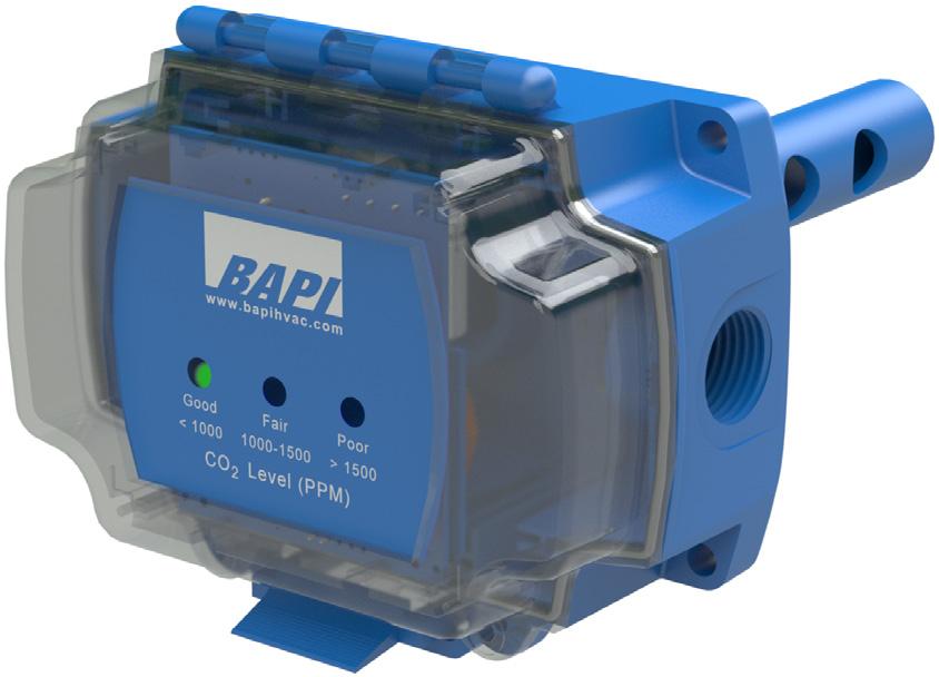
2 CO 2 Kit Product Identification and Overview BAPI s CO 2 Sensor Kit is designed to calibrate and verify the operation of all BAPI s room and duct CO 2 sensors. Items included in the Kit are: A CD containing test software and cable drivers A communications cable to connect a computer to the BAPI CO 2 sensor A funnel used as a gas shroud Tubing to connect the funnel to the test gases Rubber bands to secure the funnel to the BAPI CO 2 sensor Shunt jumpers to place the BAPI CO 2 sensor into the test mode Options An optional carrying case that fits the BAPI test kit along with a customer supplied regulator and two gas canisters is available. Please request (BA/CO2-C) when ordering. Equipment supplied by the customer: Test gases (Two 17 or 34 liter gas canisters (3 x 10 ¾ ), CO 2 concentrations described below) 0.5 liter per minute test gas flow regulator Laptop computer running Windows 97 or later Fig 1: Kit Two CO 2 calibration gas concentrations are required to perform a complete calibration as explained in the calibration section of this document: the single point gas at a concentration of 400 to 800 ppm, and the span gas at a concentration of 1,000 to 1,200 ppm. Test gases and flow regulators can be purchased online or through local HVAC distributors. A few online sources for the test gases are: Table of Contents Section 1. Loading the Test Software onto your Computer (Windows only, WIN97 or later) Section 2. Running the Software and Communicating with the CO 2 Sensor Section 3. Connecting the Test Gases to the CO 2 Sensor Section 4. Sensor Performance Tests - Single Point Check and Span Check Section 5. Sensor - Single Point and Span Section 6. Ending the Test Session Best practice is to read all the steps in a section before performing them. If you are running Windows 7 or greater, check your screen resolution for compatibility with BAPI s CO 2 sensor software. To do this, right click on the Desktop -> then left click on Personalize -> then left click on the word Display. Verify that the Smaller - 100% radio button is selected. If it is selected, close that window. If it is not selected, click on it and restart the computer. Section 1 - Loading the Test Software Step 1.1 Place the BAPI test software CD into your computer s CD drive. The install program will automatically start. On some Windows 7 computers, you may see the AutoPlay popup (Fig 2). If you see this window, click on Run setup.exe. Step 1.2 When the install program starts, you will see the Setup Wizard pop-up. Click on Next. Step 1.3 This brings up the Installation Folder pop-up. If you wish to install the program to another directory, enter the path in the folder line, then click on Next. Continued on next page... Fig 2: AutoPlay Pop-Up 2 of 8


 Double click on the BAPI CO 2 icon (Fig 3) to start the program. Fig 3: Software Icon Step 2.2 The Software startup screen will appear.")
3 CO 2 Kit Section 1 - Loading Software continued... Step 1.4 Confirm installation by clicking on Next on the Confirm Installation pop-up. If your computer displays a pop-up window warning you about the program modifying your computer, click Yes to allow the modification. Step 1.5 A status bar on the Installing pop-up will display the installation progress. Depending on your computer, this may take up to five minutes. If your computer displays a pop-up window warning you about the program modifying your computer, click Yes to allow the modification. Step 1.6 When installation is complete, click Close on the Installation pop-up to exit the installation program. Remove the CD from the CD drive. Section 2 - Running the Software and Communicating with the CO 2 Sensor Step 2.1 Plug the Communications into a USB port on the test computer. (Use the same port for all subsequent tests.) Double click on the BAPI CO 2 icon (Fig 3) to start the program. Fig 3: Software Icon Step 2.2 The Software startup screen will appear. Configure the serial port by clicking on Tools, Serial Port and Configure (Fig 4). A Serial Port Properties dialog box will open (Fig 5). In this example, the Communications is configured as COM4 but your computer may use a different serial port. After selecting the port, click OK. Then open the serial port by clicking on Tools, Serial Port and Open (Fig 6). Continued on next page... Fig 4: Configuring the Serial Port with the Software. Fig 5: Serial Port Properties Dialogue Box. Fig 6: Opening the Serial Port. 3 of 8

 onto the terminals to place the unit in CAL or PRG mode as shown in Figures 7-11 below. Black Wire J19 Jumper J2 Jumper Fig.")
4 CO 2 Kit Section 2 - Running the Software and Communicating with the CO 2 Sensor continued... Step 2.3 Remove the CO 2 wall sensor from its backplate or open the cover of the BAPI-Box duct unit to expose the circuit board. Plug the Communications onto the circuit board connector as shown in the ovals in Figures 7-11 below. Place a shunt jumper (included with the kit) onto the terminals to place the unit in CAL or PRG mode as shown in Figures 7-11 below. Black Wire J19 Jumper J2 Jumper Fig. 7: Duct CO 2 Unit J19 Jumper Black Wire Fig. 8: BAPI-Stat 3 Unit Black Wire Fig. 9: BAPI-Stat Quantum Prime Unit J2 Jumper Black Wire Fig. 10: BAPI-Stat 4 Unit Black Wire J1 Jumper Fig. 11: BAPI-Stat Quantum Unit Step 2.4 Click on the magnifying glass to search for the CO 2 sensor (Fig 12). When the software successfully identifies the sensor, information for that specific CO 2 sensor is automatically filled in (Fig 13). Each sensor has unique information, so your sensor will have different information from that shown in Fig 13. If your computer does not display the CO 2 sensor information, go to Step 2.5. If the CO 2 sensor information is displayed, go to Step 2.6. Fig 12: Detect Sensor Fig 13: Displaying Sensor Information 4 of 8
 If the computer cannot cannot communicate with the CO 2 sensor, you will get an error message saying No device found (Fig 14).")

5 CO 2 Kit Section 2 - Running the Software and Communicating with the CO 2 Sensor continued... Step 2.5 (Skip if sensor information is displayed in Step 2.4) If the computer cannot cannot communicate with the CO 2 sensor, you will get an error message saying No device found (Fig 14). Try each of the solutions listed below, then click on the Rescan button. If the Rescan button is grayed out, you will have to close and reopen the software. Possible Solutions Make sure that the jumper is properly positioned on the sensor under test. Make sure that the test cable is securely plugged into the computer and that the cable is properly connected to the sensor under test. Try another USB port on your computer. Try a different serial port from the Tools/ Serial Port/Configure menu. Fig 14: Communications Error Message Step 2.6 (Sensor information must be displayed in Step 2.4) Click on the Charts tab and the Start button to begin trending the CO 2 sensor s reading over time (Fig 15). Be careful not to breathe on the sensor under test as this could affect the readings. A small window in the upper left part of the screen (green circle on Fig 15) shows the current CO 2 ppm reading. During the rest of this test, this is the only place where the current CO 2 reading is shown. The display on the front of the CO 2 sensor is locked during this test and will not display the CO 2 concentration correctly. To export the trend data, use the File menu to create and export a CSV text file which is easily read by spreadsheet programs. Fig 15: CO 2 Sensor Trend 5 of 8


. Step 3.")
.")
.")


6 CO 2 Kit Section 3 - Connecting the Test Gases Step 3.1 Make sure that the rubber bands are tied together. For these pictures, rubber bands of different colors were used for clarity. Step 3.2 Remove the tubing from the funnel. Place the funnel over the gold colored CO 2 sensor. Hook one of the rubber bands over the funnel s spout (Fig 17). Step 3.3 Pull the rubber bands around the enclosure (Fig 18). Step 3.4 Loop the rubber band over the funnel s spout (Fig 19). Fig 16: Tubing, funnel and rubber bands. Step 3.5 Thread the tubing into the funnel s spout about 1 inch (2.5 cm). Figures 20 and 21 show the proper positioning of the funnel and test cable on the BAPI-Stat 3 and BAPI-Stat 4 room sensors. Figure 22 shows proper positioning for the BAPI-Box duct sensor. Step 3.6 Screw the regulator onto the canister of test gas until it is snug. Attach the tubing to the output port of the regulator. Figure 23 shows a complete setup. Fig 17: Place the funnel spout over the gold-colored CO 2 sensor and hook the rubber band over the spout. Fig 18: Pull the rubber band around the enclosure. Fig 19: Hook the rubber band over the spout. Fig 20: BAPI-Stat 3 room sensor. Fig 21: BAPI-Stat 4 room sensor. Fig 22: BAPI-Box duct sensor. Fig 23: Test setup complete. 6 of 8
7 CO 2 Kit Section 4 - Sensor Performance Tests Sensor performance tests should only be conducted after the CO 2 sensor has been installed and continuously powered for a minimum of 21 days. There are two different performance tests described below: Single Point Check and Span Check. The Single Point Check tests the sensor s offset or accuracy at a single concentration, while the Span Check tests the sensor s slope or accuracy at two different concentrations. It is the responsibility of the test engineer, test technician or commissioning agent to determine which tests are required. Before starting the test, make sure the calibration program is running as described in Section 2 and that the funnel is connected to the sensor as described in Section 3. SINGLE POINT CHECK Step 4.1 Connect a CO 2 test gas cylinder with a concentration of 400 to 800 ppm to the regulator. Open the regulator valve fully. The regulator will limit the flow to 0.5 liters per minute. If the cylinder was in a very hot or cold environment, it is recommended to allow 1 hour for the cylinder to reach room temperature. Step 4.2 Place the software into the charting mode as described in Step 2.6 to view the CO 2 measurement. Be careful not to breathe on the sensor under test. It may take several minutes for the CO 2 reading to stabilize on the chart. Step 4.3 When the reading has been stable for a minimum of 30 seconds, compare the sensor s CO 2 measurement to the concentration of test gas cylinder. If the measurement and the test gas concentration differ by more than ±30 ppm or 3% for single channel units (-ACD05 or -ACD10 in the part number) or by ±75 ppm for dual channel units (-DCD05 or DCD10 in the part number), BAPI recommends that you perform a Single Point as described in Section 5. If a Span Check is required, complete the Span Check described below before performing the Single Point. Step 4.4 If the Single Point Check is the only testing that is required and no calibration is necessary, go to Section 6 which describes the steps for ending the testing session. SPAN CHECK Step 4.5 Connect a CO 2 test gas cylinder with a concentration of 1,000 to 1,200 ppm to the regulator. Open the regulator valve fully. The regulator will limit the flow to 0.5 liters per minute. If the cylinder was in a very hot or cold environment, it is recommended to allow 1 hour for the cylinder to reach room temperature. Step 4.6 Place the software into the charting mode as described in Step 2.6 to view the CO 2 measurement. Be careful not to breathe on the sensor under test. It may take several minutes for the CO 2 reading to stabilize on the chart. Step 4.7 When the reading has been stable for a minimum of 30 seconds, compare the sensor s CO 2 measurement to the CO 2 concentration of test gas cylinder. If the measurement and the test gas concentration differ by more than ±30 ppm or 3% for single channel units (-ACD05 or -ACD10 in the part number) or by ±75 ppm for dual channel units (-DCD05 or DCD10 in the part number), BAPI recommends that you perform a Span as described in Section 5. Step 4.8 If a calibration is not required, go to Section 6 which describes the steps for ending the testing session. Section 5 - Sensor Sensor calibration should only be conducted after the CO 2 sensor has been installed and continuously powered for a minimum of 21 days. BAPI recommends conducting the performance tests of section 4 to determine if calibration is necessary. There are two calibrations that may be performed: Single Point and Span. The Single Point sets the sensor s offset at a single concentration, while the Span sets the sensor s slope or calibration at two different concentrations. It is the responsibility of the test engineer, test technician or commissioning agent to determine which calibrations are required. Before starting the test, make sure the calibration program is running as described in Section 2 and that the funnel is connected to the sensor as described in Section 3. Continued on next page... 7 of 8
.")
8 CO 2 Kit Section 5 - Sensor continued... SINGLE POINT CALIBRATION Step 5.1 Connect a CO 2 test gas cylinder with a concentration of 400 to 800 ppm to the regulator. Open the regulator valve fully. The regulator will limit the flow to 0.5 liters per minute. Step 5.2 Place the software in Charting mode as described in Step 2.6 to view the CO 2 measurement (Fig 15). Be careful not to breathe on the sensor under test. It may take 1 to 10 minutes for the CO 2 reading to stabilize. Step 5.3 When the reading has stabilized for at least 30 seconds, click on the Stop button in the lower left corner (Fig 15) and then the Settings Tab. This brings up the Sensor Screen (Fig 24). Step 5.4 Enter the CO 2 concentration from the cylinder into the ppm window under Single Point (Fig 24). Press the Start button. A pop-up window will open showing the calibration progress (Fig 25). When the pop-up closes, the Single Point is complete. Step 5.5 If a Span is not required, go to Section 6 which describes the steps for ending the testing session. Fig 24: Sensor Screen SPAN CALIBRATION Step 5.6 Connect a CO 2 test gas cylinder with a concentration of 1,000 to 1,200 ppm to the regulator. Open the regulator valve fully. The regulator will limit the flow to 0.5 liters per minute. Step 5.7 Place the software into the Charting mode as described in Step 2.6 to view the CO 2 measurement (Fig 15). Be careful not to breathe on the sensor under test. It may take 1 to 10 minutes for the CO 2 reading to stabilize. Step 5.8 When the reading has stabilized for at least 30 seconds, Fig 25: Calibrating Pop-up Window click on the Stop button in the lower left corner (Fig 15) and then the Settings Tab. This brings up the Sensor Screen (Fig 24). Step 5.9 Enter the CO 2 concentration from the cylinder into the ppm window under Span. Press the Start button. A pop-up window will open showing the calibration progress (Fig 25). When the pop-up closes, the Span is complete. Step 5.10 If no further testing or calibration is required, go to Section 6 which describes the steps for ending the testing session. Section 6 - Ending the Test Session Perform these steps in when you are ready to end the testing session. Step 6.1 Step 6.2 Step 6.3 Step 6.4 Shut down the program. Close the regulator valve on the test gas. Remove the funnel, communications cable and jumper from the sensor. Close the cover for duct units or reattach the wall sensor to its base plate. 8 of 8
The ideal K-12 science microscope solution. User Guide. for use with the Nova5000
 The ideal K-12 science microscope solution User Guide for use with the Nova5000 NovaScope User Guide Information in this document is subject to change without notice. 2009 Fourier Systems Ltd. All rights
USER MANUAL. ScanFlex AUTOMATED SCANNING DEVICE SCANFLEX Rev 5.0
 USER MANUAL ScanFlex AUTOMATED SCANNING DEVICE 05-12-17 SCANFLEX 3.1.4 Rev 5.0 Culturing Cells in a Mechanically Active Environment Flexcell International Corporation 2730 Tucker Street, Suite 200 Burlington,
Veterinary Digital X-Ray System Quick Start Guide
 1 Veterinary Digital X-Ray System Quick Start Guide 2 SOPIX² X-Ray Sensors Quick Start Guide ***PERFORM THIS STEP BEFORE PLUGGING IN THE SENSOR*** Step 1 Load the CD: If you have already plugged in the
Exercise 8. Troubleshooting a Radar Target Tracker EXERCISE OBJECTIVE
 Exercise 8 Troubleshooting a Radar Target Tracker EXERCISE OBJECTIVE When you have completed this exercise, you will be able to apply an efficient troubleshooting procedure in order to locate instructor-inserted
BAPI-Stat 4 X-Combo, Room %RH and Temp. Sensor BA/BS4XC Installation & Operating Instructions
 Overview and Identification The BAPI-Stat 4 X-Combo () Room Unit features 4 output channels and optional local indication of temperature and humidity. Additional options include Temperature Setpoint, Humidity
MAXI Remote Location Kit MRLK 900 Installation and Configuration Manual
 MAXI Remote Location Kit MRLK 900 Installation and Configuration Manual 01/18 635079 Table of Contents Introduction... 3 Materials Included... 3 Setup Overview... 4 Radio Configuration Overview:... 4 FreeWaveTool
Issue No: MG025 Date: 05 June McMurdo SmartFind R5 GMDSS Radio IMO MSC. 1/Circ Update procedure
 Installation SERVICE BULLETIN Issue No: MG025 Date: 05 June 2017 McMurdo SmartFind R5 GMDSS Radio IMO MSC. 1/Circ. 1460 Update procedure Product Affected: McMurdo R5 GMDSS VHF Handheld Radio Reason: Compliance
2012 Monitored Rehab Systems E1201 Manual Kneelax. Installation and user manual
 2012 Monitored Rehab Systems E1201 Manual Kneelax Installation and user manual Table of contents CHAPTER 1 Installation Manual... 3 1.1 Install Kneelax USB driver... 3 1.2 Detect COM-port... 6 1.3 Software
ACCU-GOLD QUICK START MANUAL
 ACCU-GOLD Now includes support for the light sensor (AGLS) and Accu Gold+ digitizers and sensors (AGDM+, AGMS DM+) Nomenclature AGDM Accu-Gold Digitizer Module RGDM Rapid-Gold Digitizer Module RGDM-MA
GE Sensing. Introduction. Wiring Diagrams (Typical) Field Calibration. Installing the Sensor
 Field Calibration. Installing the Sensor") clear mode enter clear mode enter GE Sensing Introduction The GE Telaire Vaporstat 900 sensor measures in applications in the range of 0 to 0 F dew point. The sensor package is designed for wall mounting.
clear mode enter clear mode enter GE Sensing Introduction The GE Telaire Vaporstat 900 sensor measures in applications in the range of 0 to 0 F dew point. The sensor package is designed for wall mounting.
ifeel Sensor USER GUIDE SUPPLEMENT
 ifeel Sensor USER GUIDE SUPPLEMENT Choose Your ifeel Sensor There are two versions of the ifeel Sensor: USB and Bluetooth. Read the section of the user guide that matches your sensor. IFEEL BLUETOOTH SENSOR
MicroLab 500-series Getting Started
 MicroLab 500-series Getting Started 2 Contents CHAPTER 1: Getting Started Connecting the Hardware....6 Installing the USB driver......6 Installing the Software.....8 Starting a new Experiment...8 CHAPTER
Vinyl Cutter Instruction Manual
 Vinyl Cutter Instruction Manual 1 Product Inventory Inventory Here is a list of items you will receive with your vinyl cutter: Product components (Fig.1-4): 1x Cutter head unit complete with motor, plastic
Radio Link Starter Kit
 Radio Link Starter Kit Installation Manual BARTLETT Instrument Co. 1032 Avenue H Fort Madison, IA 52627 319-372-8366 www.bartinst.com Table of Contents Radio Link Starter Kit Manual... 3 System Requirements...
Happy Link Software INSTRUCTION MANUAL
 Happy Link Software INSTRUCTION MANUAL 101001E-3 HAPPY Contents Regarding this software Normal Operation -------------------------------------------------------------------------------------------------
Solinst Remote Radio Link (RRL Gold) User Guide
 User Guide") Solinst Remote Radio Link (RRL Gold) User Guide Version 1.4.0 March 21, 2016 2016 Solinst Canada Ltd. All rights reserved. Printed in Canada. Solinst and Levelogger are registered trademarks of Solinst
Solinst Remote Radio Link (RRL Gold) User Guide Version 1.4.0 March 21, 2016 2016 Solinst Canada Ltd. All rights reserved. Printed in Canada. Solinst and Levelogger are registered trademarks of Solinst
Sutron SatLink2 Troubleshooting Instructions
 Sutron SatLink2 Troubleshooting Instructions A. SatLink2 (SL2) symptoms: Missing or partial data on LRGS (check DIS-MSG for frequency and EIRP; use HDR DCP Message header list. B. Equipment and tools needed:
23070 / Digital Camera Owner s Manual
 23070 / 23072 Digital Camera Owner s Manual 2007 Sakar International, Inc. All rights reserved. 2007 Crayola Windows and the Windows logo are registered trademarks of Microsoft Corporation. All other trademarks
Instruction Manual ABM HART Gateway Software. Instruction Manual Revision A.1
 Instruction Manual ABM HART Gateway Software Instruction Manual Revision A.1 Table of Contents Section 1: Getting Started... 3 1.1 Setup Procedure... 3 1.2 Quick Setup Guide for Ultrasonic Sensors... 11
Finding Offsets for Multiple Spindles/Air Drills
 888-680-4466 ShopBotTools.com Finding Offsets for Multiple Spindles/Air Drills Copyright 2016 ShopBot Tools, Inc. page 1 Copyright 2016 ShopBot Tools, Inc. page 2 Introduction This document explains how
MityCAM-B2521 EPIX XCAP User s Guide
 MityCAM-B2521 EPIX XCAP User s Guide (CT031 Revision 1) Page 1 of 13 60-000014 Contents 1 Installing Laptop Express Card... 3 2 Using the Camera in Single Camera Link mode (Laptop)... 3 3 Single Camera
Magic Wand Portable Scanner with Auto-Feed Dock. PDSDK-ST470-VP-BX2 User Manual
 Magic Wand Portable Scanner with Auto-Feed Dock PDSDK-ST470-VP-BX2 User Manual Table of Contents 1. KEY FEATURES... 2 2. FUNCTIONAL PARTS... 2 3. EXPLANATION OF THE STATUS ICONS... 4 4. GETTING STARTED...
Combo Scanner. User Manual
 Combo Scanner User Manual I. Unpack the Combo Scanner Backlight Holder Combo Scanner Business card Fixture Photo/Business Card Holder User Manual Quick Installation Guide Note This Combo Scanner supports
Assembly Guide for Printrbot - Simple Maker s Edition 1405
 Assembly Guide for Printrbot - Simple Maker s Edition 1405 Last update: March 2016 Please Note: be careful on the steps that are underlined 1 Contents Tools Needed:... 3 First step: Check components and
DPM Kit DK-1. Using the DPM Kit
 DPM Kit DK-1 Using the DPM Kit To ensure safe usage with a full understanding of this product's performance, please be sure to read through this manual completely. Store this manual in a safe place where
Advanced Test Equipment Rentals
 Established 1981 Advanced Test Equipment Rentals Solmetric PVA-600 PV Analyzer Quick Start Guide www.atecorp.com 800-404-ATEC (2832) : When using the wireless PVA Sensor Kit or manual sensors, the end
ivu Plus Quick Start Guide P/N rev. A -- 10/8/2010
 P/N 154721 rev. A -- 10/8/2010 Contents Contents 1 Introduction...3 2 ivu Plus Major Features...4 2.1 Demo Mode...4 2.2 Sensor Types...4 2.2.1 Selecting a Sensor Type...5 2.3 Multiple Inspections...6 2.3.1
Mediasite Desktop Recorder: Recording a Lecture 2017
 Mediasite Desktop Recorder: Recording a Lecture 2017 This lesson will show you how to record a presentation using the Mediasite Desktop Recorder. In browser go to - https://http://mediasite.umaryland.edu/mediasite/mymediasite
Radio Link Starter Kit
 Radio Link Starter Kit Installation Manual BARTLETT Instrument Co. 1032 Avenue H Fort Madison, IA 52627 319-372-8366 www.bartinst.com Table of Contents Radio Link Starter Kit Manual... 3 System Requirements...
Quick Start Guide. Setup and Scanning. Try the Additional Features. English
 English Quick Start Guide Be sure to install the software programs before connecting the scanner to the computer! Setup and Scanning Check the Package Contents p.3 Install the Software Windows Macintosh
Congratulations on your decision to purchase the Triquetra Auto Zero Touch Plate for All Three Axis.
 Congratulations on your decision to purchase the Triquetra Auto Zero Touch Plate for All Three Axis. This user guide along with the videos included on the CD should have you on your way to perfect zero
Blue Bamboo P25 Device Manager Guide
 Blue Bamboo P25 Device Manager Guide Version of Device Manager: 1.1.28 Document version: 2.3 Document date: 2011-09-20 Products: P25 / P25-M / P25i / P25i-M BLUE BAMBOO Headquarters Blue Bamboo Transaction
Universal Camera Registration User Guide for ILS 9.75 & 12.75
 User Guide for ILS 9.75 & 12.75 www.ulsinc.com Overview Camera Registration allows the laser system to automate the alignment of a vector path with the material for the purpose of tightening process control
Laboratory 1: Motion in One Dimension
 Phys 131L Spring 2018 Laboratory 1: Motion in One Dimension Classical physics describes the motion of objects with the fundamental goal of tracking the position of an object as time passes. The simplest
TM5. Guide Book. Hardware Version: 2.00 Software Version: 1.62
 TM5 Guide Book Hardware Version: 2.00 Software Version: 1.62 ii Release Date : 2017-07-10 The information contained herein is the property of Techman Robot Corporation (hereinafter referred to as the Corporation).
About the DSR Dropout, Surge, Ripple Simulator and AC/DC Voltage Source
 About the DSR 100-15 Dropout, Surge, Ripple Simulator and AC/DC Voltage Source Congratulations on your purchase of a DSR 100-15 AE Techron dropout, surge, ripple simulator and AC/DC voltage source. The
CHAPTER1: QUICK START...3 CAMERA INSTALLATION... 3 SOFTWARE AND DRIVER INSTALLATION... 3 START TCAPTURE...4 TCAPTURE PARAMETER SETTINGS... 5 CHAPTER2:
 Image acquisition, managing and processing software TCapture Instruction Manual Key to the Instruction Manual TC is shortened name used for TCapture. Help Refer to [Help] >> [About TCapture] menu for software
MBC DG GUI MBC INTERFACE
 MBC DG GUI MBC INTERFACE User Manual Version 2.6 Table des matières Interface - Introduction... 3 Interface - Setup... 3 Minimum Computer Requirements... 3 Software installation... 3 Hardware Setup...
Exercise 6. Range and Angle Tracking Performance (Radar-Dependent Errors) EXERCISE OBJECTIVE
 EXERCISE OBJECTIVE") Exercise 6 Range and Angle Tracking Performance EXERCISE OBJECTIVE When you have completed this exercise, you will be familiar with the radardependent sources of error which limit range and angle tracking
Exercise 6 Range and Angle Tracking Performance EXERCISE OBJECTIVE When you have completed this exercise, you will be familiar with the radardependent sources of error which limit range and angle tracking
Table of Contents. Chapter 1: Software Installation...1. Chapter 2: Running the Software II. Daily Practical Operation...10
 Product Manual Table of Contents Chapter 1: Software Installation.................................1 Chapter 2: Running the Software............................... 2 I. The Initial Defining in Lock Management
Altair Avionics Corporation Monitor Link Program
 Altair Avionics Corporation Monitor Link Program Altair Avionics Monitor Link Program MLP User s Guide By Tyler Dawbin Approved By: Doug Thompson, General Manager David L. Fetherston, Manager Engineering
Quick Start Guide. Contents
 1 Quick Start Guide Contents Powering on the Machine Login/Password Entry Jaw Set Up High Security Cut by Code High Security Jaw Set Up Edge Cut Cut by Code Edge Cut Cut by Decode Cutter Replacement Tracer
Welcome 1. Precaution
 Table of Contents EN Precaution....2 Preparation.. 4 Standard accessories....4 Parts Names & Functions...5 Computer System requirements.... 6 Technical Specifications 7 Install the software.. 7 Start Microscope.8
Instruction Manual. Ultrasonic and Radar
 Instruction Manual ABM Gateway Software for 3 & 4 wire Ultrasonic and Radar Instruction Manual Revision 5.8 NOTE: Windows 7 and 8 users are asked to use default screen size (100%). To change from Larger
KoPa Scanner. User's Manual A99. Ver 1.0. SHENZHEN OSTEC OPTO-ELECTRONIC TECHNOLOGY CO.,LTD.
 KoPa Scanner A99 User's Manual Ver 1.0 SHENZHEN OSTEC OPTO-ELECTRONIC TECHNOLOGY CO.,LTD. http://www.ostec.com.cn Content Chapter 1 Start... 1 1.1 Safety Warnings and Precautions... 1 1.2 Installation
CHROMACAL User Guide (v 1.1) User Guide
 User Guide") CHROMACAL User Guide (v 1.1) User Guide User Guide Notice Hello and welcome to the User Guide for the Datacolor CHROMACAL Color Calibration System for Optical Microscopy, a cross-platform solution that
CHROMACAL User Guide (v 1.1) User Guide User Guide Notice Hello and welcome to the User Guide for the Datacolor CHROMACAL Color Calibration System for Optical Microscopy, a cross-platform solution that
TEK-TROL HART GATEWAY SOFTWARE. Operating Instruction Manual.
 TEK-TROL HART GATEWAY SOFTWARE Operating Instruction Manual www.tek-trol.com Table of Contents 1 Getting Started... 2 1.1 Setup Procedure... 2 1.2 Quick Setup Guide for Radar Sensors... 10 2 Level device
Start Here. Installing your Microtek ScanMaker 9800XL Plus PC:
 Start Here Installing your Microtek ScanMaker 98XL Plus Step : Unpack Contents. Optional package items depend on the scanner configuration that you purchased. Unpack your scanner package and check for
Quick Start Guide for the PULSE PROFILING APPLICATION
 Quick Start Guide for the PULSE PROFILING APPLICATION MODEL LB480A Revision: Preliminary 02/05/09 1 1. Introduction This document provides information to install and quickly start using your PowerSensor+.
PhenoMaster / LabMaster Phenotyping Research Platform
 Operating Instructions PhenoMaster / LabMaster Phenotyping Research Platform SOFTWARE Operating Instructions Calibration Description of Standard Components 2 PhenoMaster/LabMaster Software Operating Instructions
reference guide reference guide reference guide
 hp photosmart 240 series reference guide reference guide reference guide contents 1 welcome..................................... 1 find more information.............................. 1 what s in the box.................................
Optika ISview. Image acquisition and processing software. Instruction Manual
 Optika ISview Image acquisition and processing software Instruction Manual Key to the Instruction Manual IS is shortened name used for OptikaISview Square brackets are used to indicate items such as menu
Faculty of Electrical & Electronics Engineering BEE4233 Antenna and Propagation. LAB 1: Introduction to Antenna Measurement
 Faculty of Electrical & Electronics Engineering BEE4233 Antenna and Propagation LAB 1: Introduction to Antenna Measurement Mapping CO, PO, Domain, KI : CO2,PO3,P5,CTPS5 CO1: Characterize the fundamentals
For more information:
 Verify Tab Click on the Verify tab to compare the measured and predicted max power values. Their ratio, in percent, is the Performance Factor. Solmetric PVA-600 PV Analyzer Quick Start Guide History Tab
Downloading a ROBOTC Sample Program
 Downloading a ROBOTC Sample Program This document is a guide for downloading and running programs on the VEX Cortex using ROBOTC for Cortex 2.3 BETA. It is broken into four sections: Prerequisites, Downloading
NOVA. Getting started
 NOVA Getting started Table of contents Introduction... 7 The philosophy of Nova... 8 1 Nova installation... 11 1.1 Requirements... 11 1.2 Software installation... 11 1.2.1.NET 4.0 framework installation...
Table 1. Placing the Sensor in the Sensor Cradle. Step Instruction Illustration
 Table 1. Placing the Sensor in the Sensor Cradle Step Instruction Illustration 1. A. Check "U-shaped" Positioner. The number pointing towards the Sensor (1 or 2) must correspond with the Sensor's size.
IVCAD VNA Base Load Pull with Active/Hybrid Tuning. Getting Started v3.5
 IVCAD VNA Base Load Pull with Active/Hybrid Tuning Getting Started v3.5 1 Setting and Configuration Block Diagram... 3 1.1 VNA setup... 5 1.2 RF source setup... 6 1.3 Power meter setup... 7 1.4 Source
I. Unpack FilmScan35 I
 Version 3.01 Jun-2009 I. Unpack FilmScan35 I Note This film scanner supports Windows XP and Vista (32/64bits) via USB 2.0 only. We strongly suggest using a clean, dry, non-alcohol cotton swab to insert
Installation Guide. Suitable for: OEM Integration OEM Installation Retro Fit Installation
 Installation Guide Suitable for: OEM Integration OEM Installation Retro Fit Installation DTI AngleBlaster release 1.1 DTI 2010 Overview Angleblaster Installation Guide A-1 To obtain the best accuracy from
What is a WQSensor? Software Installation. Uninstalling WQSensors Software. NexSens Technology, Inc. TABLE OF CONTENTS
 Revision 2.01 TABLE OF CONTENTS 1 Sensor Operation... 3 1.1 ph & Temperature Sensors... 3 1.1.1 WQ-pH ph & Temperature Sensor...3 1.1.2 Making ph Sensor Measurements...4 1.1.3 Maintenance and Care...7
Contents. Overview Introduction...3 Capabilities...3 Operating Instructions Installation...4 Settings... 5
 User s Manual Contents Overview................................................................. 3 Introduction..............................................................3 Capabilities...............................................................3
i800 Series Scanners Image Processing Guide User s Guide A-61510
 i800 Series Scanners Image Processing Guide User s Guide A-61510 ISIS is a registered trademark of Pixel Translations, a division of Input Software, Inc. Windows and Windows NT are either registered trademarks
Field Device Manager Express
 Honeywell Process Solutions Field Device Manager Express Software Installation User's Guide EP-FDM-02430X R430 June 2012 Release 430 Honeywell Notices and Trademarks Copyright 2010 by Honeywell International
RigExpert TI-7 USB Transceiver Interface User s manual
 RigExpert TI-7 USB Transceiver Interface User s manual Please read this manual before attempting to use the RigExpert TI-7 device. - - 2 - Table of contents 1. What is a RigExpert TI-7?... 4 2. Specifications...
SCOUT Mobile User Guide 3.0
 SCOUT Mobile User Guide 3.0 Android Guide 3864 - SCOUT February 2017 SCOUT Mobile Table of Contents Supported Devices...1 Multiple Manufacturers...1 The Three Tabs of SCOUT TM Mobile 3.0...1 SCOUT...1
XI. Rotary Attachment Setups
 XI. Rotary Attachment Setups 1) Turn off the laser. 2) Put the rotary attachment onto the engraving table. Ensure the two screw holes on right side of rotary attachment match the two corresponding holes
MIDLAND PROGRAMING G14
 MIDLAND PROGRAMING G14 1. PROGRAMMING CAPABILITY Welcome to the MIDLAND Programming software! It s a programming software specifically designed for G14 and must be used in conjunction with the dedicated
Apple Photos Quick Start Guide
 Apple Photos Quick Start Guide Photos is Apple s replacement for iphoto. It is a photograph organizational tool that allows users to view and make basic changes to photos, create slideshows, albums, photo
DXXX Series Servo Programming...9 Introduction...9 Connections HSB-9XXX Series Servo Programming...19 Introduction...19 Connections...
 DPC-11 Operation Manual Table of Contents Section 1 Introduction...2 Section 2 Installation...4 Software Installation...4 Driver Installastion...7 Section 3 Operation...9 D Series Servo Programming...9
WELCOME TO BINGO CALLER
 WELCOME TO BINGO CALLER Dee Dee Software Design & Sales A Division Of Seocom Enterprises Unlimited LLC Bingo Caller was designed to be used at a computer screen resolution of at least 1024 x 768, along
USB Microphone. Marshall Electronics
 USB Microphone Marshall Electronics Warranty Marshall microphones are guaranteed against defects in material and workmanship for one year from date of purchase. Should you encounter any problem with this
RK PPM Hexane Transmitter Operator s Manual
 65-2461RK PPM Hexane Transmitter Operator s Manual Part Number: 71-0144RK Revision: 0 Released: 2/16/11 RKI Instruments, Inc. www.rkiinstruments.com WARNING Read and understand this instruction manual
User s Guide HD iflex Scanner
 User s Guide HD iflex Scanner Contents Table of Contents About This Guide 2 Overview of Scanner 3 Scanner Front View 3 Scanner Rear View 4 Installation 5 System requirements 5 Installation Steps 5 Turning
ArbStudio Triggers. Using Both Input & Output Trigger With ArbStudio APPLICATION BRIEF LAB912
 ArbStudio Triggers Using Both Input & Output Trigger With ArbStudio APPLICATION BRIEF LAB912 January 26, 2012 Summary ArbStudio has provision for outputting triggers synchronous with the output waveforms
Sodium Thiosulphate and hydrochloric acid
 Sodium Thiosulphate and hydrochloric acid Introduction The rate of reaction can be altered by varying temperature or concentration, or by changing the surface area of a solid reactant, or by adding a catalyst.
Exercise 2-2. Four-Wire Transmitter (Optional) EXERCISE OBJECTIVE DISCUSSION OUTLINE. Ultrasonic level transmitter DISCUSSION
 EXERCISE OBJECTIVE DISCUSSION OUTLINE. Ultrasonic level transmitter DISCUSSION") Exercise 2-2 Four-Wire Transmitter (Optional) EXERCISE OBJECTIVE Become familiar with HART point-to-point connection of a four-wire transmitter. DISCUSSION OUTLINE The Discussion of this exercise covers
Exercise 2-2 Four-Wire Transmitter (Optional) EXERCISE OBJECTIVE Become familiar with HART point-to-point connection of a four-wire transmitter. DISCUSSION OUTLINE The Discussion of this exercise covers
USB Line Camera 8M. Coptonix GmbH
 USB Line Camera 8M Coptonix GmbH Luxemburger Str. 31 D 13353 Berlin Phone: +49 (0)30 61 74 12 48 Fax: +49 (0)30 61 74 12 47 www.coptonix.com support@coptonix.com 2 The USB Line Camera 8M is an easy to
USB.007 Studio Quality USB Stereo Condenser Mic. User Manual
 USB.007 Studio Quality USB Stereo Condenser Mic User Manual Congratulations on your purchase of the MXL USB.007 which uses two gold diaphragm capsules in an X/Y pattern for stereo recording. MXL microphones
MANUAL. Textron Motors Diagnostic Tool. This manual is valid for the following Textron Motors Diagnostic Tool:
 MANUAL Textron Motors Diagnostic Tool This manual is valid for the following Textron Motors Diagnostic Tool: 0507 TD0507_HB Rev F 6..05 en_english Read the manual before performing the task on the engine.
NIS-Elements: Grid to ND Set Up Interface
 NIS-Elements: Grid to ND Set Up Interface This document specifies the set up details of the Grid to ND macro, which is included in material # 97157 High Content Acq. Tools. This documentation assumes some
OPERATION MANUAL MIMAKI ENGINEERING CO., LTD.
 OPERATION MANUAL MIMAKI ENGINEERING CO., LTD. http://www.mimaki.co.jp/ E-mail:traiding@mimaki.co.jp D200674 About FineCut for CorelDRAW Thank you very much for purchasing a product of Mimaki. FineCut,
ExpoM - ELF User Manual
 ExpoM - ELF User Manual Version 1.4 ExpoM - ELF User Manual Contents 1 Description... 4 2 Case and Interfaces... 4 2.1 Overview... 4 2.2 Multi-color LED... 5 3 Using ExpoM - ELF... 6 3.1 Starting a Measurement...
Studuino Color Sensor Manual
 Studuino Color Sensor Manual This manual explains the Studuino Programming Environment and how to use it. As the Studuino Programming Environment develops, this manual may be edited or revised. You can
GXCapture 8.1 Instruction Manual
 GT Vision image acquisition, managing and processing software GXCapture 8.1 Instruction Manual Contents of the Instruction Manual GXC is the shortened name used for GXCapture Square brackets are used to
Topcon Receiver Utility: GNSS Receiver Firmware Update Process. Oscar R. Cantu
 Topcon Receiver Utility: GNSS Receiver Firmware Update Process Oscar R. Cantu TRU: GNSS Receiver Firmware Update Topcon Receiver Utility (TRU), product definition Office Processing and Reporting Software
QHY367C. User s Manual Rev. 1.3
 User s Manual Rev. 1.3 This document is an online document. You may save this PDF file or print it out. QHYCCD reserves the right to change this user manual without prior notice. Package Contents please
LumaSpec 800S User Manual
 LumaSpec 800S User Manual Worldwide distribution VERSION 09112014 Prior Scientific, Ltd Cambridge, UK Prior Scientific, Inc Rockland, MA. USA Prior Scientific, GmbH Jena, Germany Prior Scientific KK Tokyo,
NOVA. Getting started
 NOVA Getting started NOVA Getting started 3 Table of contents The philosophy of Nova... 8 1 Nova installation... 11 1.1 Requirements... 11 1.2 Software installation... 11 1.2.1.NET framework installation...
The DesignaKnit USB E6000 Link 1 & 2
 The DesignaKnit USB E6000 Link 1 & 2 for the Passap / Pfaff Electronic 6000 USB E6000 Link 1 USB E6000 Link 2 What these links do The USB E6000 Link 1 enables downloading of stitch patterns from DesignaKnit
MADEinUSA OPERATOR S MANUAL. RS232 Interface Rev. A
 MADEinUSA OPERATOR S MANUAL RS232 Interface 92-3006 Rev. A www.iradion.com Iradion Laser, Inc. 51 Industrial Dr. N. Smithfield, RI 02896 (410) 762-5100 Table of Contents 1. Overview... 2 2. Equipment Required...
EMWIN User Training. For Colorado Front Range. September, 2007
 EMWIN User Training For Colorado Front Range September, 2007 Agenda 1 p.m. Getting Started SOME ASSEMBLY REQUIRED Antenna Radio equipment RealEMWIN Software installation 2:30 p.m. Basic features of RealEMWIN
User s Guide. DDS-3005 USB Operation Manual
 User s Guide DDS-3005 USB Operation Manual Table of Contents Chapter 1 Introduction...1 1.1 Introduction...1 1.2 Working Principle...1 1.3 Hardware Specification...1 Chapter 2 Installation...3 2.1 System
INSTALLATION INSTRUCTIONS
 TreadClimber INSTALLATION INSTRUCTIONS STAR TRAC FITNESS 1 of 14 635-4175 Rev: B NOTICE Installation of this product requires that 2 or more people are available to safely perform certain steps outlined
3B SCIENTIFIC PHYSICS
 B SCIENTIFIC PHYSICS Cavendish Torsion Balance 007 Operating instructions 06/8 ALF. Description The Cavendish torsion balance is for demonstrating the gravitational attraction between two masses and determining
Scanner Utility for Microsoft Windows Version 9.6. User's Guide
 P3PC-E892-03EN Scanner Utility for Microsoft Windows Version 9.6 User's Guide For Use with Microsoft Windows 98, Windows Me, Windows 2000 and Windows XP Introduction Thank you for purchasing the "Scanner
VOLTAGE. User Guide ACCESSORIES. External Sensor DT140. for MicroLog EC600 and EC V ±0.05V ±3% (before calibration)
") External Sensor VOLTAGE DT140 Range: Resolution: Accuracy: Input impedance: Calibration: OV protection: 0-10V ±0.05V ±3% (before calibration) 3MΩ 2 calibration points ±30V ACCESSORIES User Guide for MicroLog
External Sensor VOLTAGE DT140 Range: Resolution: Accuracy: Input impedance: Calibration: OV protection: 0-10V ±0.05V ±3% (before calibration) 3MΩ 2 calibration points ±30V ACCESSORIES User Guide for MicroLog
SoundCheck 11 Quick Start Guide
 Software Install Basics Upgrading From an Earlier Version If you are upgrading from an earlier version of SoundCheck 11.1 (or Beta version) you should copy the old installation folder and name it "SoundCheck
Minolta Scanner Plugin
 Minolta Scanner Plugin For a list of Minolta digitizers and Geomagic software products with which this plugin is compatible, see Release Notes for Geomagic Minolta Plugin 7.6.0.3. Copyright 2005, Raindrop
The DesignaKnit USB Brotherlink 5
 The DesignaKnit USB Brotherlink 5 for Brother electronic machines What this link does Uploading and downloading patterns to the KH930, KH940, KH950i, KH965i, and KH970 knitting machines. Interactive knitting