Please note that Robots can move without warning, wear eye protection at all times and never touch a powered robot!
|
|
|
- Marsha Mosley
- 6 years ago
- Views:
Transcription
1


2 Safety First! Updated: 18-Aug-2008 Safety First! Read and understand the documentation associated with any of the tools used in the assembly of these kits. Work in a clean, well-lit environment. Work slowly taking breaks often. Plan your work with plenty of extra time to avoid cramming to complete the project at the last minute. micromagic systems has taken every step to ensure the products sold are safe when used in a responsible manner. Therefore, micromagic systems cannot be held accountable for irresponsible, careless or reckless behavior of the builder. These kits are purely educational. Items sold by micromagic systems are not authorized for use in human contact, medical, life-saving, life-support, industrial or light industrial applications. Do not under any circumstances use these robots to move, touch, or handle dangerous or hazardous materials. Doing this could result in injury or death to the user, or damage to property. Please note that Robots can move without warning, wear eye protection at all times and never touch a powered robot! micromagic systems is not responsible for any special, incidental, or consequential damages resulting from any breach of warranty, or under any legal theory, including lost profits, downtime, goodwill, damage to or replacement of equipment or property, and any costs of recovering, reprogramming, or reproducing of data associated with the use of the mechanics, hardware or software it sells Battery Advise NiCd, NiMh, LiPo & LiIo batteries store a great amount of energy and can damage equipment or cause fire if shorted and an improper fuse is installed or bypassed. Always use an inline fuse with your battery pack. Disconnect all batteries when not in use. Store in a cool dry place. Use only the manufacturers recommended charging equipment for your batteries. Acrylic Parts

3 Hitec Servo Preparation Guide Updated: 18-Aug-2008 Before attaching servos to your robot, it is necessary to check that the servo horn is fitted correctly and in the center position. This guide will explain how this is achieved. Print this single page document with the following settings: Paper A4 or Letter, Margins 0.4", Scale 70%. tested in IE7 & Firefox Index Servo Horn Position Servo Horn Centering Servo Horn Position When you first remove your Hitec servo from the packet, the servo horn should be fitted in the position shown in Figure 1. This should be the servo center position, however, this is not guaranteed so we suggest this is checked before you begin kit assembly. (See Setting Servo Center) The holes indicated by (A) & (B) are used for attaching the horn to other mechanical assemblies. This is done with No.2 self tapping screws. Although not necessary, you may wish to open these holes up with a 1.5mm or 1/16" drill for easier assembly. Figure 1. Hitec servo splines have 24 teeth, which means the servo horn can be moved around in 15 increments. Servo Horn Centering To check if your servo horn has been fitted in the mid position (center of rotation) correctly as shown in Figure 1. you will need to power up the servo with a 1.5ms positive pulse sent every 20ms (50Hz). This can be done using an R/C style transmitter/ receiver, a p.brain-hexengine or SSC. Using p.brain-hexengine Connect a 6.0V power supply or battery pack via a switch to the SMB board, V+ to the VS screw terminal and V- to one of the GND screw terminals. Install a jumper on JP3 across pins 1-2, this sets VL = VS for single power source supply. Remove any jumpers on CN18. Connect the terminal port RJ11 4/4 connector to the serial port of your host computer using a suitable lead such as a p.brain-rj232.
4 p.brain-hexengine: 6V dc is supplied to the VS terminal via a switch, with JP3 1-2 link in place to supply VL from VS. Open up a connection in your terminal software on the host system, set the baud to match that of your HexEngine ( default = ,N,8,1). Switch on power to the SMB, you should see a RED led near the terminal block illuminate (if it does not, switch off power immediately and check your circuit). When powered up you should see the HexEngine display message in the terminal window, enter the SERVO TEST screen by typing "SERVO TEST" within your terminal screen. Once in SERVO TEST mode, select the servo you wish to test using the left/right cursor keys, press the '2' key to send the servo to the required 1.5ms mid position. The servo horn should now be in the position indicated by Figure 1. Using Lynxmotion SSC32 Please visit the following link: lynxmotion.com/images/html/build046.htm Once you have your servo powered up with the required 1.5ms signal, If you find your servo horn is not in the expected position remove the servo horn and move it as close to the position indicated in Figure 1.

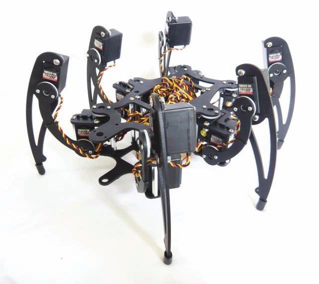
5 MSR-H01 Hexapod Assembly Guide Updated: 18-Aug-2008 Read first: Safety First! Read first: Servo Preparation Guide Properly identify all screws, washers, stand-offs and hardware etc. and gather together those necessary for each step. Carefully read and study the drawings prior to each assembly. Print this 6 page document with the following settings: Paper A4 or Letter, Margins 0.4", Scale 66%. tested in IE7 & Firefox Index Coxa Bottom Plate Assembly MSR-H01_ASSY01 Coxa Top Plate Assembly MSR-H01_ASSY02 Coxa Top Plate & Servo Assembly MSR-H01_ASSY03 Coxa & Femur Servo Assembly MSR-H01-ASSY04 Tibia Plate & Servo Assembly MSR-H01-ASSY05 Right Leg Finish Assembly MSR-H01-ASSY06 Left Leg Assembly MSR-H01-ASSY07 Lower Body Assembly MSR-H01-ASSY08 Upper Body Assembly MSR-H01-ASSY09 p.brain-smb Circuit Board Installation Leg & Body Attachment Assembly MSR-H01-ASSY10 Lower Body Attachment Assembly MSR-H01-ASSY11 Appendix A - Assembly Hardware Appendix B - Aluminum Leg Parts Appendix C - Aluminum Body Parts MSR-H01 Right Leg Assembly Coxa Bottom Plate Assembly MSR-H01_ASSY MSR-H01-COXA02 MSR-H01 Coxa Bottom Plate 2 1 MSR-P004 M3 x 16 Hexagon Socket Button Head 3 1 MSR-P013 M3 Hex Full Nut 4 1 MSR-P005 9 x 6mm Round Zinc Plated Brass Spacer Assemble as per diagram, pay attention to coxa bottom plate orientation. Coxa Top Plate Assembly MSR-H01_ASSY MSR-H01-COXA01 MSR-H01 Coxa Top Plate 2 2 MSR-P001 M3 x 40mm F-F Steel Hexagonal Spacer 3 2 MSR-P007 M3 x 10 Hexagon Socket Button Head 4 2 MSR-P014 M3 Plain Washer Assemble as per diagram, pay attention of coxa top plate orientation. When using HS-645MG servos for the femur joint, the M3 washer part (4) must be fitted. If using 40mm standard case size servos such as HS-985MG, do not fit part (4).
6 Coxa Top Plate & Servo Assembly MSR-H01_ASSY MSR-H01-ASSY02 MSR-H01 Coxa Assembly 2 2 MSR-P006 M4 x 10 Hexagon Socket Button Head 3 2 MSR-P012 M4 Hex Full Nut 4 1 MSR-HS225BB/MG Hitec HS-225BB or HS-225MG Servo 5 1 MSR-HSH24 Hitec 24mm Servo horn (from HS-225 servo) 6 1 MSR-HSSST Hitec Servo horn screw (from HS-225 servo) The servo horn (5) must be removed in order to fit the coxa servo (4). Take care not to rotate the servo spline when unscrewing the horn retaining screw (6). After the servo (4) has been fitted, replace the horn (5) in the same position. Having re-fitted your servo horn, I strongly recommend that you re-check your coxa servo is still centered: Servo Preparation Guide Pay attention to the servo orientation, the servo horn is at the end closest to the hexagonal spacers. Coxa & Femur Servo Assembly MSR-H01-ASSY MSR-H01-ASSY01 MSR-H01 Coxa assembly 2 2 MSR-P007 M3 x 10 Hexagon Socket Button Head 3 1 MSR-H01-ASSY02 MSR-H01 Coxa assembly 4 1 MSR-HS645MG Hitec HS-645MG Servo Insert the femur servo (4) into the top coxa plate slot as shown with the servo horn towards the bottom coxa plate. Tibia Plate & Servo Assembly MSR-H01-ASSY MSR-H01-TIBIA MSR-H01 Tibia plate 2 2 MSR-P006 M4 x 10 Hexagon Socket Button Head 3 2 MSR-P012 M4 Hex Full Nut 4 1 HS-645MG Hitec HS-645MG Servo Assemble as per diagram, pay attention to the servo orientation, the servo horn is closest to the foot of the tibia.
7 Right Leg Finish Assembly MSR-H01-ASSY MSR-H01-ASSY04 MSR-H01 Coxa assembly 2 1 MSR-H01-FEMUR MDR-H01 Femur plate 3 4 MSR-P008 N0.2 x 6.4mm Self tapping screw 4 1 MSR-H01-ASSY05 MSR-H01 Tibia assembly Take great care when fitting self tapping screws (3). Use the correct size phillips screw driver to avoid slipping or damaging the screw head. Once fitted the servo horn should fit flush with the femur plate, if this is not the case, back the screws (3) off a couple of turns and then re-tighten. Fit the screws into the middle of the single row of three holes on the horn indicated below (A) & (B). Although not necessary, the servo horn screw holes can be enlarged using a 1.5mm or 1/16" drill bit for easier screw installation. You will need to build three right legs for your hexapod, so repeat steps 1 to 6 until all right legs are complete. MSR-H01 Left Leg Assembly Left Leg Assembly MSR-H01-ASSY07 You will need to assemble three left legs for your hexapod. As for the right leg, follow steps 1 to 6, however, build the left leg as a mirror of the right leg assembly. To ensure you get your coxa plate orientation correct, take a good look at the left leg pictures below and left.
8 MSR-H01 Body Plate Assemblies Lower Body Assembly MSR-H01-ASSY MSR-H01-BODY02 MSR-H01 Lower Body Plate 2 6 MSR-P011 M6 x 4mm Insulation Washer 3 4 MSR-P x 3.5mm Stick-on Rubber Bumper First insert the insulation washers (2) into the lower body plate, you may find these should insert easier on one side of the body. Now turn the body over and mount the stick-on rubber bumpers in locations shown below. Upper Body Assembly MSR-H01-ASSY MSR-H01-BODY01 MSR-H01 Upper Body Plate 2 4 MSR-P003 M3 x 60mm F-F Steel Hex Spacer 3 4 MSR-P002 M3 x 30mm F-F Nylon hex Spacer 4 8 MSR-P007 M3 x 10mm Hexagon Socket Button Head Assemble the upper body plate as per the diagram to the left, if required move to (9b) to fit the optional p.brain-smb circuit board. p.brain-smb Circuit Board Installation 1 1 MSR-H01-ASSY10 MSR-H01 Assembly 2 4 MSR-P007 M3 x 10mm Hexagon Socket Button Head 3 1 p.brain-smb p.brain-smb Circuit Board Fit the p.brain-smb as shown in the diagram, if you have a battery switch harness, its a good idea to fit it now.
9 MSR-H01 Final Assembly Leg & Body Attachment Assembly MSR-H01-ASSY MSR-H01-ASSY09 MSR-H01 Body Assembly 2 3 MSR-H01-ASSY06 MSR-H01 Right Leg Assembly 3 3 MSR-H01-ASSY07 MSR-H01Left Leg Assembly 4 12 MSR-P008 N0.2 x 6.4mm Self tapping screw Attach right and left legs as shown in the diagram below and exploded detail left. Take great care when fitting self tapping screws (3). Use the correct size phillips screw driver to avoid slipping or damaging the screw head. Once fitted the servo horn should fit flush with the femur plate, if this is not the case, back the screws (3) off a couple of turns and then re-tighten. Fit the screws into the middle of the single row of three holes on the horn indicated left (A) & (B). Lower & Upper Body Attachment Assembly MSR-H01-ASSY MSR-H01-ASSY11 MSR-H01 Assembly 2 1 MSR-H01-ASSY09 MSR-H01 Lower Body Assembly 3 4 MSR-P007 M3 x 10mm Hexagon Socket Button Head 4 6 MSR-P009 Rubber End Cap M5 x 13mm Slide the bottom plate assembly (2) over the coxa bearings and fix in place. Add rubber end caps (4) to tarsus feet. This completes the MSR-H01 assembly.
10 You now need to spend some time carefully routing the servo cables back to the control electronics. The way in which the cables are routed very much depends on the electronics used and personal preference. You may use small cable ties or expandable cable sleeving to tidy servo leads. When you have routed and cable tied the servo leads, make sure the legs have room to rotate through their operational range without pulling or pinching any cables.
11 Appendices Appendix A Assembly Hardware Assembly Hardware 1 12 MSR-P001 M3 x 40mm F-F Steel Hexagonal Spacer 2 4 MSR-P002 M3 x 30mm F-F Nylon hex Spacer 3 4 MSR-P003 M3 x 60mm F-F Steel Hex Spacer 4 6 MSR-P005 9 x 6mm BZP Brass Round Spacer 5 6 MSR-P011 M6 x 4mm Nylon Insulation Washer 6 6 MSR-P004 M3 x 16mm Stainless Steel Hexagon Socket Button Head 7 42 MSR-P007 M3 x 10mm Stainless Steel Hexagon Socket Button Head 8 25 MSR-P006 M4 x 10mm Stainless Steel Hexagon Socket Button Head 9 38 MSR-P008 N0.2 x 6.5mm BZP Steel Self tapping screw 10 7 MSR-P013 M3 BZP Steel Hex Full Nut MSR-P012 M4 BZP Steel Hex Full Nut MSR-P014 M3 BZP Steel Plain Washer 13 4 MSR-P x 3.5mm Stick-on Rubber Bumper 14 6 MSR-P009 M5 x 13mm Rubber End Cap Appendix B Aluminum Leg Parts Aluminum Leg 1 6 MSR-H01-COXA01 MSR-H01 Coxa Top Plate 2 6 MSR-H01-COXA02 MSR-H01 Coxa Bottom Plate 3 6 MSR-H01-FEMUR MSR-H01 Femur 4 6 MSR-H01-TIBIA MSR-H01 Tibia Appendix C Aluminum Body Parts Aluminum Body 1 1 MSR-H01-BODY01 MSR-H01 Body Upper Plate 2 1 MSR-H01-BODY02 MSR-H01 Body Lower Plate
3DOF Leg Kit Assembly Guide VERSION 1.0
 3DOF Leg Kit Assembly Guide VERSION 1.0 WARRANTY CrustCrawler warrants its products against defects in materials and workmanship for a period of 30 days. If you discover a defect, CrustCrawler will, at
SeeMeCNC Guides. Step 2. REV2 Rostock Max v3 Base Assembly. Second edition Rostock Max v3 assembly guide. Written By: JJ Johnson
 SeeMeCNC Guides Step 2. REV2 Rostock Max v3 Base Assembly Second edition Rostock Max v3 assembly guide. Written By: JJ Johnson INTRODUCTION This assembly guide will walk you though the steps of assembly
Stainless Steel Bench Stand
 Installation Manual Stainless Steel Bench Stand Product(s): 29600 29601 51229 2016 by Fairbanks Scales, Inc. Revision 2 02/16 All rights reserved. Amendment Record STAINLESS STEEL BENCH STAND Document
INSTALLATION INSTRUCTIONS ATV WINCH MULTI-MOUNT Multi-Mount Mounting-Kit: PN Application: YAMAHA BIGBEAR 00+
 INSTALLATION INSTRUCTIONS ATV WINCH MULTI-MOUNT Multi-Mount Mounting-Kit: PN 61025 Application: YAMAHA BIGBEAR 00+ Your safety, and the safety of others, is very important. To help you make informed decisions
INSTALLATION INSTRUCTIONS
 INSTALLATION INSTRUCTIONS SNYPER TUBULAR FENDERS APPLICATION: 2007-2017 Jeep Wrangler JK PART NUMBER: 62-1005, 62-1015 ITEM QUANTITY DESCRIPTION TOOLS NEEDED 1,2 2 FRONT FENDERS, DRIVER (1) AND PASSENGER
The Mind Project s Iris 1 Robotic Arm. Packing List Assembly instructions
 The Mind Project s Iris 1 Robotic Arm Packing List Assembly instructions Packing list Below you will find pictures and descriptions of each part. It may be helpful to take each piece out of the bag and
LC6X4WTM Security Wall Mount with Tilt for up to 60" Flat Screens with VESA 600mm x 400mm or less
 Page 1 of 6 The LC6X4WTM Security Wall Mount with Tilt is designed to secure a flat screen, up to a 60", to the wall while still allowing the monitor to tilt. The VESA mounting patterns on the front of
INSTALLATION INSTRUCTIONS
 INSTALLATION INSTRUCTIONS SPORTSMAN WINCH MOUNT GRILLE GUARD APPLICATION: 2016-2018 Toyota Tacoma PART NUMBER: 40-93885, 45-93880, 46-23885 ITEM QUANTITY DESCRIPTION TOOLS NEEDED 1 1 WINCH TRAY 15MM SOCKET
The Mind Project s Iris 1 Robotic Arm. Assembly instructions Step 1
 The Mind Project s Iris 1 Robotic Arm Assembly instructions Step 1 Packing list Below you will find pictures and descriptions of each part. It may be helpful to take each piece out of the bag and place
Assembly Instructions and Parts Manual JPSF-1 Fence and JPSR Rail Set #
 Assembly Instructions and Parts Manual JPSF-1 Fence and JPSR Rail Set #1002493 JET 427 New Sanford Road LaVergne, Tennessee 37086 Part No. M-708482 Ph.: 800-274-6848 Revision C3 02/2014 www.jettools.com
INSTALLATION INSTRUCTIONS
 INSTALLATION INSTRUCTIONS R5 STEP BOARD APPLICATION: 2009-2017 Dodge Ram 1500 Quad / Crew Cab 2010-2017 Dodge Ram 2500/3500 Crew Cab PART NUMBER: 28-51040, 28-51045, 28-51050, 28-51055 ITEM QUANTITY DESCRIPTION
ADDICTIVE DESERT DESIGNS
 Preparation: Disconnect the negative battery terminal. Park the vehicle on level ground and set the emergency brake. We recommend reading through the installation instructions in whole before performing
BX Honda Accord Ex-L 2012 Honda Accord SE Installation Instructions
 Please read BOTH these and the General Instructions before attempting to install or operate this equipment. Serial Number 1. Blue Ox towing products and accessories are intended to be installed by Blue
Ribcage Installation. Part 2 - Assembly. Back-Bone V1.06
 Ribcage Installation Part 2 - Assembly Back-Bone V1.06 Contents Section 1 Before You Get Started... 2 Included With Your Kit:... 2 Figure: A... 3 CAUTION!... 4 Note:... 4 Tools Required... 5 Section 2:
INSTALLATION & OPERATING INSTRUCTIONS. REDCO LETTUCE KING I and LETTUCE KING IV
 INSTALLATION & OPERATING INSTRUCTIONS for REDCO LETTUCE KING I and LETTUCE KING IV Lettuce King I Shown with optional Drum Ring Lettuce King IV TO BE SERVICED ONLY BY AUTHORIZED PERSONS P/N: 2802381 REV:
LCD MONITOR/TV WALL MOUNT
 INSTALLATION INSTRUCTIONS LCD MONITOR/TV WALL MOUNT DUAL DESK CLAMP (RFCD-110) S CAUTION CAUTION A alerts you to the possibility of serious injury or death if you do not follow the instructions. A CAUTION
INSTALLATION INSTRUCTIONS Small Flat Panel FMA Pivot Arrays Models: FMA-220 and FMA-320
 INSTALLATION INSTRUCTIONS Small Flat Panel FMA Pivot Arrays The FMA-220 and FMA-320 pivot array allow both horizontal and vertical display pitch adjustment. The pitch adjustment range is 30 (15 up / 15
Assembly Instructions and Parts Manual JPSF-1 Fence and JPSR Rail Set
 Assembly Instructions and Parts Manual JPSF-1 Fence and JPSR Rail Set WALTER MEIER (Manufacturing) Inc. 427 New Sanford Road LaVergne, Tennessee 37086 Part No. M-708482 Ph.: 800-274-6848 Revision C2 02/2013
GlideRite Retractable Cover System For Hot Spot Spas (SE & SLX only)
") List of Contents Quantity Description 12 #10 x 1 ½ Flat Head Phillips Screw (see pg. 2) 2 #10 x ½ Pan Head Phillips Screw (see pg. 2) 8 ¼ x 2 ½ Lag Bolt (see pg. 2) 7 ¼ 20 x 5 / 8 Hex Head Bolt (see pg.
List of Contents Quantity Description 12 #10 x 1 ½ Flat Head Phillips Screw (see pg. 2) 2 #10 x ½ Pan Head Phillips Screw (see pg. 2) 8 ¼ x 2 ½ Lag Bolt (see pg. 2) 7 ¼ 20 x 5 / 8 Hex Head Bolt (see pg.
RC Interface Controller Board Assembly and Operation
 RC Interface Controller Board Assembly and Operation Revision Date: January 17, 2006 SUPERDROIDROBOTS.COM RC Interface Controller Board Accurate content is of the utmost importance to the authors of this
INSTALLATION INSTRUCTIONS
 PART NO. 911000T 911000PS 915000T 915000PS PRODUCT DESCRIPTION: Sport Bar 2.0, Full size Textured Black Sport Bar 2.0, Full size Polished Stainless Steel Tubes Sport Bar 2.0, Mid size Textured Black PRODUCT
2015 Current Ford F150/Raptor Adaptive Cruise Control Module Relocation Bracket Installation Instructions
 2015 Current Ford F150/Raptor Adaptive Cruise Control Module Relocation Bracket Installation Instructions PREPARATION 1. Disconnect the negative terminal on the battery. Park the vehicle on level ground
GlideRite Retractable Cover System For HotSpring & Tiger River Spas (except Classic & pre-2000 Landmark Spas)
") List of Contents Quantity Description 12 #10 x 1 ½ Flat Head Phillips Screw (see pg. 2) 2 #10 x ½ Pan Head Phillips Screw (see pg. 2) 8 ¼ x 2 ½ Lag Bolt (see pg. 2) 7 ¼ 20 x 5 / 8 Hex Head Bolt (see pg.
List of Contents Quantity Description 12 #10 x 1 ½ Flat Head Phillips Screw (see pg. 2) 2 #10 x ½ Pan Head Phillips Screw (see pg. 2) 8 ¼ x 2 ½ Lag Bolt (see pg. 2) 7 ¼ 20 x 5 / 8 Hex Head Bolt (see pg.
Arc Trainer Main Frame Assembly
 Arc Trainer Main Frame Assembly Kit No. 610AK019-4 Kit No. 630AK019-4 NOTE: This instruction sheet describes how to replace the main frame assembly in the Arc Trainer 610A. Tools Required 3/16 Allen wrench
SawStop. Contractor Fence Assembly OWNER S MANUAL. Model CNS-SFA
 Contractor Fence Assembly OWNER S MANUAL Model CNS-SFA Warranty warrants to the original retail purchaser of the Contractor Fence Assembly accompanying this manual that the fence assembly will be free
LC200WT Security Wall Mount with Tilt for up to 32" Flat Screens
 Page 1 of 6 The LC200WT Security Wall Mount with Tilt is designed to secure up to a 32" flat panel monitor to the wall while still allowing the monitor to tilt. The VESA mounting patterns on the front
installation guide 1 GUIDE#: PWB-wwpontoon-pol-004
 f250 pontoon WAKEBOARD tower installation guide INSTALLATION SUPPORT 1 important information This WakeWorks tower fits Pontoon boats with 96 to 102 inch wide beam widths. This measurement is taken from
INSTALLATION MANUAL WEEKENDER STEEL LADDER RACK
 TRUCK STORAGE SOLUTIONS SECURING YOUR REPUTATION INSTALLATION MANUAL WEEKENDER STEEL LADDER RACK STEEL & ALUMINUM SIDE BOX WITH PACK RAT DRAWER UNITS MODELS ATTENTION: PLEASE READ AND UNDERSTAND ALL INSTRUCTIONS
3DR ArduCopter Quad-C
 3DR ArduCopter Quad-C 3DR ArduCopter Quad-C Thank you for purchasing a 3DR ArduCopter Quad kit. The 3DR ArduCopter Quad is a stable and supported multi-rotor frame in the ongoing development of the ArduCopter
LEG CURL IP-S1315 INSTALLATION INSTRUCTIONS
 LEG CURL IP-S35 INSTALLATION INSTRUCTIONS Copyright 2009. Star Trac by Unisen, Inc. All rights reserved, including those to reproduce this book or parts thereof in any form without first obtaining written
INSTALLATION INSTRUCTION ATV BUMPER/WINCH MOUNT Mount Kit: PN Application: POLARIS 300, 400, 500 and 700 Sportsman
 INSTALLATION INSTRUCTION ATV BUMPER/WINCH MOUNT Mount Kit: PN 68573 Application: POLARIS 300, 400, 500 and 700 Sportsman Your safety, and the safety of others, is very important. To help you make informed
Please read BOTH these Installation Instructions and the General Instructions prior to installing or operating this equipment.
 Attachment Tab Height: 16-1/2 Serial Number Attachment Tab Width: 24 Please read BOTH these and the General Instructions prior to installing or operating this equipment. 1. Blue Ox towing products and
INSTRUCTION BOOKLET #34. For Wallbed models: KING SIZE SIERRA WITH STORAGE HEADBOARD
 For Wallbed models: KING SIZE SIERRA WITH STORAGE HEADBOARD INSTRUCTION BOOKLET #34 WARNING! ALL MURPHY/WALLBED SYSTEMS CONTAIN STORED ENERGY. FAILURE TO USE AND FOLLOW THESE INSTRUCTIONS DURING THE INSTALLATION
SAFETY THIS PRODUCT IS FOR OFFROAD USE ONLY. ALL LIABILITY FOR INSTALLATION AND USE RESTS WITH THE OWNER.
 SAFETY Your safety and the safety of others is very important. In order to help you make informed decisions about safety, we have provided installation instructions and other information. These instructions
VIEWPOINT ALUMINUM RUNNING BOARD TOYOTA RAV4
 PARTS LIST: VIEWPOINT ALUMINUM RUNNING BOARD 1 Driver/Left Running Board 4 10-1.5mm x 50mm T-Bolt 1 Passenger/Right Running Board 12 10mm Plastic Retainers 1 Driver/Left Bracket 2 10-1.50mm x 40mm Hex
FLOE DOCK FURNITURE WARNING ASSEMBLY INSTRUCTIONS
 FLOE DOCK FURNITURE ASSEMBLY INSTRUCTIONS KIT P/N 510-00400-02 KIT P/N 510-00405-02 KIT P/N 510-00406-02 KIT P/N 510-00410-02 WARNING IT IS THE INSTALLER S RESPONSIBILITY TO PROPERLY INSTALL this chair
Please read BOTH these Installation Instructions and the General Instructions prior to installing or operating this equipment.
 Attachment Tab Height: 16-1/4 Attachment Tab Width: 21-3/4 Please read BOTH these and the General Instructions prior to installing or operating this equipment. Serial Number 1. Blue Ox towing products
TRAKFAST REPAIR MANUAL DANGER TOOL DISASSEMBLY ALWAYS TAKE THE FOLLOWING PRECAUTIONS BEFORE ANY SERVICE OR ROUTING MAINTENANCE IS PERFORMED:
 DANGER ALWAYS TAKE THE FOLLOWING PRECAUTIONS BEFORE ANY SERVICE OR ROUTING MAINTENANCE IS PERFORMED: REMOVE FASTENERS REMOVE FUEL CELL REMOVE BATTERY REMOVE THE MAGAZINE ASSEMBLY Loosen and remove knob
Hatchback Wing Riser Kit
 Hatchback Wing Riser Kit 2015-06-11 Thank you for purchasing this PERRIN product for your car! Installation of this product should only be performed by persons experienced with installation of aftermarket
GLGS100 & OWNER S MANUAL V. GLGS
 GLGS100 Assembly & Instructions OWNER S MANUAL V. GLGS100-102914 W a r n i n g, S a f e t y & M a i n t e n a n c e Be sure that all users carefully read and understand all warning, safety and maintenance
TAILGATE SPREADER MATERIAL SAVER SYSTEM INSTALLATION & OPERATION MANUAL (TGS 300, TGS 600, & TGS 1100) TGS11328
 TGS11328") TAILGATE SPREADER MATERIAL SAVER SYSTEM INSTALLATION & OPERATION MANUAL (TGS 300, TGS 600, & TGS 1100) TGS11328 TABLE OF CONTENTS WARNINGS & CAUTIONS... 2 MATERIAL SAVER SYSTEM PARTS LIST... 3 EXISTING
TAILGATE SPREADER MATERIAL SAVER SYSTEM INSTALLATION & OPERATION MANUAL (TGS 300, TGS 600, & TGS 1100) TGS11328 TABLE OF CONTENTS WARNINGS & CAUTIONS... 2 MATERIAL SAVER SYSTEM PARTS LIST... 3 EXISTING
INSTRUCTIONS INSTRUCCIONES CONSIGNES
 AUTOMOTIVE PRODUCTS, INC. INSTRUCTIONS INSTRUCCIONES CONSIGNES APPLICATION: 2007-2010 CHEVY/GMC SILVERADO/SIERRA 2500/3500 (EXCLUDES CLASSIC) APP PART #46-23715, 40-92315/45-92310 MAX WINCH TRAY, SPORTSMAN
RATCHET CABLE CUTTER
 OPERATION, SERVICE AND PARTS INSTRUCTION MANUAL 764 RATCHET CABLE CUTTER Read and understand this material before operating or servicing this equipment. Failure to understand how to safely operate this
INSTALLATION INSTRUCTIONS Medium Flat Panel Model MSP-SI1
 INSTALLATION INSTRUCTIONS Medium Flat Panel Model MSP-SI1 IMPORTANT! : The MSP-S11 Mount is designed for use with Sharp 45" LCD displays that have a 200mm x 200mm mounting pattern. IMPORTANT! : The mount
ABM International, Inc.
 ABM International, Inc. Lightning Stitch required 1 1.0: Parts List head and motor assembly (Qty. 1) Reel stand (Qty. 1) Needle bar frame clamp (Qty. 1) Motor drive (Qty. 1) 2 Cable harness with bracket
Assembly Instructions
 InTandem Table System November 20 InTandem Table System - Worksurface #4 x/" 4 wood screw power beam Tools Provided T-0 Extended Torx Driver T-25 Torx Driver Additional Tools Required Soft protective
OWNER S MANUAL AMERICA S PREMIER XXL SUPER RACKS XXL-2960 SUPER RACK/SMITH MACHINE XXL-2960 L 112 W 86 H 100 XXL-2960 / XXL-912 L 179 W 91 H 100
 OWNER S MANUAL XXL-60 L 11 W 6 H 100 XXL-60 SUPER RACK/SMITH MACHINE XXL-60 / XXL-1 L 1 W 1 H 100 AMERICA S PREMIER XXL SUPER RACKS XXL-60 Rev0 Revision Date -1-07 COLOR CHART GRAY= SUB-ASSEMBLY PARTS
Assembly Instructions 10 X 10 Aluminum Frame Building
 Assembly Instructions 10 X 10 Aluminum Frame Building 27 97 9 8 47 36 74 52 10 10 X 10 Square Building W/ Dome Includes: The Steel Entry Door with a Dead Bolt Lock assembly and Aluminum Door Frame. Metal
(2) Plastic Plugs (2) Frame Bracket. Spacers. License Plate Bracket. (2) 12mm Single Bolt Plates. (2) 12mm Double Bolt Plates
 Plastic Plugs (2) Frame Bracket. Spacers. License Plate Bracket. (2) 12mm Single Bolt Plates. (2) 12mm Double Bolt Plates") LDB-CSIL26-FB PARTS LIST: 1 LD1 Bumper Assembly 10 12mm Hex Nuts 1 Driver/left Frame Mounting 6 10-1.5mm x 35mm Hex Bolts 1 Passenger/right Frame Mounting 12 10mm x 27mm OD x 3mm Flat Washers 2 Spacers
LDB-CSIL26-FB PARTS LIST: 1 LD1 Bumper Assembly 10 12mm Hex Nuts 1 Driver/left Frame Mounting 6 10-1.5mm x 35mm Hex Bolts 1 Passenger/right Frame Mounting 12 10mm x 27mm OD x 3mm Flat Washers 2 Spacers
INSTRUCTION BOOKLET #C21. For Wallbed models: KING SIZE
 For Wallbed models: KING SIZE INSTRUCTION BOOKLET #C1 WARNING! ALL MURPHY/WALLBED SYSTEMS CONTAIN STORED ENERGY. FAILURE TO USE AND FOLLOW THESE INSTRUCTIONS DURING THE INSTALLATION PROCESS COULD RESULT
TURBO DRIVE INSTALLATION MODEL 1582T KNEE FEED Lagun Mill
 TURBO DRIVE INSTALLATION MODEL 1582T KNEE FEED Lagun Mill NOTE This Turbo Drive Knee Feed is configured for mounting the feed on the front of the knee with the keypad facing left. The lead screw pitch
Aluminum frame packing list of Smart Laser CO2
 Aluminum frame packing list of Smart Laser CO2 1 805mm V-slot 20mm*40mm 1 2 780mm V-slot 20mm*40mm 2 3 860mm Aluminum frame 20mm*40mm 3 4 177mm Aluminum frame 20mm*40mm 1 5 85mm Aluminum frame 20mm*40mm
Western Products, PO Box , Milwaukee, WI MOUNT KIT. Model No Ford F-150 4X
 Western Products, PO Box 245038, Milwaukee, WI 53224-9538 www.westernplows.com November 1, 2009 Lit. No. 64461, Rev. 05 64500 MOUNT KIT Model No. 3239 Ford F-150 4X4 2004-08 Installation Instructions Read
PHTM200 - Phantom 200 Flat Screen Wall Mount with Wafer Thin Projection Fits Screens up to 50 lbs with 200mm Mounting Patterns
 PHTM200 - Phantom 200 Flat Screen Wall Mount with Wafer Thin Projection Fits Screens up to 50 lbs with 200mm Mounting Patterns Features: Durable high quality gloss black baked on powder coat finish Fits
Diva Acoustical Ceiling
 Installation Instructions Diva Acoustical Ceiling CONTENTS Important User Information...........................2 Safety Precautions.................................3 Required Tools....................................3
Droplit v2 Frame Assembly
 SeeMeCNC Guides Droplit v2 Frame Assembly Droplit v2 Frame Assembly Written By: JJ Johnson 2017 seemecnc.dozuki.com Page 1 of 22 Step 1 Droplit v2 Frame Assembly Locate the Projector Plate, Projector Joining
General Features. Low Profile. The SMART BOXX stands only 1.5 off of the bed of your truck so cargo space is maximized
 General Features Low Profile. The SMART BOXX stands only 1.5 off of the bed of your truck so cargo space is maximized Two Sizes Short Box :74 L X 47 W X 7 T and Long Box 92 L X 47 W X 7 T All Aluminium
OpenROV. Guide 3 - Electronics. We will now move to the assembly of the electronics that will control the ROV. Written By: OpenROV
 OpenROV Guide 3 - Electronics We will now move to the assembly of the electronics that will control the ROV. Written By: OpenROV 2017 openrov.dozuki.com Page 1 of 33 INTRODUCTION We will introduce soldering
MOUNT KIT. Ford F-150 4X Installation Instructions CAUTION. Read this document before installing the snowplow. CAUTION
 December 1, 2014 Lit. No. 64461, Rev. 06 64500 MOUNT KIT Ford F-150 4X4 2004-08 Installation Instructions Read this document before installing the snowplow. See your sales outlet/web site for specific
Nancy s Knit Knacks LLC 4 Yard Option Upgrade Kit Assembly Instructions and User Manual
 Nancy s Knit Knacks LLC 4 Yard Option Upgrade Kit Assembly Instructions and User Manual Thank you for purchasing our 4 Yard Option (4YO) Upgrade Kit. To install this upgrade you are simply going to assemble
Strata. urniture. Adriana Instructions. Parts in the Arm Box: Parts in the Body Box: Watch our assembly videos at
 1A Watch our assembly videos at www.strataf.com/videos Parts in the Arm Box: Arm - Outside View Arm - Inside View 1B Parts in the Body Box: Back Deck x 1 Seat Deck x 1 with the Feet attached Back Panel
Please read BOTH these Installation Instructions and the General Instructions before attempting to install or operate this equipment.
 Please read BOTH these and the General Instructions before attempting to install or operate this equipment. 1. Blue Ox towing products and accessories are intended to be installed by Blue Ox Dealers who
WESTERN PRODUCTS, P.O. BOX , MILWAUKEE, WI MOUNT KIT. Ford Super Duty F250/350/450/
 WESTERN PRODUCTS, P.O. BOX 245038, MILWAUKEE, WI 53224-9538 www.westernplows.com October 1, 2007 Lit. No. 64680, Rev. 03 33259 MOUNT KIT Ford Super Duty F250/350/450/550 2005-07 Installation Instructions
INSTALLATION INSTRUCTIONS Small Flat Panel Mounts Model: F-Series
 INSTALLATION INSTRUCTIONS Small Flat Panel Mounts Model: F-Series This Instruction Manual covers most of the F-Series wall and desk mounts, as well as selected F-Series pole mounts. NOTE: Some F-Series
BABY WOLF LOOM. Assembly Instructions for Knocked-Down Looms
 BABY WOLF LOOM Assembly Instructions for Knocked-Down Looms BEFORE YOU BEGIN Please read through the directions before beginning to assemble your loom. Unpack the loom parts carefully. Do not throw away
INSTRUCTION BOOKLET #C20
 INSTRUCTION BOOKLET #C0 WARNING! ALL MURPHY/WALLBED SYSTEMS CONTAIN STORED ENERGY. FAILURE TO USE AND FOLLOW THESE INSTRUCTIONS DURING THE INSTALLATION PROCESS COULD RESULT IN SEVERE PERSONAL INJURY TO
IMPORTANT SAFETY INSTRUCTIONS: -We strongly recommend that a professional electrician install all direct wire fixtures.
 PRODUCT NAME: Mimi Quatrefoil Ceiling Mount ITEM NUMBER: LM199 BRA 1016 DIMENSIONS OF ITEM ASSEMBLED: 10 1/2 H x 15 1/2 DIA IMPORTANT SAFETY INSTRUCTIONS: -We strongly recommend that a professional electrician
Installing the Partridge RA Extension on Losmandy G11
 Installing the Partridge RA Extension on Losmandy G11 Michael Herman July 20, 2015 Tools: 3/16 inch hex key (allen wrench) [If desired for DEC indicator ring friction improvement: flat screwdriver, and
ADDICTIVE DESERT DESIGNS
 Preparation: Disconnect the negative battery terminal. Park the vehicle on level ground and set the emergency brake. We recommend reading through the installation instructions in whole before performing
RZ 200 Parts Diagram. To avoid confusion during installation remove this page and router being installed pages, return others to box.
 Collar Page 1 To avoid confusion during installation remove this page and router being installed pages, return others to box. Caution: Before and during installation of Router Raizer make sure power switch
model tsa-sa48 Sliding Crosscut Table installation guide
 model tsa-sa48 Sliding Crosscut Table installation guide A Note About Color Variations Among Anodized Aluminum Components Congratulations on the purchase of this SawStop Sliding Crosscut Table. We at SawStop
Single Band 125mm Profile Panel Antennas Installation and Operation Instructions Including APM-F-084-S4 & APM-T-085-S4 Mounting Kits
 General Single Band 125mm Profile Panel Antennas Installation and Operation Instructions Including APM-F-084-S4 & APM-T-085-S4 Mounting Kits This instruction sheet contains all necessary information required
 INSTRUCTION BOOKLET #C10 Watch step by step installation instructions at: https://www.wallbedsbywilding.com/wallbed-installation-studio-series/ WARNING! ALL MURPHY/WALLBED SYSTEMS CONTAIN STORED ENERGY.
Please read BOTH these Installation Instructions and the General Instructions before attempting to install or operate this equipment.
 Please read BOTH these and the General Instructions before attempting to install or operate this equipment. 1. Blue Ox towing products and accessories are intended to be installed by Blue Ox Dealers who
INSTALLATION GUIDE PREMIUM FRONT BUMPER. AEV30103AE Last Updated: 09/08/14 US PATENTS: D683281, D CHINESE PATENT: ZL
 PREMIUM FRONT BUMPER US PATENTS: D683281, D697842 CHINESE PATENT: ZL 2012 3 0026081.4 AEV30103AE Last Updated: 09/08/14 INSTALLATION GUIDE PLEASE READ BEFORE YOU START TO GUARANTEE A QUALITY INSTALLATION,
SIGNATURE FRONT BUMPER INSTALL
 SIGNATURE FRONT BUMPER INSTALL JL **PLEASE READ THROUGH THE INSTRUCTIONS BEFORE BEGINNING ANY PART OF THE INSTALLATION PROCESS** 1. You can now remove the trim strip (2 vertical clips, 4 horizontal, 2
INSTALLATION INSTRUCTIONS
 INSTALLATION INSTRUCTIONS FCB Pinnacle 2 Flavor Emerson Units THERMOSTAT RESET UPGRADE KIT P/N 629088480 IMPORTANT: This procedure is intended for use by a Qualified Service Technician. IMPORTANT: This
OB1U INSTALLATION INSTRUCTIONS. Interactive Flat Panel Over White Board Mount
 INSTALLATION INSTRUCTIONS Interactive Flat Panel Over White Board Mount Spanish Product Description German Product Description Portuguese Product Description Italian Product Description Dutch Product Description
Read Below! Read Below! Read Below! Read Below! Read Below! Read Below! STOP READ TIPS BELOW TO MAKE ASSEMBLY MUCH EASIER
 Read Below! Read Below! Read Below! Read Below! Read Below! Read Below! STOP READ TIPS BELOW TO MAKE ASSEMBLY MUCH EASIER Here are some guidelines to help make assembling your unit much easier: -Read and
Installation and Assembly: Flat Video Wall Mount For 40" to 65" Flat Panel Displays
 Installation and Assembly: Flat Video Wall Mount For 40" to 65" Flat Panel Displays Model: DS-VW665 Maximum Load Capacity: 125 lb (57 kg) 1 of 11 ISSUED: 03-22-12 SHEET #: 125-9288-4 06-25-13 NOTE: Read
Star Trac Turbo Trainer Assembly & Setup
 Star Trac Turbo Trainer Use the following procedures to unpack and assemble your Turbo Trainer manufactured by Star Trac. UNPACKING AND PARTS LIST Position the shipping carton so the Heavy End logo is
MOUNT KIT. Ford Super Duty F 250/350/450/ Installation Instructions CAUTION. Read this document before installing the snowplow.
 November 15, 2014 Lit. No. 64680, Rev. 04 33259 MOUNT KIT Ford Super Duty F 250/350/450/550 2005-07 Installation Instructions Read this document before installing the snowplow. See your sales outlet/web
INSTALLATION INSTRUCTIONS WINCH MOUNTING PLATE FOR STOCK BUMPER Part Number: 88140, FOR 8274 Application: Jeep JK 2012+
 INSTALLATION INSTRUCTIONS WINCH MOUNTING PLATE FOR STOCK BUMPER Part Number: 88140, 88418 FOR 8274 Application: Jeep JK 2012+ GENERAL SAFETY PRECAUTIONS Your safety, and the safety of others, is very important.
OXYGEN INSTALLATION. Revision date
 12345 1 Hardware List 12345 Flat head wood screw #9 x 7/8 long with #2 Phillips drive, silver Used to attach surfaces and end panels Hex set screw ½-13 x 2 long with 1/4 hex drive, black Used on Legs Hex
WOLF PUP LOOM TM & WOLF PUP LT LOOM TM
 WOLF PUP LOOM TM & WOLF PUP LT LOOM TM Assembly Instructions FL3000 FL3006 FL3009 WOLF PUP WOLF PUP LT Find out more at schachtspindle.com Schacht Spindle Company 6101 Ben Place Boulder, CO 80301 p. 303.442.3212
RH-412 STEEL DOORS INSTALLATION INSTRUCTIONS
 RH-412 STEEL DOORS INSTALLATION INSTRUCTIONS By following the steps outlined below, the assembly, installation and adjustment of the steel doors, will be a simple process. Let s start with the Driver Side.
PRODUCT: LOKI INSTALLATION INSTRUCTIONS. Product is covered by U.S. patents. For more information visit
 R INSTALLATION INSTRUCTIONS PRODUCT: LOKI CONFIGURATION: SINGLE DOOR MOUNT: GLASS MOUNT Product is covered by U.S. patents. For more information visit www.krownlab.com . TOOLS + MATERIALS REQUIRED TOOLS
JK JEEP MIDWIDTH FRONT BUMPER
 SIGNATURE SERIES JK JEEP MIDWIDTH FRONT BUMPER INSTALLATION INSTRUCTIONS **PLEASE READ THROUGH THE INSTRUCTIONS BEFORE BEGINNING ANY PART OF THE INSTALLATION PROCESS** 1. Begin the installation of your
2010+ Dodge Ram 2500/3500 Front Bumper Install Instructions
 2010+ Dodge Ram 2500/3500 Front Bumper Install Instructions Warning! Read the instructions completely before beginning the installation. Before tightening bolts, drilling or cutting where required, check
ATTACH WALL PLATE TO WALL
 DANGER! The Elite ar m contains high p r e s s u r e g a s s p r i n g s. T h e following cautions MUST be observed to avoid serious injury. 1. Do not attempt to adjust your Elite arm until everything
INSTALLATION INSTRUCTIONS
 INSTALLATION INSTRUCTIONS Universal Low Profile Flat Mount Model: U.S. Toll Free: 1-866-752-6271 Outside N. America: 1-503-748-5799 E-mail: ts@planar.com FRANCE Phone: +33 5 6378 3810 E-mail: emeats@planar.com
Tilting Flat Panel Wall Mount Installation Guide
 Tilting Flat Panel Wall Mount Installation Guide Model: A580TM Easy installation Built-in level for easy positioning Safety bolts lock the TV on the mount Easy to adjust tilt angles: +5 to -15 degrees
C PART LIST HARDWARE LIST. Kitchen Cart IMPORTANT NOTE
 88 9200 006C Kitchen Cart IMPORTANT NOTE Carefully remove all the parts from the carton and put them individually on a soft cloth to prevent scratches or other damages occuring to the parts. We have taken
PATRIOT DOCKS ASSEMBLY INSTRUCTIONS
 6/1/2008 PATRIOT DOCKS ASSEMBLY INSTRUCTIONS Congratulations on your new Patriot Dock purchase. This manual contains instructions to assemble basic dock configurations for use at typical shoreline application.
HERCULES EXTENDED TOWER
 AmeriGlide Accessibility Solutions HERCULES EXTENDED TOWER ATION GUIDE Please read this installation guide carefully to ensure correct installation of the HERCULES EXTENDED TOWER Vertical Platform Lift.
10" E-Series D-Series - Pair. kit includes (14) (4) (4) It is strongly recommended that this product be installed by a professional.
 (4) (4) It is strongly recommended that this product be installed by a professional.") 2014 GMC 1500 grille installation instructions 10" E-Series D-Series - Pair kit includes (14) (14) (4) 5 /16-18x 5 /8 Button Socket 5 /16-18 Low Profile Nylock Nut M6-1.0x30mm Button Head Socket (14) (4)
2014 GMC 1500 grille installation instructions 10" E-Series D-Series - Pair kit includes (14) (14) (4) 5 /16-18x 5 /8 Button Socket 5 /16-18 Low Profile Nylock Nut M6-1.0x30mm Button Head Socket (14) (4)
Assembly Instructions 10 X 10 Aluminum Roof Support
 Assembly Instructions 10 X 10 Aluminum Roof Support Aluminum Roof Support Bolt Package 16-5/16 X 2 ¼ SS Bolt 24-5/16 X 1 SS Bolt 40-5/16 SS Nylon Lock Nuts 16-5/16 SS Flat Washers 28-4 ½ Wood Screws 36-1
https://www.wallbedsbywilding.com/wallbed-installation-studio-series/
 For Wallbed models: KING SIZE INSTRUCTION BOOKLET #C1 Watch step by step installation instructions at: https://www.wallbedsbywilding.com/wallbed-installation-studio-series/ WARNING! ALL MURPHY/WALLBED
LifeGear G1 /HOME GYM ITEM NO.: 63100
 LifeGear G1 /HOME GYM ITEM NO.: 63100 OWNER S MANUAL IMPORTANT: Read all instructions carefully before using this product. Retain this owner s manual for future reference. The specifications of this product
INSTALLATION INSTRUCTIONS 6 OVAL BENT END SIDEBARS DODGE RAM 1500, CREW CAB PART#: /241533B
 PARTS LIST: 1 Driver/Left Sidebar 24 8mm x 24mm x 2mm Flat Washers 1 Passenger/Right Sidebar 12 8mm Lock Washers 3 Driver/left, Passenger Center and Rear 6 8mm Hex Nuts 3 INSTALLATION INSTRUCTIONS 6 OVAL