Aspects of Achieving 10 v/m Field Uniformity over 1-6GHz with Single, Multiple and Cassegrain Antennas. Tom Mullineaux
|
|
|
- Daisy Wright
- 6 years ago
- Views:
Transcription
1 Aspects of Achieving 10 v/m Field Uniformity over 1-6GHz with Single, Multiple and Cassegrain Antennas Tom Mullineaux
2 EN Edition GHz, 10 3 meters
3 Field Generation Fundamentals
4 10v/m 1.5m 1.5m Test Field of a Prescribed Field Strength Across a Defined Plane
5 Equipment Under Test (EUT) One Face of EUT is Placed at the Plane EUT Is Monitored for Degradation in Performance when Exposed to Test Field Repeat for All Faces
6 Test Field Generation RF Input Power P Bore Sight Field E (v/m) Horn Antenna Gain G Test Plane Distance d
7 E = (30.P.G) / d Field Strength in v/m RF Power at Antenna Connector Gain of Antenna (Linear, not db) Distance from Antenna Fiddle Factor?
8 Area of Sphere 4πR 2 S = P/4πR 2 P Power Density S = E 2 /Z o S = E 2 /120π Impedance of Free Space Zo is 120π (377 Ohms)
9 P/4πR 2 = E 2 /120π E 2 = 120π.P / 4πR 2 E 2 = 30.P / R 2 E = (30.P) / R E = (30.P.G) / d
10 IMPLICATIONS P = d 2 E 2 / 30G RF Power Required at Antenna Connector Implication #1: Two Times the Gain Means HALF the RF Power is Required Implication #2: Double the Distance Means FOUR times the RF Power is Required Implication #3: Two Times the Field Strength Means FOUR times the RF Power is Required
11 Characteristics of High Gain / Low Gain Antennas
12 Test Plane Illumination Falls with Distance Bore Sight Max E(v/m)
13 Medium Gain Horn Illumination E/ 2 Bore Sight Max E(v/m) Beam Width (Degrees) E/ 2
14 High Gain Horn Illumination E/ 2 Bore Sight Max E(v/m) E/ 2 Beam Width (Degrees)
15
16
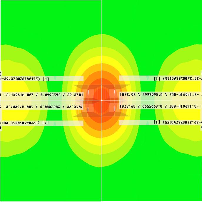
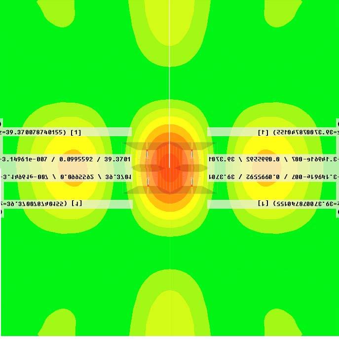
17 10v/m, -0dB, +6dB 1.5m 16 points all between 1.5m 10v/m and 20 v/m
18 Test Plane Illumination 16 points all between 10 and 20 v/m 10v/m, -0dB, +6dB Bore Sight
19 Effect of Higher Gain 16 points all between 10 and 20 v/m 10v/m, -0dB, +6dB Bore Sight
20 16 points all between 10 and 20 v/m 10v/m, -0dB, +6dB
21 16 points all between 10 and 20 v/m 10v/m, -0dB, +6dB
22 16 points all between 10 and 20 v/m 10v/m, -0dB, +6dB
23 16 points all between 10 and 20 v/m 10v/m, -0dB, +6dB
24 16 points all between 10 and 20 v/m 10v/m, -0dB, +6dB
25 16 points all between 10 and 20 v/m 10v/m, -0dB, +6dB
26 16 points all between 10 and 20 v/m 10v/m, -0dB, +6dB
27 16 points all between 10 and 20 v/m 10v/m, -0dB, +6dB
28 16 points all between 10 and 20 v/m 10v/m, -0dB, +6dB
29 EQUIVALENT TO??
30 Beam Width is Becoming Important - Some Standards Now Insist the EUT Fits Inside the Antenna Beam Width EUT Must Fit Here Half-Power Density = E/ 2 Emax
31 Advantages / Disadvantages of Each Antenna Type
32 High Gain Horn Advantage Reduced RF Power Requirement
33 High Gain Horn Advantage Reduced RF Power Requirement High Gain Horn Disadvantage Smaller Illumination Area
34 High Gain Horn Advantage Reduced RF Power Requirement High Gain Horn Disadvantage Smaller Illumination Area (equivalent?)
35 High Gain Horn Advantage Reduced RF Power Requirement High Gain Horn Disadvantage Smaller Illumination Area (equivalent?) Higher Field Contribution from Harmonic
36 Wanted Test Frequency Harmonic Signal, Un-Wanted Test Frequency
37 High Gain at Harmonic Frequency E/ 2 (-6dB) E (v/m) Measured Field is Sum of Wanted Field and Un-Wanted Field E/ 2 (-6dB)
38 High Gain Horn Advantage Reduced RF Power Requirement High Gain Horn Disadvantage Smaller Illumination Area (equivalent?) Higher Field Contribution from Harmonic
39 High Gain Horn Advantage Reduced RF Power Requirement High Gain Horn Disadvantage Smaller Illumination Area (equivalent?) Higher Field Contribution from Harmonic Less Bandwidth so More Antennas Required
40 High Gain Horn Advantage Reduced RF Power Requirement High Gain Horn Disadvantage Smaller Illumination Area (equivalent?) Higher Field Contribution from Harmonic Less Bandwidth so More Antennas Required Medium Gain Horn Advantage Large Illumination Area
41 High Gain Horn Advantage Reduced RF Power Requirement High Gain Horn Disadvantage Smaller Illumination Area (equivalent?) Higher Field Contribution from Harmonic Less Bandwidth so More Antennas Required Medium Gain Horn Advantage Large Illumination Area Less Field Contribution from Harmonic
42 High Gain Horn Advantage Reduced RF Power Requirement High Gain Horn Disadvantage Smaller Illumination Area (equivalent?) Higher Field Contribution from Harmonic Less Bandwidth so More Antennas Required Medium Gain Horn Advantage Large Illumination Area Less Field Contribution from Harmonic Wider Bandwidth, One Antenna Required
43 High Gain Horn Advantage Reduced RF Power Requirement High Gain Horn Disadvantage Smaller Illumination Area (equivalent?) Higher Field Contribution from Harmonic Less Bandwidth so More Antennas Required Medium Gain Horn Advantage Large Illumination Area Less Field Contribution from Harmonic Wider Bandwidth, One Antenna Required Medium Gain Horn Disadvantage Higher RF Power Requirement
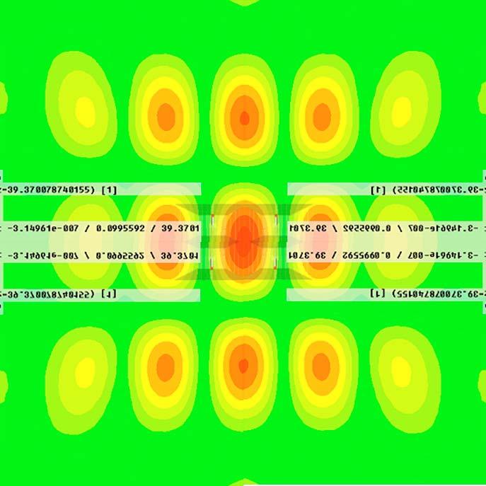
44 Field Uniformity Through Use of Multiple High-Gain Antennas
45 Multiple High-Gain Horn Illumination


46 HIRF Multiple Horn Illumination
47 16 points all between 10 and 20 v/m
48 16 points all between 10 and 20 v/m 14v/m 14v/m 10v/m 12v/m 10v/m 14v/m 14v/m One Test Run Only
49 EQUIVALENT TO??
50 Reduced Risk of Corona Effect Due to Power Sharing 200v/m
51

52
53
54

55

56
57

58
59
60
61
62
63
64 Use of Shaped Reflector Plate
65 Beamwidth Spreading

66
67 Calculating the Illumination Diameter BW
68 D/2 BW/2 3m D/2 = 3 Tan BW/2
69 D/2 BW/2 3m D/2 = 3 Tan BW/2 D = 6 Tan BW/2
70 At 3m Test Distance Beam Width Diameter 40 degrees 2.2m 30 degrees 1.6m 20 degrees 1.05m 10 degrees 0.5m
71 At 1m Test Distance Beam Width Diameter 40 degrees 1.8m 30 degrees 1.2m 20 degrees 0.8m 10 degrees 0.4m
72 Worked Example Using 3115
73

74

75
76

77

78
79
80 Aspects of Achieving 10 v/m Field Uniformity over 1-6GHz with Single, Multiple and Cassegrain Antennas QUESTIONS? Tom Mullineaux
Aspects of Achieving 10 v/m Field Uniformity over 1-6GHz with Single, Multiple and Cassegrain Antennas. Tom Mullineaux
 Aspects of Achieving 10 v/m Field Uniformity over 1-6GHz with Single, Multiple and Cassegrain Antennas Tom Mullineaux EN61000-4-3 Edition 3 1-6 GHz, 10 volts/meter @ 3 meters HEALTH WARNING Field Generation
ANTENNA INTRODUCTION / BASICS
 ANTENNA INTRODUCTION / BASICS RULES OF THUMB: 1. The Gain of an antenna with losses is given by: 2. Gain of rectangular X-Band Aperture G = 1.4 LW L = length of aperture in cm Where: W = width of aperture
PARABOLIC ANTENNA MODEL MTA GHz 10.0 GHz
 INSTRUCTION MANUAL PARABOLIC ANTENNA MODEL MTA-60 1.0 GHz 10.0 GHz INSTRUCTION MANUAL THIS INSTRUCTION MANUAL AND ITS ASSOCIATED INFORMATION IS PROPRIETARY. UNAUTHORIZED REPRODUCTION IS FORBIDDEN. 1993
An Introduction to Antennas
 May 11, 010 An Introduction to Antennas 1 Outline Antenna definition Main parameters of an antenna Types of antennas Antenna radiation (oynting vector) Radiation pattern Far-field distance, directivity,
ANTENNA INTRODUCTION / BASICS
 Rules of Thumb: 1. The Gain of an antenna with losses is given by: G 0A 8 Where 0 ' Efficiency A ' Physical aperture area 8 ' wavelength ANTENNA INTRODUCTION / BASICS another is:. Gain of rectangular X-Band
Radio Frequency Exposure Test Report
 Radio Frequency Exposure EN 62311 January 2008 Assessment of electronic and electrical equipment related to human exposure restrictions for electromagnetic fields (0Hz 300GHz) (IEC 62311:2007, modified)
Electrical Field Distribution*
 Features l 30 MHz to MHz frequency range l Wide beamwidth illuminates a large uniform area l High power balun handles up to 10 kw RF input power l Tilt-angle, height and polarization are easily adjustable
Aperture Antennas. Reflectors, horns. High Gain Nearly real input impedance. Huygens Principle
 Antennas 97 Aperture Antennas Reflectors, horns. High Gain Nearly real input impedance Huygens Principle Each point of a wave front is a secondary source of spherical waves. 97 Antennas 98 Equivalence
School of Electrical Engineering. EI2400 Applied Antenna Theory Lecture 8: Reflector antennas
 School of Electrical Engineering EI2400 Applied Antenna Theory Lecture 8: Reflector antennas Reflector antennas Reflectors are widely used in communications, radar and radio astronomy. The largest reflector
Dr. John S. Seybold. November 9, IEEE Melbourne COM/SP AP/MTT Chapters
 Antennas Dr. John S. Seybold November 9, 004 IEEE Melbourne COM/SP AP/MTT Chapters Introduction The antenna is the air interface of a communication system An antenna is an electrical conductor or system
Resonant Antennas: Wires and Patches
 Resonant Antennas: Wires and Patches Dipole Antennas Antenna 48 Current distribution approximation Un-normalized pattern: and Antenna 49 Radiating power: For half-wave dipole and,, or at exact resonance.
Broadband Microstrip Antennas
 Broadband Microstrip Antennas Prof. Girish Kumar Electrical Engineering Department, IIT Bombay gkumar@ee.iitb.ac.in (022) 2576 7436 MSA BW Variation with h and f MSA Broadband Using Multi-Resonators Broad
Double-Ridged Waveguide Horn
 Model 3106 200 MHz 2 GHz Uniform Gain Power Handling up to 1.6 kw Model 3115 1 GHz 18 GHz Low VSWR Model 3116 18 GHz 40 GHz Quality Construction M O D E L 3 1 0 6 Double-Ridged Waveguide Horn PROVIDING
The Reverse Polarity TNC(m) RF connector can be easily secured or removed from equipment in the field by a single gloved hand, no tools required.
 RF connector can be easily secured or removed from equipment in the field by a single gloved hand, no tools required.") Overview Southwest Antennas is a half wave dipole omni antenna with a frequency range of 1.35 to 1.40 GHz and 2.15 dbi of peak gain. This product features an integrated RF bandpass filter to help eliminate
Overview Southwest Antennas is a half wave dipole omni antenna with a frequency range of 1.35 to 1.40 GHz and 2.15 dbi of peak gain. This product features an integrated RF bandpass filter to help eliminate
The magnetic surface current density is defined in terms of the electric field at an aperture as follows: 2E n (6.1)
") Chapter 6. Aperture antennas Antennas where radiation occurs from an open aperture are called aperture antennas. xamples include slot antennas, open-ended waveguides, rectangular and circular horn antennas,
Chapter 6. Aperture antennas Antennas where radiation occurs from an open aperture are called aperture antennas. xamples include slot antennas, open-ended waveguides, rectangular and circular horn antennas,
Radio Frequency Exposure Test Report
 Radio Frequency Exposure EN 62311 January 2008 Assessment of electronic and electrical equipment related to human exposure restrictions for electromagnetic fields (0Hz 300GHz) (IEC 62311:2007, modified)
Continuous Arrays Page 1. Continuous Arrays. 1 One-dimensional Continuous Arrays. Figure 1: Continuous array N 1 AF = I m e jkz cos θ (1) m=0
 m=0") Continuous Arrays Page 1 Continuous Arrays 1 One-dimensional Continuous Arrays Consider the 2-element array we studied earlier where each element is driven by the same signal (a uniform excited array),
Continuous Arrays Page 1 Continuous Arrays 1 One-dimensional Continuous Arrays Consider the 2-element array we studied earlier where each element is driven by the same signal (a uniform excited array),
We ve Bent The Rules. AR s Bent-Element Approach Provides A Size Reduction Of Up To 75%, Along With Great Performance.
 Antennas 76 We ve Bent The Rules. AR s Bent-Element Approach Provides A Size Reduction Of Up To 75%, Along With Great Performance. AR is doing incredible things with antennas. For starters, we ve advanced
Loop and Slot Antennas
 Loop and Slot Antennas Prof. Girish Kumar Electrical Engineering Department, IIT Bombay gkumar@ee.iitb.ac.in (022) 2576 7436 Loop Antenna Loop antennas can have circular, rectangular, triangular or any
Chapter 4 The RF Link
 Chapter 4 The RF Link The fundamental elements of the communications satellite Radio Frequency (RF) or free space link are introduced. Basic transmission parameters, such as Antenna gain, Beamwidth, Free-space
Exercise 1-3. Radar Antennas EXERCISE OBJECTIVE DISCUSSION OUTLINE DISCUSSION OF FUNDAMENTALS. Antenna types
 Exercise 1-3 Radar Antennas EXERCISE OBJECTIVE When you have completed this exercise, you will be familiar with the role of the antenna in a radar system. You will also be familiar with the intrinsic characteristics
7. Transmitter Radiated Spurious Emissions and Conducted Spurious Emission
 7. Transmitter Radiated Spurious Emissions and Conducted Spurious Emission 7.1 Test Setup Refer to the APPENDIX I. 7.2 Limit According to 15.247(d), in any 100 khz bandwidth outside the frequency band
CHAPTER 8 ANTENNAS 1
 CHAPTER 8 ANTENNAS 1 2 Antennas A good antenna works A bad antenna is a waste of time & money Antenna systems can be very inexpensive and simple They can also be very expensive 3 Antenna Considerations
LE/ESSE Payload Design
 LE/ESSE4360 - Payload Design 4.3 Communications Satellite Payload - Hardware Elements Earth, Moon, Mars, and Beyond Dr. Jinjun Shan, Professor of Space Engineering Department of Earth and Space Science
Colubris Networks. Antenna Guide
 Colubris Networks Antenna Guide Creation Date: February 10, 2006 Revision: 1.0 Table of Contents 1. INTRODUCTION... 3 2. ANTENNA TYPES... 3 2.1. OMNI-DIRECTIONAL ANTENNA... 3 2.2. DIRECTIONAL ANTENNA...
A Test Lab Techno Corp. Report Number:1410FR27
 Mode 5: IEEE 802.11n 2.4GHz 40MHz Link Mode 2422 2437 2452 Page 41 of 85 9 Out of Band Conducted Emissions Measurement 9.1. Limit In any 100 khz bandwidth outside the frequency band in which the spread
GAIN COMPARISON MEASUREMENTS IN SPHERICAL NEAR-FIELD SCANNING
 GAIN COMPARISON MEASUREMENTS IN SPHERICAL NEAR-FIELD SCANNING ABSTRACT by Doren W. Hess and John R. Jones Scientific-Atlanta, Inc. A set of near-field measurements has been performed by combining the methods
High Performance S and C-Band Autotrack Antenna
 High Performance S and C-Band Autotrack Antenna Item Type text; Proceedings Authors Lewis, Ray Publisher International Foundation for Telemetering Journal International Telemetering Conference Proceedings
Notes 21 Introduction to Antennas
 ECE 3317 Applied Electromagnetic Waves Prof. David R. Jackson Fall 018 Notes 1 Introduction to Antennas 1 Introduction to Antennas Antennas An antenna is a device that is used to transmit and/or receive
ELEC4604. RF Electronics. Experiment 1
 ELEC464 RF Electronics Experiment ANTENNA RADATO N PATTERNS. ntroduction The performance of RF communication systems depend critically on the radiation characteristics of the antennae it employs. These
EEM.Ant. Antennas and Propagation
 EEM.ant/0304/08pg/Req: None 1/8 UNIVERSITY OF SURREY Department of Electronic Engineering MSc EXAMINATION EEM.Ant Antennas and Propagation Duration: 2 Hours Spring 2003/04 READ THESE INSTRUCTIONS Answer
EC ANTENNA AND WAVE PROPAGATION
 EC6602 - ANTENNA AND WAVE PROPAGATION FUNDAMENTALS PART-B QUESTION BANK UNIT 1 1. Define the following parameters w.r.t antenna: i. Radiation resistance. ii. Beam area. iii. Radiation intensity. iv. Directivity.
Investigation of a Forward Looking Conformal Broadband Antenna for Airborne Wide Area Surveillance
 Investigation of a Forward Looking Conformal Broadband Antenna for Airborne Wide Area Surveillance Hany E. Yacoub Department Of Electrical Engineering & Computer Science 121 Link Hall, Syracuse University,
ANTENNAS 101 An Introduction to Antennas for Ham Radio. Lee KD4RE
 ANTENNAS 101 An Introduction to Antennas for Ham Radio Lee KD4RE Prepared for Presentation at the Vienna Wireless Society, 13 January 2017 So What is an Antenna Anyway? We are all familiar with wire antennas
Antenna Engineering Lecture 3: Basic Antenna Parameters
 Antenna Engineering Lecture 3: Basic Antenna Parameters ELC 405a Fall 2011 Department of Electronics and Communications Engineering Faculty of Engineering Cairo University 2 Outline 1 Radiation Pattern
2310 to 2390 MHz, 3m distance MCS8 (MIMO) to 2500 MHz Restricted band MCS8 (MIMO)
 to 2500 MHz Restricted band MCS8 (MIMO)") 2310 to 2390 MHz, 3m distance MCS8 (MIMO) Lower band edge, Average (Low Channel) Lower band edge, Peak (Low Channel) 2483.5 to 2500 MHz Restricted band MCS8 (MIMO) Upper band edge, Peak (High Channel)
2310 to 2390 MHz, 3m distance MCS8 (MIMO) Lower band edge, Average (Low Channel) Lower band edge, Peak (Low Channel) 2483.5 to 2500 MHz Restricted band MCS8 (MIMO) Upper band edge, Peak (High Channel)
Antennas 1. Antennas
 Antennas Antennas 1! Grading policy. " Weekly Homework 40%. " Midterm Exam 30%. " Project 30%.! Office hour: 3:10 ~ 4:00 pm, Monday.! Textbook: Warren L. Stutzman and Gary A. Thiele, Antenna Theory and
 Electrical Specifications 2-port sector antenna, 2x 1710 2690 MHz, 65 HPBW, RET compatible Provides a future-ready antenna solution with flexibility to reassign antenna, for example GSM 1800 service to
Product catalogue. Horn Antennas
 Product catalogue Horn Antennas Design Production Testing Years of RF design experience and the latest modelling software allow us to design horn antennas to our customers' particular technical specfications.
Phased Array Feed (PAF) Design for the LOVELL Antenna based on the Octagonal Ring Antenna (ORA) Array
 Design for the LOVELL Antenna based on the Octagonal Ring Antenna (ORA) Array") Phased Array Feed (PAF) Design for the LOVELL Antenna based on the Octagonal Ring Antenna (ORA) Array M. Yang, D. Zhang, L. Danoon and A. K. Brown, School of Electrical and Electronic Engineering The University
Phased Array Feed (PAF) Design for the LOVELL Antenna based on the Octagonal Ring Antenna (ORA) Array M. Yang, D. Zhang, L. Danoon and A. K. Brown, School of Electrical and Electronic Engineering The University
EMC Amplifiers Going Beyond the Basics to Ensure Successful Immunity Tests
 EMC Amplifiers Going Beyond the Basics to Ensure Successful Immunity Tests Paul Denisowski, Application Engineer Broadband amplifiers are used to generate the high field strengths required by EMC radiated
Intertek Testing Services ETL SEMKO
 Page 1 of 6 Maximum Permissible Exposure (MPE) Evaluation Report Report No. : EME-030276 Model No. : ME101 Issued Date : Mar. 5, 2003 Applicant Test By : NETGEAR, Inc. 4500 Great America Parkway, Santa
Log Periodic Dipole Array Antenna
 Model 3148B Log Periodic Dipole Array Antenna User Manual ETS-Lindgren L.P. reserves the right to make changes to any product described herein in order to improve function, design, or for any other reason.
How will the third edition of IEC affect your test facility?
 How will the third edition of IEC 61000-4-3 affect your test facility? Changes in the standard could mean that your amplifier is no longer powerful enough Introduction The third edition of IEC 61000-4-3
Analog & Digital Communication
 Analog & Digital Communication UNIT I Tuned Radio Frequency Receiver Outline Basic Receiver TRF block diagram Advantages Disadvantages Basic receiver -1 Basic receiver -2 If there are many stations then
High Isolation GaAs MMIC Doubler
 Page 1 The is a balanced MMIC doubler covering 16 to 48 GHz on the output. It features superior isolations and harmonic suppressions across a broad bandwidth in a highly miniaturized form factor. Accurate,
Traveling Wave Antennas
 Traveling Wave Antennas Antennas with open-ended wires where the current must go to zero (dipoles, monopoles, etc.) can be characterized as standing wave antennas or resonant antennas. The current on these
RVRUSA - DATA DE REFERENCIA PARA INGENIEROS
 Useful formulae Electrical formulae Electrical power in KW: DC power [KW]: YROW DPSHUH YROW DPSHUH AC power (single phase) [KW]: AC power (three-phase) [KW]: where: cos( j ) YROW DPSHUH 73. cos( j) Volt:
RADAR Antennas R A D A R R A D A R S Y S T E M S S Y S T E M S. Lecture DR Sanjeev Kumar Mishra. 2 max
 Y T E M Y T E M anjeev Kumar Mishra Lecture 17-20 ntennas i p r t t ne L L L N kt BF PG 1 0 3 2 max 4 ) / ( 4 2 Y T E M ntenna: n antenna is an electromagnetic radiator, a sensor, a transducer and an impedance
Newsletter 4.4. Antenna Magus version 4.4 released! Array synthesis reflective ground plane addition. July 2013
 Newsletter 4.4 July 2013 Antenna Magus version 4.4 released! We are pleased to announce the new release of Antenna Magus Version 4.4. This release sees the addition of 5 new antennas: Horn-fed truncated
Chapter 5. Array of Star Spirals
 Chapter 5. Array of Star Spirals The star spiral was introduced in the previous chapter and it compared well with the circular Archimedean spiral. This chapter will examine the star spiral in an array
ID SERIES OUTDOOR INDUSTRIAL DIPOLE ANTENNA
 ID SERIES OUTDOOR INDUSTRIAL DIPOLE ANTENNA Phone: (8) 736-6677 / Int: +1 541-471-6256 Email: info@linxtechnologies.com / Address: 159 Ort Lane, Merlin, OR 97532 ID SERIES OUTDOOR INDUSTRIAL DIPOLE ANTENNA
RADIATION PATTERNS. The half-power (-3 db) beamwidth is a measure of the directivity of the antenna.
 beamwidth is a measure of the directivity of the antenna.") RADIATION PATTERNS The radiation pattern is a graphical depiction of the relative field strength transmitted from or received by the antenna. Antenna radiation patterns are taken at one frequency, one
RADIATION PATTERNS The radiation pattern is a graphical depiction of the relative field strength transmitted from or received by the antenna. Antenna radiation patterns are taken at one frequency, one
RF-EXPOSURE ASSESSMENT REPORT
 RF-EXPOSURE ASSESSMENT REPORT EN 62311 RF-Exposure evaluation of electronic equipment Report Reference No.... : G0M-1206-2043-TEU311E-V01 Testing Laboratory... : Address... : Storkower Str. 38c 15526 Reichenwalde
Exercise 1-4. The Radar Equation EXERCISE OBJECTIVE DISCUSSION OUTLINE DISCUSSION OF FUNDAMENTALS
 Exercise 1-4 The Radar Equation EXERCISE OBJECTIVE When you have completed this exercise, you will be familiar with the different parameters in the radar equation, and with the interaction between these
RF Exposure Evaluation Declaration
 RF Exposure Evaluation Declaration Product Name : 300Mbps Wi-Fi Range Extender Model No. : TL-WA855RE Applicant : TP-Link Technologies Co., Ltd. Address : Building 24(floors1,3,4,5) and 28(floors1-4) Central
 1.0 Job Description 1.1 Client Information This EUT has been tested at the request of: Company: Spectronic Denmark A/S Contact: John Herlev Telephone: 011 45 863-87-222 Fax: 011 45 863-87-704 Email: jhe@spectronic-denmark.com
Specification for Conducted Emission Test
 1 of 10 1. EMI Receiver Frequency range 9kHz 7.0 GHz Measurement time per frequency 10 µs to 100 s time sweep, span = 0 Hz - 1 µs to 16000 s Sweep time in steps of 5 % frequency sweep, span 10 Hz - 2.5
Satellite TVRO G/T calculations
 Satellite TVRO G/T calculations From: http://aa.1asphost.com/tonyart/tonyt/applets/tvro/tvro.html Introduction In order to understand the G/T calculations, we must start with some basics. A good starting
Reflector antennas and their feeds
 Reflector antennas and their feeds P. Hazdra, M. Mazanek,. hazdrap@fel.cvut.cz Department of Electromagnetic Field Czech Technical University in Prague, FEE www.elmag.org v. 23.4.2015 Outline Simple reflector
SATELLITE RECEIVING SYSTEM (IF)
") SATELLITE RECEIVING SYSTEM (IF) The Contractor shall supply, install and commission an IF Satellite Receiving System of an approved manufacturer and design, capable of receiving and distributing present
SATELLITE RECEIVING SYSTEM (IF) The Contractor shall supply, install and commission an IF Satellite Receiving System of an approved manufacturer and design, capable of receiving and distributing present
EMC ANECHOIC CHAMBERS 5-METER CHAMBERS
 ETS-Lindgren's FACT 5 Chambers offer semi-anechoic radiated emissions (RE) and fully anechoic radiated immunity (RI) compliance test capability for most international EMC compliance regulations. FACT 5
INSTITUTE OF AERONAUTICAL ENGINEERING Dundigal, Hyderabad ELECTRONICS AND COMMUNIACTION ENGINEERING QUESTION BANK
 INSTITUTE OF AERONAUTICAL ENGINEERING Dundigal, Hyderabad - 500 04 ELECTRONICS AND COMMUNIACTION ENGINEERING QUESTION BANK Course Name : Antennas and Wave Propagation (AWP) Course Code : A50418 Class :
Final Examination. 22 April 2013, 9:30 12:00. Examiner: Prof. Sean V. Hum. All non-programmable electronic calculators are allowed.
 UNIVERSITY OF TORONTO FACULTY OF APPLIED SCIENCE AND ENGINEERING The Edward S. Rogers Sr. Department of Electrical and Computer Engineering ECE 422H1S RADIO AND MICROWAVE WIRELESS SYSTEMS Final Examination
Newsletter 5.4. New Antennas. The profiled horns. Antenna Magus Version 5.4 released! May 2015
 Newsletter 5.4 May 215 Antenna Magus Version 5.4 released! Version 5.4 sees the release of eleven new antennas (taking the total number of antennas to 277) as well as a number of new features, improvements
RADIOMETRIC TRACKING. Space Navigation
 RADIOMETRIC TRACKING Space Navigation Space Navigation Elements SC orbit determination Knowledge and prediction of SC position & velocity SC flight path control Firing the attitude control thrusters to
Reflector Antenna, its Mount and Microwave. Absorbers for IIP Radiometer Experiments
 Reflector Antenna, its Mount and Microwave Absorbers for IIP Radiometer Experiments Nakasit Niltawach, and Joel T. Johnson May 8 th, 2003 1 Introduction As mentioned in [1], measurements are required for
Broadband Antenna. Broadband Antenna. Chapter 4
 1 Chapter 4 Learning Outcome At the end of this chapter student should able to: To design and evaluate various antenna to meet application requirements for Loops antenna Helix antenna Yagi Uda antenna
5. Maximum Conducted Output Power
 Report Number: F690501/RF-RTL009890-2 Page: 70 of 97 5. Maximum Conducted Output Power 5.1. Test setup EUT Attenuator Power sensor Note PC 5.2. Limit FCC 15.407 (a)(1)(iv) For client devices in the 5.15-5.25
TEST REPORT. Building 6, XinXinTian Industrial Park, XinSha Road, ShaJing, Baoan District, ShenZhen, China. Shenzhen Innokin Technology Co.
 TEST REPORT Applicant Address Shenzhen Innokin Technology Co., Ltd Building 6, XinXinTian Industrial Park, XinSha Road, ShaJing, Baoan District, ShenZhen, China Manufacturer or Supplier Address Product
SAGE Millimeter, Inc.
 Description: Model SAM-5735930395-15-L1-4W is a linear polarized, 58 GHz microstrip patch 1 x 4 array antenna. The antenna array implements four individual antenna ports so that beamforming can be achieved
Calculated Radio Frequency Emissions Report. Cotuit Relo MA 414 Main Street, Cotuit, MA 02635
 C Squared Systems, LLC 65 Dartmouth Drive Auburn, NH 03032 (603) 644-2800 support@csquaredsystems.com Calculated Radio Frequency Emissions Report Cotuit Relo MA 414 Main Street, Cotuit, MA 02635 July 14,
LINK RESEARCH ANTENNA PRODUCT MANUAL. Antennas for Digital ENG applications
 LINK RESEARCH ANTENNA PRODUCT MANUAL Antennas for Digital ENG applications Contact: Link Research Main +44 (0) 1923 474 060 Support +44 (0) 1923 474 099 Web: www.linkres.co.uk Contents 3: Flexible omni
Introduction to Radar Systems. Radar Antennas. MIT Lincoln Laboratory. Radar Antennas - 1 PRH 6/18/02
 Introduction to Radar Systems Radar Antennas Radar Antennas - 1 Disclaimer of Endorsement and Liability The video courseware and accompanying viewgraphs presented on this server were prepared as an account
Effect of the impedance of a bicone switch on the focal impulse amplitude and beam width
 EM Implosion Memos Memo 38 February 2010 Effect of the impedance of a bicone switch on the focal impulse amplitude and beam width Prashanth Kumar, Serhat Altunc, Carl E. Baum, Christos G. Christodoulou
Antenna Parameters. Ranga Rodrigo. University of Moratuwa. December 15, 2008
 Antenna Parameters Ranga Rodrigo University of Moratuwa December 15, 2008 Ranga Rodrigo (University of Moratuwa) Antenna Parameters December 15, 2008 1 / 47 Summary of Last Week s Lecture 90 o Radiation
Calibration and Validation for Automotive EMC
 Calibration and Validation for Automotive EMC Wolfgang Müllner Patrick Preiner Alexander Kriz Seibersdorf Labor GmbH 2444 Seibersdorf, Austria http://rf.seibersdorf-laboratories.at rf@seibersdorf-laboratories.at
CHAPTER 5 PRINTED FLARED DIPOLE ANTENNA
 CHAPTER 5 PRINTED FLARED DIPOLE ANTENNA 5.1 INTRODUCTION This chapter deals with the design of L-band printed dipole antenna (operating frequency of 1060 MHz). A study is carried out to obtain 40 % impedance
S.R.M. Institute of Science & Technology Deemed University School of Electronics & Communication Engineering
 S.R.M. Institute of Science & Technology Deemed University School of Electronics & Communication Engineering Question Bank Subject Code : EC401 Subject Name : Antennas and Wave Propagation Year & Sem :
Antenna Fundamentals
 HTEL 104 Antenna Fundamentals The antenna is the essential link between free space and the transmitter or receiver. As such, it plays an essential part in determining the characteristics of the complete
RF Exposure Evaluation Declaration
 RF Exposure Evaluation Declaration Product Name : 1, AC1600 WLAN Telefon DSL Router 2, AC1200 WLAN Telefon DSL Router 3, AC1600 Wireless Gigabit VoIP VDSL/ADSL Modem Router Model No. : Archer VR600v; Archer
Coupled Sectorial Loop Antenna (CSLA) for Ultra Wideband Applications
 for Ultra Wideband Applications") Coupled Sectorial Loop Antenna (CSLA) for Ultra Wideband Applications N. Behdad and K. Sarabandi Presented by Nader Behdad at Antenna Application Symposium, Monticello, IL, Sep 2004 Email: behdad@ieee.org
Coupled Sectorial Loop Antenna (CSLA) for Ultra Wideband Applications N. Behdad and K. Sarabandi Presented by Nader Behdad at Antenna Application Symposium, Monticello, IL, Sep 2004 Email: behdad@ieee.org
Master Thesis. Mobile Phone Antenna Modelling. Umut Bulus. Supervised by Prof. Dr.-Ing. K. Solbach
 Master Thesis Mobile Phone Antenna Modelling Umut Bulus Supervised by Prof. Dr.-Ing. K. Solbach 2.3.28 Contents Introduction Theoretical Background Antenna Measurements on Different PCB Variations Investigation
Specification for Radiated susceptibility Test
 1 of 11 General Information on Radiated susceptibility test Supported frequency Range : 20MHz to 6GHz Supported Field strength : 30V/m at 3 meter distance 100V/m at 1 meter distance 2 of 11 Signal generator
Dipole Antennas. Prof. Girish Kumar Electrical Engineering Department, IIT Bombay. (022)
") Dipole Antennas Prof. Girish Kumar Electrical Engineering Department, IIT Bombay gkumar@ee.iitb.ac.in (022) 2576 7436 Infinitesimal Dipole An infinitesimally small current element is called the Hertz Dipole
Dipole Antennas Prof. Girish Kumar Electrical Engineering Department, IIT Bombay gkumar@ee.iitb.ac.in (022) 2576 7436 Infinitesimal Dipole An infinitesimally small current element is called the Hertz Dipole
High Frequency. ECT-CPG com shop ECT-CPG com
 High Frequency HiGH FreQuenCY High Frequency or Radio Frequency (RF) coaxial probes are used for testing high speed circuits in a variety of industries including automotive, wireless communications, satellite,
1. Discuss in detail the Design Consideration of a Satellite Communication Systems. [16]
![1. Discuss in detail the Design Consideration of a Satellite Communication Systems. [16]](/thumbs/86/93666103.jpg "1. Discuss in detail the Design Consideration of a Satellite Communication Systems. [16]") Code No: R05410409 Set No. 1 1. Discuss in detail the Design Consideration of a Satellite Communication Systems. 2. (a) What is a Geosynchronous Orbit? Discuss the advantages and disadvantages of these
Code No: R05410409 Set No. 1 1. Discuss in detail the Design Consideration of a Satellite Communication Systems. 2. (a) What is a Geosynchronous Orbit? Discuss the advantages and disadvantages of these
Chapter 3 Solution to Problems
 Chapter 3 Solution to Problems 1. The telemetry system of a geostationary communications satellite samples 100 sensors on the spacecraft in sequence. Each sample is transmitted to earth as an eight-bit
W1GHZ W1GHZ W1GHZ W1GHZ W1GHZ W1GHZ W1GHZ W1GHZ
 Section 6.0 Introduction Chapter 6 Feeds for Parabolic Dish Antennas Paul Wade 1994,1997,1998,1999 The key to good parabolic dish antenna performance is the feed antenna, the source of radiated energy
Page : 1 / 221 TEST REPORT. Corning Optical Communications Wireless Inc.
 Page : 1 / 221 TEST REPORT Report number Name RAPA15-O-035 Corning Optical Communications Wireless Inc. Applicant Logo Manufacturer Address Name Address 13221 Woodland Park Rd, Suite 400 Herndon, Virginia
iant101 Zone 1 Omni Directional Antenna
 iant101 Zone 1 Omni Directional Antenna External Antenna offering increased flexibility for positioning and greatly enhanced RF Propagation. ATEX Ex t IIIC T85 C Db IECEx Ex t IIIC T85 C Db -40 C to 60
Model AAA-1C. Addendum to AAA-1B documentation
 Model AAA-1C. Addendum to AAA-1B documentation 1. Specifications for Model AAA-1C (11) General Output impedance Power supply (1) Maximal output voltage (10) Physical size 50 Ohms, BNC connector on control
BHARATHIDASAN ENGINEERING COLLEGE NATTARAMPALLI Frequently Asked Questions (FAQ) Unit 1
 Unit 1") BHARATHIDASAN ENGINEERING COLLEGE NATTARAMPALLI 635854 Frequently Asked Questions (FAQ) Unit 1 Degree / Branch : B.E / ECE Sem / Year : 3 rd / 6 th Sub Name : Antennas & Wave Propagation Sub Code : EC6602
BHARATHIDASAN ENGINEERING COLLEGE NATTARAMPALLI 635854 Frequently Asked Questions (FAQ) Unit 1 Degree / Branch : B.E / ECE Sem / Year : 3 rd / 6 th Sub Name : Antennas & Wave Propagation Sub Code : EC6602
Microstrip Antennas Integrated with Horn Antennas
 53 Microstrip Antennas Integrated with Horn Antennas Girish Kumar *1, K. P. Ray 2 and Amit A. Deshmukh 1 1. Department of Electrical Engineering, I.I.T. Bombay, Powai, Mumbai 400 076, India Phone: 91 22
Chapter 6 Broadband Antenna. 1. Loops antenna 2. Heliksantenna 3. Yagi uda antenna
 Chapter 6 Broadband Antenna 1. Loops antenna 2. Heliksantenna 3. Yagi uda antenna 1 Design A broadband antenna should have acceptable performance (determined by its pattern, gain and/or feed-point impedance)
Immunity Test System RIS 3000 / RIS 6000 acc. to IEC/EN
 Description The setup of a radiated immunity test system can be done in the conventional way with many separate instruments or in a more comfortable and less risky way with our new EMC control unit, type
Free space Antenna Rx
 Notes on Effective Height and Capture Area of stationary wave wire antennas. Gianfranco, IVGO Clarifications about power For power, active, P (Watt), means the power dissipated only and always from a resistive
Antennas and Propagation. Chapter 4: Antenna Types
 Antennas and Propagation : Antenna Types 4.4 Aperture Antennas High microwave frequencies Thin wires and dielectrics cause loss Coaxial lines: may have 10dB per meter Waveguides often used instead Aperture
ELECTRONICS DIVISION INTERNAL REPORT NO 296
 NATIONAL RADIO ASTRONOMY OBSERVATORY Green Bank, West Virginia ELECTRONICS DIVISION INTERNAL REPORT NO 296 EVALUATION OF ELECTRICAL DEVICE INTERFERENCE POTENTIAL TO RADIO ASTRONOMY OBSERVATIONS Ja R. Fisher
Session 1520 Computer Based Antenna Experiments In Telecommunication Engineering Technology Program
 Session 1520 Computer Based Antenna Experiments In Telecommunication Engineering Technology Program Willie K. Ofosu and Albert Lozano-Nieto Penn State Wilkes-Barre Abstract Engineering technology programs