Amateur Pulsar Detection With EME Equipment
|
|
|
- Judith Barton
- 6 years ago
- Views:
Transcription

1 Amateur Pulsar Detection With EME Equipment Pulsar: Neutron star with offset between magnetic and rotation axis emitting radio waves in a cone (lighthouse effect)
2 Neutron star End of star lifetime: Supernova explosion (can happen) Core collapses mass concentration Diameter 10km 30km Conservation of angular momentum Rotation time: around 1 second
3 Radiation (power levels) 1 Jansky = W/(m 2 *Hz) Sun: Jy (23cm) Moon: 500 Jy (23cm) Cygnus A: 4700 Jy (70cm), 1500 Jy (23cm) B (strongest pulsar): mean flux: 1.5 Jy (70cm), 0.25 Jy (23cm) peak flux: 150 Jy (70cm), 25 Jy (23cm) 13 db below moon noise on 23cm weakest detected so far (by OE5JFL): 1 Jy peak 27 db below moon
4 First pulsar detected 1967 by Susan Jocelyn Bell Burnell To hear the strongest pulsars a 75m dish is needed To detect pulsars with EME equipment: long time recording and folding Precalculation of pulsar frequency with software Tempo High accuracy of frequency necessary (<0.5ppm)

5 needed: good antenna and good software Antenna: 7,3m offset dish own design

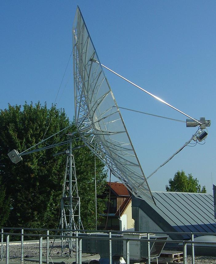
6 0 deg elevation and 40 deg elevation
7 easy access to the feed..

8 .and also a platform for some cool drink

9 Sun noise measurement by drift scan on 23cm (SFI=107)


10 Measurement of low level broadband noise is better with large bandwidth Moon noise on 1296 MHz 2,5kHz bandwidth 2 MHz bandwidth

11 Hardware and Software: Hardware: Preamp, INTERDIGITAL FILTER, RTL-SDR (Airspy SDR), PC Software for planning observations: Murmur by I0NAA Software for analyzation and display: IW5BHY and Presto

12 List of received pulsars (April 4th 2017) S/N values by IW5BHY software note * : The Crab pulsar was a challenge, 30 rotations/sec and high dispersion. note ** : The B and the B are only about 1deg apart from each other. 424 MHz profiles for both pulsars were obtained by analyzing the same recorded file. The two weakest pulsars detected are: 424 MHz: B (S400 = 57 mjy) 1294 MHz: B (S1400 = 10 mjy)

13 Pulsar B Frequency 1,39 Hz 714 ms period 3 pulses 424 MHz pre- and postpulse in normal mode 1294 MHz

14 The upper graph shows the dispersion at 424 MHz 2 MHz bandwidth: 4 channels 500kHz each

15 Verification Tests Pulse Period Check Dispersion Measure Check

16 QSB by scintillation on 23cm

17 During signal peaks it is possible to receive single pulses 70cm 23cm

18 This 3D plot displays 50 consecutive periods at a peak of positive scintillation. It is from one piece of observation of 36 seconds containing many single pulses. Andrea, IW5BHY, has found 50 single pulses in a one hour recording I made on 424 MHz. With a special written program he put the single pulses in a row, and generated an audio file from that. So you can even listen to the sound of the pulsar B :
. This is nearly as much as the pulse width itself.")
19 Pulsar B , high dispersion The channels are separated by slightly more than 8ms to each other on 424MHz (left). This is nearly as much as the pulse width itself. The dispersion is even visible on 1294 MHz (right)

20 Pulsar B , 6 hours observation frequency change by Doppler (1294 MHz)

21 Pulsar B double pulse (424 MHz) measured pulse profile confirmed by EPN profile catalogue
22 Crab-pulsar B Young pulsar, exists since a supernova explosion in 1054 (observed on earth as a star even visible at daylight for about two years) Rotates 30 times per second, fast speed slowdown Highly dispersed ( 3 ms per channel is the same as the pulse width) Nevertheless, the pulsar reception was positive even on the very first attempt! The observation time was 2 hours.

23 Crab pulsar ( 424 MHz) analyzed with IW5BHY software and Presto


24 Reception of B on 23cm with my 3m dish (10,5dB sun SFI=74)
 --------- Comparison using 10 MHz and 2 MHz")
25 Reception of B on 70cm by IW5BHY with corner reflector antenna (18dBi) Comparison using 10 MHz and 2 MHz bandwidth
26 Planning observations Finding candidates using ATNF pulsar catalogue S400 and S1400 values might be not correct, confirmation by other sources recommended Check pulse shape by EPN pulsar profile catalogue Pulse shape depends on frequency, W50 can be calculated for the planned observation band Check results obtained by other stations (Astropeiler 25m dish) Own chances can be stimated looking at the S/N ratio (example: B S1400=10mJy) Use Murmur (=Pulsar Planner) to see possible observation times RFI might depend on direction, time of the day. Also nighttime hours can cause less sleep ;-) Do not give up when an observation was negative!! On one occasion I needed up to 10 observations, 5 hours each, before I had a positive result

27 thank you for your attention
Pulsars detection for amateurs
 Pulsars detection for amateurs Mario Armando Natali, I0NAA December 10, 2017 1 Introduction The pulsars, whose name is originated from the contraction of the two words Pulsating Star, are a special class
Pulsars How To Detect
 Pulsars How To Detect In the following article I will describe how you can detect pulsars, at least the strongest, using amateur radio EME equipment. The first question is what hardware and band to use:
Detection of 21cm Jean-Jacques MAINTOUX - F1EHN
 Detection of Pulsars @ 21cm Jean-Jacques MAINTOUX - F1EHN Pulsar : Pulsating star Table of Contents 1 Signal Research and Choice of Techniques :... 2 1.1 Evaluation : First Reception Test... 2 1.2 Effect
Session Three: Pulsar Data and Dispersion Measure
 Slide 1 Session Three: Pulsar Data and Dispersion Measure Sue Ann Heatherly and Sarah Scoles Slide 2 Plot Review Average pulse profile Time domain Reduced χ 2 Recall that last week, we learned about three
Autonomous spacecraft navigation using millisecond pulsars. Vincent Trung Michael Hecht Vincent Fish
 Autonomous spacecraft navigation using millisecond pulsars Vincent Trung Michael Hecht Vincent Fish Overview 1. Project description 2. Data collection 3. Methods 4. What does it tell us? 5. Results 6.
EME ON 77.5 Ghz. Sergei RW3BP, EME Meeting in Orebro, Sweden, May First of all few words about difficulties we have for EME on this band.
 EME ON 77.5 Ghz Sergei RW3BP, EME Meeting in Orebro, Sweden, May 2013. First of all few words about difficulties we have for EME on this band. You can see formula for signal to noise ratio. It is based
Introduction to Radio Astronomy
 Introduction to Radio Astronomy The Visible Sky, Sagittarius Region 2 The Radio Sky 3 4 Optical and Radio can be done from the ground! 5 Outline The Discovery of Radio Waves Maxwell, Hertz and Marconi
The VK3UM Radiation and System Performance Calculator
 The VK3UM Radiation and System Performance Calculator 1. Disclaimer... 2 2. Background... 2 3. Calculations... 2 4. Features... 2 5. Default Parameters... 3 6. Parameter Description... 4 7. On Axis Exclusion
HOW CAN WE DISTINGUISH TRANSIENT PULSARS FROM SETI BEACONS?
 HOW CAN WE DISTINGUISH TRANSIENT PULSARS FROM SETI BEACONS? James Benford and Dominic Benford Microwave Sciences Lafayette, CA How would observers differentiate SETI beacons from pulsars or other exotic
Prelab Questions Read the section of your lab titled Background: Neutron Stars and Pulsars and answer the following questions.
 Lab 10: CLEA Radio Astronomy of Pulsars Prelab Questions Read the section of your lab titled Background: Neutron Stars and Pulsars and answer the following questions. 1. Why are neutron stars so difficult
I( ) 1 P a g e. Estimation of modulation index of pulsar
 1 P a g e. Estimation of modulation index of pulsar") 1. Aim of the experiment The aim of this experiment is to find out the pulse to pulse intensity modulation of the pulsar radio emission. ORT will be used to carry out observations of a select list of pulsars
1. Aim of the experiment The aim of this experiment is to find out the pulse to pulse intensity modulation of the pulsar radio emission. ORT will be used to carry out observations of a select list of pulsars
Radio Astronomy for Amateurs. Presented by Keith Payea AG6CI
 Radio Astronomy for Amateurs Presented by Keith Payea AG6CI Outline Radio Astronomy Basics: What, How, Why How Amateurs can participate and contribute What is Radio Astronomy? The Study of the non-visible
APPENDIX A TEST PLOTS. (Model: 15Z970)
") APPENDIX A APPENDIX A TEST PLOTS (Model: 15Z970) APPENDIX A-Page 1 of 36 TABLE OF CONTENTS A.1 6dB BANDWIDTH MEASUREMENT... 2 A.1.1 6dB Bandwidth Result... 2 A.1.2 Measurement Plots... 3 A.2 MAXIMUM PEAK
APPENDIX A APPENDIX A TEST PLOTS (Model: 15Z970) APPENDIX A-Page 1 of 36 TABLE OF CONTENTS A.1 6dB BANDWIDTH MEASUREMENT... 2 A.1.1 6dB Bandwidth Result... 2 A.1.2 Measurement Plots... 3 A.2 MAXIMUM PEAK
Space Frequency Coordination Group
 Space Frequency Coordination Group Report SFCG 38-1 POTENTIAL RFI TO EESS (ACTIVE) CLOUD PROFILE RADARS IN 94.0-94.1 GHZ FREQUENCY BAND FROM OTHER SERVICES Abstract This new SFCG report analyzes potential
RECOMMENDATION ITU-R SA (Question ITU-R 210/7)
") Rec. ITU-R SA.1016 1 RECOMMENDATION ITU-R SA.1016 SHARING CONSIDERATIONS RELATING TO DEEP-SPACE RESEARCH (Question ITU-R 210/7) Rec. ITU-R SA.1016 (1994) The ITU Radiocommunication Assembly, considering
Rec. ITU-R SA.1016 1 RECOMMENDATION ITU-R SA.1016 SHARING CONSIDERATIONS RELATING TO DEEP-SPACE RESEARCH (Question ITU-R 210/7) Rec. ITU-R SA.1016 (1994) The ITU Radiocommunication Assembly, considering
Amateur Pulsar Detection. Using the RTL2832U DVB-T. and a 3m Dish
 Amateur Pulsar Detection Using the RTL2832U DVB-T and a 3m Dish Peter East, with assistance from Guillermo Gancio, Michiel Klaassen and Steve Olney Introduction Background Why RTL SDR? RTL Radio Telescope
The VK3UM Radiation and System Performance Calculator
 The VK3UM Radiation and System Performance Calculator 1. Disclaimer... 3 2. Background... 3 3. Program Aim... 3 4. Screen Options... 4 5. Features... 5 6. Default Parameters... 6 7. Parameter Descriptions...
255 km Aircraft Scatter QSO on 24 GHz
 255 km Aircraft Scatter QSO on 24 GHz First crossing of Bass Strait on 24 GHz By Rex Moncur VK7MO and David Smith VK3HZ On 13 March 2012, VK3HZ at Mt Liptrap near Wilson s Promontory in Victoria worked
4GHz / 6GHz Radiation Measurement System
 4GHz / 6GHz Radiation Measurement System The MegiQ Radiation Measurement System (RMS) is a compact test system that performs 3-axis radiation pattern measurement in non-anechoic spaces. With a frequency
To print higher-resolution math symbols, click the Hi-Res Fonts for Printing button on the jsmath control panel.
 To print higher-resolution math symbols, click the Hi-Res Fonts for Printing button on the jsmath control panel. Radiometers Natural radio emission from the cosmic microwave background, discrete astronomical
RECOMMENDATION ITU-R F *
 Rec. ITU-R F.699-6 1 RECOMMENATION ITU-R F.699-6 * Reference radiation patterns for fixed wireless system antennas for use in coordination studies and interference assessment in the frequency range from
Aircraft Scatter on 10 and 24 GHz using JT65c and ISCAT-A
 Aircraft Scatter on 10 and 24 GHz using JT65c and ISCAT-A By VK7MO and David Smith VK3HZ The authors have been using the digital modes JT65C and ISCAT-A to work aircraft scatter at distances of up to 842
Bike Generator Project
 Bike Generator Project Each lab section will build 1 bike generator Each lab group will build 1 energy board Connect and test energy board and bike generator Create curriculum materials and demos to teach
AGF-216. The Earth s Ionosphere & Radars on Svalbard
 AGF-216 The Earth s Ionosphere & Radars on Svalbard Katie Herlingshaw 07/02/2018 1 Overview Radar basics what, how, where, why? How do we use radars on Svalbard? What is EISCAT and what does it measure?
Aircraft Scatter Propagation on 10 GHz using JT65C
 Aircraft Scatter Propagation on 10 GHz using JT65C Results of initial Tests over a 624 km Path By Rex Moncur VK7MO and David Smith VK3HZ This is an initial report of our first tests of 10 GHz propagation
The Excitement & Challenges of 24 GHz EME. By Al Ward W5LUA August 17, 2012
 The Excitement & Challenges of 24 GHz EME By Al Ward W5LUA August 17, 2012 Introduction History Early Activity Present Activity Equipment Challenges Summary The First 24 GHz EME QSO The First 24 GHz EME
Characteristics of HF Coastal Radars
 Function Characteristics System 1 Maximum operational (measurement) range** Characteristics of HF Coastal Radars 5 MHz Long-range oceanographic 160-220 km average during (daytime)* System 2 System 3 System
Radio observation of SMART-1 in its last perilune orbit
 Research Collection Report Radio observation of SMART-1 in its last perilune orbit Author(s): Monstein, Christian A. Publication Date: 2006 Permanent Link: https://doi.org/10.3929/ethz-a-005238194 Rights
Polarization. Contents. Polarization. Types of Polarization
 Contents By Kamran Ahmed Lecture # 7 Antenna polarization of satellite signals Cross polarization discrimination Ionospheric depolarization, rain & ice depolarization The polarization of an electromagnetic
RECOMMENDATION ITU-R SA Protection criteria for deep-space research
 Rec. ITU-R SA.1157-1 1 RECOMMENDATION ITU-R SA.1157-1 Protection criteria for deep-space research (1995-2006) Scope This Recommendation specifies the protection criteria needed to success fully control,
Electromagnetic (Light) Waves Electromagnetic Waves
 Waves Electromagnetic Waves") Physics R Date: Review Questions 1. An ocean wave traveling at 3 m/s has a wavelength of 1.6 meters. a. What is the frequency of the wave? b. What is the period of the wave? Electromagnetic (Light) Waves
Physics R Date: Review Questions 1. An ocean wave traveling at 3 m/s has a wavelength of 1.6 meters. a. What is the frequency of the wave? b. What is the period of the wave? Electromagnetic (Light) Waves
KULLIYYAH OF ENGINEERING
 KULLIYYAH OF ENGINEERING DEPARTMENT OF ELECTRICAL & COMPUTER ENGINEERING ANTENNA AND WAVE PROPAGATION LABORATORY (ECE 4103) EXPERIMENT NO 3 RADIATION PATTERN AND GAIN CHARACTERISTICS OF THE DISH (PARABOLIC)
Chapter 22. Electromagnetic Waves
 Ch-22-1 Chapter 22 Electromagnetic Waves Questions 1. The electric field in an EM wave traveling north oscillates in an east-west plane. Describe the direction of the magnetic field vector in this wave.
ARTICLE 22. Space services 1
 CHAPTER VI Provisions for services and stations RR22-1 ARTICLE 22 Space services 1 Section I Cessation of emissions 22.1 1 Space stations shall be fitted with devices to ensure immediate cessation of their
NanoCom ANT430. Datasheet 70 cm band Omnidirectional UHF CubeSat antenna
 NanoCom ANT430 Datasheet 70 cm band Omnidirectional UHF CubeSat antenna 1 Table of Contents 1 TABLE OF CONTENTS... 2 2 OVERVIEW... 3 2.1 HIGHLIGHTED FEATURES... 3 2.2 FUNCTIONAL DESCRIPTION... 3 2.2.1
CHAPTER 8 ANTENNAS 1
 CHAPTER 8 ANTENNAS 1 2 Antennas A good antenna works A bad antenna is a waste of time & money Antenna systems can be very inexpensive and simple They can also be very expensive 3 Antenna Considerations
What are the keys to better weak signal receive performance?
 1 Determinants of receiver sensitivity What are the keys to better weak signal receive performance? One of the greatest advances we have seen in the last few years has been the application of Digital Signal
Ascent Ground and Satellite Demonstration
 Ascent Ground and Satellite Demonstration By Ray Roberge, WA1CYB & Howie DeFelice, AB2S WA1CYB s1 Big Picture Goals Place more capable satellites into higher orbits Utilize software defined radios A programmable
77 GHz EME at WA3ZKR/4 at Morehead State University
 77 GHz EME at WA3ZKR/4 at Morehead State University Al Ward W5LUA October 19, 2013 WWW..ORG 1 Introduction After some discussion with Jeff at MUD and subsequent approval by the folks at Morehead State
Relative Navigation, Timing & Data. Communications for CubeSat Clusters. Nestor Voronka, Tyrel Newton
 Relative Navigation, Timing & Data Communications for CubeSat Clusters Nestor Voronka, Tyrel Newton Tethers Unlimited, Inc. 11711 N. Creek Pkwy S., Suite D113 Bothell, WA 98011 425-486-0100x678 voronka@tethers.com
3 D Corner Reflector Antenna as an efficient feed for offset parabolic antennas for 5.8 GHz Dragoslav Dobričić, YU1AW
 3 D Corner Reflector Antenna as an efficient feed for offset parabolic antennas for 5.8 GHz Dragoslav Dobričić, YU1AW Abstract I n this article I present a modification of 3D corner reflector antenna in
Introduction to Radio Astronomy!
 Introduction to Radio Astronomy! Sources of radio emission! Radio telescopes - collecting the radiation! Processing the radio signal! Radio telescope characteristics! Observing radio sources Sources of
THE KAROO ARRAY TELESCOPE (KAT) & FPA EFFORT IN SOUTH AFRICA
 & FPA EFFORT IN SOUTH AFRICA") THE KAROO ARRAY TELESCOPE (KAT) & FPA EFFORT IN SOUTH AFRICA Dr. Dirk Baker (KAT FPA Sub-system Manager) Prof. Justin Jonas (SKA SA Project Scientist) Ms. Anita Loots (KAT Project Manager) Mr. David de
THE KAROO ARRAY TELESCOPE (KAT) & FPA EFFORT IN SOUTH AFRICA Dr. Dirk Baker (KAT FPA Sub-system Manager) Prof. Justin Jonas (SKA SA Project Scientist) Ms. Anita Loots (KAT Project Manager) Mr. David de
Phased Array Feeds & Primary Beams
 Phased Array Feeds & Primary Beams Aidan Hotan ASKAP Deputy Project Scientist 3 rd October 2014 CSIRO ASTRONOMY AND SPACE SCIENCE Outline Review of parabolic (dish) antennas. Focal plane response to a
VK7MO 10 GHz EME Grid Square Tour across Australia
 VK7MO 10 GHz EME Grid Square Tour across Australia From mid November to mid December VK7MO took his portable 10 GHz system (Fig 1 and Fig 2) across Australia and activated some 25 grid squares (Fig 3)
GSP303D 3-Axis Digital Magnetic Field Transmitter
 Digital Handheld Magnetic Transmitter Transmitter Field Transmitter GSP303D 3-Axis Digital Magnetic Field Transmitter Digital Output (RS485) Accuracy Based on Reading (Not Range) Wide Supply Power: 5 to
ADVANCED SATELLITE COMMUNICATION (ASC) CASE STUDY DESIGN OF SYSTEM LEVEL CONCEPT FOR A SATELLITE LINK. 29 February 2016
 CASE STUDY DESIGN OF SYSTEM LEVEL CONCEPT FOR A SATELLITE LINK. 29 February 2016") HOCHSCHULE BREMEN UNIVERSITY OF APPLIED SCIENCES FACULTY OF ENGINEERING AND COMPUTER SCIENCE ADVANCED SATELLITE COMMUNICATION (ASC) CASE STUDY DESIGN OF SYSTEM LEVEL CONCEPT FOR A SATELLITE LINK 29 February
HOCHSCHULE BREMEN UNIVERSITY OF APPLIED SCIENCES FACULTY OF ENGINEERING AND COMPUTER SCIENCE ADVANCED SATELLITE COMMUNICATION (ASC) CASE STUDY DESIGN OF SYSTEM LEVEL CONCEPT FOR A SATELLITE LINK 29 February
Pulsar polarimetry. with. Charlotte Sobey. Dr. Aris Noutsos & Prof. Michael Kramer
 Pulsar polarimetry with Dr. Aris Noutsos & Prof. Michael Kramer Outline Introduction Observations Ionosphere Outline Pulsars as objects Pulsars as probes of the ISM Faraday rotation using RM synthesis
Engineering Discovery
 Modeling, Computing, & Measurement: Measurement Systems # 4 Dr. Kevin Craig Professor of Mechanical Engineering Rensselaer Polytechnic Institute 1 Frequency Response and Filters When you hear music and
Technician Licensing Class
 Technician Licensing Class Talk to Outer Presented Space by Amateur Radio Technician Class Element 2 Course Presentation ELEMENT 2 SUB-ELEMENTS (Groupings) About Ham Radio Call Signs Control Mind the Rules
Introduction to Radar Systems. Radar Antennas. MIT Lincoln Laboratory. Radar Antennas - 1 PRH 6/18/02
 Introduction to Radar Systems Radar Antennas Radar Antennas - 1 Disclaimer of Endorsement and Liability The video courseware and accompanying viewgraphs presented on this server were prepared as an account
Some Ideas for Medium Wave DXing
 Some Ideas for Medium Wave DXing This season, Christoph Ratzer, OE2CRM, triggered a deeper interest in medium wave reception at me; thanks! It also led to discover some aspects of Simon Brown s, G4ELI,
ATCA Antenna Beam Patterns and Aperture Illumination
 1 AT 39.3/116 ATCA Antenna Beam Patterns and Aperture Illumination Jared Cole and Ravi Subrahmanyan July 2002 Detailed here is a method and results from measurements of the beam characteristics of the
ANT6: The Half-Wave Dipole Antenna
 In this lecture, we simplify the space radiating current analysis to include the special (but very important) case of the general wire antenna. Concentrating on results for the half-wave dipole, we demonstrate
RADIATION PATTERNS. The half-power (-3 db) beamwidth is a measure of the directivity of the antenna.
 beamwidth is a measure of the directivity of the antenna.") RADIATION PATTERNS The radiation pattern is a graphical depiction of the relative field strength transmitted from or received by the antenna. Antenna radiation patterns are taken at one frequency, one
RADIATION PATTERNS The radiation pattern is a graphical depiction of the relative field strength transmitted from or received by the antenna. Antenna radiation patterns are taken at one frequency, one
Spectral Line Imaging
 ATNF Synthesis School 2003 Spectral Line Imaging Juergen Ott (ATNF) Juergen.Ott@csiro.au Topics Introduction to Spectral Lines Velocity Reference Frames Bandpass Calibration Continuum Subtraction Gibbs
Dense Aperture Array for SKA
 Dense Aperture Array for SKA Steve Torchinsky EMBRACE Why a Square Kilometre? Detection of HI in emission at cosmological distances R. Ekers, SKA Memo #4, 2001 P. Wilkinson, 1991 J. Heidmann, 1966! SKA
Radio Astronomy of Pulsars
 Radio Astronomy of Pulsars Student Manual A Manual to Accompany Software for the Inductory Astronomy Lab Exercise Document SMG 8: Version 1 Department of Physics Gettysburg College Gettysburg, PA 1735
Class Overview. Antenna Fundamentals Repeaters Duplex and Simplex Nets and Frequencies Cool Radio Functions Review
 Class Overview Antenna Fundamentals Repeaters Duplex and Simplex Nets and Frequencies Cool Radio Functions Review Antennas Antennas An antenna is a device used for converting electrical currents into electromagnetic
Exercise 4. Angle Tracking Techniques EXERCISE OBJECTIVE
 Exercise 4 Angle Tracking Techniques EXERCISE OBJECTIVE When you have completed this exercise, you will be familiar with the principles of the following angle tracking techniques: lobe switching, conical
Signal Flow & Radiometer Equation. Aletha de Witt AVN-Newton Fund/DARA 2018 Observational & Technical Training HartRAO
 Signal Flow & Radiometer Equation Aletha de Witt AVN-Newton Fund/DARA 2018 Observational & Technical Training HartRAO Understanding Radio Waves The meaning of radio waves How radio waves are created -
Ch. III - Limits of single polarity antennas in the VHF and UHF bands
 Ch. III - Limits of single polarity antennas in the VHF and UHF bands Ch. I 2014 QSB origins 2 m Faraday Ch. II 2016 Extension of Excel sheet to VHF and UHF bands From studies by Giorgio Marchi, IK1UWL
RADIOMETRIC TRACKING. Space Navigation
 RADIOMETRIC TRACKING Space Navigation Space Navigation Elements SC orbit determination Knowledge and prediction of SC position & velocity SC flight path control Firing the attitude control thrusters to
A CubeSat Radio Beacon Experiment
 A CubeSat Radio Beacon Experiment CUBEACON A Beacon Test of Designs for the Future Antenna? Michael Cousins SRI International Multifrequency? Size, Weight and Power? CubeSat Developers Workshop, April
16 - INTERSTELLAR COMUNICATION
 NSCI 314 LIFE IN THE COSMOS 16 - INTERSTELLAR COMUNICATION Dr. Karen Kolehmainen Department of Physics, CSUSB http://physics.csusb.edu/~karen/ HOW TO SEARCH FOR LIFE IN OTHER SOLAR SYSTEMS: TRAVEL OR COMMUNICATION?
Allen Telescope Array & Radio Frequency Interference. Geoffrey C. Bower UC Berkeley
 Allen Telescope Array & Radio Frequency Interference Geoffrey C. Bower UC Berkeley Allen Telescope Array Large N design 350 x 6.1m antennas Sensitivity of the VLA Unprecedented imaging capabilities Continuous
ATS 351 Lecture 9 Radar
 ATS 351 Lecture 9 Radar Radio Waves Electromagnetic Waves Consist of an electric field and a magnetic field Polarization: describes the orientation of the electric field. 1 Remote Sensing Passive vs Active
Traveling Wave Antennas
 Traveling Wave Antennas Antennas with open-ended wires where the current must go to zero (dipoles, monopoles, etc.) can be characterized as standing wave antennas or resonant antennas. The current on these
LWA Equipment RF Emissions: Spectrum Analyzers and Laptops
 LWA Equipment RF Emissions: Spectrum Analyzers and Laptops Ylva Pihlström, UNM 8/27/06 Summary I report on measurements in the VLA shielded chamber of the radio frequency emission levels of spectrum analyzers
Space multi-beam antenna with very high figure of merit, for Ka-band multimedia via satellite transmission
 Space multi-beam antenna with very high figure of merit, for Ka-band multimedia via satellite transmission Yann CAILLOCE, Gerard CAILLE: Alcatel Space Industries, B.P. 87, 3037 Toulouse Cedex, France.
VK3UM Impedance Calculator. Table of Contents
 Table of Contents Concentric Tube Ratio 3 Centered Strip Line 5 Quarter Wave transition. 6 Coaxial Lengths 7 VSWR Calculator. 8 Dish Reflection Coefficient 10 Convert Fractions to a decimal value. 12 Author
Introduction to Radio Astronomy. Richard Porcas Max-Planck-Institut fuer Radioastronomie, Bonn
 Introduction to Radio Astronomy Richard Porcas Max-Planck-Institut fuer Radioastronomie, Bonn 1 Contents Radio Waves Radio Emission Processes Radio Noise Radio source names and catalogues Radio telescopes
- Setup and Operation
 - What is JT-65-65 tones sent in 200 HZ bandwidth - Developed for EME - Setup and Operation - Soundcard interface - WSJT-X software (free) - On-Air Demo - PC, Soundcard & Rig Ed Erny - NZ1Q St Petersburg
4/29/2012. General Class Element 3 Course Presentation. Radio Wave Propagation. Radio Wave Propagation. Radio Wave Propagation.
 General Class Element 3 Course Presentation ti ELEMENT 3 SUB ELEMENTS General Licensing Class Subelement G3 3 Exam Questions, 3 Groups G1 Commission s Rules G2 Operating Procedures G3 G4 Amateur Radio
Exercise 1-4. The Radar Equation EXERCISE OBJECTIVE DISCUSSION OUTLINE DISCUSSION OF FUNDAMENTALS
 Exercise 1-4 The Radar Equation EXERCISE OBJECTIVE When you have completed this exercise, you will be familiar with the different parameters in the radar equation, and with the interaction between these
Vela Pulsar Project Early Results
 Vela Pulsar Project Early Results Steve Olney (VK2XV) NRARAO 13th April 2015 Some encouraging results are described and possible future developments Introduction main GUI overview. As you can see there
Simulating a PTA with metronomes and microphones: A user s guide for a double-metronome timing & correlation demonstration
 Simulating a PTA with metronomes and microphones: A user s guide for a double-metronome timing & correlation demonstration October 21, 2015 Page 1 Contents I Purpose....................................................
Scalable Front-End Digital Signal Processing for a Phased Array Radar Demonstrator. International Radar Symposium 2012 Warsaw, 24 May 2012
 Scalable Front-End Digital Signal Processing for a Phased Array Radar Demonstrator F. Winterstein, G. Sessler, M. Montagna, M. Mendijur, G. Dauron, PM. Besso International Radar Symposium 2012 Warsaw,
LnR Precision, Inc. 107 East Central Avenue, Asheboro, NC
 LD5 CW/SSB QRP Transceiver Quick guide manual Description: At the development base of the digital signal processing unit, an algorithm is embedded for IQ processing of the channels with phase suppression
ATA s Nanoradian-Class Rotational Sensors. 10 November 2009
 ATA s Nanoradian-Class Rotational Sensors 10 November 2009 ATA Overview Founded 1975 A-TECH Corporation, d.b.a. Applied Technology Associates Customers Include USAF, Sandia NL, US Army, MDA, NASA, US Navy,
Development of a noval Switched Beam Antenna for Communications
 Master Thesis Presentation Development of a noval Switched Beam Antenna for Communications By Ashraf Abuelhaija Supervised by Prof. Dr.-Ing. Klaus Solbach Institute of Microwave and RF Technology Department
RECOMMENDATION ITU-R S.733-1* (Question ITU-R 42/4 (1990))**
)**") Rec. ITU-R S.733-1 1 RECOMMENDATION ITU-R S.733-1* DETERMINATION OF THE G/T RATIO FOR EARTH STATIONS OPERATING IN THE FIXED-SATELLITE SERVICE (Question ITU-R 42/4 (1990))** Rec. ITU-R S.733-1 (1992-1993)
Rec. ITU-R S.733-1 1 RECOMMENDATION ITU-R S.733-1* DETERMINATION OF THE G/T RATIO FOR EARTH STATIONS OPERATING IN THE FIXED-SATELLITE SERVICE (Question ITU-R 42/4 (1990))** Rec. ITU-R S.733-1 (1992-1993)
Wide-Band Imaging. Outline : CASS Radio Astronomy School Sept 2012 Narrabri, NSW, Australia. - What is wideband imaging?
 Wide-Band Imaging 24-28 Sept 2012 Narrabri, NSW, Australia Outline : - What is wideband imaging? - Two Algorithms Urvashi Rau - Many Examples National Radio Astronomy Observatory Socorro, NM, USA 1/32
Exercise 1-3. Radar Antennas EXERCISE OBJECTIVE DISCUSSION OUTLINE DISCUSSION OF FUNDAMENTALS. Antenna types
 Exercise 1-3 Radar Antennas EXERCISE OBJECTIVE When you have completed this exercise, you will be familiar with the role of the antenna in a radar system. You will also be familiar with the intrinsic characteristics
BHARATHIDASAN ENGINEERING COLLEGE NATTARAMPALLI Frequently Asked Questions (FAQ) Unit 1
 Unit 1") BHARATHIDASAN ENGINEERING COLLEGE NATTARAMPALLI 635854 Frequently Asked Questions (FAQ) Unit 1 Degree / Branch : B.E / ECE Sem / Year : 3 rd / 6 th Sub Name : Antennas & Wave Propagation Sub Code : EC6602
BHARATHIDASAN ENGINEERING COLLEGE NATTARAMPALLI 635854 Frequently Asked Questions (FAQ) Unit 1 Degree / Branch : B.E / ECE Sem / Year : 3 rd / 6 th Sub Name : Antennas & Wave Propagation Sub Code : EC6602
UNIVERSITI MALAYSIA PERLIS
 UNIVERSITI MALAYSIA PERLIS SCHOOL OF COMPUTER & COMMUNICATIONS ENGINEERING EKT 341 LABORATORY MODULE LAB 2 Antenna Characteristic 1 Measurement of Radiation Pattern, Gain, VSWR, input impedance and reflection
(3) A traveling wave transfers, but it does not transfer.
 A traveling wave transfers, but it does not transfer.") AP PHYSICS TEST 9 Waves and Sound (1) Give a good physics definition of a wave. (2) Any wave has as its source. (3) A traveling wave transfers, but it does not transfer. (4) What is a mechanical wave?
AP PHYSICS TEST 9 Waves and Sound (1) Give a good physics definition of a wave. (2) Any wave has as its source. (3) A traveling wave transfers, but it does not transfer. (4) What is a mechanical wave?
LE/ESSE Payload Design
 LE/ESSE4360 - Payload Design 4.3 Communications Satellite Payload - Hardware Elements Earth, Moon, Mars, and Beyond Dr. Jinjun Shan, Professor of Space Engineering Department of Earth and Space Science
Waves Q1. MockTime.com. (c) speed of propagation = 5 (d) period π/15 Ans: (c)
 speed of propagation = 5 (d) period π/15 Ans: (c)") Waves Q1. (a) v = 5 cm (b) λ = 18 cm (c) a = 0.04 cm (d) f = 50 Hz Q2. The velocity of sound in any gas depends upon [1988] (a) wavelength of sound only (b) density and elasticity of gas (c) intensity
Waves Q1. (a) v = 5 cm (b) λ = 18 cm (c) a = 0.04 cm (d) f = 50 Hz Q2. The velocity of sound in any gas depends upon [1988] (a) wavelength of sound only (b) density and elasticity of gas (c) intensity
# -antenna (hash) 4 direction switchable array
 4 direction switchable array") # -antenna (hash) 4 direction switchable array Feasibility study Paper on CCF & OHDXF cruise 4.1.2012 Pekka Ketonen 4.2.2012 OH1TV 1 4 direction, instant switching 4.2.2012 OH1TV 2 Features Instant direction
# -antenna (hash) 4 direction switchable array Feasibility study Paper on CCF & OHDXF cruise 4.1.2012 Pekka Ketonen 4.2.2012 OH1TV 1 4 direction, instant switching 4.2.2012 OH1TV 2 Features Instant direction
RADIOMETRIC TRACKING. Space Navigation
 RADIOMETRIC TRACKING Space Navigation October 24, 2016 D. Kanipe Space Navigation Elements SC orbit determination Knowledge and prediction of SC position & velocity SC flight path control Firing the attitude
HEMERA Constellation of passive SAR-based micro-satellites for a Master/Slave configuration
 HEMERA Constellation of passive SAR-based micro-satellites for a Master/Slave HEMERA Team Members: Andrea Bellome, Giulia Broggi, Luca Collettini, Davide Di Ienno, Edoardo Fornari, Leandro Lucchese, Andrea
Loop and Slot Antennas
 Loop and Slot Antennas Prof. Girish Kumar Electrical Engineering Department, IIT Bombay gkumar@ee.iitb.ac.in (022) 2576 7436 Loop Antenna Loop antennas can have circular, rectangular, triangular or any
Resonant Antennas: Wires and Patches
 Resonant Antennas: Wires and Patches Dipole Antennas Antenna 48 Current distribution approximation Un-normalized pattern: and Antenna 49 Radiating power: For half-wave dipole and,, or at exact resonance.
LWA Users Meeting Pulsars II: Software and Survey Kevin Stovall
 LWA Users Meeting 2012 Pulsars II: Software and Survey Kevin Stovall Pulsar Software - PRESTO - PSRCHIVE - TEMPO/TEMPO2 - writepsrfits.py - Coherent Dedispersion Status Pulsar/Transient Survey - All Sky
REPORT ITU-R BT Radiation pattern characteristics of UHF * television receiving antennas
 Rep. ITU-R BT.2138 1 REPORT ITU-R BT.2138 Radiation pattern characteristics of UHF * television receiving antennas (2008) 1 Introduction This Report describes measurements of the radiation pattern characteristics
UNDERSTANDING DOPPLER SHIFT: CRITICAL KNOWLEDGE FOR SUCCESSFUL EME ON THE HIGHER BANDS by Al Katz K2UYH
 UNDERSTANDING DOPPLER SHIFT: CRITICAL KNOWLEDGE FOR SUCCESSFUL EME ON THE HIGHER BANDS by Al Katz K2UYH Abstract: This paper discusses the shift in signal frequency caused by the Doppler
RTCA Special Committee 186, Working Group 5 ADS-B UAT MOPS. Meeting #3. UAT Performance in the Presence of DME Interference
 UAT-WP-3-2 2 April 21 RTCA Special Committee 186, Working Group 5 ADS-B UAT MOPS Meeting #3 UAT Performance in the Presence of DME Interference Prepared by Warren J. Wilson and Myron Leiter The MITRE Corp.
RESIT EXAM: WAVES and ELECTROMAGNETISM (AE1240-II) 10 August 2015, 14:00 17:00 9 pages
 10 August 2015, 14:00 17:00 9 pages") Faculty of Aerospace Engineering RESIT EXAM: WAVES and ELECTROMAGNETISM (AE140-II) 10 August 015, 14:00 17:00 9 pages Please read these instructions first: 1) This exam contains 5 four-choice questions.
Faculty of Aerospace Engineering RESIT EXAM: WAVES and ELECTROMAGNETISM (AE140-II) 10 August 015, 14:00 17:00 9 pages Please read these instructions first: 1) This exam contains 5 four-choice questions.
MEASURING ELECTROMAGNETIC EMISSIONS FROM LARGE POWER ROTATING MACHINES
 Vienna, AUSTRIA,, September 25-28 MEASURING ELECTROMAGNETIC EMISSIONS FROM LARGE POWER ROTATING MACHINES P. Ferrari, A. Mariscotti and P. Pozzobon Electrical Engineering Department University of Genova