REPORT ITU-R BT Radiation pattern characteristics of UHF * television receiving antennas
|
|
|
- Quentin Burns
- 6 years ago
- Views:
Transcription
1 Rep. ITU-R BT REPORT ITU-R BT.2138 Radiation pattern characteristics of UHF * television receiving antennas (2008) 1 Introduction This Report describes measurements of the radiation pattern characteristics of UHF television receiving antennas. The measurements were made to determine the performance of twelve UHF antennas used for TV reception. Though all antennas tested were designed for multiband operation, the antennas tested covered, inter alia, the frequency range of TV channels 40 to 60 for 8 MHz channel plans and TV channels 41 to 65 for 7 MHz plans. These frequency ranges are extensively used for terrestrial television broadcasting services by most ITU administrations. 2 Background Many administrations currently operate digital and/or analogue broadcasting services in the UHF band. Recommendation ITU-R BT contains a mask for receiving antenna directivity to be used in the planning of terrestrial television services. This does not constitute a design specification for receiving antennas, but is an assumption about their directivity which affects the calculation of potential interference from other services into the broadcasting service. As part of its work in the study period in ITU-R, Australia provided representative data for the off-axis performance of UHF receiving antennas (in the elevation plane), noting that the performance may vary with the polarization of the receiving antenna. The results are in Annex 1. Within this study it is clear that a number of antennas fit well within the Recommendation ITU-R BT.419 mask, while others do not due to their broader patterns and lower gain. This is particularly evident at the lower frequencies. 3 Factors for consideration 3.1 Existing antenna population Statistics from antenna manufacturers indicate that the antenna types tested in this study represent a high percentage of antenna used in one administration. If these figures were extrapolated for a 10-year period (the estimated notional usable lifetime of a TV antenna) then, given the general commonality of TV antenna designs around the world, the characteristics found in Annex 1 may represent performance characteristics that are also valid for other administrations. * The terrestrial television broadcasting service is found in the UHF frequency range of 470 to 890 MHz (refer Article 5 of the Radio Regulations). Performance of the television receiving antennas in upper portion of the UHF band was the subject under study.
2 2 Rep. ITU-R BT Impulsive noise This Report states in Annex 1 that a certain AUT (antenna under test) was susceptible to noise generated by the measurement rotator during a swept frequency measurement using a broadband detector. Turning off the motor eliminated the noise so all further swept frequency measurements were conducted when the measurement rotator was turned off. Impulse noise immunity is an important consideration for receiver performance and reception signal quality for both analogue and particularly for digital television reception. Interference being received via the antenna may consume level and quality margins. Impulse noise rejection is, amongst other things, dependent upon correct cable terminations and matching cables to the antenna. Annex 1 1 Antennas measured The antennas measured are listed in Table 1: (1) (2) (3) Antenna number Antenna design TABLE 1 Antennas measured Antenna description Band Mounting location Feed connection 1 Yagi 9 elements IV/V Centre Saddle 2 Yagi 12 elements IV/V Centre F connector 3 Phased array 4 elements IV/V Rear Saddle 4 Phased array 4 elements IV/V Rear Saddle 5 Yagi 18 elements IV/V Rear F connector 6 Yagi 20 elements IV/V Centre F connector 7 Combination 8 Combination 9 Combination 10 Combination 11 Cross-polarized 12 Cross-polarized UHF 8 elements VHF 4 elements UHF 10 elements VHF 4 elements UHF 18 elements VHF 8 elements UHF 10 elements VHF 6 elements UHF 10 elements VHF 6 elements UHF 10 elements VHF 6 elements Tuneable UHF frequency range of MHz. Tuneable UHF frequency range of MHz. Tuneable UHF frequency range of MHz. I/II/III/IV/V Centre F connector IV/V (1) Centre F connector III/IV/V III/IV/V Centre Centre F connector F connector I/II/III/IV/V (2) Centre Saddle I/II/III/IV/V (3) Centre F connector
3 Rep. ITU-R BT Measurements undertaken For all antennas listed above the following system parameters were measured: 360 radiation patterns in the azimuth plane at two frequencies, 620 MHz and 790 MHz within the tunable UHF frequency range. Four radiation pattern cuts at ϕ = 0, 45, 90 and 135 were measured at each frequency. Gain-normalized 1 swept-frequency measurements over the range of 620 MHz to 790 MHz within the tunable UHF frequency range. 3 Measurement description The radiation patterns were measured on the CSIRO 40 metre outdoor antenna test range in Sydney, Australia, using an Agilent E4407B spectrum analyser as the receiver. The measurement system was set up with a standard gain horn (SGH) as the transmit horn allowing the gain of the antenna-under-test (AUT) to be calculated. A linear-polarized WR1150 rectangular pyramidal horn, with a nominal gain of 16.4 dbi, was used for the SGH. Two 6 m RG6 quad-shield 75 Ω cables were used to connect the AUTs to the measurement system. For the AUTs with an F-type balun input a cable with connectors at both ends was used. For the AUTs with saddle-type balun input a modified cable with one connector removed was used. These cables were then connected to a minimum loss pad used to match impedances between the 75 Ω AUT and the measurement 50 Ω system. The measurement procedure, listed below, was identical for each AUT at both measurement frequencies. Step 1: The SGH and the AUT were mounted to provide a vertical E-field vector (i.e. an H-plane cut) and the corresponding orientation nominated as 0. Figure 1 shows the orientation of the E-field vector of the AUT and the SGH at each of the four nominated polarizations. Step 2: With both the SGH and AUT mounted 6 m above ground, a quiet-zone test was performed to establish the range length that introduced the minimum ripple from reflections. A range length of 12 m was the quietest distance that satisfied the far-field distance requirement for both the AUT and SGH. The quiet-zone test was done for E vector vertical only at both the upper and lower frequencies for all AUTs. Step 3: The AUT was scanned in azimuth through 360 to obtain a co-polar pattern with samples recorded every 1. 1 The antenna gain is obtained through a series of measurements and Friis free-space equation. As such the antenna gain has been normalized to the gain of the SGH and is distinct from a direct gain measurement.
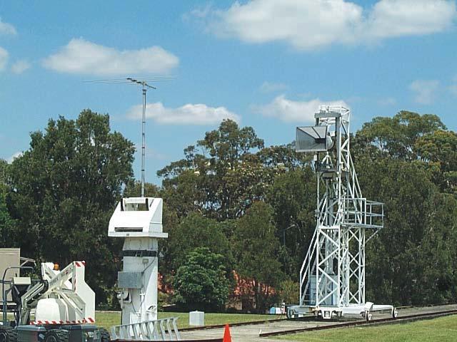
4 4 Rep. ITU-R BT.2138 Step 4: Both the AUT and SGH were then rotated to the next orientation angle. Step 5: The AUT was again scanned in azimuth through 360 to obtain a co-polar pattern with samples recorded every 1. Step 6: Steps 4 and 5 were repeated for the remaining orientation angles. The gain-normalized swept-frequency measurements of the antennas were measured on boresight at 0 orientation for frequencies between 620 MHz and 790 MHz. The measurements were conducted with a HP 8757D scalar network analyser and confirmed by measurements at discreet frequencies with an Agilent E4407B spectrum analyser. Two 1.5 m RG6 quad shield cables were used in the measurements; one with F type connectors for connection to antennas with F type balun inputs, and another with no connector on one end for connection to antennas with saddle type balun inputs. Both cables were measured with a HP 8510C vector network analyser as well as a minimum loss pad that was used to match impedances between the 75 Ω AUT to the 50 Ω system. The measurement procedure listed below was followed for each antenna tested. The SGH was modelled with mode-matching software to accurately predict its gain. The range length was set to 12 m and the AUT and the SGH were mounted in the vertical plane (H-plane) nominated as 0 orientation. A HP 8757D scalar network analyser was set up to sweep MHz with the detector calibrated for absolute power measurement. The transmit power into the SGH was measured, via a 20 db directional coupler, and the data saved to file. The received power at the AUT was measured at the output of the 75 to 50 Ω minimum loss pad was measured and the data saved to file. Owing to the risk of other signals being picked up by the wide band detector used on the scalar network analyser, an Agilent E4407B spectrum analyser was used to confirm the measured power levels at several discrete frequencies in the swept band. At each frequency the corrected gain was calculated from the ratio of transmitted and received powers after taking into account the losses in the measurement system (i.e. coupling factors, path loss, and the minimum loss pad) and the gain of the SGH. Care is taken with the measurement of each parameter to ensure that errors are minimized, but nevertheless, uncertainties remain. A number of factors contribute to the level of uncertainty in the measurements. These include errors in the measurement accuracy of the spectrum and scalar analysers, and the impact of range reflections on the measured levels. The estimated on-axis gain accuracy for these measurements is < 1 db. At different azimuth angles the accuracy in the level of the measured pattern may degrade due reflected signals; and will vary differently depending on frequency and polarization of the measured signal. Finally, the antennas with a centre mounting location required a small offset bracket to facilitate 135 of rotation, this bracket is shown in Fig. 2 along with a general overview of the measurement range shown in Figs. 3 and 4.

5 Rep. ITU-R BT


6 6 Rep. ITU-R BT Results Table 2 summarizes the gain normalized measurements, and lists the plots for the pattern cuts and swept responses. The discrete points on the swept response plots refer to the narrow-band spectrum analyser measurements used to confirm the gain.
7 Rep. ITU-R BT Antenna number Polarization (degrees) TABLE 2 Antenna measurement results Frequency (MHz) Gain (dbi) Plot number 0, 45, 90, , 45, 90, , 45, 90, , 45, 90, , 45, 90, , 45, 90, , 45, 90, , 45, 90, , 45, 90, , 45, 90, , 45, 90, , 45, 90, , 45, 90, , 45, 90, , 45, 90, (1) 0, 45, 90, , 45, 90, , 45, 90, , 45, 90, , 45, 90, , 45, 90, (2) 0, 45, 90, , 45, 90, (3) 0, 45, 90, (1) (2) (3) Tuneable UHF frequency range of MHz. Tuneable UHF frequency range of MHz. Tuneable UHF frequency range of MHz.
8 8 Rep. ITU-R BT.2138
9 Rep. ITU-R BT
10 10 Rep. ITU-R BT.2138
11 Rep. ITU-R BT
12 12 Rep. ITU-R BT.2138
13 Rep. ITU-R BT
14 14 Rep. ITU-R BT.2138
15 Rep. ITU-R BT
16 16 Rep. ITU-R BT.2138
17 Rep. ITU-R BT
18 18 Rep. ITU-R BT.2138
19 Rep. ITU-R BT
20 20 Rep. ITU-R BT.2138
21 Rep. ITU-R BT
22 22 Rep. ITU-R BT.2138
23 Rep. ITU-R BT
24 24 Rep. ITU-R BT.2138
25 Rep. ITU-R BT
26 26 Rep. ITU-R BT.2138
27 Rep. ITU-R BT
28 28 Rep. ITU-R BT.2138
29 Rep. ITU-R BT
30 30 Rep. ITU-R BT.2138
31 Rep. ITU-R BT
32 32 Rep. ITU-R BT.2138
33 Rep. ITU-R BT
34 34 Rep. ITU-R BT.2138
35 Rep. ITU-R BT
36 36 Rep. ITU-R BT.2138
37 Rep. ITU-R BT
38 38 Rep. ITU-R BT.2138
39 Rep. ITU-R BT
40 40 Rep. ITU-R BT.2138
41 Rep. ITU-R BT
42 42 Rep. ITU-R BT.2138
43 Rep. ITU-R BT
44 44 Rep. ITU-R BT Comments A number of aspects of the physical testing environment can have an effect on the measured radiation patterns. These include but are not limited to: range reflections differing with different polarization of the AUT; the proximity of the mounting and or offset bracket to the driven element; and the orientation of the AUT with respect to the mast on which it is supported, particularly when the E-field vector of the AUT is co-aligned with the metal mast such that the mast effectively becomes part of the antenna. Part way through the measurement program it was observed that a certain AUT was susceptible to noise generated by the measurement rotator during a swept frequency measurement using a broadband detector. Turning off the motor eliminated the noise, so all further swept frequency measurements were conducted when the measurement rotator was turned off. No further investigation was conducted into why this antenna was affected by noise, as it was outside the scope of the measurement program. It does however raise the issue of noise and the potential need to investigate, and perhaps improve, the noise immunity of the antennas. The measurement of low-frequency antennas with broad radiation patterns is a difficult problem. To minimize reflections into the test zone the research organization, CSIRO Australia, has tried to keep the distance between the range antenna and AUT to a minimum by measuring the on-axis ripple, keep the antennas as high as possible above the ground, and use as large a range antenna as practicable, i.e. a directive antenna. Nevertheless residual reflections can affect the measured patterns, where for example a 45 db reflection can produce a 1 db measurement error for a signal 20 db down from the peak. This is not thought to be a problem at the near in azimuth angles as the range length is short and precludes reflections from surrounding buildings, but at broader azimuth angles it is possible that residual reflections from buildings may influence the far-out side lobes. 6 Conclusions Recommendation ITU-R BT (1992) contains a mask for receiving antenna directivity that is to be used in the planning of terrestrial television services. This does not constitute a design specification for receiving antennas, but is an assumption about their directivity which affects the calculation of potential interference from other services into the broadcasting service. The mask from Recommendation ITU-R BT.419 for Bands IV and V is shown overlaid on the measured patterns in Plots 1 to 24. Clearly a number of antennas fit well with the mask, where others do not due to their broader patterns and lower gain, particularly at the lower measurement frequency. As only one antenna of each model was measured, it is unknown whether the measurement results reflect a broad cross-sectional sample of each antenna model. If, however, these measured results are taken to be indicative of antennas already in service, then it should be considered whether the mask of Recommendation ITU-R BT.419 continues to be appropriate for terrestrial television planning, or whether a relaxed mask to accommodate broader, lower-gain antennas, should be proposed. A relaxation of Recommendation ITU-R BT.419 may impact on other services in the UHF bands, and this effect should be carefully considered.
RECOMMENDATION ITU-R F *
 Rec. ITU-R F.699-6 1 RECOMMENATION ITU-R F.699-6 * Reference radiation patterns for fixed wireless system antennas for use in coordination studies and interference assessment in the frequency range from
You will need the following pieces of equipment to complete this experiment: Wilkinson power divider (3-port board with oval-shaped trace on it)
") UNIVERSITY OF TORONTO FACULTY OF APPLIED SCIENCE AND ENGINEERING The Edward S. Rogers Sr. Department of Electrical and Computer Engineering ECE422H1S: RADIO AND MICROWAVE WIRELESS SYSTEMS EXPERIMENT 1:
UNIVERSITY OF TORONTO FACULTY OF APPLIED SCIENCE AND ENGINEERING The Edward S. Rogers Sr. Department of Electrical and Computer Engineering ECE422H1S: RADIO AND MICROWAVE WIRELESS SYSTEMS EXPERIMENT 1:
Introduction Antenna Ranges Radiation Patterns Gain Measurements Directivity Measurements Impedance Measurements Polarization Measurements Scale
 Chapter 17 : Antenna Measurement Introduction Antenna Ranges Radiation Patterns Gain Measurements Directivity Measurements Impedance Measurements Polarization Measurements Scale Model Measurements 1 Introduction
The CReSIS Anechoic Chamber is located at: The University of Kansas. M2SEC building W 15 th St. Lawrence, KS
 The CReSIS Anechoic Chamber is located at: The University of Kansas M2SEC building 1536 W 15 th St Lawrence, KS 66045 Pattern Manual Antenna radiation pattern measurement 1. To open EMQuest, right click
ECC Recommendation (16)04
04") ECC Recommendation (16)04 Determination of the radiated power from FM sound broadcasting stations through field strength measurements in the frequency band 87.5 to 108 MHz Approved 17 October 2016 Edition
ECC Recommendation (16)04 Determination of the radiated power from FM sound broadcasting stations through field strength measurements in the frequency band 87.5 to 108 MHz Approved 17 October 2016 Edition
Model BiConiLog Antenna. User Manual
 Model 3149 BiConiLog Antenna User Manual ETS-Lindgren Inc. reserves the right to make changes to any products herein to improve functioning or design. Although the information in this document has been
Accuracy Estimation of Microwave Holography from Planar Near-Field Measurements
 Accuracy Estimation of Microwave Holography from Planar Near-Field Measurements Christopher A. Rose Microwave Instrumentation Technologies River Green Parkway, Suite Duluth, GA 9 Abstract Microwave holography
RECOMMENDATION ITU-R M * TECHNIQUES FOR MEASUREMENT OF UNWANTED EMISSIONS OF RADAR SYSTEMS. (Question ITU-R 202/8)
") Rec. ITU-R M.1177-2 1 RECOMMENDATION ITU-R M.1177-2* TECHNIQUES FOR MEASUREMENT OF UNWANTED EMISSIONS OF RADAR SYSTEMS (Question ITU-R 202/8) Rec. ITU-R M.1177-2 (1995-1997-2000) The ITU Radiocommunication
Rec. ITU-R M.1177-2 1 RECOMMENDATION ITU-R M.1177-2* TECHNIQUES FOR MEASUREMENT OF UNWANTED EMISSIONS OF RADAR SYSTEMS (Question ITU-R 202/8) Rec. ITU-R M.1177-2 (1995-1997-2000) The ITU Radiocommunication
RECOMMENDATION ITU-R M.1824 *
 Rec. ITU-R M.1824 1 RECOMMENDATION ITU-R M.1824 * System characteristics of television outside broadcast, electronic news gathering and electronic field production in the mobile service for use in sharing
ETSI ES V1.1.1 ( )
") ES 202 056 V1.1.1 (2005-01) Standard Electromagnetic compatibility and Radio spectrum Matters (ERM); Active antennas used for broadcast TV and sound reception from 47 MHz to 860 MHz 2 ES 202 056 V1.1.1
ES 202 056 V1.1.1 (2005-01) Standard Electromagnetic compatibility and Radio spectrum Matters (ERM); Active antennas used for broadcast TV and sound reception from 47 MHz to 860 MHz 2 ES 202 056 V1.1.1
Rec. ITU-R F RECOMMENDATION ITU-R F *
 Rec. ITU-R F.162-3 1 RECOMMENDATION ITU-R F.162-3 * Rec. ITU-R F.162-3 USE OF DIRECTIONAL TRANSMITTING ANTENNAS IN THE FIXED SERVICE OPERATING IN BANDS BELOW ABOUT 30 MHz (Question 150/9) (1953-1956-1966-1970-1992)
Milton Keynes Amateur Radio Society (MKARS)
") Milton Keynes Amateur Radio Society (MKARS) Intermediate Licence Course Feeders Antennas Matching (Worksheets 31, 32 & 33) MKARS Intermediate Licence Course - Worksheet 31 32 33 Antennas Feeders Matching
Milton Keynes Amateur Radio Society (MKARS) Intermediate Licence Course Feeders Antennas Matching (Worksheets 31, 32 & 33) MKARS Intermediate Licence Course - Worksheet 31 32 33 Antennas Feeders Matching
> StarLab. Multi-purpose Antenna Measurement Multi-protocol Antenna Development Linear Array Antenna Measurement OTA Testing
 TECHNOLOGY Near-field / Spherical Near-field / Cylindrical SOLUTIONS FOR Multi-purpose Antenna Measurement Multi-protocol Antenna Development Linear Array Antenna Measurement OTA Testing 18 StarLab: a
ELEC 477/677L Wireless System Design Lab Spring 2014
 ELEC 477/677L Wireless System Design Lab Spring 2014 Lab #5: Yagi-Uda Antenna Design Using EZNEC Introduction There are many situations, such as in point-to-point communication, where highly directional
Model 3180B Mini-Bicon Antenna User Manual
 Model 3180B Mini-Bicon Antenna User Manual Model 3180B with conical elements Model 3180B with cage elements ETS-Lindgren L.P. reserves the right to make changes to any product described herein in order
Boom Distance Influence on Yagi Antenna Dragoslav Dobričić, YU1AW (Serbia)
") Boom Distance Influence on Yagi Antenna Dragoslav Dobričić, YU1AW (Serbia) dragan@antennex.com Introduction In a previous article [1] we investigated boom radius influence on six Yagi antennas very similar
Boom Distance Influence on Yagi Antenna Dragoslav Dobričić, YU1AW (Serbia) dragan@antennex.com Introduction In a previous article [1] we investigated boom radius influence on six Yagi antennas very similar
Antenna Technology Bootcamp. NTA Show 2017 Denver, CO
 Antenna Technology Bootcamp NTA Show 2017 Denver, CO Review: How a slot antenna works The slot antenna is a TEM-Mode coaxial structure. Coupling structures inside the pylon will distort and couple to the
KULLIYYAH OF ENGINEERING
 KULLIYYAH OF ENGINEERING DEPARTMENT OF ELECTRICAL & COMPUTER ENGINEERING ANTENNA AND WAVE PROPAGATION LABORATORY (ECE 4103) EXPERIMENT NO 3 RADIATION PATTERN AND GAIN CHARACTERISTICS OF THE DISH (PARABOLIC)
WIESON TECHNOLOGIES CO., LTD.
 WIESON 3D CHAMBER TEST REPORT G121HT632-1 Page 1 of 2 I. Summary: This report to account for the measurement setup and result of the Antenna. The measurement setup includes s-parameter, pattern, and gain
APPENDIX 4 (REV.WRC-15) Consolidated list and tables of characteristics for use in the application of the procedures of Chapter III
 Consolidated list and tables of characteristics for use in the application of the procedures of Chapter III") AP4-1 APPENDI 4 (REV.WRC-15) Consolidated list and tables of characteristics for use in the application of the procedures of Chapter III 1 The substance of this Appendix is separated into two parts: one
AP4-1 APPENDI 4 (REV.WRC-15) Consolidated list and tables of characteristics for use in the application of the procedures of Chapter III 1 The substance of this Appendix is separated into two parts: one
RECOMMENDATION ITU-R SM Method for measurements of radio noise
 Rec. ITU-R SM.1753 1 RECOMMENDATION ITU-R SM.1753 Method for measurements of radio noise (Question ITU-R 1/45) (2006) Scope For radio noise measurements there is a need to have a uniform, frequency-independent
Broadband Antenna. Broadband Antenna. Chapter 4
 1 Chapter 4 Learning Outcome At the end of this chapter student should able to: To design and evaluate various antenna to meet application requirements for Loops antenna Helix antenna Yagi Uda antenna
SPHERICAL NEAR-FIELD MEASUREMENTS AT UHF FREQUENCIES WITH COMPLETE UNCERTAINTY ANALYSIS
 SPHERICAL NEAR-FIELD MEASUREMENTS AT UHF FREQUENCIES WITH COMPLETE UNCERTAINTY ANALYSIS Allen Newell, Patrick Pelland Nearfield Systems Inc. 19730 Magellan Drive, Torrance, CA 90502-1104 Brian Park, Ted
Yagi Antenna Elements Correction for Square Boom Dragoslav Dobričić, YU1AW
 Yagi Antenna Elements Correction for Square Boom Dragoslav Dobričić, YU1AW dragan@antennex.com Introduction I n the previous December 2009 article [1] we showed how the boom caused influences on elements
Numerical Calibration of Standard Gain Horns and OEWG Probes
 Numerical Calibration of Standard Gain Horns and OEWG Probes Donald G. Bodnar dbodnar@mi-technologies.com MI Technologies 1125 Satellite Blvd, Suite 100 Suwanee, GA 30024 ABSTRACT The gain-transfer technique
RECOMMENDATION ITU-R M.1652 *
 Rec. ITU-R M.1652 1 RECOMMENDATION ITU-R M.1652 * Dynamic frequency selection (DFS) 1 in wireless access systems including radio local area networks for the purpose of protecting the radiodetermination
Exercise 1-3. Radar Antennas EXERCISE OBJECTIVE DISCUSSION OUTLINE DISCUSSION OF FUNDAMENTALS. Antenna types
 Exercise 1-3 Radar Antennas EXERCISE OBJECTIVE When you have completed this exercise, you will be familiar with the role of the antenna in a radar system. You will also be familiar with the intrinsic characteristics
TPV-SFN Series Low RFR VHF Slot Pylon Antennas
 Channel 7-13 (Band III) Low RFR VHF Slot Antenna Omni-directional and Directional Patterns Available Top or Side Mount Models Horizontal, Elliptical, or Circular Polarization Available TPV-SFN Series Low
CHAPTER 8 ANTENNAS 1
 CHAPTER 8 ANTENNAS 1 2 Antennas A good antenna works A bad antenna is a waste of time & money Antenna systems can be very inexpensive and simple They can also be very expensive 3 Antenna Considerations
PROBE CORRECTION EFFECTS ON PLANAR, CYLINDRICAL AND SPHERICAL NEAR-FIELD MEASUREMENTS
 PROBE CORRECTION EFFECTS ON PLANAR, CYLINDRICAL AND SPHERICAL NEAR-FIELD MEASUREMENTS Greg Hindman, David S. Fooshe Nearfield Systems Inc. 133 E. 223rd Street Bldg 524 Carson, CA 9745 USA (31) 518-4277
Chapter 6 Broadband Antenna. 1. Loops antenna 2. Heliksantenna 3. Yagi uda antenna
 Chapter 6 Broadband Antenna 1. Loops antenna 2. Heliksantenna 3. Yagi uda antenna 1 Design A broadband antenna should have acceptable performance (determined by its pattern, gain and/or feed-point impedance)
772D coaxial dual-directional coupler 773D coaxial directional coupler. 775D coaxial dual-directional coupler 776D coaxial dual-directional coupler
 72 772D coaxial dual-directional coupler 773D coaxial directional coupler 775D coaxial dual-directional coupler 776D coaxial dual-directional coupler 777D coaxial dual-directional coupler 778D coaxial
Using Frequency Diversity to Improve Measurement Speed Roger Dygert MI Technologies, 1125 Satellite Blvd., Suite 100 Suwanee, GA 30024
 Using Frequency Diversity to Improve Measurement Speed Roger Dygert MI Technologies, 1125 Satellite Blvd., Suite 1 Suwanee, GA 324 ABSTRACT Conventional antenna measurement systems use a multiplexer or
Amateur Radio License. Propagation and Antennas
 Amateur Radio License Propagation and Antennas Todays Topics Propagation Antennas Propagation Modes Ground wave Low HF and below, ground acts as waveguide Line-of-Sight (LOS) VHF and above, radio waves
Traveling Wave Antennas
 Traveling Wave Antennas Antennas with open-ended wires where the current must go to zero (dipoles, monopoles, etc.) can be characterized as standing wave antennas or resonant antennas. The current on these
T- DualScan. StarLab
 T- DualScan StarLab StarLab is the ultimate tool for antenna pattern measurements in laboratories and production environments where space is limited, cost is critical, and the flexibility of a portable
P. 1 of 18 REPORT 1.1. TV ANTENNA RECONSTITUTION P. 1 of 18. Commercial in Confidence SAMPLE SITE (TV). 3 MARCH 2017.
. 3 MARCH 2017.") P. 1 of 18 Commercial in Confidence REPORT 1.1 TV ANTENNA RECONSTITUTION P. 1 of 18 SAMPLE SITE (TV). 3 MARCH 2017. 1/ EXECUTIVE SUMMARY Sixarms has been commissioned by the Client to verify the performance
P. 1 of 18 Commercial in Confidence REPORT 1.1 TV ANTENNA RECONSTITUTION P. 1 of 18 SAMPLE SITE (TV). 3 MARCH 2017. 1/ EXECUTIVE SUMMARY Sixarms has been commissioned by the Client to verify the performance
CHAPTER 5 THEORY AND TYPES OF ANTENNAS. 5.1 Introduction
 CHAPTER 5 THEORY AND TYPES OF ANTENNAS 5.1 Introduction Antenna is an integral part of wireless communication systems, considered as an interface between transmission line and free space [16]. Antenna
METHODS TO ESTIMATE AND REDUCE LEAKAGE BIAS ERRORS IN PLANAR NEAR-FIELD ANTENNA MEASUREMENTS
 METHODS TO ESTIMATE AND REDUCE LEAKAGE BIAS ERRORS IN PLANAR NEAR-FIELD ANTENNA MEASUREMENTS Allen C. Newell Newell Near-Field Consultants 235 Vassar Drive, Boulder CO 835 Jeff Guerrieri and Katie MacReynolds
A DUAL-PORTED PROBE FOR PLANAR NEAR-FIELD MEASUREMENTS
 A DUAL-PORTED PROBE FOR PLANAR NEAR-FIELD MEASUREMENTS W. Keith Dishman, Doren W. Hess, and A. Renee Koster ABSTRACT A dual-linearly polarized probe developed for use in planar near-field antenna measurements
BHARATHIDASAN ENGINEERING COLLEGE NATTARAMPALLI Frequently Asked Questions (FAQ) Unit 1
 Unit 1") BHARATHIDASAN ENGINEERING COLLEGE NATTARAMPALLI 635854 Frequently Asked Questions (FAQ) Unit 1 Degree / Branch : B.E / ECE Sem / Year : 3 rd / 6 th Sub Name : Antennas & Wave Propagation Sub Code : EC6602
BHARATHIDASAN ENGINEERING COLLEGE NATTARAMPALLI 635854 Frequently Asked Questions (FAQ) Unit 1 Degree / Branch : B.E / ECE Sem / Year : 3 rd / 6 th Sub Name : Antennas & Wave Propagation Sub Code : EC6602
GAIN COMPARISON MEASUREMENTS IN SPHERICAL NEAR-FIELD SCANNING
 GAIN COMPARISON MEASUREMENTS IN SPHERICAL NEAR-FIELD SCANNING ABSTRACT by Doren W. Hess and John R. Jones Scientific-Atlanta, Inc. A set of near-field measurements has been performed by combining the methods
Systems characteristics of automotive radars operating in the frequency band GHz for intelligent transport systems applications
 Recommendation ITU-R M.257-1 (1/218) Systems characteristics of automotive s operating in the frequency band 76-81 GHz for intelligent transport systems applications M Series Mobile, radiodetermination,
CHARACTERISATION OF IN -HOUSE EMC TESTING FACILITIES FOR PRODUCT DESIGNERS. Paul Kay* and Andrew Nafalski**
 CHARACTERISATION OF IN -HOUSE EMC TESTING FACILITIES FOR PRODUCT DESIGNERS Paul Kay* and Andrew Nafalski** *Austest Laboratories, Adelaide **University of South Australia School of Electrical and Information
RECOMMENDATION ITU-R BT.1832 * Digital video broadcast-return channel terrestrial (DVB-RCT) deployment scenarios and planning considerations
 deployment scenarios and planning considerations") Rec. ITU-R BT.1832 1 RECOMMENDATION ITU-R BT.1832 * Digital video broadcast-return channel terrestrial (DVB-RCT) deployment scenarios and planning considerations (Question ITU-R 16/6) (2007) Scope This
Rec. ITU-R BT.1832 1 RECOMMENDATION ITU-R BT.1832 * Digital video broadcast-return channel terrestrial (DVB-RCT) deployment scenarios and planning considerations (Question ITU-R 16/6) (2007) Scope This
RECOMMENDATION ITU-R F RADIO-FREQUENCY CHANNEL ARRANGEMENTS FOR RADIO-RELAY SYSTEMS OPERATING IN THE 13 GHz FREQUENCY BAND
 Rec. ITU-R F.497-6 RECOMMENDATION ITU-R F.497-6 RADIO-FREQUENCY CHANNEL ARRANGEMENTS FOR RADIO-RELAY SYSTEMS OPERATING IN THE 3 GHz FREQUENCY BAND (Question ITU-R 36/9) (974-978-982-990-992-995-999) Rec.
DF Antennas - Datasheet. Datasheet
 DF Antennas - Datasheet Datasheet To cover a wide frequency range with high sensitivity, Narda offers several directional antennas. Each antenna is optimized for their particular frequency range with regard
Antenna Performance. Antenna Performance... 3 Gain... 4 Radio Power and the FCC... 6 Link Margin Calculations... 7 The Banner Way... 8 Glossary...
 Antenna Performance Antenna Performance... 3 Gain... 4 Radio Power and the FCC... 6 Link Margin Calculations... 7 The Banner Way... 8 Glossary... 9 06/15/07 135765 Introduction In this new age of wireless
Recommendation ITU-R SA (07/2017)
") Recommendation ITU-R SA.1026-5 (07/2017) Aggregate interference criteria for space-to- Earth data transmission systems operating in the Earth exploration-satellite and meteorological-satellite services
Recommendation ITU-R SA.1026-5 (07/2017) Aggregate interference criteria for space-to- Earth data transmission systems operating in the Earth exploration-satellite and meteorological-satellite services
RECOMMENDATION ITU-R BT.655-7
 Rec. ITU-R BT.655-7 1 RECOMMENDATION ITU-R BT.655-7 Radio-frequency protection ratios for AM vestigial sideband terrestrial television systems interfered with by unwanted analogue vision signals and their
High Performance Wide-band self-matched Yagi Antennas - with a focus on pattern symmetry
 High Performance Wide-band self-matched Yagi Antennas - with a focus on pattern symmetry by Justin Johnson, G0KSC I must say it has been good to see some long-standing Yagi developers adopt new optimisation
Measurement Procedure & Test Equipment Used
 Measurement Procedure & Test Equipment Used Except where otherwise stated, all measurements are made following the Electronic Industries Association (EIA) Minimum Standard for Portable/Personal Land Mobile
BROADBAND GAIN STANDARDS FOR WIRELESS MEASUREMENTS
 BROADBAND GAIN STANDARDS FOR WIRELESS MEASUREMENTS James D. Huff Carl W. Sirles The Howland Company, Inc. 4540 Atwater Court, Suite 107 Buford, Georgia 30518 USA Abstract Total Radiated Power (TRP) and
FCC CFR47 PART 15 SUBPART C INDUSTRY CANADA RSS-GEN AND RSS-210 CERTIFICATION TEST REPORT FOR BROADCOM BLUETOOTH MODULE MODEL NUMBER: BCM92046MD
 FCC CFR47 PART 15 SUBPART C INDUSTRY CANADA RSS-GEN AND RSS-210 CERTIFICATION TEST REPORT FOR BROADCOM BLUETOOTH MODULE MODEL NUMBER: BCM92046MD IC #: 4324A-BRCM1029 REPORT NUMBER: 07U11199-1C ISSUE DATE:
FCC 47 CFR PART 15 SUBPART C INDUSTRY CANADA RSS-210 ISSUE 8 BLUETOOTH LOW ENERGY CERTIFICATION TEST REPORT FOR. 2.4GHz LE MODULE MODEL NUMBER: RN4020
 FCC 47 CFR PART 15 SUBPART C INDUSTRY CANADA RSS-210 ISSUE 8 BLUETOOTH LOW ENERGY CERTIFICATION TEST REPORT FOR 2.4GHz LE MODULE MODEL NUMBER: RN4020 REPORT NUMBER: 14U17191-1 ISSUE DATE: MARCH 21, 2014
Double-Ridged Waveguide Horn
 Model 3106 200 MHz 2 GHz Uniform Gain Power Handling up to 1.6 kw Model 3115 1 GHz 18 GHz Low VSWR Model 3116 18 GHz 40 GHz Quality Construction M O D E L 3 1 0 6 Double-Ridged Waveguide Horn PROVIDING
MICROWAVE MICROWAVE TRAINING BENCH COMPONENT SPECIFICATIONS:
 Microwave section consists of Basic Microwave Training Bench, Advance Microwave Training Bench and Microwave Communication Training System. Microwave Training System is used to study all the concepts of
Spectrum limit masks for digital terrestrial television broadcasting
 Recommendation ITU-R BT.1206-1 (01/2013) Spectrum limit masks for digital terrestrial television broadcasting BT Series Broadcasting service (television) ii Rec. ITU-R BT.1206-1 Foreword The role of the
Exercise 4. Angle Tracking Techniques EXERCISE OBJECTIVE
 Exercise 4 Angle Tracking Techniques EXERCISE OBJECTIVE When you have completed this exercise, you will be familiar with the principles of the following angle tracking techniques: lobe switching, conical
Mathematical models for radiodetermination radar systems antenna patterns for use in interference analyses
 Recommendation ITU-R M.1851-1 (1/18) Mathematical models for radiodetermination radar systems antenna patterns for use in interference analyses M Series Mobile, radiodetermination, amateur and related
P300/P350 Series. Vertically Polarized FM Antenna. Features. Characteristics
 Vertically Polarized FM Features Low VSWR, superior VSWR band width, minimal weather related VSWR problems Fully pressurized, internal feed, welded feed connections, series fed radiating elements High
Keysight Technologies Pulsed Antenna Measurements Using PNA Network Analyzers
 Keysight Technologies Pulsed Antenna Measurements Using PNA Network Analyzers White Paper Abstract This paper presents advances in the instrumentation techniques that can be used for the measurement and
Antenna Design Seminar
 Antenna Design Seminar What we are going to cover This seminar will cover the design concepts of a variety of broadcast antennas that relates to the design of TV and FM antennas. We will first look at
ANTENNAS. I will mostly be talking about transmission. Keep in mind though, whatever is said about transmission is true of reception.
 Reading 37 Ron Bertrand VK2DQ http://www.radioelectronicschool.com ANTENNAS The purpose of an antenna is to receive and/or transmit electromagnetic radiation. When the antenna is not connected directly
Technician License Course Chapter 4. Lesson Plan Module 9 Antenna Fundamentals, Feed Lines & SWR
 Technician License Course Chapter 4 Lesson Plan Module 9 Antenna Fundamentals, Feed Lines & SWR The Antenna System Antenna: Transforms current into radio waves (transmit) and vice versa (receive). Feed
UNIVERSITI MALAYSIA PERLIS
 UNIVERSITI MALAYSIA PERLIS SCHOOL OF COMPUTER & COMMUNICATIONS ENGINEERING EKT 341 LABORATORY MODULE LAB 2 Antenna Characteristic 1 Measurement of Radiation Pattern, Gain, VSWR, input impedance and reflection
Narda DF Antennas - Datasheet. Datasheet
 Narda DF Antennas - Datasheet Datasheet To cover a wide frequency range with high sensitivity, Narda offers several directional antennas. Each antenna is optimized for their particular frequency range
GPS Active Antenna With GPRS Measurement Report
 GPS Active Antenna With GPRS Measurement Report Summary: This report is to account for the measurement setup and results of 4x23mm and mm height GPS active antenna combined with GPRS antenna measurement.
Design of a 915 MHz Patch Antenna with structure modification to increase bandwidth
 Fidel Amezcua Professor: Ray Kwok Electrical Engineering 172 28 May 2010 Design of a 915 MHz Patch Antenna with structure modification to increase bandwidth 1. Introduction The objective presented in this
Half-Wave Dipole. Radiation Resistance. Antenna Efficiency
 Antennas Simple Antennas Isotropic radiator is the simplest antenna mathematically Radiates all the power supplied to it, equally in all directions Theoretical only, can t be built Useful as a reference:
Trees, vegetation, buildings etc.
 EMC Measurements Test Site Locations Open Area (Field) Test Site Obstruction Free Trees, vegetation, buildings etc. Chamber or Screened Room Smaller Equipments Attenuate external fields (about 100dB) External
Recommendation ITU-R M (05/2011)
") Recommendation ITU-R M.1652-1 (05/2011) Dynamic frequency selection in wireless access systems including radio local area networks for the purpose of protecting the radiodetermination service in the 5
Recommendation ITU-R M.1652-1 (05/2011) Dynamic frequency selection in wireless access systems including radio local area networks for the purpose of protecting the radiodetermination service in the 5
Input Return Loss, db > 26 Narrowband to Narrowband Isolation, db > 30
 Band III (VHF) TV Commutating Line Combiner 174-222 MHz CC VHF Series This style of circuit provides a relatively low cost combiner which is ideal, provided the frequency spacing is not too close. Compact,
4/29/2012. General Class Element 3 Course Presentation. Ant Antennas as. Subelement G9. 4 Exam Questions, 4 Groups
 General Class Element 3 Course Presentation ti ELEMENT 3 SUB ELEMENTS General Licensing Class Subelement G9 Antennas and Feedlines 4 Exam Questions, 4 Groups G1 Commission s Rules G2 Operating Procedures
Technical and operational characteristics of land mobile MF/HF systems
 Recommendation ITU-R M.1795 (03/2007) Technical and operational characteristics of land mobile MF/HF systems M Series Mobile, radiodetermination, amateur and related satellite services ii Rec. ITU-R M.1795
Upgraded Planar Near-Field Test Range For Large Space Flight Reflector Antennas Testing from L to Ku-Band
 Upgraded Planar Near-Field Test Range For Large Space Flight Reflector Antennas Testing from L to Ku-Band Laurent Roux, Frédéric Viguier, Christian Feat ALCATEL SPACE, Space Antenna Products Line 26 avenue
Accredited Standards Committee C63 - EMC
 Draft C63.-5-201x Annex N Site-Specific Qualification Procedure for Hybrid Antennas (intended to be used for the making of ANSI C63.4-201x Final Compliance Measurements) Harry H. Hodes, NCE Principal EMC
BASICS OF ANTENNAS Lecture Note 1
 BASICS OF ANTENNAS Lecture Note 1 INTRODUCTION Antennas are devices that are capable of launching RF (radio frequency) energy into space and detect it as well. How well an antenna is able to launch RF
Optimum use of frequency thanks to reliable forecasts in planning
 BROADCASTING Coverage measurement systems FMTV Optimum use of frequency thanks to reliable forecasts in planning New sites for FM and TV broadcasting are planned with the aid of special software that predicts
RECOMMENDATION ITU-R S.1512
 Rec. ITU-R S.151 1 RECOMMENDATION ITU-R S.151 Measurement procedure for determining non-geostationary satellite orbit satellite equivalent isotropically radiated power and antenna discrimination The ITU
Cell Extender Antenna System Design Guide Lines
 Cell Extender Antenna System Design Guide Lines 1. General The design of an Antenna system for a Cell Extender site needs to take into account the following specific factors: a) The systems input and output
Dr. John S. Seybold. November 9, IEEE Melbourne COM/SP AP/MTT Chapters
 Antennas Dr. John S. Seybold November 9, 004 IEEE Melbourne COM/SP AP/MTT Chapters Introduction The antenna is the air interface of a communication system An antenna is an electrical conductor or system
REPORT ITU-R BO Multiple-feed BSS receiving antennas
 Rep. ITU-R BO.2102 1 REPORT ITU-R BO.2102 Multiple-feed BSS receiving antennas (2007) 1 Introduction This Report addresses technical and performance issues associated with the design of multiple-feed BSS
Characteristics of and protection criteria for systems operating in the mobile service in the frequency range GHz
 Recommendation ITU-R M.2068-0 (02/2015) Characteristics of and protection criteria for systems operating in the mobile service in the frequency range 14.5-15.35 GHz M Series Mobile, radiodetermination,
EUROPEAN pr ETS TELECOMMUNICATION August 1996 STANDARD
 DRAFT EUROPEAN pr ETS 300 784 TELECOMMUNICATION August 1996 STANDARD Source: ETSI TC-SES Reference: DE/SES-00020 ICS: 33.060.30 Key words: broadcasting, BSS, DTH, earth station, FSS, LNB, radio, receiver,
Update of the compatibility study between RLAN 5 GHz and EESS (active) in the band MHz
 in the band MHz") ECC Electronic Communications Committee CEPT CPG-5 PTD CPG-PTD(4)23 CPG-5 PTD #6 Luxembourg, 28 April 2 May 204 Date issued: 22 April 204 Source: Subject: France Update of the compatibility study between
ECC Electronic Communications Committee CEPT CPG-5 PTD CPG-PTD(4)23 CPG-5 PTD #6 Luxembourg, 28 April 2 May 204 Date issued: 22 April 204 Source: Subject: France Update of the compatibility study between
INDOOR AUTOMATIC F-16 FIRE CONTROL ANTENNA AND RADOME TEST FACILITIES
 INDOOR AUTOMATIC F-16 FIRE CONTROL ANTENNA AND RADOME TEST FACILITIES ABSTRACT by Joseph J. Anderson MI Technologies was selected by the United States Air Force to design and install a complete turn-key
EMG4066:Antennas and Propagation Exp 1:ANTENNAS MMU:FOE. To study the radiation pattern characteristics of various types of antennas.
 OBJECTIVES To study the radiation pattern characteristics of various types of antennas. APPARATUS Microwave Source Rotating Antenna Platform Measurement Interface Transmitting Horn Antenna Dipole and Yagi
Amplitude Calibration - Measuring Antenna Temperature R.S. Flagg, RF Associates, March 2012 Radio-SkyPipe Units (SPU)
") Amplitude Calibration - Measuring Antenna Temperature R.S. Flagg, RF Associates, March 2012 The Jove radio telescope is designed to receive radio noise bursts from Jupiter and the Sun and also radio noise
Amplitude Calibration - Measuring Antenna Temperature R.S. Flagg, RF Associates, March 2012 The Jove radio telescope is designed to receive radio noise bursts from Jupiter and the Sun and also radio noise
RECOMMENDATION ITU-R M.1654 *
 Rec. ITU-R M.1654 1 Summary RECOMMENDATION ITU-R M.1654 * A methodology to assess interference from broadcasting-satellite service (sound) into terrestrial IMT-2000 systems intending to use the band 2
Antennas 101 Don t Be a 0.97 db Weakling! Ward Silver NØAX
 Antennas 101 Don t Be a 0.97 db Weakling! Ward Silver NØAX Overview Antennas 101 2 Overview Basic Antennas: Ground Plane / Dipole How Gain and Nulls are Formed How Phased Arrays Work How Yagis Work (simplified)
NXDN Signal and Interference Contour Requirements An Empirical Study
 NXDN Signal and Interference Contour Requirements An Empirical Study Icom America Engineering December 2007 Contents Introduction Results Analysis Appendix A. Test Equipment Appendix B. Test Methodology
Screening Attenuation When enough is enough
 Screening Attenuation When enough is enough Anders Møller-Larsen, Ph.D. M.Sc. E.E. Product Manager, Coax Network Introduction This white paper describes the requirements to screening attenuation of cables
AC Wire Carrier Current Devices (Unintentional Radiators)
") Issue 3 July 2018 Spectrum Management and Telecommunications Interference-Causing Equipment Standard AC Wire Carrier Current Devices (Unintentional Radiators) Aussi disponible en français NMB-006 Preface
Issue 3 July 2018 Spectrum Management and Telecommunications Interference-Causing Equipment Standard AC Wire Carrier Current Devices (Unintentional Radiators) Aussi disponible en français NMB-006 Preface
Real World Results from a Signal Measurement Drone
 Real World Results from a Signal Measurement Drone Presented by Ian Gair SixArms IEEE BTS October 2017 1 Outline of this Presentation What we are measuring Quick recap of Drone Based measurements Case
Technician License. Course
 Technician License Course Technician License Course Chapter 4 Lesson Plan Module - 9 Antenna Fundamentals Feed Lines & SWR The Antenna System The Antenna System Antenna: Transforms current into radio waves
Newsletter 2.3. Antenna Magus version 2.3 released! New antennas in Version 2.3. Potter horn. Circularly polarised rectangular-biquad antenna
 Newsletter 2.3 October 2010 Antenna Magus version 2.3 released! An update to Antenna Magus, version 2.3, is now available for download. This update features 10 new antennas, as opposed to the usual 6.
The Reverse Polarity TNC(m) RF connector can be easily secured or removed from equipment in the field by a single gloved hand, no tools required.
 RF connector can be easily secured or removed from equipment in the field by a single gloved hand, no tools required.") Overview Southwest Antennas is a half wave dipole omni antenna with a frequency range of 1.35 to 1.40 GHz and 2.15 dbi of peak gain. This product features an integrated RF bandpass filter to help eliminate
Overview Southwest Antennas is a half wave dipole omni antenna with a frequency range of 1.35 to 1.40 GHz and 2.15 dbi of peak gain. This product features an integrated RF bandpass filter to help eliminate
Range Considerations for RF Networks
 TI Technology Days 2010 Range Considerations for RF Networks Richard Wallace Abstract The antenna can be one of the most daunting components of wireless designs. Most information available relates to large
A Method for Gain over Temperature Measurements Using Two Hot Noise Sources
 A Method for Gain over Temperature Measurements Using Two Hot Noise Sources Vince Rodriguez and Charles Osborne MI Technologies: Suwanee, 30024 GA, USA vrodriguez@mitechnologies.com Abstract P Gain over