EME ON 77.5 Ghz. Sergei RW3BP, EME Meeting in Orebro, Sweden, May First of all few words about difficulties we have for EME on this band.
|
|
|
- Joy Jordan
- 5 years ago
- Views:
Transcription
1 EME ON 77.5 Ghz Sergei RW3BP, EME Meeting in Orebro, Sweden, May First of all few words about difficulties we have for EME on this band. You can see formula for signal to noise ratio. It is based on well known Radar equation for the Moon as a target. In this case it is simplified formula for fixed band, for fixed bandwidth of receiver, for fixed distance to the moon. All constant values are in general coefficient "M" and I left here only variable things. Really Radar cross section is also constant on all low bands but on this band it is not true. Let me remind you that radar cross section for EME is square of the moon disk multiplied by lunar reflection coefficient. For all bands lunar reflection coefficient is about 7 %. Let us consider now my case. Transmitter power 60 W, system noise temperature about 700K and antenna gain 62 db (one and half million). If to calculate signal to noise for echo the same way as on lower bands we'll get "0 db" for 2.5 khz bandwidth of receiver. It is good ratio. On 23cm it is easy copy SSB signal. But real life is much worse. First problem is reducing of radar cross section. Second picture shows two examples of moon illumination.

2 It is for two bands 5.7 GHz and 77.5 GHz and for my 2.4 m dish. It is easy to see what is difference for these bands. For 5.7 GHz the moon is small target and radar cross section of the moon is constant and not depends on antenna gain. On 77.5 GHz it is illuminated only part of the moon surface and radar cross section is function of antenna gain. More gain - less cross section. In first approximation this effect is begin when beam width of antenna is equal to angular size of the moon or when it is equal to 0.5 degree. Really only central part of the moon disk is reflect radio waves and it can be some equal diameter of the moon. For optical band it is nearly full diameter. On 77.5 GHz it is about 75% of the full diameter. On low bands the moon is reflect as a smooth shiny ball and equal diameter is small. Well, 75% of angular size of the Moon is degree. So on 77.5 GHz band starting from this beam width we'll get decreasing of cross section proportional to increasing of antenna gain. For my dish with 0.12 deg beam width we get echo signal loss about -10 db. Next problem is atmosphere loss. It is negligible on low bands but here it is very important. For 30 degrees elevation of antenna and for standard atmosphere it is -6.5 db loss in summer time and -2.5 db in winter time. It is for no rain and no clouds of course. Third problem is moon libration signal width. On 77.5 GHz it can be up to 1.5 khz on my latitude. Fortunately it can be decreased by narrow beam antenna. In my case it is

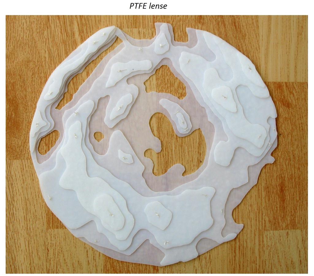
3 decreased from 4 to 5 times. BTW it is funny to tune received frequency by moving antenna from one edge (one Doppler shift) of the moon disk to another (another Doppler shift). And this is why the moon tracking must be accurate and smooth to get straight trace on Spectran. In my tests maximum libration signal width was about 250 Hz. Not sure how to calculate this loss. If standard brain filter for CW is about 50 Hz the loss will be about 5 times or -7dB. If to summarize all these losses we get db S/N in summer time and db S/ N in winter time. It is really not easy band and not many ways to improve results. Transmitter: 60 W is very high power for this band and I not see how to increase it. For me it is more important to save it because I have no spare one. It is a long story how I get power from this TWT. It is some pilot unit and there were some design errors in it. Antenna: It is a luck that my 2.4 m dish is now workable on this band. First result was very poor and I spent a lot of time trying to improve antenna. Even tried to use dielectric lens for correction. And all this is impossible without proper beacon. Sun and moon are too big for this band. So 2.4 m dish is limit for me now.

4


5

6 Receiver: There are some reserve there. I use not very new chips by UMS in LNA and now it is possible to improve it. I hope it can be improved from 5dB to 3dB noise figer. Also it is possible to try cooling. But there is also a limit. Antenna noise temperature is fully determined by moon noise. If to add atmosphere loss noise we get more then 200K for antenna and this is a limit. Finally I can say that two way QSO is possible on this band but it is hard work. The next is video. It is recorded in February
The Excitement & Challenges of 24 GHz EME. By Al Ward W5LUA August 17, 2012
 The Excitement & Challenges of 24 GHz EME By Al Ward W5LUA August 17, 2012 Introduction History Early Activity Present Activity Equipment Challenges Summary The First 24 GHz EME QSO The First 24 GHz EME
77 GHz EME at WA3ZKR/4 at Morehead State University
 77 GHz EME at WA3ZKR/4 at Morehead State University Al Ward W5LUA October 19, 2013 WWW..ORG 1 Introduction After some discussion with Jeff at MUD and subsequent approval by the folks at Morehead State
The VK3UM Radiation and System Performance Calculator
 The VK3UM Radiation and System Performance Calculator 1. Disclaimer... 2 2. Background... 2 3. Calculations... 2 4. Features... 2 5. Default Parameters... 3 6. Parameter Description... 4 7. On Axis Exclusion
255 km Aircraft Scatter QSO on 24 GHz
 255 km Aircraft Scatter QSO on 24 GHz First crossing of Bass Strait on 24 GHz By Rex Moncur VK7MO and David Smith VK3HZ On 13 March 2012, VK3HZ at Mt Liptrap near Wilson s Promontory in Victoria worked
The Rise and Rise of 6cm EME. Peter Blair G3LTF
 The Rise and Rise of 6cm EME Peter Blair G3LTF The Rise and Rise of 6cm EME G3LTF EME a brief history Why 6cm EME? Some 6cm issues Current Systems, Dishes and Feeds Transverters, LNAs and Transmitters
Amateur Pulsar Detection With EME Equipment
 Amateur Pulsar Detection With EME Equipment Pulsar: Neutron star with offset between magnetic and rotation axis emitting radio waves in a cone (lighthouse effect) Neutron star End of star lifetime: Supernova
RECOMMENDATION ITU-R F.1819
 Rec. ITU-R F.1819 1 RECOMMENDATION ITU-R F.1819 Protection of the radio astronomy service in the 48.94-49.04 GHz band from unwanted emissions from HAPS in the 47.2-47.5 GHz and 47.9-48.2 GHz bands * (2007)
Working Small Stations on 10 and 24 GHz EME with the help of WSJT
 Working Small Stations on 10 and 24 GHz EME with the help of WSJT Al Ward W5LUA October 19, 2013 Morehead State University Morehead, Kentucky The Bands Band Frequency Range Weak signal work in NA 33 cm
ANTENNA INTRODUCTION / BASICS
 ANTENNA INTRODUCTION / BASICS RULES OF THUMB: 1. The Gain of an antenna with losses is given by: 2. Gain of rectangular X-Band Aperture G = 1.4 LW L = length of aperture in cm Where: W = width of aperture
Ch. III - Limits of single polarity antennas in the VHF and UHF bands
 Ch. III - Limits of single polarity antennas in the VHF and UHF bands Ch. I 2014 QSB origins 2 m Faraday Ch. II 2016 Extension of Excel sheet to VHF and UHF bands From studies by Giorgio Marchi, IK1UWL
ATS 351 Lecture 9 Radar
 ATS 351 Lecture 9 Radar Radio Waves Electromagnetic Waves Consist of an electric field and a magnetic field Polarization: describes the orientation of the electric field. 1 Remote Sensing Passive vs Active
Aperture Antennas. Reflectors, horns. High Gain Nearly real input impedance. Huygens Principle
 Antennas 97 Aperture Antennas Reflectors, horns. High Gain Nearly real input impedance Huygens Principle Each point of a wave front is a secondary source of spherical waves. 97 Antennas 98 Equivalence
Lecture Topics. Doppler CW Radar System, FM-CW Radar System, Moving Target Indication Radar System, and Pulsed Doppler Radar System
 Lecture Topics Doppler CW Radar System, FM-CW Radar System, Moving Target Indication Radar System, and Pulsed Doppler Radar System 1 Remember that: An EM wave is a function of both space and time e.g.
VHF/UHF Beyond FM Bob Witte KØNR Page 1
 VHF/UHF Beyond FM Technical Coordinator Colorado Section Page 1 Objective The objective of this presentation is to provide an introduction to operating on VHF/UHF, going beyond the usual FM / Repeater
Multi Band Passive Forward Scatter Radar
 Multi Band Passive Forward Scatter Radar S. Hristov, A. De Luca, M. Gashinova, A. Stove, M. Cherniakov EESE, University of Birmingham Birmingham, B15 2TT, UK m.cherniakov@bham.ac.uk Outline Multi-Band
MOBILE RAPID-SCANNING X-BAND POLARIMETRIC (RaXPol) DOPPLER RADAR SYSTEM Andrew L. Pazmany 1 * and Howard B. Bluestein 2
 DOPPLER RADAR SYSTEM Andrew L. Pazmany 1 * and Howard B. Bluestein 2") 16B.2 MOBILE RAPID-SCANNING X-BAND POLARIMETRIC (RaXPol) DOPPLER RADAR SYSTEM Andrew L. Pazmany 1 * and Howard B. Bluestein 2 1 ProSensing Inc., Amherst, Massachusetts 2 University of Oklahoma, Norman,
16B.2 MOBILE RAPID-SCANNING X-BAND POLARIMETRIC (RaXPol) DOPPLER RADAR SYSTEM Andrew L. Pazmany 1 * and Howard B. Bluestein 2 1 ProSensing Inc., Amherst, Massachusetts 2 University of Oklahoma, Norman,
RECOMMENDATION ITU-R S.733-1* (Question ITU-R 42/4 (1990))**
)**") Rec. ITU-R S.733-1 1 RECOMMENDATION ITU-R S.733-1* DETERMINATION OF THE G/T RATIO FOR EARTH STATIONS OPERATING IN THE FIXED-SATELLITE SERVICE (Question ITU-R 42/4 (1990))** Rec. ITU-R S.733-1 (1992-1993)
Rec. ITU-R S.733-1 1 RECOMMENDATION ITU-R S.733-1* DETERMINATION OF THE G/T RATIO FOR EARTH STATIONS OPERATING IN THE FIXED-SATELLITE SERVICE (Question ITU-R 42/4 (1990))** Rec. ITU-R S.733-1 (1992-1993)
ANTENNA INTRODUCTION / BASICS
 Rules of Thumb: 1. The Gain of an antenna with losses is given by: G 0A 8 Where 0 ' Efficiency A ' Physical aperture area 8 ' wavelength ANTENNA INTRODUCTION / BASICS another is:. Gain of rectangular X-Band
"El Cuatro" - a 4-Band FM QRP Transceiver for 23, 13, 9, and 6cm, Fred, OE8FNK
 "El Cuatro" - a 4-Band FM QRP Transceiver for 23, 13, 9, and 6cm, Fred, OE8FNK Introduction and background: Commercial amateur radio transceivers are being built today with impressive technical specifications
ESA Radar Remote Sensing Course ESA Radar Remote Sensing Course Radar, SAR, InSAR; a first introduction
 Radar, SAR, InSAR; a first introduction Ramon Hanssen Delft University of Technology The Netherlands r.f.hanssen@tudelft.nl Charles University in Prague Contents Radar background and fundamentals Imaging
AN INTRODUCTION TO VHF/ UHF PROPAGATION. Paul Wilton, M1CNK
 AN INTRODUCTION TO VHF/ UHF PROPAGATION Paul Wilton, M1CNK OVERVIEW Introduction Propagation Basics Propagation Modes Getting Started in 2m DX INTRODUCTION QRV on 2m SSB since Aug 1998, on 6m since Jan
Radar observables: Target range Target angles (azimuth & elevation) Target size (radar cross section) Target speed (Doppler) Target features (imaging)
 Target size (radar cross section) Target speed (Doppler) Target features (imaging)") Fundamentals of Radar Prof. N.V.S.N. Sarma Outline 1. Definition and Principles of radar 2. Radar Frequencies 3. Radar Types and Applications 4. Radar Operation 5. Radar modes What What is is Radar? Radar?
Fundamentals of Radar Prof. N.V.S.N. Sarma Outline 1. Definition and Principles of radar 2. Radar Frequencies 3. Radar Types and Applications 4. Radar Operation 5. Radar modes What What is is Radar? Radar?
Telecommunication Systems February 14 th, 2019
 Telecommunication Systems February 14 th, 019 1 3 4 5 do not write above SURNAME AND NAME ID NUMBER SIGNATURE Problem 1 A radar with zenithal pointing, working at f = 5 GHz, illuminates an aircraft with
Amateur Microwave Communications. Ray Perrin VE3FN, VY0AAA April 2010
 Amateur Microwave Communications Ray Perrin VE3FN, VY0AAA April 2010 Introduction Microwaves are the frequencies above 1000 MHz More than 99% of the radio amateur frequency allocation is in the microwave
Experiments with Tropo-Scatter on 24 GHz
 Experiments with Tropo-Scatter on 24 GHz By Rex Moncur VK7MO and David Smith VK3HZ While it is possible to readily work up to around 200 km on 24 GHz with line of sight propagation between mountains, those
ELEC RADAR FRONT-END SUMMARY
 ELEC Radar Front-End is designed for FMCW (including CW) radar application. The output frequency of each RX provides range, speed, and amplitude information to DSP. It will detect target azimuth angle
RADAR CHAPTER 3 RADAR
 RADAR CHAPTER 3 RADAR RDF becomes Radar 1. As World War II approached, scientists and the military were keen to find a method of detecting aircraft outside the normal range of eyes and ears. They found
Fundamentals Of Commercial Doppler Systems
 Fundamentals Of Commercial Doppler Systems Speed, Motion and Distance Measurements I. Introduction MDT manufactures a large variety of microwave oscillators, transceivers, and other components for the
A bluffer s guide to Radar
 A bluffer s guide to Radar Andy French December 2009 We may produce at will, from a sending station, an electrical effect in any particular region of the globe; (with which) we may determine the relative
DIGITAL BEAM-FORMING ANTENNA OPTIMIZATION FOR REFLECTOR BASED SPACE DEBRIS RADAR SYSTEM
 DIGITAL BEAM-FORMING ANTENNA OPTIMIZATION FOR REFLECTOR BASED SPACE DEBRIS RADAR SYSTEM A. Patyuchenko, M. Younis, G. Krieger German Aerospace Center (DLR), Microwaves and Radar Institute, Muenchner Strasse
The Discussion of this exercise covers the following points:
 Exercise 3-2 Frequency-Modulated CW Radar EXERCISE OBJECTIVE When you have completed this exercise, you will be familiar with FM ranging using frequency-modulated continuous-wave (FM-CW) radar. DISCUSSION
This article reports on
 Millimeter-Wave FMCW Radar Transceiver/Antenna for Automotive Applications A summary of the design and performance of a 77 GHz radar unit David D. Li, Sam C. Luo and Robert M. Knox Epsilon Lambda Electronics
The VK3UM Radiation and System Performance Calculator
 The VK3UM Radiation and System Performance Calculator 1. Disclaimer... 3 2. Background... 3 3. Program Aim... 3 4. Screen Options... 4 5. Features... 5 6. Default Parameters... 6 7. Parameter Descriptions...
Earth-Moon-Earth (EME) Communications from 902 MHz to 78 GHz by Al Ward W5LUA
 Communications from 902 MHz to 78 GHz by Al Ward W5LUA") Earth-Moon-Earth (EME) Communications from 902 MHz to 78 GHz by Al Ward W5LUA presented at HAMCOM June 10 th, 2011 www.k5rmg.org WWW..ORG 1 The Bands Band Frequency Range Weak signal work in NA 33 cm 902
Earth-Moon-Earth (EME) Communications from 902 MHz to 78 GHz by Al Ward W5LUA presented at HAMCOM June 10 th, 2011 www.k5rmg.org WWW..ORG 1 The Bands Band Frequency Range Weak signal work in NA 33 cm 902
Radar Reprinted from "Waves in Motion", McGourty and Rideout, RET 2005
 Radar Reprinted from "Waves in Motion", McGourty and Rideout, RET 2005 What is Radar? RADAR (Radio Detection And Ranging) is a way to detect and study far off targets by transmitting a radio pulse in the
A Simple 122 GHz Transceiver
 A Simple 122 GHz Transceiver Using the Silicon Radar TRX120 Chip Mike Lavelle, K6ML BayCon 2018 Wait What??? Did he say 122 GHz? Yes, there are Ham bands above 2M BAND Freq. (GHz) 2 M 0.144-0.148 1.25
Massachusetts Institute of Technology Dept. of Electrical Engineering and Computer Science Fall Semester, Introduction to EECS 2
 Massachusetts Institute of Technology Dept. of Electrical Engineering and Computer Science Fall Semester, 2006 6.082 Introduction to EECS 2 Modulation and Demodulation Introduction A communication system
RECOMMENDATION ITU-R SA.364-5* PREFERRED FREQUENCIES AND BANDWIDTHS FOR MANNED AND UNMANNED NEAR-EARTH RESEARCH SATELLITES (Question 132/7)
") Rec. ITU-R SA.364-5 1 RECOMMENDATION ITU-R SA.364-5* PREFERRED FREQUENCIES AND BANDWIDTHS FOR MANNED AND UNMANNED NEAR-EARTH RESEARCH SATELLITES (Question 132/7) Rec. ITU-R SA.364-5 (1963-1966-1970-1978-1986-1992)
Rec. ITU-R SA.364-5 1 RECOMMENDATION ITU-R SA.364-5* PREFERRED FREQUENCIES AND BANDWIDTHS FOR MANNED AND UNMANNED NEAR-EARTH RESEARCH SATELLITES (Question 132/7) Rec. ITU-R SA.364-5 (1963-1966-1970-1978-1986-1992)
mmw Products Millimeter Wave Systems
 mmw Products 2015.01.12 Millimeter Wave Systems 1 Extended Interaction Klystrons EIK Technology Based on Klystrons Rugged Reliable Enhanced Power Bandwidth Efficiency GHz and THz frequencies Moderate voltages
Section 1 Wireless Transmission
 Part : Wireless Communication! section : Wireless Transmission! Section : Digital modulation! Section : Multiplexing/Medium Access Control (MAC) Section Wireless Transmission Intro. to Wireless Transmission
MSAN-001 X-Band Microwave Motion Sensor Module Application Note
 1. Introduction HB Series of microwave motion sensor modules are X-Band Mono-static DRO Doppler transceiver front-end module. These modules are designed for movement detection. They can be used in intruder
REPORT ITU-R M Interference and noise problems for maritime mobile-satellite systems using frequencies in the region of 1.5 and 1.
 Rep. ITU-R M.764-3 1 REPORT ITU-R M.764-3 Interference and noise problems for maritime mobile-satellite systems using frequencies in the region of 1.5 and 1.6 GHz (1978-1982-1986-2005) 1 Introduction Operational
Lecture 6 SIGNAL PROCESSING. Radar Signal Processing Dr. Aamer Iqbal Bhatti. Dr. Aamer Iqbal Bhatti
 Lecture 6 SIGNAL PROCESSING Signal Reception Receiver Bandwidth Pulse Shape Power Relation Beam Width Pulse Repetition Frequency Antenna Gain Radar Cross Section of Target. Signal-to-noise ratio Receiver
The Delay-Doppler Altimeter
 Briefing for the Coastal Altimetry Workshop The Delay-Doppler Altimeter R. K. Raney Johns Hopkins University Applied Physics Laboratory 05-07 February 2008 1 What is a Delay-Doppler altimeter? Precision
Lecture 8. Radar Equation. Dr. Aamer Iqbal Bhatti. Radar Signal Processing. Dr. Aamer Iqbal Bhatti
 ecture 8 Radar Equation 1 Power received from a point target in absence of noise. PT G PR W / m (4 ) R If the received power from interfering sources is known, the signal-to-interference ratio is found
SATELLITES WITH A COLLINEAR ANTENNA
 SATELLITES WITH A COLLINEAR ANTENNA Juan Antonio Fernández Montaña EA4CYQ Radio amateurs have not yet been able to cross the Atlantic Ocean in the high bands (145 MHz up), but we have to say in terrestrial
Smart Antennas in Radio Astronomy
 Smart Antennas in Radio Astronomy Wim van Cappellen cappellen@astron.nl Netherlands Institute for Radio Astronomy Our mission is to make radio-astronomical discoveries happen ASTRON is an institute for
Doppler How to use it?
 Doppler How to use it? Al Ward W5LUA July 30, 2008 WWW..ORG 1 Outline Summary of what doppler is How to use the numbers when running random vs scheduling How it applies to both CW and Digital QSOs WWW..ORG
Report of the UHF / Microwave Band Plan Committee ARRL Board of Directors July, 2013
 Document # 26 Report of the UHF / Microwave Band Plan Committee ARRL Board of Directors July, 2013 The UHF / Microwave Band Plan Committee, having completed its assigned work to the point of Board review
North Texas W5HN NTMS. Microwave Society. Portable 3 cm EME. Al Ward October 15, Microwave Update St. Louis, MO
 Portable 3 cm EME Al Ward October 15, 2016 Update St. Louis, MO WWW..ORG 1 10 GHz EME in EM10cf July 2014 W5LUA Portable 10 GHz Setup WA5YWC W5LUA WA5YWC built the dish mount and feed for the 35 inch (.89m)
COMPARISON OF FM-CW AND PULSED CLOUD RADARS AND LIDAR PERFORMANCE
 COMPARISON OF FM-CW AND PULSED CLOUD RADARS AND LIDAR PERFORMANCE Anthony Illingworth and Ewan O Connor University of Reading COST ES-0702 and NetFAM Joint Workshop Oslo, Norway, 18-20 March 2009 1 1.
Figure 1. The Rise and Rise of 6cm EME activity
 A Survey of 6cm EME in 2018 Peter Blair G3LTF Introduction and some history The first 6cm EME contact was made in 1987 between the North Texas Microwave Society WA5TNY, and W7CNK in Oklahoma. Activity
Lecture 9. Radar Equation. Dr. Aamer Iqbal. Radar Signal Processing Dr. Aamer Iqbal Bhatti
 Lecture 9 Radar Equation Dr. Aamer Iqbal 1 ystem Losses: Losses within the radar system itself are from many sources. everal are described below. L PL =the plumbing loss. L PO =the polarization loss. L
Aircraft Scatter on 10 and 24 GHz using JT65c and ISCAT-A
 Aircraft Scatter on 10 and 24 GHz using JT65c and ISCAT-A By VK7MO and David Smith VK3HZ The authors have been using the digital modes JT65C and ISCAT-A to work aircraft scatter at distances of up to 842
Space Frequency Coordination Group
 Space Frequency Coordination Group Report SFCG 38-1 POTENTIAL RFI TO EESS (ACTIVE) CLOUD PROFILE RADARS IN 94.0-94.1 GHZ FREQUENCY BAND FROM OTHER SERVICES Abstract This new SFCG report analyzes potential
Introduction to DSTV Dish Observations. Alet de Witt AVN Technical Training 2016
 Introduction to DSTV Dish Observations Alet de Witt AVN Technical Training 2016 Outline Theory: - Radio Waves - Radio Telescope Antennas - Angular Sizes - Brightness Temperature and Antenna Temperature
EEG 816: Radiowave Propagation 2009
 Student Matriculation No: Name: EEG 816: Radiowave Propagation 2009 Dr A Ogunsola This exam consists of 5 problems. The total number of pages is 5, including the cover page. You have 2.5 hours to solve
Set No.1. Code No: R
 Set No.1 IV B.Tech. I Semester Regular Examinations, November -2008 RADAR SYSTEMS ( Common to Electronics & Communication Engineering and Electronics & Telematics) Time: 3 hours Max Marks: 80 Answer any
Final Examination. 22 April 2013, 9:30 12:00. Examiner: Prof. Sean V. Hum. All non-programmable electronic calculators are allowed.
 UNIVERSITY OF TORONTO FACULTY OF APPLIED SCIENCE AND ENGINEERING The Edward S. Rogers Sr. Department of Electrical and Computer Engineering ECE 422H1S RADIO AND MICROWAVE WIRELESS SYSTEMS Final Examination
RADIOMETRIC TRACKING. Space Navigation
 RADIOMETRIC TRACKING Space Navigation Space Navigation Elements SC orbit determination Knowledge and prediction of SC position & velocity SC flight path control Firing the attitude control thrusters to
AIRCRAFT AVIONIC SYSTEMS
 AIRCRAFT AVIONIC SYSTEMS B-777 cockpit Package C:\Documents and ettings\administrato Course Outline Radio wave propagation Aircraft Navigation Systems - Very High Omni-range (VOR) system - Instrument Landing
INTREPID Model 336 Digital Microwave Link
 Southwest Microwave, Inc. 9055 S. McKemy Street Tempe, Arizona 85284 USA +1(480) 783-0201 Fax +1(480) 783-0401 Product Specifications INTREPID Model 336 Digital Microwave Link Purpose of document This
AN X-BAND FREQUENCY AGILE SOURCE WITH EXTREMELY LOW PHASE NOISE FOR DOPPLER RADAR
 AN X-BAND FREQUENCY AGILE SOURCE WITH EXTREMELY LOW PHASE NOISE FOR DOPPLER RADAR H. McPherson Presented at IEE Conference Radar 92, Brighton, Spectral Line Systems Ltd England, UK., October 1992. Pages
10 GHz Power Combiner
 10 GHz Power Combiner More elegant, omitting Magic-T s 1 Introduction Agenda Traditional Method: Band-Combiner with 50 Ohm Load Narrow Band Solution The Goal of this Project Practical Design of a 10 GHz
Deep Space Communication The further you go, the harder it gets. D. Kanipe, Sept. 2013
 Deep Space Communication The further you go, the harder it gets D. Kanipe, Sept. 2013 Deep Space Communication Introduction Obstacles: enormous distances, S/C mass and power limits International Telecommunications
Holography Transmitter Design Bill Shillue 2000-Oct-03
 Holography Transmitter Design Bill Shillue 2000-Oct-03 Planned Photonic Reference Distribution for Test Interferometer The transmitter for the holography receiver is made up mostly of parts that are already
UNDERSTANDING DOPPLER SHIFT: CRITICAL KNOWLEDGE FOR SUCCESSFUL EME ON THE HIGHER BANDS by Al Katz K2UYH
 UNDERSTANDING DOPPLER SHIFT: CRITICAL KNOWLEDGE FOR SUCCESSFUL EME ON THE HIGHER BANDS by Al Katz K2UYH Abstract: This paper discusses the shift in signal frequency caused by the Doppler
RECOMMENDATION ITU-R SA Protection criteria for deep-space research
 Rec. ITU-R SA.1157-1 1 RECOMMENDATION ITU-R SA.1157-1 Protection criteria for deep-space research (1995-2006) Scope This Recommendation specifies the protection criteria needed to success fully control,
Radar. Seminar report. Submitted in partial fulfillment of the requirement for the award of degree Of Mechanical
 A Seminar report on Radar Submitted in partial fulfillment of the requirement for the award of degree Of Mechanical SUBMITTED TO: SUBMITTED BY: www.studymafia.org www.studymafia.org Preface I have made
Chapter 36: diffraction
 Chapter 36: diffraction Fresnel and Fraunhofer diffraction Diffraction from a single slit Intensity in the single slit pattern Multiple slits The Diffraction grating X-ray diffraction Circular apertures
KULLIYYAH OF ENGINEERING
 KULLIYYAH OF ENGINEERING DEPARTMENT OF ELECTRICAL & COMPUTER ENGINEERING ANTENNA AND WAVE PROPAGATION LABORATORY (ECE 4103) EXPERIMENT NO 3 RADIATION PATTERN AND GAIN CHARACTERISTICS OF THE DISH (PARABOLIC)
K-LC2 RADAR TRANSCEIVER
 Features 24 GHz K-band miniature I/Q transceiver 140MHz sweep FM input 2 x 4 patch antenna 2 balanced mixer with 50MHz bandwidth Excellent noise cancelling ability though I/Q technology Beam aperture 80
Introduction p. 1 Review of Radar Principles p. 1 Tracking Radars and the Evolution of Monopulse p. 3 A "Baseline" Monopulse Radar p.
 Preface p. xu Introduction p. 1 Review of Radar Principles p. 1 Tracking Radars and the Evolution of Monopulse p. 3 A "Baseline" Monopulse Radar p. 8 Advantages and Disadvantages of Monopulse p. 17 Non-Radar
Modern Navigation. Thomas Herring
 12.215 Modern Navigation Thomas Herring Summary of Last class Finish up some aspects of estimation Propagation of variances for derived quantities Sequential estimation Error ellipses Discuss correlations:
SKA technology: RF systems & signal processing. Mike Jones University of Oxford
 SKA technology: RF systems & signal processing Mike Jones University of Oxford SKA RF processing Dish receivers Cryogenics RF electronics Fast sampling Antenna processing AA receivers RF gain chain Sampling/antenna
Paul Scherrer Institute Pierre-André Duperrex. On-line calibration schemes for RF-based beam diagnostics
 Paul Scherrer Institute Pierre-André Duperrex On-line calibration schemes for RF-based beam diagnostics HB2012 Beijing, 17-20 Sept. 2012 Motivation Current monitor Some difficulties related to RF signal
Introduction to Radar Systems. The Radar Equation. MIT Lincoln Laboratory _P_1Y.ppt ODonnell
 Introduction to Radar Systems The Radar Equation 361564_P_1Y.ppt Disclaimer of Endorsement and Liability The video courseware and accompanying viewgraphs presented on this server were prepared as an account
Postwall waveguide slot array with cosecant radiation pattern and null filling for base station antennas in local multidistributed systems
 RADIO SCIENCE, VOL. 38, NO. 2, 8009, doi:10.1029/2001rs002580, 2003 Postwall waveguide slot array with cosecant radiation pattern and null filling for base station antennas in local multidistributed systems
MMA RECEIVERS: HFET AMPLIFIERS
 MMA Project Book, Chapter 5 Section 4 MMA RECEIVERS: HFET AMPLIFIERS Marian Pospieszalski Ed Wollack John Webber Last revised 1999-04-09 Revision History: 1998-09-28: Added chapter number to section numbers.
A PRELIMINARY NOTE ON DETECTION OF AIRCRAFT VOR NAVIGATION BEACONS
 The French website http://www.retram.org/the-project/ recently brought to the attention of the BAA RAG discusses how to use FM radio stations and aircraft navigation beacons as possible transmitters for
BYU SAR: A LOW COST COMPACT SYNTHETIC APERTURE RADAR
 BYU SAR: A LOW COST COMPACT SYNTHETIC APERTURE RADAR David G. Long, Bryan Jarrett, David V. Arnold, Jorge Cano ABSTRACT Synthetic Aperture Radar (SAR) systems are typically very complex and expensive.
Moonbounce Radio Communication
 Clemens Hopfer OE1RFC, Andreas Schreiner OE4DNS MetaFunk@Metalab, Vienna Patrick Strasser OE6PSE Realraum, Graz First successful attempt in 1946 by the U.S. Army Signal Corps Not too long thereafter replaced
IN propagation path between the satellite and
 Journal of Advances in Computer Engineering and Technology, 1(2) 215 Typical Ka band Satellite Beacon Receiver Design for Propagation Experimentation Reza Bahri 1, Hossein Yarmohammadi 2, Mohammadreza
ARTICLE 22. Space services 1
 CHAPTER VI Provisions for services and stations RR22-1 ARTICLE 22 Space services 1 Section I Cessation of emissions 22.1 1 Space stations shall be fitted with devices to ensure immediate cessation of their
SPACE-BASED SOLAR FARMING. Space Engineering Seminar July 13 th, 2017 Rahmi Rahmatillah
 SPACE-BASED SOLAR FARMING Space Engineering Seminar July 13 th, 2017 Rahmi Rahmatillah Outline Solar Energy The disadvantage of Solar Energy Space Based Solar Generation Why Space Based Solar Power? How
The First 24 GHz MOONBOUNCE QSO By Barry Malowanchuk VE4MA and Al Ward W5LUA
 The First 24 GHz MOONBOUNCE QSO By Barry Malowanchuk VE4MA and Al Ward W5LUA Introduction On August 18, 2001 at 14:19 UTC VE4MA and W5LUA completed the first 24 GHz EME QSO. The following will discuss
Lecture 1 INTRODUCTION. Dr. Aamer Iqbal Bhatti. Radar Signal Processing 1. Dr. Aamer Iqbal Bhatti
 Lecture 1 INTRODUCTION 1 Radar Introduction. A brief history. Simplified Radar Block Diagram. Two basic Radar Types. Radar Wave Modulation. 2 RADAR The term radar is an acronym for the phrase RAdio Detection
Technician License Course Chapter 2. Lesson Plan Module 2 Radio Signals and Waves
 Technician License Course Chapter 2 Lesson Plan Module 2 Radio Signals and Waves The Basic Radio Station What Happens During Radio Communication? Transmitting (sending a signal): Information (voice, data,
RECOMMENDATION ITU-R S.1512
 Rec. ITU-R S.151 1 RECOMMENDATION ITU-R S.151 Measurement procedure for determining non-geostationary satellite orbit satellite equivalent isotropically radiated power and antenna discrimination The ITU
Topics in Propagation
 Topics in Propagation Extra Class Course Spring 2013 Andy Durbin k3wyc Propagation The magic that allows a signal to travel between the transmitting antenna and the receiving antenna. This course is limited
VK7MO 10 GHz EME Grid Square Tour across Australia
 VK7MO 10 GHz EME Grid Square Tour across Australia From mid November to mid December VK7MO took his portable 10 GHz system (Fig 1 and Fig 2) across Australia and activated some 25 grid squares (Fig 3)
System Noise Power 1
 System Noise Power 1 System Noise Power 1 Performance of system is determined by C/N ratio. Most systems require C/N > 10 db. (Remember, in dbs: C N > 10 db) Hence usually: C > N + 10 db We need to know
Rec. ITU-R F RECOMMENDATION ITU-R F *
 Rec. ITU-R F.162-3 1 RECOMMENDATION ITU-R F.162-3 * Rec. ITU-R F.162-3 USE OF DIRECTIONAL TRANSMITTING ANTENNAS IN THE FIXED SERVICE OPERATING IN BANDS BELOW ABOUT 30 MHz (Question 150/9) (1953-1956-1966-1970-1992)
Chapter 18: Fiber Optic and Laser Technology
 Chapter 18: Fiber Optic and Laser Technology Chapter 18 Objectives At the conclusion of this chapter, the reader will be able to: Describe the construction of fiber optic cable. Describe the propagation
EVLA Memo #119 Wide-Band Sensitivity and Frequency Coverage of the EVLA and VLA L-Band Receivers
 EVLA Memo #119 Wide-Band Sensitivity and Frequency Coverage of the EVLA and VLA L-Band Receivers Rick Perley and Bob Hayward January 17, 8 Abstract We determine the sensitivities of the EVLA and VLA antennas
24 GHZ EME - CONQUERED 47 GHZ EME THE NEXT FRONTIER
 24 GHZ EME - CONQUERED 47 GHZ EME THE NEXT FRONTIER Al Ward (W5LUA) and Barry Malowanchuk (VE4MA) On August 18, 2001 at 14:19 UTC VE4MA and W5LUA completed the first 24 GHz Earth-Moon-Earth (EME) QSO.
INTRODUCTION TO RADAR SIGNAL PROCESSING
 INTRODUCTION TO RADAR SIGNAL PROCESSING Christos Ilioudis University of Strathclyde c.ilioudis@strath.ac.uk Overview History of Radar Basic Principles Principles of Measurements Coherent and Doppler Processing
RADIOMETRIC TRACKING. Space Navigation
 RADIOMETRIC TRACKING Space Navigation October 24, 2016 D. Kanipe Space Navigation Elements SC orbit determination Knowledge and prediction of SC position & velocity SC flight path control Firing the attitude
Ultrasound Physics. History: Ultrasound 2/13/2019. Ultrasound
 Ultrasound Physics History: Ultrasound Ultrasound 1942: Dr. Karl Theodore Dussik transmission ultrasound investigation of the brain 1949-51: Holmes and Howry subject submerged in water tank to achieve
Subsystems of Radar and Signal Processing and ST Radar
 Advance in Electronic and Electric Engineering. ISSN 2231-1297, Volume 3, Number 5 (2013), pp. 531-538 Research India Publications http://www.ripublication.com/aeee.htm Subsystems of Radar and Signal Processing