Radar observables: Target range Target angles (azimuth & elevation) Target size (radar cross section) Target speed (Doppler) Target features (imaging)
|
|
|
- Austen Park
- 5 years ago
- Views:
Transcription
1 Fundamentals of Radar Prof. N.V.S.N. Sarma
2 Outline 1. Definition and Principles of radar 2. Radar Frequencies 3. Radar Types and Applications 4. Radar Operation 5. Radar modes

3 What What is is Radar? Radar? RADAR (Radio Detection RADAR (Radio Detection And And Ranging) Ranging) is is a a way way to to detect detect and and study study far far off off targets targets by by transmitting transmitting a a radio pulse radio in pulse the direction in the direction of the target of the and target observing and observing the the reflection of the wave. reflection of the wave. It s basically radio echo It s basically radio echo
4 RADAR Operation RAdio Detection And Ranging Antenna Propagation Transmitted Pulse Reflected Pulse ( echo ) Target Cross Section Radar observables: Target range Target angles (azimuth & elevation) Target size (radar cross section) Target speed (Doppler) Target features (imaging)
5 A radar operator view [4]
6 mile statute nautical km km 1, m 1,852 m
7 Brief history of radar Conceived as early as 1880 by Heinrich Hertz Observed that radio waves could be reflected off metal objects. Radio Aid to Detection And Ranging 1930s Britain built the first ground-based early warning system called Chain Home Invention of the magnetron permits high power transmission at high frequency, thus making airborne radar possible.
8 Currently Brief history of radar Radar is the primary sensor on nearly all military aircraft. Roles include airborne early warning, target acquisition, target tracking, target illumination, ground mapping, collision avoidance, altimeter, weather warning. Practical frequency range 100MHz-100GHz. 100GHz.
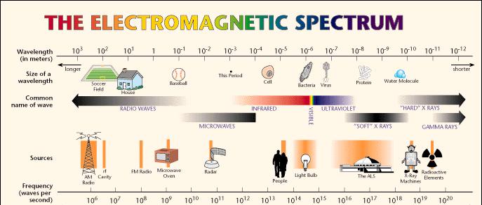
9 Radar Frequencies
10 Radar Frequency Bands Wavelength 1 km 1 m 1 mm 1 µm 1 nm Frequency 1 MHz 1 GHz 10 9 Hz Hz IR UV Visible VHF UHF L-Band S-Band C-Band X-Band Ku K Ka W Allocated Frequency (GHz) Wavelength (cm)
11 1.3 Airborne radar bands [1]
12 1.3.1 Airborne radar bands [1]
13 1.3.2 Airborne radar bands [1]

14 The Range Distance from the radar Measured from time delay between transmitted pulse and returned signal received
15 The Range Remember, in general v=d/t and d=vt The range is just a distance Since radio waves travel at the speed of light (v = c = 300,000 km/sec ) range = c time/2 Why divided by 2?
16 The Range The 2 is because the measured time is for a round trip to and from the target. To determine the range, you only want the time to the object, so you take half!


17 Radar Range Measurement Target Target range = cτ 2 where c = speed of light τ = round trip time
18 Radar The range and the direction of the target determine its location. This is the job for many radar applications such as air traffic control.
19 How Strong Is It? The strength of the received echo can also be measured This will vary with the distance of the target, its size, its shape and its composition
20 Types and Uses of Radar Search radars scan a large area with pulses of short radio waves Targeting radars use the same principle but scan a smaller area more often Navigational radars are like search radar, but use short waves that reflect off hard surfaces. They are used on commercial ships and long-distance commercial aircraft
21 Types and Uses of Radar Mapping radar scans a large regions for remote sensing and geography applications Wearable radar which is used to help the visually impaired as a substitute to eye. Air traffic control uses radar to reflect echoes off of aircraft Weather radar uses radar to reflect echoes off of clouds
22 Types and Uses of Radar Weather radars use radio waves with horizontal, dual (horizontal and vertical), or circular polarization Some weather radars use the Doppler effect to measure wind speeds
23 Incoherent Scatter Radar- A Radar Application Used to study the Earth's ionosphere and its interactions with the upper atmosphere, the magnetosphere, and the solar wind

24 Two Basic Types of Radar Continuous Wave Pulse Transmission

25 Continuous Wave Radar Employs continual RADAR transmission Separate transmit and receive antennas Relies on the DOPPLER SHIFT
26 Doppler Frequency Shifts Motion Away: Echo Frequency Decreases Motion Towards: Echo Frequency Increases
27 Continuous Wave Radar Components Transmitter CW RF Oscillator Antenna OUT Discriminator AMP Mixer IN Antenna Indicator
28 Pulsed radar A pulsed radar is characterized by a high power transmitter that generates an endless sequence of pulses. The rate at which the pulses are repeated is defined as the pulse repetition frequency. Parameters: pulse width, τ, pulse repetition frequency, PRF pulse period, T p = 1/PRF, usually in usually expressed in µsec PRF, usually in khz usually in µsec
29 Pulse Transmission
30 Pulse Width (PW) Pulse Transmission Length or duration of a given pulse Pulse Repetition Time (PRT=1/PRF) PRT is time from beginning of one pulse to the beginning of the next PRF is frequency at which consecutive pulses are transmitted. PW can determine the radar s minimum detection range; PW can determine the radar s maximum detection range. PRF can determine the radar s maximum detection range.
31 Pulse repetition frequency (PRF) a. Pulses per second b. Relation to pulse repetition time (PRT) c. Effects of varying PRF (1) Maximum range (2) Accuracy Peak power a. Maximum signal power of any pulse b. Affects maximum range of radar
32 Average power a. Total power transmitted per unit of time b. Relationship of average power to PW and PRT Duty cycle a. Ratio PW (time transmitting) to PRT (time of entire cycle, time transmitting plus rest time) b. Also equal to ratio of average power to peak power
33 Range vs. Power/PW/PRF Minimum Range: If still transmitting when return received RETURN NOT SEEN. Max Range: AveragePower PeakPower = PW PRT = PW * PRF As min Rh max Rh PW PRF
34 Describe the components of a pulse radar system. 1. Synchronizer 2. Transmitter 3. Antenna 4. Duplexer 5. Receiver 6. Display unit 7. Power supply
35 Pulse Radar Block Diagram Synchronizer Transmitter RF ATR Power Supply Duplexer (Switching Unit) Echo TR Antenna Display Video Receiver Antenna Bearing or Elevation
36 Pulsed radar architecture [1]
37 A lab-based based pulsed radar [4]
38 Pulsed modulation [1]
39 Pulsed Radar Bandwidth In the frequency domain, the transmitted and received signals are composed of spectral components centered on the radar operating frequency, f0, with a sin(x)/x shape. The practical limits of the frequency response is f0 ± 1/τ, and therefore the bandwidth of the receiver must be at least: BWRx 2/τ
40 Pulsed radar average power Since a pulsed radar only transmits for a small portion of the time, the average power of the radar is quite low: P av = P peak τ / T p For example a pulsed radar with a 1 µsec pulse width and a medium PRF of 4 khz that transmits at a peak power of 10kW transmits an average power of: P av = (10000 W) ( sec) (4000 /sec) = W = dbw
41 Pulsed radar range resolution The range resolution of a radar is its ability to distinguish two closely spaced targets along the same line of sight (LOS). The range resolution is a function of the pulse length, where pulse length, L p = cτ. For example, a 1 µsec pulse width yields a pulse length of 0.3 km. Two targets can be resolved in range if: L p < 2(R 2 R 1 )
42 Pulsed radar range resolution [4]
43 Pulsed radar range resolution [4]
44 Pulsed radar range ambiguity The PRF is another key radar parameter and is arguably one of the most difficult design decisions. The range of a target becomes ambiguous as a function of half the pulse period; in other words targets that are further than half the pulse period yield ambiguous range results. R amb = c / (2 PRF) = ct p / 2
45 4.4 Pulsed radar range ambiguity [1]
46 Range ambiguity R amb return time A target whose range is: PRF R < R amb = c / (2 PRF) = ct p /
47 Range ambiguity R amb return time PRF A target whose range is : R > R amb = c / (2 PRF) = ct p /
48 Range ambiguity R amb Which target is which? PRF?
49 Angle resolution [4]
50 Pulse Vs. Continuous Wave Pulse Echo Single Antenna Gives Range, usually Alt. as well Susceptible To Jamming Physical Range Determined By PW and PRF. Continuous Wave Requires 2 Antennae Range or Alt. Info High SNR More Difficult to Jam But Easily Deceived Amp can be tuned to look for expected frequencies
51 RADAR Wave Modulation Amplitude Modulation Vary the amplitude of the carrier sine wave Frequency Modulation Vary the frequency of the carrier sine wave Pulse-Amplitude Modulation Vary the amplitude of the pulses Pulse-Frequency Modulation Vary the Frequency at which the pulses occur
52 Modulation
53 Antennae Two Basic Purposes: Radiates RF Energy Provides Beam Forming and Focus Must Be 1/2 of the Wave Length for the maximum wave length employed Wide Beam pattern for Search, Narrow for Track
54 Beamwidth Vs. Accuracy Beamwidth vs Accuracy Ship A Ship B
55 Azimuth Angular Measurement Azimuth Angular Measurement Relative Bearing = Angle from ship s heading. True Bearing = Ship s Heading + Relative Bearing N Ship s Heading Angle Target Angle
56 Determining Altitude Determining Altitude Slant Range Altitude Angle of Elevation Altitude = slant range x sin0 elevation
57 Concentrating Radar Energy Through Beam Formation Linear Arrays Uses the Principle of wave summation (constructive interference) in a special direction and wave cancellation (destructive interference) in other directions. Made up of two or more simple half-wave antennas. Quasi-optical Uses reflectors and lenses to shape the beam.
58 Broadside Endfire Array
59 Reflector Shape Paraboloid - Conical Scan used for fire control - can be CW or Pulse Orange Peel Paraboliod - Usually CW and primarily for fire control Parabolic Cylinder - Wide search beam - generally larger and used for long-range search applications - Pulse
60 Wave Shaping -Quasi-Optical Systems Reflectors Lenses

61 Parabolic (dish) antenna Early airborne radars typically consisted of parabolic reflectors with horn feeds. The dish effectively directs the transmitted energy towards a target while at the same time gathering and concentrating some fraction of the returned energy.

62 Planar (phased) array antenna Recent radars more likely employ a planar array It is electronically steerable as a transmit or receive antenna using phase shifters. It has the further advantage of being capable of being integrated with the skin of the aircraft ( smart skin ).
63 Radar antenna beam patterns The main lobe of the radar antenna beam is central to the performance of the system. The side lobes are not only wasteful, they provide electronic warfare vulnerabilities.
64 Airborne radar modes Airborne radars are designed for and used in many different modes. Common modes include: air-to-air search air-to-air tracking air-to-air track-while-scan (TWS) ground mapping continuous wave (CW) illumination multimode
65 Air-to-air search [1]
66 Air-to-air tracking [1]
67 Air-to-air track-while-scan [1]
68 Ground mapping [1]
69 Continuous wave illumination
70 Multimode [1]

71 In-class exercises
72 Quick response exercise Given a 10.5 GHz intercept radar and a transmitter capable of providing a peak power of 44 dbw at a PRF of 2 khz: What pulse width yields an average power of 50W? What is the bandwidth in MHz and in % of this signal?
73 Pulsed radar calculations Design the pulse parameters so as to achieve maximum average power for an unspecified Ku band pulsed radar given the following component specifications and system requirements: the receiver has a bandwidth of at least 0.5% across the band the required range resolution is 50m The required range ambiguity is 25 km For cooling purposes, ensure that the duty cycle of the transmitter does not exceed 0.2%
74 References 1) Moir & Seabridge, Military Avionics Systems,, American Institute of Aeronautics & Astronautics, [Sections 2.6 & 2.7] 2) David Adamy, EW101 - A First Course in Electronic Warfare,, Artech House, [Chapters 3,4 & 6] 3) George W. Stimson, Introduction to Airborne Radar,, Second Edition, SciTch Publishing, ) Principles of Radar Systems,, student laboratory manual, , Lab-Volt (Quebec) Ltd, ) Mark A. Hicks, "Clip art licensed from the Clip Art Gallery on DiscoverySchool.com"
Radar Reprinted from "Waves in Motion", McGourty and Rideout, RET 2005
 Radar Reprinted from "Waves in Motion", McGourty and Rideout, RET 2005 What is Radar? RADAR (Radio Detection And Ranging) is a way to detect and study far off targets by transmitting a radio pulse in the
1. Basic radar range equation 2. Developing the radar range equation 3. Design impacts 4. Receiver sensitivity 5. Radar cross-section 6.
 Radar The radar range equation Prof. N.V.S.N. Sarma 1 Outline 1. Basic radar range equation. Developing the radar range equation 3. Design impacts 4. Receiver sensitivity 5. Radar cross-section 6. Low
RADAR DEVELOPMENT BASIC CONCEPT OF RADAR WAS DEMONSTRATED BY HEINRICH. HERTZ VERIFIED THE MAXWELL RADAR.
 1 RADAR WHAT IS RADAR? RADAR (RADIO DETECTION AND RANGING) IS A WAY TO DETECT AND STUDY FAR OFF TARGETS BY TRANSMITTING A RADIO PULSE IN THE DIRECTION OF THE TARGET AND OBSERVING THE REFLECTION OF THE
Lecture 1 INTRODUCTION. Dr. Aamer Iqbal Bhatti. Radar Signal Processing 1. Dr. Aamer Iqbal Bhatti
 Lecture 1 INTRODUCTION 1 Radar Introduction. A brief history. Simplified Radar Block Diagram. Two basic Radar Types. Radar Wave Modulation. 2 RADAR The term radar is an acronym for the phrase RAdio Detection
Microwave Remote Sensing (1)
") Microwave Remote Sensing (1) Microwave sensing encompasses both active and passive forms of remote sensing. The microwave portion of the spectrum covers the range from approximately 1cm to 1m in wavelength.
Microwave Remote Sensing (1) Microwave sensing encompasses both active and passive forms of remote sensing. The microwave portion of the spectrum covers the range from approximately 1cm to 1m in wavelength.
RADAR CHAPTER 3 RADAR
 RADAR CHAPTER 3 RADAR RDF becomes Radar 1. As World War II approached, scientists and the military were keen to find a method of detecting aircraft outside the normal range of eyes and ears. They found
RECOMMENDATION ITU-R S.1340 *,**
 Rec. ITU-R S.1340 1 RECOMMENDATION ITU-R S.1340 *,** Sharing between feeder links the mobile-satellite service and the aeronautical radionavigation service in the Earth-to-space direction in the band 15.4-15.7
Set No.1. Code No: R
 Set No.1 IV B.Tech. I Semester Regular Examinations, November -2008 RADAR SYSTEMS ( Common to Electronics & Communication Engineering and Electronics & Telematics) Time: 3 hours Max Marks: 80 Answer any
Fundamental Concepts of Radar
 Fundamental Concepts of Radar Dr Clive Alabaster & Dr Evan Hughes White Horse Radar Limited Contents Basic concepts of radar Detection Performance Target parameters measurable by a radar Primary/secondary
EE Chapter 14 Communication and Navigation Systems
 EE 2145230 Chapter 14 Communication and Navigation Systems Two way radio communication with air traffic controllers and tower operators is necessary. Aviation electronics or avionics: Avionic systems cover
Lecture 3 SIGNAL PROCESSING
 Lecture 3 SIGNAL PROCESSING Pulse Width t Pulse Train Spectrum of Pulse Train Spacing between Spectral Lines =PRF -1/t 1/t -PRF/2 PRF/2 Maximum Doppler shift giving unambiguous results should be with in
ATS 351 Lecture 9 Radar
 ATS 351 Lecture 9 Radar Radio Waves Electromagnetic Waves Consist of an electric field and a magnetic field Polarization: describes the orientation of the electric field. 1 Remote Sensing Passive vs Active
RECOMMENDATION ITU-R SA.1624 *
 Rec. ITU-R SA.1624 1 RECOMMENDATION ITU-R SA.1624 * Sharing between the Earth exploration-satellite (passive) and airborne altimeters in the aeronautical radionavigation service in the band 4 200-4 400
AIRCRAFT AVIONIC SYSTEMS
 AIRCRAFT AVIONIC SYSTEMS B-777 cockpit Package C:\Documents and ettings\administrato Course Outline Radio wave propagation Aircraft Navigation Systems - Very High Omni-range (VOR) system - Instrument Landing
Characteristics and protection criteria for radars operating in the aeronautical radionavigation service in the frequency band
 Recommendation ITU-R M.2008 (03/2012) Characteristics and protection criteria for radars operating in the aeronautical radionavigation service in the frequency band 13.25-13.40 GHz M Series Mobile, radiodetermination,
Introduction to Radar Systems. Radar Antennas. MIT Lincoln Laboratory. Radar Antennas - 1 PRH 6/18/02
 Introduction to Radar Systems Radar Antennas Radar Antennas - 1 Disclaimer of Endorsement and Liability The video courseware and accompanying viewgraphs presented on this server were prepared as an account
Introduction to: Radio Navigational Aids
 Introduction to: Radio Navigational Aids 1 Lecture Topics Basic Principles Radio Directional Finding (RDF) Radio Beacons Distance Measuring Equipment (DME) Instrument Landing System (ILS) Microwave Landing
A bluffer s guide to Radar
 A bluffer s guide to Radar Andy French December 2009 We may produce at will, from a sending station, an electrical effect in any particular region of the globe; (with which) we may determine the relative
RECOMMENDATION ITU-R S.1341*
 Rec. ITU-R S.1341 1 RECOMMENDATION ITU-R S.1341* SHARING BETWEEN FEEDER LINKS FOR THE MOBILE-SATELLITE SERVICE AND THE AERONAUTICAL RADIONAVIGATION SERVICE IN THE SPACE-TO-EARTH DIRECTION IN THE BAND 15.4-15.7
Exercise 1-3. Radar Antennas EXERCISE OBJECTIVE DISCUSSION OUTLINE DISCUSSION OF FUNDAMENTALS. Antenna types
 Exercise 1-3 Radar Antennas EXERCISE OBJECTIVE When you have completed this exercise, you will be familiar with the role of the antenna in a radar system. You will also be familiar with the intrinsic characteristics
Remote Sensing. Ch. 3 Microwaves (Part 1 of 2)
") Remote Sensing Ch. 3 Microwaves (Part 1 of 2) 3.1 Introduction 3.2 Radar Basics 3.3 Viewing Geometry and Spatial Resolution 3.4 Radar Image Distortions 3.1 Introduction Microwave (1cm to 1m in wavelength)
Remote Sensing Ch. 3 Microwaves (Part 1 of 2) 3.1 Introduction 3.2 Radar Basics 3.3 Viewing Geometry and Spatial Resolution 3.4 Radar Image Distortions 3.1 Introduction Microwave (1cm to 1m in wavelength)
Acknowledgment. Process of Atmospheric Radiation. Atmospheric Transmittance. Microwaves used by Radar GMAT Principles of Remote Sensing
 GMAT 9600 Principles of Remote Sensing Week 4 Radar Background & Surface Interactions Acknowledgment Mike Chang Natural Resources Canada Process of Atmospheric Radiation Dr. Linlin Ge and Prof Bruce Forster
INTRODUCTION TO RADAR SIGNAL PROCESSING
 INTRODUCTION TO RADAR SIGNAL PROCESSING Christos Ilioudis University of Strathclyde c.ilioudis@strath.ac.uk Overview History of Radar Basic Principles Principles of Measurements Coherent and Doppler Processing
RECOMMENDATION ITU-R SA (Question ITU-R 210/7)
") Rec. ITU-R SA.1016 1 RECOMMENDATION ITU-R SA.1016 SHARING CONSIDERATIONS RELATING TO DEEP-SPACE RESEARCH (Question ITU-R 210/7) Rec. ITU-R SA.1016 (1994) The ITU Radiocommunication Assembly, considering
Rec. ITU-R SA.1016 1 RECOMMENDATION ITU-R SA.1016 SHARING CONSIDERATIONS RELATING TO DEEP-SPACE RESEARCH (Question ITU-R 210/7) Rec. ITU-R SA.1016 (1994) The ITU Radiocommunication Assembly, considering
ANTENNA INTRODUCTION / BASICS
 ANTENNA INTRODUCTION / BASICS RULES OF THUMB: 1. The Gain of an antenna with losses is given by: 2. Gain of rectangular X-Band Aperture G = 1.4 LW L = length of aperture in cm Where: W = width of aperture
SECTION 2 BROADBAND RF CHARACTERISTICS. 2.1 Frequency bands
 SECTION 2 BROADBAND RF CHARACTERISTICS 2.1 Frequency bands 2.1.1 Use of AMS(R)S bands Note.- Categories of messages, and their relative priorities within the aeronautical mobile (R) service, are given
Exercise 1-5. Antennas in EW: Sidelobe Jamming and Space Discrimination EXERCISE OBJECTIVE
 Exercise 1-5 Antennas in EW: Sidelobe Jamming EXERCISE OBJECTIVE To demonstrate that noise jamming can be injected into a radar receiver via the sidelobes of the radar antenna. To outline the effects of
Boost Your Skills with On-Site Courses Tailored to Your Needs
 Boost Your Skills with On-Site Courses Tailored to Your Needs www.aticourses.com The Applied Technology Institute specializes in training programs for technical professionals. Our courses keep you current
AGF-216. The Earth s Ionosphere & Radars on Svalbard
 AGF-216 The Earth s Ionosphere & Radars on Svalbard Katie Herlingshaw 07/02/2018 1 Overview Radar basics what, how, where, why? How do we use radars on Svalbard? What is EISCAT and what does it measure?
E-716-A Mobile Communications Systems. Lecture #2 Basic Concepts of Wireless Transmission (p1) Instructor: Dr. Ahmad El-Banna
 Instructor: Dr. Ahmad El-Banna") October 2014 Ahmad El-Banna Integrated Technical Education Cluster At AlAmeeria E-716-A Mobile Communications Systems Lecture #2 Basic Concepts of Wireless Transmission (p1) Instructor: Dr. Ahmad El-Banna
October 2014 Ahmad El-Banna Integrated Technical Education Cluster At AlAmeeria E-716-A Mobile Communications Systems Lecture #2 Basic Concepts of Wireless Transmission (p1) Instructor: Dr. Ahmad El-Banna
REPORT ITU-R M Interference and noise problems for maritime mobile-satellite systems using frequencies in the region of 1.5 and 1.
 Rep. ITU-R M.764-3 1 REPORT ITU-R M.764-3 Interference and noise problems for maritime mobile-satellite systems using frequencies in the region of 1.5 and 1.6 GHz (1978-1982-1986-2005) 1 Introduction Operational
ECE 583 Lectures 15 RADAR History and Basics
 ECE 583 Lectures 15 RADAR History and Basics 1 -RADAR - A BIT OF HISTORY The acronym - RADAR is an acronym for Radio Detection and Ranging The Start: The thought/concept of using propagating EM waves began
Space Frequency Coordination Group
 Space Frequency Coordination Group Report SFCG 38-1 POTENTIAL RFI TO EESS (ACTIVE) CLOUD PROFILE RADARS IN 94.0-94.1 GHZ FREQUENCY BAND FROM OTHER SERVICES Abstract This new SFCG report analyzes potential
Know how Pulsed Doppler radar works and how it s able to determine target velocity. Know how the Moving Target Indicator (MTI) determines target
 determines target") Moving Target Indicator 1 Objectives Know how Pulsed Doppler radar works and how it s able to determine target velocity. Know how the Moving Target Indicator (MTI) determines target velocity. Be able to
Moving Target Indicator 1 Objectives Know how Pulsed Doppler radar works and how it s able to determine target velocity. Know how the Moving Target Indicator (MTI) determines target velocity. Be able to
ANTENNA INTRODUCTION / BASICS
 Rules of Thumb: 1. The Gain of an antenna with losses is given by: G 0A 8 Where 0 ' Efficiency A ' Physical aperture area 8 ' wavelength ANTENNA INTRODUCTION / BASICS another is:. Gain of rectangular X-Band
INTRODUCTION. Basic operating principle Tracking radars Techniques of target detection Examples of monopulse radar systems
 Tracking Radar H.P INTRODUCTION Basic operating principle Tracking radars Techniques of target detection Examples of monopulse radar systems 2 RADAR FUNCTIONS NORMAL RADAR FUNCTIONS 1. Range (from pulse
Basic Radar Definitions Introduction p. 1 Basic relations p. 1 The radar equation p. 4 Transmitter power p. 9 Other forms of radar equation p.
 Basic Radar Definitions Basic relations p. 1 The radar equation p. 4 Transmitter power p. 9 Other forms of radar equation p. 11 Decibel representation of the radar equation p. 13 Radar frequencies p. 15
Introduction to Radar Systems. The Radar Equation. MIT Lincoln Laboratory _P_1Y.ppt ODonnell
 Introduction to Radar Systems The Radar Equation 361564_P_1Y.ppt Disclaimer of Endorsement and Liability The video courseware and accompanying viewgraphs presented on this server were prepared as an account
Optical Delay Line Application Note
 1 Optical Delay Line Application Note 1.1 General Optical delay lines system (ODL), incorporates a high performance lasers such as DFBs, optical modulators for high operation frequencies, photodiodes,
Radar. Seminar report. Submitted in partial fulfillment of the requirement for the award of degree Of Mechanical
 A Seminar report on Radar Submitted in partial fulfillment of the requirement for the award of degree Of Mechanical SUBMITTED TO: SUBMITTED BY: www.studymafia.org www.studymafia.org Preface I have made
The Discussion of this exercise covers the following points:
 Exercise 3-2 Frequency-Modulated CW Radar EXERCISE OBJECTIVE When you have completed this exercise, you will be familiar with FM ranging using frequency-modulated continuous-wave (FM-CW) radar. DISCUSSION
NEETS MODULE 18-Radar Principles UNCLASSIFIED
 1 RADAR FUNDAMENTALS LEARNING OBJECTIVES After you finish this chapter, you should be able to do the following: 1. Define range, bearing, and altitude as they relate to a radar system. 2. Discuss how pulse
ESCI Cloud Physics and Precipitation Processes Lesson 10 - Weather Radar Dr. DeCaria
 ESCI 340 - Cloud Physics and Precipitation Processes Lesson 10 - Weather Radar Dr. DeCaria References: A Short Course in Cloud Physics, 3rd ed., Rogers and Yau, Ch. 11 Radar Principles The components of
Lecture 9. Radar Equation. Dr. Aamer Iqbal. Radar Signal Processing Dr. Aamer Iqbal Bhatti
 Lecture 9 Radar Equation Dr. Aamer Iqbal 1 ystem Losses: Losses within the radar system itself are from many sources. everal are described below. L PL =the plumbing loss. L PO =the polarization loss. L
Microwave Remote Sensing
 Provide copy on a CD of the UCAR multi-media tutorial to all in class. Assign Ch-7 and Ch-9 (for two weeks) as reading material for this class. HW#4 (Due in two weeks) Problems 1,2,3 and 4 (Chapter 7)
Scalable Front-End Digital Signal Processing for a Phased Array Radar Demonstrator. International Radar Symposium 2012 Warsaw, 24 May 2012
 Scalable Front-End Digital Signal Processing for a Phased Array Radar Demonstrator F. Winterstein, G. Sessler, M. Montagna, M. Mendijur, G. Dauron, PM. Besso International Radar Symposium 2012 Warsaw,
RECOMMENDATION ITU-R SA.1628
 Rec. ITU-R SA.628 RECOMMENDATION ITU-R SA.628 Feasibility of sharing in the band 35.5-36 GHZ between the Earth exploration-satellite service (active) and space research service (active), and other services
Aviation Electricity and Electronics Radar
 NONRESIDENT TRAINING COURSE Aviation Electricity and Electronics Radar NAVEDTRA 4339 DISTRIBUTION STATEMENT A: Approved for public release; distribution is unlimited. PREFACE About this course: This is
Rec. ITU-R P RECOMMENDATION ITU-R P *
 Rec. ITU-R P.682-1 1 RECOMMENDATION ITU-R P.682-1 * PROPAGATION DATA REQUIRED FOR THE DESIGN OF EARTH-SPACE AERONAUTICAL MOBILE TELECOMMUNICATION SYSTEMS (Question ITU-R 207/3) Rec. 682-1 (1990-1992) The
Frequency Agility and Barrage Noise Jamming
 Exercise 1-3 Frequency Agility and Barrage Noise Jamming EXERCISE OBJECTIVE To demonstrate frequency agility, a radar electronic protection is used against spot noise jamming. To justify the use of barrage
2B.6 SALIENT FEATURES OF THE CSU-CHILL RADAR X-BAND CHANNEL UPGRADE
 2B.6 SALIENT FEATURES OF THE CSU-CHILL RADAR X-BAND CHANNEL UPGRADE Francesc Junyent* and V. Chandrasekar, P. Kennedy, S. Rutledge, V. Bringi, J. George, and D. Brunkow Colorado State University, Fort
ESA Radar Remote Sensing Course ESA Radar Remote Sensing Course Radar, SAR, InSAR; a first introduction
 Radar, SAR, InSAR; a first introduction Ramon Hanssen Delft University of Technology The Netherlands r.f.hanssen@tudelft.nl Charles University in Prague Contents Radar background and fundamentals Imaging
Mesoscale Atmospheric Systems. Radar meteorology (part 1) 04 March 2014 Heini Wernli. with a lot of input from Marc Wüest
 04 March 2014 Heini Wernli. with a lot of input from Marc Wüest") Mesoscale Atmospheric Systems Radar meteorology (part 1) 04 March 2014 Heini Wernli with a lot of input from Marc Wüest An example radar picture What are the axes? What is the resolution? What are the
Mesoscale Atmospheric Systems Radar meteorology (part 1) 04 March 2014 Heini Wernli with a lot of input from Marc Wüest An example radar picture What are the axes? What is the resolution? What are the
DIGITAL BEAM-FORMING ANTENNA OPTIMIZATION FOR REFLECTOR BASED SPACE DEBRIS RADAR SYSTEM
 DIGITAL BEAM-FORMING ANTENNA OPTIMIZATION FOR REFLECTOR BASED SPACE DEBRIS RADAR SYSTEM A. Patyuchenko, M. Younis, G. Krieger German Aerospace Center (DLR), Microwaves and Radar Institute, Muenchner Strasse
Wave Sensing Radar and Wave Reconstruction
 Applied Physical Sciences Corp. 475 Bridge Street, Suite 100, Groton, CT 06340 (860) 448-3253 www.aphysci.com Wave Sensing Radar and Wave Reconstruction Gordon Farquharson, John Mower, and Bill Plant (APL-UW)
Amateur Radio License. Propagation and Antennas
 Amateur Radio License Propagation and Antennas Todays Topics Propagation Antennas Propagation Modes Ground wave Low HF and below, ground acts as waveguide Line-of-Sight (LOS) VHF and above, radio waves
Modern radio techniques
 Modern radio techniques for probing the ionosphere Receiver, radar, advanced ionospheric sounder, and related techniques Cesidio Bianchi INGV - Roma Italy Ionospheric properties related to radio waves
DOPPLER RADAR. Doppler Velocities - The Doppler shift. if φ 0 = 0, then φ = 4π. where
 Q: How does the radar get velocity information on the particles? DOPPLER RADAR Doppler Velocities - The Doppler shift Simple Example: Measures a Doppler shift - change in frequency of radiation due to
AIR ROUTE SURVEILLANCE 3D RADAR
 AIR TRAFFIC MANAGEMENT AIR ROUTE SURVEILLANCE 3D RADAR Supplying ATM systems around the world for more than 30 years indracompany.com ARSR-10D3 AIR ROUTE SURVEILLANCE 3D RADAR ARSR 3D & MSSR Antenna Medium
CHAPTER 1 INTRODUCTION
 1 CHAPTER 1 INTRODUCTION In maritime surveillance, radar echoes which clutter the radar and challenge small target detection. Clutter is unwanted echoes that can make target detection of wanted targets
Exercise 3-3. Multiple-Source Jamming Techniques EXERCISE OBJECTIVE
 Exercise 3-3 Multiple-Source Jamming Techniques EXERCISE OBJECTIVE To introduce multiple-source jamming techniques. To differentiate between incoherent multiple-source jamming (cooperative jamming), and
Potential interference from spaceborne active sensors into radionavigation-satellite service receivers in the MHz band
 Rec. ITU-R RS.1347 1 RECOMMENDATION ITU-R RS.1347* Rec. ITU-R RS.1347 FEASIBILITY OF SHARING BETWEEN RADIONAVIGATION-SATELLITE SERVICE RECEIVERS AND THE EARTH EXPLORATION-SATELLITE (ACTIVE) AND SPACE RESEARCH
Section 1 Wireless Transmission
 Part : Wireless Communication! section : Wireless Transmission! Section : Digital modulation! Section : Multiplexing/Medium Access Control (MAC) Section Wireless Transmission Intro. to Wireless Transmission
To design Phase Shifter. To design bias circuit for the Phase Shifter. Realization and test of both circuits (Doppler Simulator) with
 with") Prof. Dr. Eng. Klaus Solbach Department of High Frequency Techniques University of Duisburg-Essen, Germany Presented by Muhammad Ali Ashraf Muhammad Ali Ashraf 2226956 Outline 1. Motivation 2. Phase Shifters
Prof. Dr. Eng. Klaus Solbach Department of High Frequency Techniques University of Duisburg-Essen, Germany Presented by Muhammad Ali Ashraf Muhammad Ali Ashraf 2226956 Outline 1. Motivation 2. Phase Shifters
LE/ESSE Payload Design
 LE/ESSE4360 - Payload Design 3.4 Spacecraft Sensors - Radar Sensors Earth, Moon, Mars, and Beyond Dr. Jinjun Shan, Professor of Space Engineering Department of Earth and Space Science and Engineering Room
Dartmouth College SuperDARN Radars
 Dartmouth College SuperDARN Radars Under the guidance of Thayer School professor Simon Shepherd, a pair of backscatter radars were constructed in the desert of central Oregon over the Summer and Fall of
Introduction to Radar Systems
 Introduction to Radar Systems Dr. Robert M. O Donnell Introduction-1 Disclaimer of Endorsement and Liability The video courseware and accompanying viewgraphs presented on this server were prepared as an
Lecture Topics. Doppler CW Radar System, FM-CW Radar System, Moving Target Indication Radar System, and Pulsed Doppler Radar System
 Lecture Topics Doppler CW Radar System, FM-CW Radar System, Moving Target Indication Radar System, and Pulsed Doppler Radar System 1 Remember that: An EM wave is a function of both space and time e.g.
Dr. John S. Seybold. November 9, IEEE Melbourne COM/SP AP/MTT Chapters
 Antennas Dr. John S. Seybold November 9, 004 IEEE Melbourne COM/SP AP/MTT Chapters Introduction The antenna is the air interface of a communication system An antenna is an electrical conductor or system
Satellite Signals and Communications Principles. Dr. Ugur GUVEN Aerospace Engineer (P.hD)
") Satellite Signals and Communications Principles Dr. Ugur GUVEN Aerospace Engineer (P.hD) Principle of Satellite Signals In essence, satellite signals are electromagnetic waves that travel from the satellite
Satellite Signals and Communications Principles Dr. Ugur GUVEN Aerospace Engineer (P.hD) Principle of Satellite Signals In essence, satellite signals are electromagnetic waves that travel from the satellite
Electronic Scanning Antennas Product Information
 MICROWAVE APPLICATIONS GROUP Electronic Scanning Antennas Product Information (MAG) has a proven record of creativity and innovation in microwave component and subsystem design for government, military,
THE NATURE OF GROUND CLUTTER AFFECTING RADAR PERFORMANCE MOHAMMED J. AL SUMIADAEE
 International Journal of Electronics, Communication & Instrumentation Engineering Research and Development (IJECIERD) ISSN(P): 2249-684X; ISSN(E): 2249-7951 Vol. 6, Issue 2, Apr 2016, 7-14 TJPRC Pvt. Ltd.
KULLIYYAH OF ENGINEERING
 KULLIYYAH OF ENGINEERING DEPARTMENT OF ELECTRICAL & COMPUTER ENGINEERING ANTENNA AND WAVE PROPAGATION LABORATORY (ECE 4103) EXPERIMENT NO 3 RADIATION PATTERN AND GAIN CHARACTERISTICS OF THE DISH (PARABOLIC)
SODAR- sonic detecting and ranging
 Active Remote Sensing of the PBL Immersed vs. remote sensors Active vs. passive sensors RADAR- radio detection and ranging WSR-88D TDWR wind profiler SODAR- sonic detecting and ranging minisodar RASS RADAR
Vehicle Networks. Wireless communication basics. Univ.-Prof. Dr. Thomas Strang, Dipl.-Inform. Matthias Röckl
 Vehicle Networks Wireless communication basics Univ.-Prof. Dr. Thomas Strang, Dipl.-Inform. Matthias Röckl Outline Wireless Signal Propagation Electro-magnetic waves Signal impairments Attenuation Distortion
Chapter 1 Introduction
 Wireless Information Transmission System Lab. Chapter 1 Introduction National Sun Yat-sen University Table of Contents Elements of a Digital Communication System Communication Channels and Their Wire-line
O T & E for ESM Systems and the use of simulation for system performance clarification
 O T & E for ESM Systems and the use of simulation for system performance clarification Dr. Sue Robertson EW Defence Limited United Kingdom e-mail: sue@ewdefence.co.uk Tuesday 11 March 2014 EW Defence Limited
High Resolution W-Band Radar Detection and Characterization of Aircraft Wake Vortices in Precipitation. Thomas A. Seliga and James B.
 High Resolution W-Band Radar Detection and Characterization of Aircraft Wake Vortices in Precipitation Thomas A. Seliga and James B. Mead 4L 4R 4L/22R 4R/22L W-Band Radar Site The W-Band Radar System
Amateur Microwave Communications. Ray Perrin VE3FN, VY0AAA April 2010
 Amateur Microwave Communications Ray Perrin VE3FN, VY0AAA April 2010 Introduction Microwaves are the frequencies above 1000 MHz More than 99% of the radio amateur frequency allocation is in the microwave
1. Explain how Doppler direction is identified with FMCW radar. Fig Block diagram of FM-CW radar. f b (up) = f r - f d. f b (down) = f r + f d
 = f r - f d. f b (down) = f r + f d") 1. Explain how Doppler direction is identified with FMCW radar. A block diagram illustrating the principle of the FM-CW radar is shown in Fig. 4.1.1 A portion of the transmitter signal acts as the reference
1. Explain how Doppler direction is identified with FMCW radar. A block diagram illustrating the principle of the FM-CW radar is shown in Fig. 4.1.1 A portion of the transmitter signal acts as the reference
Using Frequency Diversity to Improve Measurement Speed Roger Dygert MI Technologies, 1125 Satellite Blvd., Suite 100 Suwanee, GA 30024
 Using Frequency Diversity to Improve Measurement Speed Roger Dygert MI Technologies, 1125 Satellite Blvd., Suite 1 Suwanee, GA 324 ABSTRACT Conventional antenna measurement systems use a multiplexer or
GET10B Radar Measurement Basics- Spectrum Analysis of Pulsed Signals. Copyright 2001 Agilent Technologies, Inc.
 GET10B Radar Measurement Basics- Spectrum Analysis of Pulsed Signals Copyright 2001 Agilent Technologies, Inc. Agenda: Power Measurements Module #1: Introduction Module #2: Power Measurements Module #3:
MOBILE RAPID-SCANNING X-BAND POLARIMETRIC (RaXPol) DOPPLER RADAR SYSTEM Andrew L. Pazmany 1 * and Howard B. Bluestein 2
 DOPPLER RADAR SYSTEM Andrew L. Pazmany 1 * and Howard B. Bluestein 2") 16B.2 MOBILE RAPID-SCANNING X-BAND POLARIMETRIC (RaXPol) DOPPLER RADAR SYSTEM Andrew L. Pazmany 1 * and Howard B. Bluestein 2 1 ProSensing Inc., Amherst, Massachusetts 2 University of Oklahoma, Norman,
16B.2 MOBILE RAPID-SCANNING X-BAND POLARIMETRIC (RaXPol) DOPPLER RADAR SYSTEM Andrew L. Pazmany 1 * and Howard B. Bluestein 2 1 ProSensing Inc., Amherst, Massachusetts 2 University of Oklahoma, Norman,
Adaptive SAR Results with the LiMIT Testbed
 Adaptive SAR Results with the LiMIT Testbed Gerald Benitz Adaptive Sensor Array Processing Workshop 7 June 2005 999999-1 Outline LiMIT collection platform SAR sidelobe recovery Electronic Protection (EP)
MAKING TRANSIENT ANTENNA MEASUREMENTS
 MAKING TRANSIENT ANTENNA MEASUREMENTS Roger Dygert, Steven R. Nichols MI Technologies, 1125 Satellite Boulevard, Suite 100 Suwanee, GA 30024-4629 ABSTRACT In addition to steady state performance, antennas
Exercise 1-4. The Radar Equation EXERCISE OBJECTIVE DISCUSSION OUTLINE DISCUSSION OF FUNDAMENTALS
 Exercise 1-4 The Radar Equation EXERCISE OBJECTIVE When you have completed this exercise, you will be familiar with the different parameters in the radar equation, and with the interaction between these
Receiver Signal to Noise Ratios for IPDA Lidars Using Sine-wave and Pulsed Laser Modulation and Direct Detections
 Receiver Signal to Noise Ratios for IPDA Lidars Using Sine-wave and Pulsed Laser Modulation and Direct Detections Xiaoli Sun and James B. Abshire NASA Goddard Space Flight Center Solar System Division,
Lecture Notes On COMMUNICATION SYSTEM ENGINEERING II
 Lecture Notes On COMMUNICATION SYSTEM ENGINEERING II (Radar Systems) Department of Electronics and Telecommunications VEER SURENDRA SAI UNIVERSITY OF TECHNOLOGY BURLA ODISHA-768018 1 COMMUNICATION SYSTEM
EISCAT Experiments. Anders Tjulin EISCAT Scientific Association 2nd March 2017
 EISCAT Experiments Anders Tjulin EISCAT Scientific Association 2nd March 2017 Contents 1 Introduction 3 2 Overview 3 2.1 The radar systems.......................... 3 2.2 Antenna scan patterns........................
Antenna Engineering Lecture 0: Introduction
 Antenna Engineering Lecture 0: Introduction ELC 405a Fall 2011 Department of Electronics and Communications Engineering Faculty of Engineering Cairo University 2 Outline 1 Why Study Antenna Engineering?
Radar Systems Engineering Lecture 12 Clutter Rejection
 Radar Systems Engineering Lecture 12 Clutter Rejection Part 1 - Basics and Moving Target Indication Dr. Robert M. O Donnell Guest Lecturer Radar Systems Course 1 Block Diagram of Radar System Transmitter
Multi-function Phased Array Radars (MPAR)
") Multi-function Phased Array Radars (MPAR) Satyanarayana S, General Manager - RF systems, Mistral Solutions Pvt. Ltd., Bangalore, Karnataka, satyanarayana.s@mistralsolutions.com Abstract In this paper,
Multi-function Phased Array Radars (MPAR) Satyanarayana S, General Manager - RF systems, Mistral Solutions Pvt. Ltd., Bangalore, Karnataka, satyanarayana.s@mistralsolutions.com Abstract In this paper,
10 Secondary Surveillance Radar
 10 Secondary Surveillance Radar As we have just noted, the primary radar element of the ATC Surveillance Radar System provides detection of suitable targets with good accuracy in bearing and range measurement
Fundamentals Of Commercial Doppler Systems
 Fundamentals Of Commercial Doppler Systems Speed, Motion and Distance Measurements I. Introduction MDT manufactures a large variety of microwave oscillators, transceivers, and other components for the
Principles of Pulse-Doppler Radar p. 1 Types of Doppler Radar p. 1 Definitions p. 5 Doppler Shift p. 5 Translation to Zero Intermediate Frequency p.
 Preface p. xv Principles of Pulse-Doppler Radar p. 1 Types of Doppler Radar p. 1 Definitions p. 5 Doppler Shift p. 5 Translation to Zero Intermediate Frequency p. 6 Doppler Ambiguities and Blind Speeds
Antenna pattern. Figure 1: Antenna Gain as a function of Angle. Modulated Transmitter Antenna Modulated Transmission Target
 ANGLE TRACKING Amplitude Measurement Amplitude threshold is used to determine that a target is within the beam This gives a very rough measure of the target direction (within one beamwidth) if the target
WIRELESS TRANSMISSION
 COMP 635: WIRELESS NETWORKS WIRELESS TRANSMISSION Jasleen Kaur Fall 205 Outline Frequenc Spectrum Ø Usage and Licensing Signals and Antennas Ø Propagation Characteristics Multipleing Ø Space, Frequenc,
Mission Solution 300
 Mission Solution 300 Standard configuration for point defence Member of the Thales Mission Solution family Standard configuration of integrated sensors, effectors, CMS, communication system and navigation
MULTI-CHANNEL SAR EXPERIMENTS FROM THE SPACE AND FROM GROUND: POTENTIAL EVOLUTION OF PRESENT GENERATION SPACEBORNE SAR
 3 nd International Workshop on Science and Applications of SAR Polarimetry and Polarimetric Interferometry POLinSAR 2007 January 25, 2007 ESA/ESRIN Frascati, Italy MULTI-CHANNEL SAR EXPERIMENTS FROM THE
UNIT Derive the fundamental equation for free space propagation?
 UNIT 8 1. Derive the fundamental equation for free space propagation? Fundamental Equation for Free Space Propagation Consider the transmitter power (P t ) radiated uniformly in all the directions (isotropic),