Photonics & Electronics Photonics Detailed Study in VCE Physics
|
|
|
- Patrick Reeves
- 6 years ago
- Views:
Transcription


1 Assoc Prof Alex Mazzolini Assoc Dean (Learning and Teaching) Faculty of Engineering & Industrial Sciences Leader, Engineering and Science Education Research (ESER) group Co-author PHYSICS 12 (2 nd Ed) Heinemann Photonics & Electronics Photonics Detailed Study in VCE Physics

2 Communications using Optics & Photonics Optics/photonics can transmit information very efficiently, and it is the major enabling technology for current and future generations of telecommunications and information systems. 2
 technology, can carry over 1,000,000 conversations.")
3 Optical Fibres versus Copper Cables 600 twisted-pair copper cable carries 600 conversations 6 coaxial copper cable carries 2700 conversations One single optical fibre, with modern wavelength division multiplexing (WDM) technology, can carry over 1,000,000 conversations. Copper & FO cable 3


4 Optics/Photonics and other High Tech Industries Photonics technology also has important uses in the manufacturing industry the medical industry the civil engineering industry the entertainment industry the sustainability industry the transport industry Miniature mirror array used in data projectors Tsing Ma Bridge, Hong Kong Fibre optic stress sensors in structures Laser Eye Surgery Blu-ray DVDs use new generation blue light laser diodes Fly-by-wire control systems use optical fibre Australian manufactured solar energy collectors 4
")

5 Optics/Photonics and Low Tech Industries Lighting solutions for isolated communities in developing countries Light Up The World (LUTW) Development of an inexpensive, ultra-efficient, self-sustaining, ultrabright WLED* system *WLED is White LED High power WLED torches now commonly available 5
 to transmit info from one place to another. France had a network of 556 stations stretching a total distance of 4,800 km.")
6 Using Light for Communications Early examples: smoke signals, signal flags, signal fires, etc More resent and more organised examples: (a) Optical telegraph (1790 s Claude Chappe d Auteroche ) Used semaphores (either flags or lanterns) to transmit info from one place to another. France had a network of 556 stations stretching a total distance of 4,800 km. Replaced in mid to late 1800s by the electric telegraph 6
 Aldis lamps (1867) for naval communications Navy signal")

7 Using Light for Communications More recent and more organised examples: (b) Aldis lamps (1867) for naval communications Navy signal lamps show all the characteristic modules of modern fibre optic communication systems. (light source, modulation, transmission medium and detector) 7

 9V DC power supply c e Phototransistor Piezo buzzer Optical")
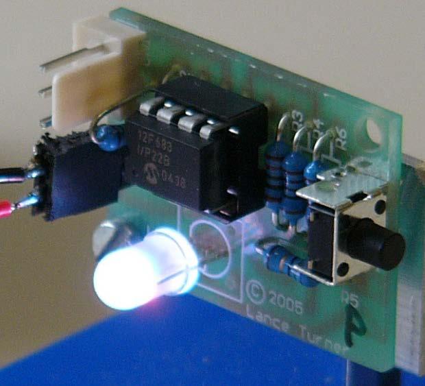
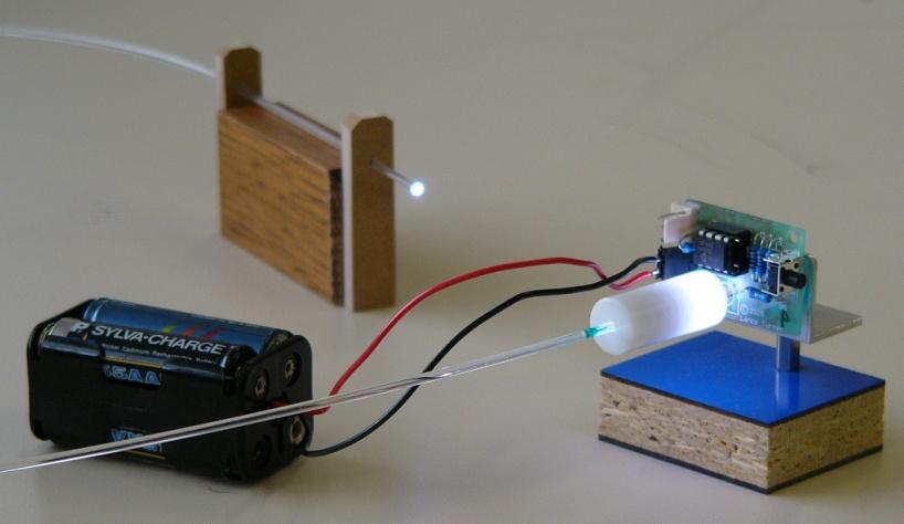
8 Optical Telegraph Use a LED transmitter and a PT receiver to send coded digital messages Optical telegraph is an example of a DIGITAL optical communications system Figure 5-1: Light Emitting Diode (LED) circuit (transmitter) 9V DC power supply LED K (-) R A (+) Figure 5-2: Phototransistor circuit (receiver) 9V DC power supply c e Phototransistor Piezo buzzer Optical telegraph 8


9 The photophone: A great idea but before its time In 1876, Alexander Graham Bell invented the telephone. In 1880, he invented the photophone. Photophone used sunlight modulated by a voice-driven diaphragm to transmit speech to a receiver over 200m away. 9
10 Intensity Modulation: Simple Photophone Photophone is an example of an ANALOG optical communications system 10
 modulation voltage from audio source (~200 mv)")
11 Build your own 21 st Century Photophone Transmitter external power supply ~3 V LD R (1 Ω) modulation voltage from audio source (~200 mv) 11
 V out Speaker Audio analog optical communications")
12 V cc Build your own 21 st Century Photophone Receiver 9 V C (1 µf) Audio Amp R (1 kω) V out Speaker Audio analog optical communications 12
13 Photophone: Technical Issues Fast modulation rate sufficient for good audio response. But idea lay dormant for a century due to problems with... transmission medium stability Moving obstructions (people, horses etc.) and fluctuations in atmospheric conditions (fog, rain dust, etc.) meant that the transmission medium was unpredictable over long distances light sources intense but not bright (1970: high purity optical fibres produced) light energy could not be channelled into a small forward solid angle (ie large divergence, and its intensity decreased according to the inverse square law (ie no good over long distances)) (1960: Laser invented) 13
 2006 (1B users) nearly 17% of the world population 2009 (1.7B users) or 26% of the world population 2012 (2.")
14 Internet Revolution & the Hunger for Bandwidth Internet started 1970 (5 hosts) 1977 (100 hosts) 1984 (1000 hosts) 1987 (10,000 hosts) 1989 (100,000 hosts) 2000 (100M hosts) 1992 (1M hosts) 2002 (200M hosts and 850M users) 2006 (1B users) nearly 17% of the world population 2009 (1.7B users) or 26% of the world population 2012 (2.5B users or 30% of the world population
 Will cost around $43 billion (over 8 years) to establish")
15 National Broadband Network National Broadband Network is a full fibre to the home network proposed for Australia. Will provide download speeds of around 100 megabits per second to 93% of Australian homes and businesses (ultra-fast wireless for other 7%) Will cost around $43 billion (over 8 years) to establish Major infrastructure investment in our information future Bigger than Snowy Mountains Hydro-Electric Scheme 15


 Education (eg video")

16 National Broadband Network A full fibre to the home NBN network makes a lot of sense, even though it may cost a lot of cents. Business & Commerce (access to national/international suppliers) Leisure and lifestyle (eg video on demand) Education (eg video conferencing) Medicine (eg on-line diagnosis) I want to buy a camera I want the specialist to advise me now I want to run a course on-line I want to see a movie 16
.")
17 Total Internal Reflection If the incident angle is greater than the critical angle, then none of the beam is transmitted and all of the beam is reflected (this is called total internal reflection or TIR). Perspex hemisphere 17

 With TIR, all light is fully reflected (none refracted) at each reflection and")
18 Why Optical Fibres: (a) Total Internal Reflection Without TIR, light is refracted at each reflection and intensity of channelled light quickly decreases (Many thousands of reflections per meter!!!) With TIR, all light is fully reflected (none refracted) at each reflection and intensity of channelled light remains constant Perspex Pretzel 18
 Unworkable transmission losses above 30 MHz")
19 Why Optical Fibres: (b) Bandwidth Bandwidth of twisted-pair solid copper cable limited by skin effect (Bandwidth decreases rapidly with increasing frequency) Unworkable transmission losses above 30 MHz 19
20 Optical Fibre Bandwidth Bandwidth: Optical fibres do not have skin effect Theoretical maximum carrier frequency is very high! Practical bandwidth limited by light source and detector characteristics. Currently ~ 500 GHz. But still orders of magnitude higher than coax cable (next best option). Theoretical max. bandwidth, for 1500 nm light f c = c/λ = 3x10 8 /1.5x10-6 = 200,000 GHz. 20


 Absorption by")
 wavelength Attenuation minimum is")
21 Why Optical Fibres: (c) Attenuation Rayleigh Scattering by inhomogeneities frozen into the glass structure itself Absorption by impurity ions and atoms of the pure glass (eg, OH- ion) Absorption by vibrating molecular bonds (eg Si - O) wavelength Attenuation minimum is around 0.2 db/km 21

 at the exit end of the fibre. Limits rate at which you can send info down the fibre (pulse overlap).")
22 Core has constant index of refraction (all rays have same velocity) Stepped-Index Multimode Fibre dispersion input output If narrow pulses spread out, we cannot have pulses Lowest order mode transits the fibre in the shortest time. too close together Highest order mode transits the fibre in the longest time or we have overlap (travel at the same velocity over a longer distance) So a narrow input pulse spreads out (in time) at the exit end of the fibre. Limits rate at which you can send info down the fibre (pulse overlap). Process called MODAL DISPERSION (typically around 100 ns per km) 22

23 Graded-Index Multimode Fibre Core has varying index of refraction (higher n and v near centre, lower n and v near periphery) less dispersion input output ALL modes transit the fibre in approximately the same time. Lowest order mode travels the shortest distance but at the slowest velocity. Highest order mode travels the longest distance but at the fastest velocity. Modal dispersion only about 1 ns per km Reduced pulse spread means we can have pulses closer together and hence more bandwidth 23
24 Core has small diameter so only lowest order mode can propagate (only 1 ray path possible) Single Mode Fibre No modal dispersion input output Only one path so minimal pulse spread, means we can have pulses very close together and hence much more bandwidth No more MODAL dispersion but still some (2 nd order) dispersions that cause pulse spreading 24
25 How Much Bandwidth is Currently Possible dispersion management (not just modal dispersion but other dispersions as well), wavelength-division multiplexing, optical amplifiers, modern-day optical fibres, light sources and detectors can now carry information at a few Terabits per second over 160 kilometres of fibre (2010 data) A Terabit = 1 x bits or 1,000,000,000,000 bits 25
26 Generating light - Photonic sources Require a highly controllable and efficient form of light production (beyond thermal sources such as sunlight, incandescent lamp, etc) light-emitting diodes (LEDs) semiconductor lasers ( laser diodes or LDs) important for telecoms close tie-in to electronics & LEDs many other types of laser used in photonics 26

27 Light-emitting Diodes - LEDs Follows directly from electronics discussion of semiconductor pn junction Materials chosen so that electron-hole recombination energy is released as a photon, rather than as thermal energy. Discrete nature of band-gap Empty Conduction Band energy gives monochromatic Filled Valence Band light ( λ = 20 nm) 27
 Colour InGaAsP 1000-1550 IR (telecoms) GaAs 900 IR GaAsP 665 red GaPN 550, 590 green, yellow GaN 430 blue")
28 Light-emitting Diodes - LEDs different materials different band-gap energy different photon energy (wavelength) Conduction band Band gap Eg ~ E photon = hf = hc/λ Bandgap energy of material related to colour of light produced Valence band P-type semiconductor LED colours Material λ(nm) Colour InGaAsP IR (telecoms) GaAs 900 IR GaAsP 665 red GaPN 550, 590 green, yellow GaN 430 blue InGaN 405 Purple/UV 28


 and")

 Coherent or LASER light.")
29 Laser Diodes - LDs Generation of light follows same principle as for LED Geometry and high dopant levels of diode provides optical cavity (ie. reflection from end mirrors ) and population inversion (high density of electrons in conduction band compared to valence) Coherent or LASER light. ( λ = 1 nm or less, and perfectly in phase) 29
30 Simple LED circuit: exam examples LED Normally LEDs have a switch on voltage of around 2-3 V, but lets say 1 V to keep it simple What is the current measured by the ammeter? If there is sufficient voltage to turn on the LED, V LED = 1 Volt, I LED will be the same as the current that will flow through the resistor R Voltage across resistor V 500 = 6-1 = 5 V, therefore current thru resistor = V 500 /R = 5/500 = 0.01 A = 10mA hence current thru LED and also thru the ammeter is also 10 ma and the LED is on Interestingly the forward biased resistance of the LED in this situation is R LED = V/I ~ 1/0.01 ~ 100 Ω 30
31 Simple LED circuit: exam examples X Ω LED Describe what happens to the current thru the LED as the resistance of the variable resistor (X) is decreased from 50 KΩ to 5 Ω? Look at 50 KΩ! Initially when R X is large (50 KΩ) compared to the previous forward biased resistance of the LED (100 Ω), we can ignore effect of R X in the parallel combination, hence V LED = 1 Volt, and current through ammeter will be I A = (6-1)/500 = 0.01 A or 10 ma. Current through R X is I X = 1/50000 = A or 0.02 ma Current thru LED is I LED ~ 10 ma and the LED is on 31
32 Simple LED circuit: exam examples X Ω LED Describe what happens to the current thru the LED as the resistance of the variable resistor (X) is decreased from 50 KΩ to 5 Ω? Look at 200 Ω! As R X decreases (say 200 Ω) it becomes comparable to the previous forward biased resistance of the LED (~100 Ω). We need to consider the effect of R X (parallel combination); the current through the LED will start to drop a little, and the LED resistance will rise. Assuming the V LED is still around 1 V, then I A is still 10 ma and the current through R X = 1/200 = 5 ma So I LED = 5 ma, and the LED is on but not as brightly as before. Now the forward biased resistance of the LED in this situation is R LED = V/I ~ 1/0.005 ~ 200 Ω 32
33 Simple LED circuit: exam examples X Ω LED Describe what happens to the current thru the LED as the resistance of the variable resistor (X) is decreased from 50 KΩ to 5 Ω? Look at 5 Ω! As R X decreases even further (say 5 Ω) it becomes much smaller than the forward biased resistance of the LED (now >> 200 Ω). We need to consider the effect of R X which now dominates the parallel combination); the current through the LED will drop a lot, and the LED resistance will rise a lot. The voltage across R X is now V X = V cc *R X /(R X +R 500 ) = 6*5/(5+500) = 0.06 V, then I A = V 500 /R 500 = (6-.06)/500 = 5.94/500 = 11.9 ma which is the same as the current thru R X So I LED ~ 0 ma and the LED is off. 33
 In photonics, usually use semiconductor materials light-dependent resistors (LDRs) photodiodes phototransistors solar cell")
34 Detecting Light: Fibre Optic Detectors Require devices to faithfully convert optical energy into electrical energy (which can be detected electronically) In photonics, usually use semiconductor materials light-dependent resistors (LDRs) photodiodes phototransistors solar cell 34

 Quite sensitive, non-linear")
35 Light-dependent resistor (LDR) Semiconductor material whose resistance changes when illuminated. (absorbed photons break bonds and create free electrons) Usually a zig-zag strip of cadmium sulphide (CdS) Quite sensitive, non-linear function of light intensity but slow time response (τ 1 ms) 35

36 Simple LDR circuit: exam examples Characteristics for a particular LDR device: For 10 lux of illumination R LDR = 10 kω As light level decreases R LDR increases We want to design a simple LDR circuit that will trigger when the illumination falls below 10 lux 36
37 Simple LDR circuit: exam examples Street lamp circuitry will switch on lamp when V out 4V When Illumination < 10 lux, V out > 4V Look at the circuit: when the light level decreases, does V out increase or decrease and why? If light, R LRD, V out because greater proportion of the battery voltage appears across R LDR (ie V out ) 37
] 4 = 12*[10K/(10K+R)] 40K + 4R = 120K 4R = 80K R = 20 K")
38 Simple LDR circuit: exam examples Street lamp circuitry will switch on lamp when V out 4V When Illumination < 10 lux, V out > 4V What value of resistance for R will give V out = 4V when Illumination = 10 lux Voltage divider equation V out = V batt *[R LDR /(R LDR +R)] 4 = 12*[10K/(10K+R)] 40K + 4R = 120K 4R = 80K R = 20 K Ω 38


39 Wavelength Division Multiplexing To get the high data transfer rates required to meet the ongoing demands of the internet revolution, we need to send many different data channels down a single optical fibre. Because light is an EM wave, several different light waves can travel down an optical fibre, and then be separated back into the original wave components We can send different signals via the red and green light, and detect both even though the two beams traverse the same space 39
40 Wavelength Division Multiplexing (WDM) WDM is cutting-edge optical research: several hundred slightly different wavelength (or colour) information channels travel on a single optical fibre In our demonstration, we will simply use three colour channels to understand the basic principle of WDM Three individual signal channels (Red, Green, Blue) are multiplexed (combined) into entrance end of one single optical fibre, and then de-multiplexed (separated) back into three individual signal channels at the exit end of the fibre. 40


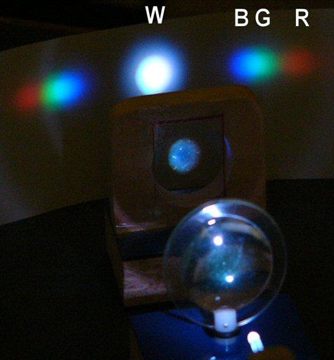
41 Wavelength Division Multiplexing (WDM) 41
Absorption: in an OF, the loss of Optical power, resulting from conversion of that power into heat.
 Absorption: in an OF, the loss of Optical power, resulting from conversion of that power into heat. Scattering: The changes in direction of light confined within an OF, occurring due to imperfection in
Optical fibre. Principle and applications
 Optical fibre Principle and applications Circa 2500 B.C. Earliest known glass Roman times-glass drawn into fibers Venice Decorative Flowers made of glass fibers 1609-Galileo uses optical telescope 1626-Snell
Examination Optoelectronic Communication Technology. April 11, Name: Student ID number: OCT1 1: OCT 2: OCT 3: OCT 4: Total: Grade:
 Examination Optoelectronic Communication Technology April, 26 Name: Student ID number: OCT : OCT 2: OCT 3: OCT 4: Total: Grade: Declaration of Consent I hereby agree to have my exam results published on
Optical systems have carrier frequencies of ~100 THz. This corresponds to wavelengths from µm.
 Introduction A communication system transmits information form one place to another. This could be from one building to another or across the ocean(s). Many systems use an EM carrier wave to transmit information.
Optical Fiber. n 2. n 1. θ 2. θ 1. Critical Angle According to Snell s Law
 ECE 271 Week 10 Critical Angle According to Snell s Law n 1 sin θ 1 = n 1 sin θ 2 θ 1 and θ 2 are angle of incidences The angle of incidence is measured with respect to the normal at the refractive boundary
is a method of transmitting information from one place to another by sending light through an optical fiber. The light forms an electromagnetic
 is a method of transmitting information from one place to another by sending light through an optical fiber. The light forms an electromagnetic carrier wave that is modulated to carry information. The
Functional Materials. Optoelectronic devices
 Functional Materials Lecture 2: Optoelectronic materials and devices (inorganic). Photonic materials Optoelectronic devices Light-emitting diode (LED) displays Photodiode and Solar cell Photoconductive
Geometrical Optics Fiber optics The eye
 Phys 322 Lecture 16 Chapter 5 Geometrical Optics Fiber optics The eye First optical communication Alexander Graham Bell 1847-1922 1880: photophone 4 years after inventing a telephone! Fiberoptics: first
Chapter 3 OPTICAL SOURCES AND DETECTORS
 Chapter 3 OPTICAL SOURCES AND DETECTORS 3. Optical sources and Detectors 3.1 Introduction: The success of light wave communications and optical fiber sensors is due to the result of two technological breakthroughs.
EXAMINATION FOR THE DEGREE OF B.E. and M.E. Semester
 EXAMINATION FOR THE DEGREE OF B.E. and M.E. Semester 2 2009 101908 OPTICAL COMMUNICATION ENGINEERING (Elec Eng 4041) 105302 SPECIAL STUDIES IN MARINE ENGINEERING (Elec Eng 7072) Official Reading Time:
Introduction to Fiber Optics
 Introduction to Fiber Optics Dr. Anurag Srivastava Atal Bihari Vajpayee Indian Institute of Information Technology and Manegement, Gwalior Milestones in Electrical Communication 1838 Samuel F.B. Morse
Fiber Optic Communications Communication Systems
 INTRODUCTION TO FIBER-OPTIC COMMUNICATIONS A fiber-optic system is similar to the copper wire system in many respects. The difference is that fiber-optics use light pulses to transmit information down
Electronics - PHYS 2371/2
 Optoelectronics Communications - Highspeed, femtosec pulses, GHz - Ease of coupling to electronics - Multichannel, indep wavelengths Light Spectrum and Vision - Chromaticity Diagram Spectral Response of
Unit 2 Semiconductor Devices. Lecture_2.5 Opto-Electronic Devices
 Unit 2 Semiconductor Devices Lecture_2.5 Opto-Electronic Devices Opto-electronics Opto-electronics is the study and application of electronic devices that interact with light. Electronics (electrons) Optics
ECE 340 Lecture 29 : LEDs and Lasers Class Outline:
 ECE 340 Lecture 29 : LEDs and Lasers Class Outline: Light Emitting Diodes Lasers Semiconductor Lasers Things you should know when you leave Key Questions What is an LED and how does it work? How does a
PHYSICAL ELECTRONICS(ECE3540) APPLICATIONS OF PHYSICAL ELECTRONICS PART I
 APPLICATIONS OF PHYSICAL ELECTRONICS PART I") PHYSICAL ELECTRONICS(ECE3540) APPLICATIONS OF PHYSICAL ELECTRONICS PART I Tennessee Technological University Monday, October 28, 2013 1 Introduction In the following slides, we will discuss the summary
PHYSICAL ELECTRONICS(ECE3540) APPLICATIONS OF PHYSICAL ELECTRONICS PART I Tennessee Technological University Monday, October 28, 2013 1 Introduction In the following slides, we will discuss the summary
Photonics and Fiber Optics
 1 UNIT V Photonics and Fiber Optics Part-A 1. What is laser? LASER is the acronym for Light Amplification by Stimulated Emission of Radiation. The absorption and emission of light by materials has been
Key Questions. What is an LED and how does it work? How does a laser work? How does a semiconductor laser work? ECE 340 Lecture 29 : LEDs and Lasers
 Things you should know when you leave Key Questions ECE 340 Lecture 29 : LEDs and Class Outline: What is an LED and how does it How does a laser How does a semiconductor laser How do light emitting diodes
COM 46: ADVANCED COMMUNICATIONS jfm 07 FIBER OPTICS
 FIBER OPTICS Fiber optics is a unique transmission medium. It has some unique advantages over conventional communication media, such as copper wire, microwave or coaxial cables. The major advantage is
Introduction Fundamentals of laser Types of lasers Semiconductor lasers
 ECE 5368 Introduction Fundamentals of laser Types of lasers Semiconductor lasers Introduction Fundamentals of laser Types of lasers Semiconductor lasers How many types of lasers? Many many depending on
Electronic devices-i. Difference between conductors, insulators and semiconductors
 Electronic devices-i Semiconductor Devices is one of the important and easy units in class XII CBSE Physics syllabus. It is easy to understand and learn. Generally the questions asked are simple. The unit
William Stallings Data and Computer Communications 7 th Edition. Chapter 4 Transmission Media
 William Stallings Data and Computer Communications 7 th Edition Chapter 4 Transmission Media Overview Guided - wire Unguided - wireless Characteristics and quality determined by medium and signal For guided,
Wallace Hall Academy. CfE Higher Physics. Unit 3 - Electricity Notes Name
 Wallace Hall Academy CfE Higher Physics Unit 3 - Electricity Notes Name 1 Electrons and Energy Alternating current and direct current Alternating current electrons flow back and forth several times per
Optical Fiber Technology. Photonic Network By Dr. M H Zaidi
 Optical Fiber Technology Numerical Aperture (NA) What is numerical aperture (NA)? Numerical aperture is the measure of the light gathering ability of optical fiber The higher the NA, the larger the core
Basic concepts. Optical Sources (b) Optical Sources (a) Requirements for light sources (b) Requirements for light sources (a)
 Optical Sources (a) Requirements for light sources (b) Requirements for light sources (a)") Optical Sources (a) Optical Sources (b) The main light sources used with fibre optic systems are: Light-emitting diodes (LEDs) Semiconductor lasers (diode lasers) Fibre laser and other compact solid-state
Optical Sources (a) Optical Sources (b) The main light sources used with fibre optic systems are: Light-emitting diodes (LEDs) Semiconductor lasers (diode lasers) Fibre laser and other compact solid-state
Part III Optical Communications
 Part III Optical Communications Gong-Ru Lin and Yin-Chieh Lai Introduction The earliest history of optical communication technologies can be dated back to ancient times when smoke and beacon fires were
UNIT-II : SIGNAL DEGRADATION IN OPTICAL FIBERS
 UNIT-II : SIGNAL DEGRADATION IN OPTICAL FIBERS The Signal Transmitting through the fiber is degraded by two mechanisms. i) Attenuation ii) Dispersion Both are important to determine the transmission characteristics
SYLLABUS Optical Fiber Communication
 SYLLABUS Optical Fiber Communication Subject Code : IA Marks : 25 No. of Lecture Hrs/Week : 04 Exam Hours : 03 Total no. of Lecture Hrs. : 52 Exam Marks : 100 UNIT - 1 PART - A OVERVIEW OF OPTICAL FIBER
THIS IS A NEW SPECIFICATION
 THIS IS A NEW SPECIFICATION ADVANCED SUBSIDIARY GCE PHYSICS A Electrons, Waves and Photons G482 * OCE / 1 9082* Candidates answer on the Question Paper OCR Supplied Materials: Data, Formulae and Relationships
Lecture 6 Fiber Optical Communication Lecture 6, Slide 1
 Lecture 6 Optical transmitters Photon processes in light matter interaction Lasers Lasing conditions The rate equations CW operation Modulation response Noise Light emitting diodes (LED) Power Modulation
LEDs, Photodetectors and Solar Cells
 LEDs, Photodetectors and Solar Cells Chapter 7 (Parker) ELEC 424 John Peeples Why the Interest in Photons? Answer: Momentum and Radiation High electrical current density destroys minute polysilicon and
Chapter 1 Introduction
 Wireless Information Transmission System Lab. Chapter 1 Introduction National Sun Yat-sen University Table of Contents Elements of a Digital Communication System Communication Channels and Their Wire-line
EE 43 Smart Dust Lab: Experiment Guide
 Smart Dust Motes EE 43 Smart Dust Lab: Experiment Guide The motes that you ll use are contained in translucent plastic boxes that measure 1.5 x 2.5 x 0.6 cubic inches. There is an insulated antenna (inside
Diodes Rectifiers, Zener diodes light emitting diodes, laser diodes photodiodes, optocouplers
 Diodes Rectifiers, Zener diodes light emitting diodes, laser diodes photodiodes, optocouplers Prepared by Scott Robertson Fall 2007 Physics 3330 1 Impurity-doped semiconductors Semiconductors (Ge, Si)
Semiconductor Lasers Semiconductors were originally pumped by lasers or e-beams First diode types developed in 1962: Create a pn junction in
 Semiconductor Lasers Semiconductors were originally pumped by lasers or e-beams First diode types developed in 1962: Create a pn junction in semiconductor material Pumped now with high current density
Optodevice Data Book ODE I. Rev.9 Mar Opnext Japan, Inc.
 Optodevice Data Book ODE-408-001I Rev.9 Mar. 2003 Opnext Japan, Inc. Section 1 Operating Principles 1.1 Operating Principles of Laser Diodes (LDs) and Infrared Emitting Diodes (IREDs) 1.1.1 Emitting Principles
EC Optical Communication And Networking TWO MARKS QUESTION AND ANSWERS UNIT -1 INTRODUCTION
 EC6702 - Optical Communication And Networking TWO MARKS QUESTION AND ANSWERS UNIT -1 INTRODUCTION Ray Theory Transmission 1. Write short notes on ray optics theory. Laws governing the nature of light are
Lecture 18: Photodetectors
 Lecture 18: Photodetectors Contents 1 Introduction 1 2 Photodetector principle 2 3 Photoconductor 4 4 Photodiodes 6 4.1 Heterojunction photodiode.................... 8 4.2 Metal-semiconductor photodiode................
Class 4 ((Communication and Computer Networks))
)") Class 4 ((Communication and Computer Networks)) Lesson 3... Transmission Media, Part 1 Abstract The successful transmission of data depends principally on two factors: the quality of the signal being transmitted
Class 4 ((Communication and Computer Networks)) Lesson 3... Transmission Media, Part 1 Abstract The successful transmission of data depends principally on two factors: the quality of the signal being transmitted
Photonics and Optical Communication
 Photonics and Optical Communication (Course Number 300352) Spring 2007 Dr. Dietmar Knipp Assistant Professor of Electrical Engineering http://www.faculty.iu-bremen.de/dknipp/ 1 Photonics and Optical Communication
Optical behavior. Reading assignment. Topic 10
 Reading assignment Optical behavior Topic 10 Askeland and Phule, The Science and Engineering of Materials, 4 th Ed.,Ch. 0. Shackelford, Materials Science for Engineers, 6 th Ed., Ch. 16. Chung, Composite
Lectureo5 FIBRE OPTICS. Unit-03
 Lectureo5 FIBRE OPTICS Unit-03 INTRODUCTION FUNDAMENTAL IDEAS ABOUT OPTICAL FIBRE Multimode Fibres Multimode Step Index Fibres Multimode Graded Index Fibres INTRODUCTION In communication systems, there
TECHNICAL ARTICLE: DESIGN BRIEF FOR INDUSTRIAL FIBRE OPTICAL NETWORKS
 TECHNICAL ARTICLE: DESIGN BRIEF FOR INDUSTRIAL FIBRE OPTICAL NETWORKS Designing and implementing a fibre optical based communication network intended to replace or augment an existing communication network
Department of Electrical Engineering and Computer Science
 MASSACHUSETTS INSTITUTE of TECHNOLOGY Department of Electrical Engineering and Computer Science 6.161/6637 Practice Quiz 2 Issued X:XXpm 4/XX/2004 Spring Term, 2004 Due X:XX+1:30pm 4/XX/2004 Please utilize
Optical Receivers Theory and Operation
 Optical Receivers Theory and Operation Photo Detectors Optical receivers convert optical signal (light) to electrical signal (current/voltage) Hence referred O/E Converter Photodetector is the fundamental
Chapter 18: Fiber Optic and Laser Technology
 Chapter 18: Fiber Optic and Laser Technology Chapter 18 Objectives At the conclusion of this chapter, the reader will be able to: Describe the construction of fiber optic cable. Describe the propagation
Instruction manual and data sheet ipca h
 1/15 instruction manual ipca-21-05-1000-800-h Instruction manual and data sheet ipca-21-05-1000-800-h Broad area interdigital photoconductive THz antenna with microlens array and hyperhemispherical silicon
Semiconductor Lasers Semiconductors were originally pumped by lasers or e-beams First diode types developed in 1962: Create a pn junction in
 Semiconductor Lasers Semiconductors were originally pumped by lasers or e-beams First diode types developed in 1962: Create a pn junction in semiconductor material Pumped now with high current density
Lecture 8 Optical Sensing. ECE 5900/6900 Fundamentals of Sensor Design
 ECE 5900/6900: Fundamentals of Sensor Design Lecture 8 Optical Sensing 1 Optical Sensing Q: What are we measuring? A: Electromagnetic radiation labeled as Ultraviolet (UV), visible, or near,mid-, far-infrared
Electronic Systems - B1 23/04/ /04/ SisElnB DDC. Chapter 2
 Politecnico di Torino - ICT school Goup B - goals ELECTRONIC SYSTEMS B INFORMATION PROCESSING B.1 Systems, sensors, and actuators» System block diagram» Analog and digital signals» Examples of sensors»
ELECTRONIC SYSTEMS. Introduction. B1 - Sensors and actuators. Introduction
 Politecnico di Torino - ICT school Goup B - goals ELECTRONIC SYSTEMS B INFORMATION PROCESSING B.1 Systems, sensors, and actuators» System block diagram» Analog and digital signals» Examples of sensors»
Introduction to Optoelectronic Devices
 Introduction to Optoelectronic Devices Dr. Jing Bai Assistant Professor Department of Electrical and Computer Engineering University of Minnesota Duluth October 30th, 2012 1 Outline What is the optoelectronics?
The absorption of the light may be intrinsic or extrinsic
 Attenuation Fiber Attenuation Types 1- Material Absorption losses 2- Intrinsic Absorption 3- Extrinsic Absorption 4- Scattering losses (Linear and nonlinear) 5- Bending Losses (Micro & Macro) Material
Luminous Equivalent of Radiation
 Intensity vs λ Luminous Equivalent of Radiation When the spectral power (p(λ) for GaP-ZnO diode has a peak at 0.69µm) is combined with the eye-sensitivity curve a peak response at 0.65µm is obtained with
FIBER OPTICS. Prof. R.K. Shevgaonkar. Department of Electrical Engineering. Indian Institute of Technology, Bombay. Lecture: 18.
 FIBER OPTICS Prof. R.K. Shevgaonkar Department of Electrical Engineering Indian Institute of Technology, Bombay Lecture: 18 Optical Sources- Introduction to LASER Diodes Fiber Optics, Prof. R.K. Shevgaonkar,
Optical Communications and Networks - Review and Evolution (OPTI 500) Massoud Karbassian
 Massoud Karbassian") Optical Communications and Networks - Review and Evolution (OPTI 500) Massoud Karbassian m.karbassian@arizona.edu Contents Optical Communications: Review Optical Communications and Photonics Why Photonics?
Optical Communications and Networks - Review and Evolution (OPTI 500) Massoud Karbassian m.karbassian@arizona.edu Contents Optical Communications: Review Optical Communications and Photonics Why Photonics?
Università degli Studi di Roma Tor Vergata Dipartimento di Ingegneria Elettronica. Analogue Electronics. Paolo Colantonio A.A.
 Università degli Studi di Roma Tor Vergata Dipartimento di Ingegneria Elettronica Analogue Electronics Paolo Colantonio A.A. 2015-16 Introduction: materials Conductors e.g. copper or aluminum have a cloud
Light Sources, Modulation, Transmitters and Receivers
 Optical Fibres and Telecommunications Light Sources, Modulation, Transmitters and Receivers Introduction Previous section looked at Fibres. How is light generated in the first place? How is light modulated?
Antenna & Propagation. Basic Radio Wave Propagation
 For updated version, please click on http://ocw.ump.edu.my Antenna & Propagation Basic Radio Wave Propagation by Nor Hadzfizah Binti Mohd Radi Faculty of Electric & Electronics Engineering hadzfizah@ump.edu.my
PROJECT REPORT COUPLING OF LIGHT THROUGH FIBER PHY 564 SUBMITTED BY: GAGANDEEP KAUR ( )
") PROJECT REPORT COUPLING OF LIGHT THROUGH FIBER PHY 564 SUBMITTED BY: GAGANDEEP KAUR (952549116) 1 INTRODUCTION: An optical fiber (or fiber) is a glass or plastic fiber that carries light along its length.
PROJECT REPORT COUPLING OF LIGHT THROUGH FIBER PHY 564 SUBMITTED BY: GAGANDEEP KAUR (952549116) 1 INTRODUCTION: An optical fiber (or fiber) is a glass or plastic fiber that carries light along its length.
Optical Fiber Communication
 A Seminar report On Optical Fiber Communication Submitted in partial fulfillment of the requirement for the award of degree Of Mechanical SUBMITTED TO: www.studymafia.org SUBMITTED BY: www.studymafia.org
NON-AMPLIFIED PHOTODETECTOR USER S GUIDE
 NON-AMPLIFIED PHOTODETECTOR USER S GUIDE Thank you for purchasing your Non-amplified Photodetector. This user s guide will help answer any questions you may have regarding the safe use and optimal operation
Lecture 1: Introduction
 Optical Fibre Communication Systems Lecture 1: Introduction Professor Z Ghassemlooy Electronics & It Division School of Engineering Sheffield Hallam University U.K. www.shu.ac.uk/ocr 1 Contents Reading
Maximum date rate=2hlog 2 V bits/sec. Maximum number of bits/sec=hlog 2 (1+S/N)
") Basics Data can be analog or digital. The term analog data refers to information that is continuous, digital data refers to information that has discrete states. Analog data take on continuous values.
Basics Data can be analog or digital. The term analog data refers to information that is continuous, digital data refers to information that has discrete states. Analog data take on continuous values.
Optical Amplifiers. Continued. Photonic Network By Dr. M H Zaidi
 Optical Amplifiers Continued EDFA Multi Stage Designs 1st Active Stage Co-pumped 2nd Active Stage Counter-pumped Input Signal Er 3+ Doped Fiber Er 3+ Doped Fiber Output Signal Optical Isolator Optical
Chapter 9 GUIDED WAVE OPTICS
 [Reading Assignment, Hecht 5.6] Chapter 9 GUIDED WAVE OPTICS Optical fibers The step index circular waveguide is the most common fiber design for optical communications plastic coating (sheath) core cladding
Data and Computer Communications Chapter 4 Transmission Media
 Data and Computer Communications Chapter 4 Transmission Media Ninth Edition by William Stallings Data and Computer Communications, Ninth Edition by William Stallings, (c) Pearson Education - Prentice Hall,
CHAPTER -15. Communication Systems
 CHAPTER -15 Communication Systems COMMUNICATION Communication is the act of transmission and reception of information. COMMUNICATION SYSTEM: A system comprises of transmitter, communication channel and
INTRODUCTION TO COMMUNICATION SYSTEMS AND TRANSMISSION MEDIA
 COMM.ENG INTRODUCTION TO COMMUNICATION SYSTEMS AND TRANSMISSION MEDIA 9/9/2017 LECTURES 1 Objectives To give a background on Communication system components and channels (media) A distinction between analogue
The electric field for the wave sketched in Fig. 3-1 can be written as
 ELECTROMAGNETIC WAVES Light consists of an electric field and a magnetic field that oscillate at very high rates, of the order of 10 14 Hz. These fields travel in wavelike fashion at very high speeds.
Objective Type Questions 1. Why pure semiconductors are insulators at 0 o K? 2. What is effect of temperature on barrier voltage? 3.
 Objective Type Questions 1. Why pure semiconductors are insulators at 0 o K? 2. What is effect of temperature on barrier voltage? 3. What is difference between electron and hole? 4. Why electrons have
Omni-directional Free Space Optical Laser Communication MERIT Kenneth Tukei. University of Maryland, College Park. Maryland Optics Group
 Omni-directional Free Space Optical Laser Communication MERIT 2007 Kenneth Tukei University of Maryland, College Park Dr. Christopher Davis Faculty Advisor Navik Agrawal Graduate Student Advisor Maryland
Surname. Number OXFORD CAMBRIDGE AND RSA EXAMINATIONS ADVANCED SUBSIDIARY GCE G482 PHYSICS A. Electrons, Waves and Photons
 Candidate Forename Centre Number Candidate Surname Candidate Number OXFORD CAMBRIDGE AND RSA EXAMINATIONS ADVANCED SUBSIDIARY GCE G482 PHYSICS A Electrons, Waves and Photons WEDNESDAY 13 JANUARY 2010:
Section B Lecture 5 FIBER CHARACTERISTICS
 Section B Lecture 5 FIBER CHARACTERISTICS Material absorption Losses Material absorption is a loss mechanism related to material composition and fabrication process for the fiber. This results in dissipation
PSD Characteristics. Position Sensing Detectors
 PSD Characteristics Position Sensing Detectors Silicon photodetectors are commonly used for light power measurements in a wide range of applications such as bar-code readers, laser printers, medical imaging,
Fiberoptic and Waveguide Sensors
 Fiberoptic and Waveguide Sensors Wei-Chih Wang Department of Mecahnical Engineering University of Washington Optical sensors Advantages: -immune from electromagnetic field interference (EMI) - extreme
Chapter 3 Signal Degradation in Optical Fibers
 What about the loss in optical fiber? Why and to what degree do optical signals gets distorted as they propagate along a fiber? Fiber links are limited by in path length by attenuation and pulse distortion.
Chemistry Instrumental Analysis Lecture 10. Chem 4631
 Chemistry 4631 Instrumental Analysis Lecture 10 Types of Instrumentation Single beam Double beam in space Double beam in time Multichannel Speciality Types of Instrumentation Single beam Requires stable
Lasers PH 645/ OSE 645/ EE 613 Summer 2010 Section 1: T/Th 2:45-4:45 PM Engineering Building 240
 Lasers PH 645/ OSE 645/ EE 613 Summer 2010 Section 1: T/Th 2:45-4:45 PM Engineering Building 240 John D. Williams, Ph.D. Department of Electrical and Computer Engineering 406 Optics Building - UAHuntsville,
SIGNAL RECOVERY: Sensors, Signals, Noise and Information Recovery
 SIGNAL RECOVERY: Sensors, Signals, Noise and Information Recovery http://home.deib.polimi.it/cova/ 1 Signal Recovery COURSE OUTLINE Scenery preview: typical examples and problems of Sensors and Signal
E2-E3 CONSUMER FIXED ACCESS. CHAPTER-4 OVERVIEW OF OFC NETWORK (Date Of Creation: )
") E2-E3 CONSUMER FIXED ACCESS CHAPTER-4 OVERVIEW OF OFC NETWORK (Date Of Creation: 01-04-2011) Page: 1 Overview Of OFC Network Learning Objective: Optical Fiber concept & types OFC route and optical budget
E2-E3 CONSUMER FIXED ACCESS CHAPTER-4 OVERVIEW OF OFC NETWORK (Date Of Creation: 01-04-2011) Page: 1 Overview Of OFC Network Learning Objective: Optical Fiber concept & types OFC route and optical budget
First and second order systems. Part 1: First order systems: RC low pass filter and Thermopile. Goals: Department of Physics
 slide 1 Part 1: First order systems: RC low pass filter and Thermopile Goals: Understand the behavior and how to characterize first order measurement systems Learn how to operate: function generator, oscilloscope,
Experiments in Photonics
 Experiments in Photonics Section 3: Electronics & Photonics An integrated electronic/photonic device. Photograph courtesy of Quantum Optics Group, Australian National University Minilabs 2006 1 Electronics
Fiberoptic Communication Systems By Dr. M H Zaidi. Optical Amplifiers
 Optical Amplifiers Optical Amplifiers Optical signal propagating in fiber suffers attenuation Optical power level of a signal must be periodically conditioned Optical amplifiers are a key component in
UNIT Write notes on broadening of pulse in the fiber dispersion?
 UNIT 3 1. Write notes on broadening of pulse in the fiber dispersion? Ans: The dispersion of the transmitted optical signal causes distortion for both digital and analog transmission along optical fibers.
Diode Limiters or Clipper Circuits
 Diode Limiters or Clipper Circuits Circuits which are used to clip off portions of signal voltages above or below certain levels are called limiters or clippers. Types of Clippers Positive Clipper Negative
International Journal of Advanced Research in Computer Science and Software Engineering
 ISSN: 2277 128X International Journal of Advanced Research in Computer Science and Software Engineering Research Paper Available online at: Performance Analysis of WDM/SCM System Using EDFA Mukesh Kumar
NEW YORK CITY COLLEGE of TECHNOLOGY
 NEW YORK CITY COLLEGE of TECHNOLOGY THE CITY UNIVERSITY OF NEW YORK DEPARTMENT OF ELECTRICAL AND TELECOMMUNICATIONS ENGINEERING TECHNOLOGY Course : Prepared by: TCET 4102 Fiber-optic communications Module
Marconi Challenge: Infrared Data Transmission as the 21 st Century Crystal Radio
 : Infrared Data Transmission as the 21 st Century Crystal Radio Dennis Silage ECE Temple University A simple and inexpensive yet challenging project 21 st century crystal radio Guglielmo Marconi pioneered
Scintillation Counters
 PHY311/312 Detectors for Nuclear and Particle Physics Dr. C.N. Booth Scintillation Counters Unlike many other particle detectors, which exploit the ionisation produced by the passage of a charged particle,
Guided Propagation Along the Optical Fiber. Xavier Fernando Ryerson Comm. Lab
 Guided Propagation Along the Optical Fiber Xavier Fernando Ryerson Comm. Lab The Nature of Light Quantum Theory Light consists of small particles (photons) Wave Theory Light travels as a transverse electromagnetic
Measure the roll-off frequency of an acousto-optic modulator
 Slide 1 Goals of the Lab: Get to know some of the properties of pin photodiodes Measure the roll-off frequency of an acousto-optic modulator Measure the cut-off frequency of a pin photodiode as a function
Spectroscopy in the UV and Visible: Instrumentation. Spectroscopy in the UV and Visible: Instrumentation
 Spectroscopy in the UV and Visible: Instrumentation Typical UV-VIS instrument 1 Source - Disperser Sample (Blank) Detector Readout Monitor the relative response of the sample signal to the blank Transmittance
Problem 4 Consider a GaAs p-n + junction LED with the following parameters at 300 K: Electron diusion coecient, D n = 25 cm 2 =s Hole diusion coecient
 Prof. Jasprit Singh Fall 2001 EECS 320 Homework 7 This homework is due on November 8. Problem 1 An optical power density of 1W/cm 2 is incident on a GaAs sample. The photon energy is 2.0 ev and there is
Ph 77 ADVANCED PHYSICS LABORATORY ATOMIC AND OPTICAL PHYSICS
 Ph 77 ADVANCED PHYSICS LABORATORY ATOMIC AND OPTICAL PHYSICS Diode Laser Characteristics I. BACKGROUND Beginning in the mid 1960 s, before the development of semiconductor diode lasers, physicists mostly
Antennas and Propagation
 Antennas and Propagation Chapter 5 Introduction An antenna is an electrical conductor or system of conductors Transmission - radiates electromagnetic energy into space Reception - collects electromagnetic
Advanced Optical Communications Prof. R. K. Shevgaonkar Department of Electrical Engineering Indian Institute of Technology, Bombay
 Advanced Optical Communications Prof. R. K. Shevgaonkar Department of Electrical Engineering Indian Institute of Technology, Bombay Lecture No. # 27 EDFA In the last lecture, we talked about wavelength
Electronics The basics of semiconductor physics
 Electronics The basics of semiconductor physics Prof. Márta Rencz, Gábor Takács BME DED 17/09/2015 1 / 37 The basic properties of semiconductors Range of conductivity [Source: http://www.britannica.com]
Guided Propagation Along the Optical Fiber
 Guided Propagation Along the Optical Fiber The Nature of Light Quantum Theory Light consists of small particles (photons) Wave Theory Light travels as a transverse electromagnetic wave Ray Theory Light
Why Using Fiber for transmission
 Why Using Fiber for transmission Why Using Fiber for transmission Optical fibers are widely used in fiber-optic communications, where they permit transmission over long distances and at very high bandwidths.