Section B Lecture 5 FIBER CHARACTERISTICS
|
|
|
- Muriel Wilson
- 5 years ago
- Views:
Transcription
1 Section B Lecture 5 FIBER CHARACTERISTICS
2 Material absorption Losses Material absorption is a loss mechanism related to material composition and fabrication process for the fiber. This results in dissipation of some of the transmitted optical power as heat in the wave guide. Absorption Intrinsic (due to major components of glass) Extrinsic (caused by impurities)
3 Material absorption Losses (contd.) The attenuation spectra for the intrinsic loss mechanisms in pure GeO 2 SiO 2 glass
4 Material absorption Losses (contd.) Attn. Spectra for intrinsic loss mechanism in pure GeO 2 SiO 2 Glass Pure silicate glass has little intrinsic absorption, due to its basic material structure in the near infra red red region. Loss is due to stimulation of electron transitions ii within ihi Glass!
5 Extrinsic Absorption It is due to impurities (metal elements) Impurities Loss (due to 1 part in 10 9 ) in db/km Cr Cu Fe Ni These transition element impurities can be reduced to acceptable levels (one part in ) by glass refining techniques. Another major extrinsic loss mechanism is due to water (oh ion) dissolved in glass. At 0.95µm 1.38µm, ATTN is 1 2 db/km (1 ppm of OH)
6 Extrinsic Absorption (Contd.) Lowest ATTN for this fiber occurs at a wavelength of 155µm 1.55 and is about 02db/Km 0.2db/Km (Min possible is 0.18 db/km.)
7 Two types of linear scattering Rayleigh Scattering MIE Scattering Rayleigh Scattering Linear Scattering Dominant intrinsic loss mechanism between ultraviolet and infrared absorption regions. It is due to changes in ref. index (inhomogeneties of a random nature ) The inhomogeneties are because of density & composition variations which are frozen into glass lattice on cooling. Glass is composed of randomlyconnected network of molecules.
8 Rayleigh Scattering(contd) Attenuation γ R = 8 3 n 8 p 2 β c K T F 3λ 4 (Rayleigh Scattering Co efficient) p=average photo elastic coefficient β c = Isothermal compressibility at a fictive temp. K= Boltzman s Constant T F= temp at which glass can reach a state of thermal equilibrium.
9 MIE Scattering This results from non perfect cylindrical structure of the waveguide, and fiber imperfections, eg. Core, cladding interface irregularities Ref. index variation along fiber length Dia. fluctuations Strains a s & bubbles.
10 MIE Scattering(contd) Scattering created is in the forward direction. The inhomogenties can be reduced by removing imperfections due to glass mfg. process. controlled extrusion & coating of fiber. Increasing the fiber guidanceby increasing the relative ref. index difference. Note: There is no change of freq. on scattering with all linear processes.
11 TRANMISSION CHARACTERISTICS OF FIBERS Attenuation ( or loss) Band width Unit of attenuation: db db= 10 log 10 P i / P o where P i = input opt. power into the fiber P o = output opt. power By dfiii definition : 10 db/10 = P i / P o In OFC,attenuation is generally expressed in decibels per unit length ( db/km )
12 TRANSMISSION CHARACHTERISTICS OF FIBERS α db.l =10 log 10 P i / P o where, α is the signal attenuation per unit length & L is fiber length. Note : OFC became specially attractive when transmission losses of fibers were reduced below those of competing metallicconductors. t (< 5dB / km )
13 TRANSMISSION CHARACHTERISTICS OF FIBERS (contd) BANDWIDTH This is limited by the signal dispersion within thefiber fiber, which determines the no of bits of information transmitted in a given time period. Note : Today wideband fiber bandwidths of many tens of GHz over a number of Km are available
14 DISPERSION DISPERSION MECHANISM CAUSES BROADENING OF THE TRANSMITTED LIGHT PULSES. (AS THEY TRAVEL ALONG THE CHANNEL) EACH PULSE BROADENS AND OVERLAPS WITH ITS NEIGHBOURS. THE EFFECT IS KNOWN AS INTERSYMBOL INTERFERENCE (ISI)
15 ISI ISI RESULTS IN AN ERROR RATE WHICH IS A FUNCTION OF SIGNAL ATTENUATION AND SNR AT THE RECEIVER. SIGNAL DISPERSION LIMITS THE MAX. BANDWIDTH ATTAINABLE (TOTHE THE POINT WHERE INDIVIDUAL SYMBOLS CAN NO LONGER BEDISTINGUISHED
16 INTERSYMBOL INTERREFRENCE (ISI) Amplitude Amplitude Amplitude A ill t ti i th di it l bit tt 1011 f th b d i f li ht l An illustration using the digital bit pattern 1011 of the broadening of light pulses as they are transmitted along a fiber: (a) fiber input; (b) fiber output at a distance L1;(c) fiber output at a distance L2> L1.
17 FOR NO OVERLAPPING OF LIGHT PULSES DIGITAL BIT RATE, B T 1/2τ WHERE τ = INPUT PULSE DURATION = PULSE BROADENING DUE TO DISPERSION ALTERNATIVELY B T = (1/4σ)/(1/ 5σ) WHERE σ = RMS WIDTH OF GAUSSIAN SHAPE AT THE OUTPUT.
18
19 INTRAMODAL DISPERSION OPTICAL SOURCES DO NOT EMIT JUST A SINGLE FREQ, BUT A BAND OF FREQUENCIES. THIS RESULTS IN PROPAGATIQNAL DELAY DIFFERENCES BETWEEN THE DIFFERENT SPECTRAL COMPONENTS OF THE Tx SIGNAL. THIS CAUSES BROADENING OF EACH TRANSMITTED MODE (INTRAMODAL DISPERSION). THE INTRAMODAL DISPERSIONMAY BE CAUSED BY MATERIAL THE INTRAMODAL DISPERSION MAY BE CAUSED BY MATERIAL DISPERSION AND WAVE GUIDE DISPERSION.
20 MATERIAL DISPERSION PULSE BROADENING RESULTS FROM PULSE BROADENING RESULTS FROM DIFF.GROUP VELOCITIES OF VARIOUS SPECTRAL COMPONENTS LAUNCHED INTO OPTICAL FIBRE SOURCE. PHASE VELOCITY OF WAVE VARIES NON LINEARLY WITH WAVELENGTH. A MATERIAL IS SAID TO EXHIBIT MATERIAL DISPERSION WHEN d 2 n/ dλ ns / km in multimode fibers
21 The material dispersion parameter for silica as a function of wavelength.
22 WAVE GUIDE DISPERSION THIS RESULTS FROM VARIATION IN GROUP VELOCITY WITH WAVELENGTH FOR A PARTICULAR MODE. IT IS EQUIVALENT TO VARIATION OF ANGLE BETWEEN RAY AND FIBER AXIS WITH WAVELENGTH, RESULTING IN VARIATION IN TRANSMISSION TIMES FOR THE RAYS, AND HENCE DISPERSION. SINGLE MODE FIBER EXHIBITS WAVEGUIDE DISPERSION WHEN d 2 β/dλ2 0 MULTIMODE FIBERS ARE NORMALLY FREE OF WAVEGUIDE MULTIMODE FIBERS ARE NORMALLY FREE OF WAVEGUIDE DISPERSION.
23 INTERM0DAL / MODAL/ MODE DISPERSION. PULSE BROADENING RESULTS FROM THE PROPAGATION DELAY DIFFERENCES BETWEEN MODES WITHIN A MULTIMODE FIBER DIFFERENT MODES IN A MULTIMODE FIBER TRAVEL ALONG THE CHANNEL AT DIFFERENT GROUP VELOCITIES.
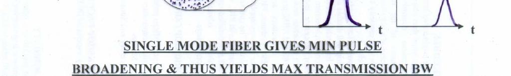
24 INTERM0DAL / MODAL/ MODE DISPERSION MULTIMODE STEP INDEX FIBERS EXHIBIT MAX INTERMODAL DISPERSION. GRADED INDEX FIBERS EXHIBIT FAR LESS PULSE BROADENING THAN THE ABOVE CASE (TYPICALLY BY A FACTOR OF 100). SO HIGHER BW IS AVAILABLE. SINGLE MODE STEP INDEX FIBERS EXHIBIT LEAST PULSE BROADENING AND HENCE THE GREATEST POSSIBLE BW.
25 REDUCING INTERMODAL DISPERSION BY ADOPTION OF AN OPTIMUM REF. INDEX PROFILE GRADING THE CORE REFRACTIVE INDEX TO FOLLOW A NEAR PARABOLIC PROFILE.
26 DISPERSION SHIFTED FIBERS Refractive Index profile can be modified in order to tune to zero dispersion wavelength point Shift to a longer wavelength by reducing the core dia and increasing the fractional refractive index difference(fig) Higher concentration of the dopant causes a shift to longer wavelength
27 DISPERSION SHIFTED FIBERS(contd) Increased dopant level however causes higher h loss ( 2 db / km ). This is overcome by using triangular profile. The loss is reduced to 024dB 0.24 / km at a wavelength of µm (fig) The triangular profile is sensitive to bend induced losses. Remedy is to employ a triangular index profile combined with depressed cladding index or use a guassian refractive index profile. (fig)
28 Total dispersion characteristics for the various types of single mode fiber.
29 Refractive index profile of a step index dispersion shifted fiber (solid) with a conventional nonshifted profile design (dashed)
30 Refractive index profiles for graded index dispersion shifted fibers: a) triangular profile ; b) depressed cladding triangular profile c) Gaussian profile
UNIT-II : SIGNAL DEGRADATION IN OPTICAL FIBERS
 UNIT-II : SIGNAL DEGRADATION IN OPTICAL FIBERS The Signal Transmitting through the fiber is degraded by two mechanisms. i) Attenuation ii) Dispersion Both are important to determine the transmission characteristics
The absorption of the light may be intrinsic or extrinsic
 Attenuation Fiber Attenuation Types 1- Material Absorption losses 2- Intrinsic Absorption 3- Extrinsic Absorption 4- Scattering losses (Linear and nonlinear) 5- Bending Losses (Micro & Macro) Material
Chapter 3 Signal Degradation in Optical Fibers
 What about the loss in optical fiber? Why and to what degree do optical signals gets distorted as they propagate along a fiber? Fiber links are limited by in path length by attenuation and pulse distortion.
Optical Fiber Technology. Photonic Network By Dr. M H Zaidi
 Optical Fiber Technology Numerical Aperture (NA) What is numerical aperture (NA)? Numerical aperture is the measure of the light gathering ability of optical fiber The higher the NA, the larger the core
Photonics and Optical Communication
 Photonics and Optical Communication (Course Number 300352) Spring 2007 Dr. Dietmar Knipp Assistant Professor of Electrical Engineering http://www.faculty.iu-bremen.de/dknipp/ 1 Photonics and Optical Communication
Guided Propagation Along the Optical Fiber. Xavier Fernando Ryerson University
 Guided Propagation Along the Optical Fiber Xavier Fernando Ryerson University The Nature of Light Quantum Theory Light consists of small particles (photons) Wave Theory Light travels as a transverse electromagnetic
Guided Propagation Along the Optical Fiber. Xavier Fernando Ryerson Comm. Lab
 Guided Propagation Along the Optical Fiber Xavier Fernando Ryerson Comm. Lab The Nature of Light Quantum Theory Light consists of small particles (photons) Wave Theory Light travels as a transverse electromagnetic
UNIT List the requirements that be satisfied by materials used to manufacture optical fiber? ANS: Fiber Materials
 UNIT- 2 1. List the requirements that be satisfied by materials used to manufacture optical fiber? ANS: Fiber Materials Most of the fibers are made up of glass consisting of either Silica (SiO 2 ) or.silicate.
SIGNAL DEGRADATION IN OPTICAL FIBERS
 Volume Issue January 04, ISSN 348 8050 SIGNAL DEGRADATION IN OPTICAL FIBERS Gyan Prakash Pal, Manishankar Gupta,,, Assistant Professor, Electronics & Communication Engineering Department, Shanti Institute
Lecture 10. Dielectric Waveguides and Optical Fibers
 Lecture 10 Dielectric Waveguides and Optical Fibers Slab Waveguide, Modes, V-Number Modal, Material, and Waveguide Dispersions Step-Index Fiber, Multimode and Single Mode Fibers Numerical Aperture, Coupling
Types of losses in optical fiber cable are: Due to attenuation, the power of light wave decreases exponentially with distance.
 UNIT-II TRANSMISSION CHARACTERISTICS OF OPTICAL FIBERS SIGNAL ATTENUATION: Signal attenuation in an optical fiber is defined as the decrease in light power during light propagation along an optical fiber.
Guided Propagation Along the Optical Fiber
 Guided Propagation Along the Optical Fiber The Nature of Light Quantum Theory Light consists of small particles (photons) Wave Theory Light travels as a transverse electromagnetic wave Ray Theory Light
Waveguides and Optical Fibers
 Waveguides and Optical Fibers Dielectric Waveguides Light Light Light n n Light n > n A planar dielectric waveguide has a central rectangular region of higher refractive index n than the surrounding region
Losses and Dispersion in Waveguides
 Losses and Dispersion in Waveguides Wei-Chih WangInstitute of Nanoengineeirng and Microsystems National Tsing Hua University 1 Week 13 Course Website: http://courses.washington.edu/me557/sensors Reading
EC Optical Communication And Networking TWO MARKS QUESTION AND ANSWERS UNIT -1 INTRODUCTION
 EC6702 - Optical Communication And Networking TWO MARKS QUESTION AND ANSWERS UNIT -1 INTRODUCTION Ray Theory Transmission 1. Write short notes on ray optics theory. Laws governing the nature of light are
DIELECTRIC WAVEGUIDES and OPTICAL FIBERS
 DIELECTRIC WAVEGUIDES and OPTICAL FIBERS Light Light Light n 2 n 2 Light n 1 > n 2 A planar dielectric waveguide has a central rectangular region of higher refractive index n 1 than the surrounding region
Fiber Optic Communications Communication Systems
 INTRODUCTION TO FIBER-OPTIC COMMUNICATIONS A fiber-optic system is similar to the copper wire system in many respects. The difference is that fiber-optics use light pulses to transmit information down
MAHALAKSHMI ENGINEERING COLLEGE TIRUCHIRAPALLI
 MAHALAKSHMI ENGINEERING COLLEGE TIRUCHIRAPALLI - 621213 DEPARTMENT : ECE SUBJECT NAME : OPTICAL COMMUNICATION & NETWORKS SUBJECT CODE : EC 2402 UNIT II: TRANSMISSION CHARACTERISTICS OF OPTICAL FIBERS PART
SKP Engineering College
 SKP Engineering College Tiruvannamalai 606611 A Course Material on Optical Communication and Networks By M.Mageshbabu Assistant Professor Electronics and Communication Engineering Department Electronics
τ mod = T modal = longest ray path shortest ray path n 1 L 1 = L n 2 1
 S. Blair February 15, 2012 23 2.2. Pulse dispersion Pulse dispersion is the spreading of a pulse as it propagates down an optical fiber. Pulse spreading is an obvious detrimental effect that limits the
UNIT Write notes on broadening of pulse in the fiber dispersion?
 UNIT 3 1. Write notes on broadening of pulse in the fiber dispersion? Ans: The dispersion of the transmitted optical signal causes distortion for both digital and analog transmission along optical fibers.
Lecture 8 Fiber Optical Communication Lecture 8, Slide 1
 Lecture 8 Bit error rate The Q value Receiver sensitivity Sensitivity degradation Extinction ratio RIN Timing jitter Chirp Forward error correction Fiber Optical Communication Lecture 8, Slide Bit error
Lecture 3 Fiber Optical Communication Lecture 3, Slide 1
 Lecture 3 Dispersion in single-mode fibers Material dispersion Waveguide dispersion Limitations from dispersion Propagation equations Gaussian pulse broadening Bit-rate limitations Fiber losses Fiber Optical
Chapter 2: Fiber Optics as a communication medium
 Chapter 2: Fiber Optics as a communication medium 2.1 Fiber Fabrication: Basically, fiber manufacturers use two methods to fabricate multimode and single mode glass fibers. One method is vapor phase oxidation,
Fiber Optic Communication Systems. Unit-05: Types of Fibers. https://sites.google.com/a/faculty.muet.edu.pk/abdullatif
 Unit-05: Types of Fibers https://sites.google.com/a/faculty.muet.edu.pk/abdullatif Department of Telecommunication, MUET UET Jamshoro 1 Optical Fiber Department of Telecommunication, MUET UET Jamshoro
Absorption: in an OF, the loss of Optical power, resulting from conversion of that power into heat.
 Absorption: in an OF, the loss of Optical power, resulting from conversion of that power into heat. Scattering: The changes in direction of light confined within an OF, occurring due to imperfection in
Module 12 : System Degradation and Power Penalty
 Module 12 : System Degradation and Power Penalty Lecture : System Degradation and Power Penalty Objectives In this lecture you will learn the following Degradation during Propagation Modal Noise Dispersion
Optical networking. Emilie CAMISARD GIP RENATER Optical technologies engineer Advanced IP Services
 Optical networking Emilie CAMISARD GIP RENATER Optical technologies engineer Advanced IP Services Agenda Optical fibre principle Time Division Multiplexing (TDM) Wavelength Division Multiplexing (WDM)
EE 233. LIGHTWAVE. Chapter 2. Optical Fibers. Instructor: Ivan P. Kaminow
 EE 233. LIGHTWAVE SYSTEMS Chapter 2. Optical Fibers Instructor: Ivan P. Kaminow PLANAR WAVEGUIDE (RAY PICTURE) Agrawal (2004) Kogelnik PLANAR WAVEGUIDE a = (n s 2 - n c2 )/ (n f 2 - n s2 ) = asymmetry;
2 in the multipath dispersion of the optical fibre. (b) Discuss the merits and drawbacks of cut bouls method of measurement of alternation.
 Discuss the merits and drawbacks of cut bouls method of measurement of alternation.") B.TECH IV Year I Semester (R09) Regular Examinations, November 2012 1 (a) Derive an expression for multiple time difference tt 2 in the multipath dispersion of the optical fibre. (b) Discuss the merits
B.TECH IV Year I Semester (R09) Regular Examinations, November 2012 1 (a) Derive an expression for multiple time difference tt 2 in the multipath dispersion of the optical fibre. (b) Discuss the merits
2. The Basic principle of optical fibre (Or) Working principle of optical fibre (or) Total internal reflection
 Working principle of optical fibre (or) Total internal reflection") Introduction Fibre optics deals with the light propagation through thin glass fibres. Fibre optics plays an important role in the field of communication to transmit voice, television and digital data signals
Introduction Fibre optics deals with the light propagation through thin glass fibres. Fibre optics plays an important role in the field of communication to transmit voice, television and digital data signals
Study of Optical Fiber Design Parameters in Fiber Optics Communications
 Kurdistan Journal of Applied Research (KJAR) Print-ISSN: 2411-7684 Electronic-ISSN: 2411-7706 kjar.spu.edu.iq Volume 2 Issue 3 August 2017 DOI: 10.24017/science.2017.3.52 Study of Optical Fiber Design
Antennas and Propagation
 Antennas and Propagation Chapter 5 Introduction An antenna is an electrical conductor or system of conductors Transmission - radiates electromagnetic energy into space Reception - collects electromagnetic
Optical systems have carrier frequencies of ~100 THz. This corresponds to wavelengths from µm.
 Introduction A communication system transmits information form one place to another. This could be from one building to another or across the ocean(s). Many systems use an EM carrier wave to transmit information.
Geometrical Optics Fiber optics The eye
 Phys 322 Lecture 16 Chapter 5 Geometrical Optics Fiber optics The eye First optical communication Alexander Graham Bell 1847-1922 1880: photophone 4 years after inventing a telephone! Fiberoptics: first
Optical behavior. Reading assignment. Topic 10
 Reading assignment Optical behavior Topic 10 Askeland and Phule, The Science and Engineering of Materials, 4 th Ed.,Ch. 0. Shackelford, Materials Science for Engineers, 6 th Ed., Ch. 16. Chung, Composite
Optical fibre. Principle and applications
 Optical fibre Principle and applications Circa 2500 B.C. Earliest known glass Roman times-glass drawn into fibers Venice Decorative Flowers made of glass fibers 1609-Galileo uses optical telescope 1626-Snell
Photonics and Optical Communication Spring 2005
 Photonics and Optical Communication Spring 2005 Final Exam Instructor: Dr. Dietmar Knipp, Assistant Professor of Electrical Engineering Name: Mat. -Nr.: Guidelines: Duration of the Final Exam: 2 hour You
Fiberoptic and Waveguide Sensors
 Fiberoptic and Waveguide Sensors Wei-Chih Wang Department of Mecahnical Engineering University of Washington Optical sensors Advantages: -immune from electromagnetic field interference (EMI) - extreme
Optical Fiber. n 2. n 1. θ 2. θ 1. Critical Angle According to Snell s Law
 ECE 271 Week 10 Critical Angle According to Snell s Law n 1 sin θ 1 = n 1 sin θ 2 θ 1 and θ 2 are angle of incidences The angle of incidence is measured with respect to the normal at the refractive boundary
Lectureo5 FIBRE OPTICS. Unit-03
 Lectureo5 FIBRE OPTICS Unit-03 INTRODUCTION FUNDAMENTAL IDEAS ABOUT OPTICAL FIBRE Multimode Fibres Multimode Step Index Fibres Multimode Graded Index Fibres INTRODUCTION In communication systems, there
Antennas and Propagation
 Mobile Networks Module D-1 Antennas and Propagation 1. Introduction 2. Propagation modes 3. Line-of-sight transmission 4. Fading Slides adapted from Stallings, Wireless Communications & Networks, Second
Fiber Optic Communication Link Design
 Fiber Optic Communication Link Design By Michael J. Fujita, S.K. Ramesh, PhD, Russell L. Tatro Abstract The fundamental building blocks of an optical fiber transmission link are the optical source, the
Intensity Modulation. Wei-Chih Wang Department of Mechanical Engineering University of Washington. W. Wang
 Intensity Modulation Wei-Chih Wang Department of Mechanical Engineering University of Washington Why Intensity Modulation Simple optical setup Broadband or mono-chormatic light source Less sensitive but
EC6702-OPTICAL COMMUNICTION AND NETWORKS VII SEM. ECE
 EC6702- OPTICAL COMMUNICATION AND NETWORKING TWO MARKS QUESTIONS AND ANSWERS UNIT I - Introduction 1. What are the limitations of optical fiber communication systems? Optical fiber is made up of glass.
Photonics and Fiber Optics
 1 UNIT V Photonics and Fiber Optics Part-A 1. What is laser? LASER is the acronym for Light Amplification by Stimulated Emission of Radiation. The absorption and emission of light by materials has been
Examination Optoelectronic Communication Technology. April 11, Name: Student ID number: OCT1 1: OCT 2: OCT 3: OCT 4: Total: Grade:
 Examination Optoelectronic Communication Technology April, 26 Name: Student ID number: OCT : OCT 2: OCT 3: OCT 4: Total: Grade: Declaration of Consent I hereby agree to have my exam results published on
End Capped High Power Assemblies
 Fiberguide s end capped fiber optic assemblies allow the user to achieve higher coupled power into a fiber core by reducing the power density at the air/ silica interface, commonly the point of laser damage.
WIRELESS COMMUNICATION TECHNOLOGIES (16:332:546) LECTURE 5 SMALL SCALE FADING
 LECTURE 5 SMALL SCALE FADING") WIRELESS COMMUNICATION TECHNOLOGIES (16:332:546) LECTURE 5 SMALL SCALE FADING Instructor: Dr. Narayan Mandayam Slides: SabarishVivek Sarathy A QUICK RECAP Why is there poor signal reception in urban clutters?
WIRELESS COMMUNICATION TECHNOLOGIES (16:332:546) LECTURE 5 SMALL SCALE FADING Instructor: Dr. Narayan Mandayam Slides: SabarishVivek Sarathy A QUICK RECAP Why is there poor signal reception in urban clutters?
Industrial Automation
 OPTICAL FIBER. SINGLEMODE OR MULTIMODE It is important to understand the differences between singlemode and multimode fiber optics before selecting one or the other at the start of a project. Its different
Broadcast and distribution networks
 4/7/06 SYSTEM ARCHITECTURES Point-to-point links Point-to-point links constitute the simplest kind of lightwave systems The link length can vary from less than a kilometer (short haul) to thousands of
Chapter 8. Digital Links
 Chapter 8 Digital Links Point-to-point Links Link Power Budget Rise-time Budget Power Penalties Dispersions Noise Content Photonic Digital Link Analysis & Design Point-to-Point Link Requirement: - Data
ECE 476/ECE 501C/CS Wireless Communication Systems Winter Lecture 6: Fading
 ECE 476/ECE 501C/CS 513 - Wireless Communication Systems Winter 2005 Lecture 6: Fading Last lecture: Large scale propagation properties of wireless systems - slowly varying properties that depend primarily
Session2 Antennas and Propagation
 Wireless Communication Presented by Dr. Mahmoud Daneshvar Session2 Antennas and Propagation 1. Introduction Types of Anttenas Free space Propagation 2. Propagation modes 3. Transmission Problems 4. Fading
Analysis of Dispersion of Single Mode Optical Fiber
 Daffodil International University Institutional Repository Proceedings of NCCIS November 007 007-11-4 Analysis of Dispersion of Single Mode Optical Fiber Hossen, Monir Daffodil International University
ECE 476/ECE 501C/CS Wireless Communication Systems Winter Lecture 6: Fading
 ECE 476/ECE 501C/CS 513 - Wireless Communication Systems Winter 2003 Lecture 6: Fading Last lecture: Large scale propagation properties of wireless systems - slowly varying properties that depend primarily
Antennas & Propagation. CSG 250 Fall 2007 Rajmohan Rajaraman
 Antennas & Propagation CSG 250 Fall 2007 Rajmohan Rajaraman Introduction An antenna is an electrical conductor or system of conductors o Transmission - radiates electromagnetic energy into space o Reception
Wireless Physical Layer Concepts: Part II
 Wireless Physical Layer Concepts: Part II Raj Jain Professor of CSE Washington University in Saint Louis Saint Louis, MO 63130 Jain@cse.wustl.edu Audio/Video recordings of this lecture are available at:
Fiber Optic Principles. Oct-09 1
 Fiber Optic Principles Oct-09 1 Fiber Optic Basics Optical fiber Active components Attenuation Power budget Bandwidth Oct-09 2 Reference www.flukenetworks.com/fiber Handbook Fiber Optic Technologies (Vivec
ECE 476/ECE 501C/CS Wireless Communication Systems Winter Lecture 6: Fading
 ECE 476/ECE 501C/CS 513 - Wireless Communication Systems Winter 2004 Lecture 6: Fading Last lecture: Large scale propagation properties of wireless systems - slowly varying properties that depend primarily
NEW YORK CITY COLLEGE of TECHNOLOGY
 NEW YORK CITY COLLEGE of TECHNOLOGY THE CITY UNIVERSITY OF NEW YORK DEPARTMENT OF ELECTRICAL AND TELECOMMUNICATIONS ENGINEERING TECHNOLOGY Course : Prepared by: TCET 4102 Fiber-optic communications Module
Total care for networks. Introduction to Dispersion
 Introduction to Dispersion Introduction to PMD Version1.0- June 01, 2000 Copyright GN Nettest 2000 Introduction To Dispersion Contents Definition of Dispersion Chromatic Dispersion Polarization Mode Dispersion
Muhammad Ali Jinnah University, Islamabad Campus, Pakistan. Fading Channel. Base Station
 Fading Lecturer: Assoc. Prof. Dr. Noor M Khan Department of Electronic Engineering, Muhammad Ali Jinnah University, Islamabad Campus, Islamabad, PAKISTAN Ph: +9 (51) 111-878787, Ext. 19 (Office), 186 (ARWiC
Multimode Optical Fiber
 Multimode Optical Fiber 1 OBJECTIVE Determine the optical modes that exist for multimode step index fibers and investigate their performance on optical systems. 2 PRE-LAB The backbone of optical systems
Optical Fibre Amplifiers Continued
 1 Optical Fibre Amplifiers Continued Stavros Iezekiel Department of Electrical and Computer Engineering University of Cyprus ECE 445 Lecture 09 Fall Semester 2016 2 ERBIUM-DOPED FIBRE AMPLIFIERS BASIC
UNIT I INTRODUCTION TO OPTICAL FIBERS
 UNIT I INTRODUCTION TO OPTICAL FIBERS 9 Evolution of fiber optic system Element of an Optical Fiber Transmission link Total internal reflection Acceptance angle Numerical aperture Skew rays Ray Optics
Antennas and Propagation. Chapter 5
 Antennas and Propagation Chapter 5 Introduction An antenna is an electrical conductor or system of conductors Transmission - radiates electromagnetic energy into space Reception - collects electromagnetic
COM 46: ADVANCED COMMUNICATIONS jfm 07 FIBER OPTICS
 FIBER OPTICS Fiber optics is a unique transmission medium. It has some unique advantages over conventional communication media, such as copper wire, microwave or coaxial cables. The major advantage is
EENG473 Mobile Communications Module 3 : Week # (12) Mobile Radio Propagation: Small-Scale Path Loss
 Mobile Radio Propagation: Small-Scale Path Loss") EENG473 Mobile Communications Module 3 : Week # (12) Mobile Radio Propagation: Small-Scale Path Loss Introduction Small-scale fading is used to describe the rapid fluctuation of the amplitude of a radio
EENG473 Mobile Communications Module 3 : Week # (12) Mobile Radio Propagation: Small-Scale Path Loss Introduction Small-scale fading is used to describe the rapid fluctuation of the amplitude of a radio
FIBER OPTICS. Prof. R.K. Shevgaonkar. Department of Electrical Engineering. Indian Institute of Technology, Bombay. Lecture: 4
 FIBER OPTICS Prof. R.K. Shevgaonkar Department of Electrical Engineering Indian Institute of Technology, Bombay Lecture: 4 Modal Propagation of Light in an Optical Fiber Fiber Optics, Prof. R.K. Shevgaonkar,
Fiber designs for high figure of merit and high slope dispersion compensating fibers
 25 Springer Science+Business Media Inc. DOI: 1.17/s1297-5-61-1 Originally published in J. Opt. Fiber. Commun. Rep. 3, 25 6 (25) Fiber designs for high figure of merit and high slope dispersion compensating
Department of Electrical Engineering and Computer Science
 MASSACHUSETTS INSTITUTE of TECHNOLOGY Department of Electrical Engineering and Computer Science 6.161/6637 Practice Quiz 2 Issued X:XXpm 4/XX/2004 Spring Term, 2004 Due X:XX+1:30pm 4/XX/2004 Please utilize
Wireless Channel Propagation Model Small-scale Fading
 Wireless Channel Propagation Model Small-scale Fading Basic Questions T x What will happen if the transmitter - changes transmit power? - changes frequency? - operates at higher speed? Transmit power,
SPECIFICATION. FOR SINGLE-MODE OPTICAL FIBER (FutureGuide -SR15E)
") Fujikura DATE Aug. 18, 2008 NO. JFS-00052A Supersedes JFS-00052 Messrs. SPECIFICATION FOR SINGLE-MODE OPTICAL FIBER (FutureGuide -SR15E) Prepared by H. KIKUCHI Manager Optical Fiber and Cable Dept. Global
Fujikura DATE Aug. 18, 2008 NO. JFS-00052A Supersedes JFS-00052 Messrs. SPECIFICATION FOR SINGLE-MODE OPTICAL FIBER (FutureGuide -SR15E) Prepared by H. KIKUCHI Manager Optical Fiber and Cable Dept. Global
EC LIGHT WAVE COMMUNICATION. To know principle of light wave communication and the characteristics of optical devices.
 EC010 803 LIGHT WAVE COMMUNICATION Objectives To understand the behavior of light wave To know principle of light wave communication and the characteristics of optical devices. Module 1 (12hrs) : Recollection
Notes on Optical Amplifiers
 Notes on Optical Amplifiers Optical amplifiers typically use energy transitions such as those in atomic media or electron/hole recombination in semiconductors. In optical amplifiers that use semiconductor
The electric field for the wave sketched in Fig. 3-1 can be written as
 ELECTROMAGNETIC WAVES Light consists of an electric field and a magnetic field that oscillate at very high rates, of the order of 10 14 Hz. These fields travel in wavelike fashion at very high speeds.
Optical Fiber Communication
 A Seminar report On Optical Fiber Communication Submitted in partial fulfillment of the requirement for the award of degree Of Mechanical SUBMITTED TO: www.studymafia.org SUBMITTED BY: www.studymafia.org
OPTICAL NETWORKS. Building Blocks. A. Gençata İTÜ, Dept. Computer Engineering 2005
 OPTICAL NETWORKS Building Blocks A. Gençata İTÜ, Dept. Computer Engineering 2005 Introduction An introduction to WDM devices. optical fiber optical couplers optical receivers optical filters optical amplifiers
Class 4 ((Communication and Computer Networks))
)") Class 4 ((Communication and Computer Networks)) Lesson 3... Transmission Media, Part 1 Abstract The successful transmission of data depends principally on two factors: the quality of the signal being transmitted
Class 4 ((Communication and Computer Networks)) Lesson 3... Transmission Media, Part 1 Abstract The successful transmission of data depends principally on two factors: the quality of the signal being transmitted
Photonic Crystal Slot Waveguide Spectrometer for Detection of Methane
 Photonic Crystal Slot Waveguide Spectrometer for Detection of Methane Swapnajit Chakravarty 1, Wei-Cheng Lai 2, Xiaolong (Alan) Wang 1, Che-Yun Lin 2, Ray T. Chen 1,2 1 Omega Optics, 10306 Sausalito Drive,
Multi-Path Fading Channel
 Instructor: Prof. Dr. Noor M. Khan Department of Electronic Engineering, Muhammad Ali Jinnah University, Islamabad Campus, Islamabad, PAKISTAN Ph: +9 (51) 111-878787, Ext. 19 (Office), 186 (Lab) Fax: +9
DEFINITIONS AND FUNDAMENTAL PRINCIPLES IDC
 DEFINITIONS AND FUNDAMENTAL PRINCIPLES Data Communications Information is transmitted between two points in the form of data. Analog» Varying amplitude, phase and frequency Digital» In copper systems represented
Optical Digital Transmission Systems. Xavier Fernando ADROIT Lab Ryerson University
 Optical Digital Transmission Systems Xavier Fernando ADROIT Lab Ryerson University Overview In this section we cover point-to-point digital transmission link design issues (Ch8): Link power budget calculations
InP-based Waveguide Photodetector with Integrated Photon Multiplication
 InP-based Waveguide Photodetector with Integrated Photon Multiplication D.Pasquariello,J.Piprek,D.Lasaosa,andJ.E.Bowers Electrical and Computer Engineering Department University of California, Santa Barbara,
CHAPTER 4 RESULTS. 4.1 Introduction
 CHAPTER 4 RESULTS 4.1 Introduction In this chapter focus are given more on WDM system. The results which are obtained mainly from the simulation work are presented. In simulation analysis, the study will
Fiber Optics IV - Testing
 PDHonline Course E311 (3 PDH) Fiber Optics IV - Testing Instructor: Lee Layton, PE 2012 PDH Online PDH Center 5272 Meadow Estates Drive Fairfax, VA 22030-6658 Phone & Fax: 703-988-0088 www.pdhonline.org
Transmitting Light: Fiber-optic and Free-space Communications Holography
 1 Lecture 9 Transmitting Light: Fiber-optic and Free-space Communications Holography 2 Wireless Phone Calls http://havilandtelconews.com/2011/10/the-reality-behind-wireless-networks/ 3 Undersea Cable and
Channel. Muhammad Ali Jinnah University, Islamabad Campus, Pakistan. Multi-Path Fading. Dr. Noor M Khan EE, MAJU
 Instructor: Prof. Dr. Noor M. Khan Department of Electronic Engineering, Muhammad Ali Jinnah University, Islamabad Campus, Islamabad, PAKISTAN Ph: +9 (51) 111-878787, Ext. 19 (Office), 186 (Lab) Fax: +9
Characterization of Fiber Bragg Grating for Dispersion Compensation
 Instituto de Engenharia de Sistemas e Computadores do Porto Faculdade de Engenharia da Universidade do Porto Licenciatura em Engenharia Electrotécnica e de Computadores Characterization of Fiber Bragg
WIRELESS COMMUNICATIONS PRELIMINARIES
 WIRELESS COMMUNICATIONS Preliminaries Radio Environment Modulation Performance PRELIMINARIES db s and dbm s Frequency/Time Relationship Bandwidth, Symbol Rate, and Bit Rate 1 DECIBELS Relative signal strengths
Advanced Fibre Testing: Paving the Way for High-Speed Networks. Trevor Nord Application Specialist JDSU (UK) Ltd
 Ltd") Advanced Fibre Testing: Paving the Way for High-Speed Networks Trevor Nord Application Specialist JDSU (UK) Ltd Fibre Review Singlemode Optical Fibre Elements of Loss Fibre Attenuation - Caused by scattering
Advanced Fibre Testing: Paving the Way for High-Speed Networks Trevor Nord Application Specialist JDSU (UK) Ltd Fibre Review Singlemode Optical Fibre Elements of Loss Fibre Attenuation - Caused by scattering
Antennas and Propagation. Chapter 5
 Antennas and Propagation Chapter 5 Introduction An antenna is an electrical conductor or system of conductors Transmission - radiates electromagnetic energy into space Reception - collects electromagnetic
is a method of transmitting information from one place to another by sending light through an optical fiber. The light forms an electromagnetic
 is a method of transmitting information from one place to another by sending light through an optical fiber. The light forms an electromagnetic carrier wave that is modulated to carry information. The
Bragg and fiber gratings. Mikko Saarinen
 Bragg and fiber gratings Mikko Saarinen 27.10.2009 Bragg grating - Bragg gratings are periodic perturbations in the propagating medium, usually periodic variation of the refractive index - like diffraction
OPTOELECTRONIC and PHOTOVOLTAIC DEVICES
 OPTOELECTRONIC and PHOTOVOLTAIC DEVICES Outline 1. Introduction to the (semiconductor) physics: energy bands, charge carriers, semiconductors, p-n junction, materials, etc. 2. Light emitting diodes Light
EXAMINATION FOR THE DEGREE OF B.E. and M.E. Semester
 EXAMINATION FOR THE DEGREE OF B.E. and M.E. Semester 2 2009 101908 OPTICAL COMMUNICATION ENGINEERING (Elec Eng 4041) 105302 SPECIAL STUDIES IN MARINE ENGINEERING (Elec Eng 7072) Official Reading Time:
CHAPTER 5 SPECTRAL EFFICIENCY IN DWDM
 61 CHAPTER 5 SPECTRAL EFFICIENCY IN DWDM 5.1 SPECTRAL EFFICIENCY IN DWDM Due to the ever-expanding Internet data traffic, telecommunication networks are witnessing a demand for high-speed data transfer.
arxiv:physics/ v1 [physics.optics] 25 Aug 2003
![arxiv:physics/ v1 [physics.optics] 25 Aug 2003](/thumbs/84/90868967.jpg "arxiv:physics/ v1 [physics.optics] 25 Aug 2003") arxiv:physics/0308087v1 [physics.optics] 25 Aug 2003 Multi-mode photonic crystal fibers for VCSEL based data transmission N. A. Mortensen, 1 M. Stach, 2 J. Broeng, 1 A. Petersson, 1 H. R. Simonsen, 1 and
arxiv:physics/0308087v1 [physics.optics] 25 Aug 2003 Multi-mode photonic crystal fibers for VCSEL based data transmission N. A. Mortensen, 1 M. Stach, 2 J. Broeng, 1 A. Petersson, 1 H. R. Simonsen, 1 and
Optical Transport Tutorial
 Optical Transport Tutorial 4 February 2015 2015 OpticalCloudInfra Proprietary 1 Content Optical Transport Basics Assessment of Optical Communication Quality Bit Error Rate and Q Factor Wavelength Division