Waveguides and Optical Fibers
|
|
|
- Eustacia Hill
- 5 years ago
- Views:
Transcription
1 Waveguides and Optical Fibers
2 Dielectric Waveguides Light Light Light n n Light n > n A planar dielectric waveguide has a central rectangular region of higher refractive index n than the surrounding region which has a refractive index n. It is assumed that the waveguide is infinitely wide and the central region is of thickness a. It is illuminated at one end by a monochromatic light source.
3 A plane wave propagate a waveguide with a n/n core-cladding, along Z-direction. Waveguide condition E k B A C n Light n n d = a y x z ΔΦ (AC) = k(ab + BC) - Φ = m(π), k = kn = πn/λ m=0,,, BC = d/cosθ and AB = BC cos(θ) A light ray travelling in the guide must interfere constructively with itself to propagate successfully. Otherwise destructive interference will destroy the wave. 999 S.O. Kasap, Optoelectronics (Prentice Hall) m k n sin m n a sin m cos k m k m m m n cos m cos m
4 E E y z, t E cos k y cos t z k y, 0 y, z, t E ( y) cos t z m m m m m m m Field of evanescent wave (exponential decay) y n Field of guided wave E(y) m = 0 E(y,z,t) = E(y)cos(t 0 z) Light n n The electric field pattern of the lowest mode traveling wave along the guide. This mode has m = 0 and the lowest. It is often referred to as th glazing incidence ray. It has the highest phase velocity along the guide. 999 S.O. Kasap, Optoelectronics (Prentice Hall)
5 y n Cladding E(y) m = 0 m = m = Core n a n Cladding The electric field patterns of the first three modes (m = 0,, ) traveling wave along the guide. Notice different extents of field penetration into the cladding. 999 S.O. Kasap, Optoelectronics (Prentice Hall)
6 High order mode Low order mode Ey (m) is the field distribution along y axis and constitute a mode of propagation. Intensity Ligh t pulse Cladding Core Broadened light pulse Intensity m is called mode number. Defines the number of modes traveling along the waveguide. For every value of m we have an angle θm satisfying the waveguide condition provided to satisfy the TIR as well. Considering these condition one can show that the number of modes should satisfy: m (V Φ)/π 0 t Axial Spread, Schematic illustration of light propagation in a slab dielectric waveguide. Light pulse entering the waveguide breaks up into various modes whic h then propagate at differen group velocities down the guide. At the end of the guide, the modes combine to constitute the output light pulse which is broader than the input light pulse. 999 S.O. Kasap, Optoelectronics (Prentice H all) t V a n n V is called V-number and it is a characteristic parameter of the waveguide For V π/, m= 0, it is the lowest mode of propagation referred to single mode waveguides. The cut-off wavelength (frequency) is a free space wavelength for v = π/ For V=π/, The wavelength is the cut-off wavelength, above this wavelength only one-mode (m=0) will propagate
7 (a) TE mode (b) TM mode y B // B y E // E y B z E E z B O z x (into paper) Possible modes can be classified in terms of (a) transelectric field (TE) and (b) transmagnetic field (TM). Plane of incidence is the paper. 999 S.O. Kasap, Optoelectronics (P rentice Hall)
8 y y Cladding > c > v g Core v g > v g < cut-off < E(y) Cladding The electric field of TE 0 mode extends more into the cladding as the wavelength increases. As more of the field is carried by the cladding, the group velocity increases. 999 S.O. Kasap, Optoelectronics (Prentice Hall)
9 Goos-Hanchen shift y B Virtual reflecting plane n Penetration depth, z A i z r n > n Incident light Reflected light The reflected light beam in total internal reflection appears to have been laterally s hifted by an amount z at the interface. 999 S.O. Kasap, Optoelectronics (P rentice Hall)
10 Optical Tunneling y C n B A i r n n > n d z Incident light Reflected light When medium B is thin (thickness d is small), the field penetrates to the BC interface and gives rise to an attenuated wave in medium C. The effect is the tunnelling of the incident beam in A through B to C. 999 S.O. Kasap, Optoelectronics (P rent ice Hall)
11 Waveguide Dispersion Intermodal dispersion: In multimode waveguides the lowest mode has the slowest group velocity, the highest mode has the highest group velocity L V n V c g min g max n y y Cladding Intramodal Dispersion; In single mode waveguide: Waveguide Dispersion: as there is no prefect monochromatic light Material Dispersion: due to the n(λ) E(y) > c v g < cut-off Core Cladding > < v g > v g The electric field of TE 0 mode extends more into the cladding as the wavelength increases. As more of the field is carried by the cladding, the group velocity increases. 999 S.O. Kasap, Optoelectronics (Prentice Hall)
12 y y Cladding Core r z Fiber axis n n n The step index optical fiber. The central region, the core, has greater refractive index than the outer region, the cladding. The fiber has cylindrical symmetry. We use the coordinates r,, z to represent any point in the fiber. Cladding is normally much thicker than shown. 999 S.O. Kasap, Optoelectronics (Prentice Hall) Along the fiber Meridional ray Fiber axis 3, 3 (a) A meridiona ray always crosses the fibe axis. Fiber axis 3 Skew ray (b) A skew ray does not have to cross the fiber axis. It zigzags around the fiber axis. Ray path along the fiber Ray path projected on to a plane normal to fiber axis Illustration of the difference between a meridional ray and a skew ray. Numbers represent reflections of the ray. 999 S.O. Kasap, Optoelectronics (Prentice Hall) For the step index optical fiber Δ = (n n)/n is called normalized index difference
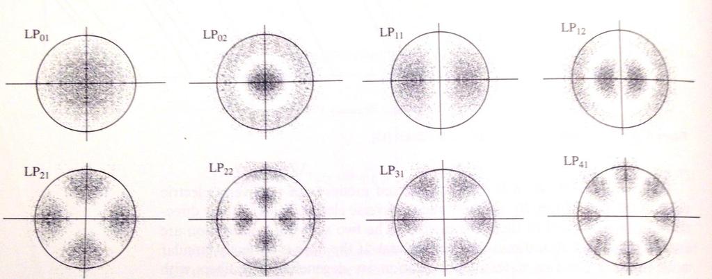
13 For weakly guided fibers, i.e.: (a) The electric field of the fundamental mode (b) The intensity in the fundamental mode LP 0 (c) The intensity in LP (d) The intensity in LP n n n n n n Core Cladding E The guide modes are visualized by traveling waves that are almost polarized, called linearly polarized (LP) E S.O. Kasap, Optoelectronics (Prentice Hall) r The electric field distribution of the fundamental mod in the transverse plane to the fiber axis z. The light intensity is greatest at the center of the fiber. Intensity patterns in LP 0, LP and LP modes. LPs (linearly polarized waves) propagating along the fiber have either TE or TM type represented by the propagation of an electric field distribution E lm (r,ɸ) along z. E LP E lm r. exp jt z ELP is the field of the LP mode and βlm is its propagation constant along z. lm
14
15 V-number n n / n n n / n Normalized index difference V cutoff a c n n. 405 For weakly guided fiber Δ=0.0, 0.005,.. For V =.405, the fiber is called single mode (only the fundamental mode propagate along the fiber). For V >.405 the number of mode increases according to approximately V M Most SM fibers designed with.5<v<.4
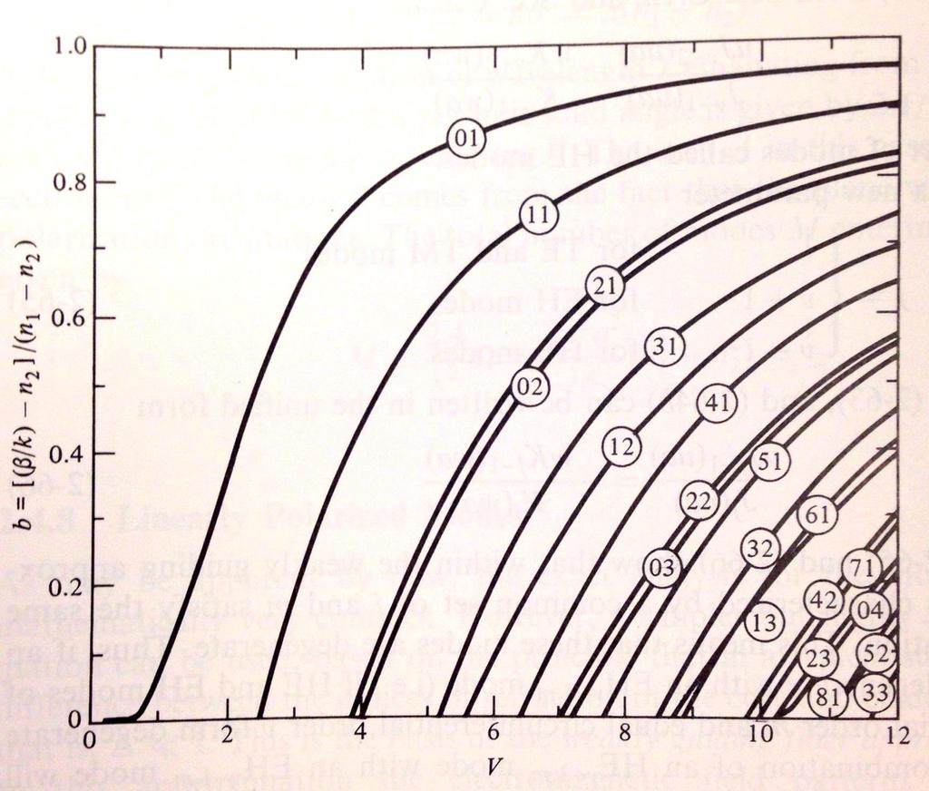
16 Since β lm of an LP mode depends on the waveguide properties and the source wavelength, the light Propagation is described in terms of a normalized propagation constant that depends only on the V-number. a V b 0.8 a n n n n LP 0 LP 0.6 b / k n n n LP LP 0 kn <β<kn Propagation condition V b changes between 0 and Normalized propagation constant b vs. V-number for a step index fiber for various LP modes. 999 S.O. Kasap, Optoelectronics (Prentice Hall)
17
18 sin max o sin(90 ) sin c sin max c n n n n n 0 Numerical Aperture---Maximum Acceptance Angle n n 0 max A B max n n 0 n < c Fiber axis Lost B > c Cladding Core 999 S.O. Kasap, Optoelectronics (Prentice Hall) Propagates A Maximum acceptance angle max is that which just gives total internal reflection at the core-cladding interface, i.e. when = max then = c. Rays with > max (e.g. ray B) become refracted and penetrate the cladding and are eventually lost. NA sin max ( n n / ) NA n 0 Numerical aperture V a NA Example values for n =.48, n =.47; very close numbers Typical values of NA = 0.07,0.5
19 Optical waveguides display 3 types of dispersion: These are the main sources of dispersion in the fibers. L D Material dispersion: different wavelength of light travel at different velocities within a given medium. Due to the variation of n of the core wrt wavelength of the light. Waveguide dispersion: β depends on the wavelength, so even within a single mode different wavelengths will propagate at slightly different speeds. Due to the variation of group velocity wrt V- number Emitter Intensity Intensity Intensity Spectrum, ² o Input Very short light pulse 0 v g ( ) t v g ( ) Cladding Core Output Spread, ² All excitation sources are inherently non-monochromatic and emit within a spectrum, ², of wavelengths. Waves in the guide with different free space wavelengths travel at different group velocities due to the wavelength dependence of n. The waves arrive at the end of the fiber at different times and hence result in a broadened output pulse. 999 S.O. Kasap, Optoelectronics (Prentice Hall) t
20 Modal dispersion, in waveguides with more than one propagating mode. Modes travel with different group velocities. Intensity 0 Ligh t pulse t High order mode Cladding Core Axial Low order mode Broadened light pulse Intensity Spread, t Due to the number of modes traveling along the fiber with different group velocity and different path. Schematic illustration of light propagation in a slab dielectric waveguide. Light pulse entering the waveguide breaks up into various modes whic h then propagate at differen group velocities down the guide. At the end of the guide, the modes combine to constitute the output light pulse which is broader than the input light pulse. 999 S.O. Kasap, Optoelectronics (Prentice H all)
21 L D m Dispersion coefficient (ps km - nm - ) 30 0 Dm D m L D d n c d L D.984N g a cn D P Material Dispersion Coefficient Waveguide Dispersion Coefficient D p is called profile dispersion; group velocity depends on Δ Dm + Dw D w (m) Material dispersion coefficient (D m ) for the core material (taken as SiO ), waveguide dispersion coefficient (D w ) (a = 4. m) and the total or chromatic dispersion coefficient D ch (= D m + D w ) as a function of free space wavelength, L D D m D p 999 S.O. Kasap, Optoelectronics (Prentice Hall)
22 Polarization Dispersion Intensity n y // y Core Out put light pulse z E x t n x // x E y E x E y = Pulse spread t E Input light p ulse Suppose that the core refractive index has different values along two orthogonal directions corres ponding to electric field os cillation direc tion (polarizations). We can take x and y axes along these directions. An input light w ill travel along the fiber w ith E x and E y polarizations having different group velocities and hence arrive at the output at different times 999 S.O. Kasap, Optoelectronics (Prentice Hall)
23 Dispersion coefficient (ps km - nm - ) 0 D m 0 SiO -3.5%GeO e.g. For λ =.5, and a = 8μm D m =0 ps/km.nm and D w =-6 ps/km.nm (m) D w a (m) Material and waveguide dispersion coefficients in an optical fiber with a core SiO -3.5%GeO for a =.5 to 4 m S.O. Kasap, Optoelectronics (Prentice Hall)
24 Dispersion coefficient (ps km - nm - ) 30 n 0 0 D m r 0-0 D ch = D m + D w D w (m) Thin layer of cladding with a depressed index Dispersion flattened fiber example. The material dispersion coefficient ( D m ) for the core material and waveguide dispersion coefficient (D w ) for the doubly clad fiber result in a flattened small chromatic dispersion between and. 999 S.O. Kasap, Optoelectronics (Prentice Hall)
25 Fiber Information Digital signal Emitter t Input Photodetector Information Output Input Intensity Output Intensity ² Very short light pulses 0 T t 0 t ~² An optical fiber link for transmitting digital information and the effect of dispersion in the fiber on the output pulses. 999 S.O. Kasap, Optoelectronics (Prentice Hall)
26 n O 3 n n (a) Multimode step index fiber. Ray paths are different so that rays arrive at different times. O O' O'' 3 3 n n n (b) Graded index fiber. Ray paths are different but so are the velocities along the paths so that all the rays arrive at the same time. n 999 S.O. Kasap, Optoelectronics (Prentice Hall)
27 0.5P 0.5P 0.3P O O' O O (a) (b) (c) Graded index (GRIN) rod lenses of different pitches. (a) Point O is on the rod face center and the lens focuses the rays onto O' on to the center of the opposite face. (b) The rays from O on the rod face center are collimated out. (c) O is slightly away from the rod face and the rays are collimated out. 999 S.O. Kasap, Optoelectronics (Prentice Hall)
28 Sources of Loss and Attenuation in Fibers A solid with ions Absorption depends on materials, amount of materials, wavelength, and the impurities in the substances. E x Light direction k z It is cumulative and depends on the amount of materials, e.g. length of the fiber optics. ( ) d Lattice absorption through a crystal. The field in the wave oscillates the ions which consequently generate "mechanical" waves in the crystal; energy is thereby transferred from the wave to lattice vibrations. 999 S.O. Kas ap, Optoelectronics (Prentice Hall) α is the absorption per unit length and d is the distance that light travels
29 A dielectric particle smaller than wavelength Incident wave Through wave Scattered waves Rayleigh scattering involves the polarization of a small dielectric particle or a region that is much smaller than the light wavelength. The field forces dipole oscillations in the particle (by polarizing it) which leads to the emission of EM waves in "many" directions so that a portion of the light energy is directed away from the incident beam. 999 S.O. Kasap, Optoelectronics (Prentice Hall)
30 Field distribution Microbending Cladding Escaping wave Core c R Sharp bends change the local waveguide geometry that can lead to waves escaping. The zigzagging ray suddenly finds itself with an incidence angle that gives rise to either a transmitted wave, or to a greater cladding penetration; the field reaches the outside medium and some light energy is lost. 999 S.O. Kasap, Optoelectronics (Prentice Hall)

 34 4. db G.")
31 Attenuation in Optical Fiber P db out 0 log( L P in ( e L ) P P in out ) db G. Keiser (Ref. )
DIELECTRIC WAVEGUIDES and OPTICAL FIBERS
 DIELECTRIC WAVEGUIDES and OPTICAL FIBERS Light Light Light n 2 n 2 Light n 1 > n 2 A planar dielectric waveguide has a central rectangular region of higher refractive index n 1 than the surrounding region
Guided Propagation Along the Optical Fiber. Xavier Fernando Ryerson University
 Guided Propagation Along the Optical Fiber Xavier Fernando Ryerson University The Nature of Light Quantum Theory Light consists of small particles (photons) Wave Theory Light travels as a transverse electromagnetic
Guided Propagation Along the Optical Fiber. Xavier Fernando Ryerson Comm. Lab
 Guided Propagation Along the Optical Fiber Xavier Fernando Ryerson Comm. Lab The Nature of Light Quantum Theory Light consists of small particles (photons) Wave Theory Light travels as a transverse electromagnetic
Guided Propagation Along the Optical Fiber
 Guided Propagation Along the Optical Fiber The Nature of Light Quantum Theory Light consists of small particles (photons) Wave Theory Light travels as a transverse electromagnetic wave Ray Theory Light
Lecture 10. Dielectric Waveguides and Optical Fibers
 Lecture 10 Dielectric Waveguides and Optical Fibers Slab Waveguide, Modes, V-Number Modal, Material, and Waveguide Dispersions Step-Index Fiber, Multimode and Single Mode Fibers Numerical Aperture, Coupling
Fiber Optic Communication Systems. Unit-05: Types of Fibers. https://sites.google.com/a/faculty.muet.edu.pk/abdullatif
 Unit-05: Types of Fibers https://sites.google.com/a/faculty.muet.edu.pk/abdullatif Department of Telecommunication, MUET UET Jamshoro 1 Optical Fiber Department of Telecommunication, MUET UET Jamshoro
1. Evolution Of Fiber Optic Systems
 OPTICAL FIBER COMMUNICATION UNIT-I : OPTICAL FIBERS STRUCTURE: 1. Evolution Of Fiber Optic Systems The operating range of optical fiber system term and the characteristics of the four key components of
Chapter 3 Signal Degradation in Optical Fibers
 What about the loss in optical fiber? Why and to what degree do optical signals gets distorted as they propagate along a fiber? Fiber links are limited by in path length by attenuation and pulse distortion.
Fiber Optic Communications Communication Systems
 INTRODUCTION TO FIBER-OPTIC COMMUNICATIONS A fiber-optic system is similar to the copper wire system in many respects. The difference is that fiber-optics use light pulses to transmit information down
Optical Fiber Technology. Photonic Network By Dr. M H Zaidi
 Optical Fiber Technology Numerical Aperture (NA) What is numerical aperture (NA)? Numerical aperture is the measure of the light gathering ability of optical fiber The higher the NA, the larger the core
UNIT-II : SIGNAL DEGRADATION IN OPTICAL FIBERS
 UNIT-II : SIGNAL DEGRADATION IN OPTICAL FIBERS The Signal Transmitting through the fiber is degraded by two mechanisms. i) Attenuation ii) Dispersion Both are important to determine the transmission characteristics
Section B Lecture 5 FIBER CHARACTERISTICS
 Section B Lecture 5 FIBER CHARACTERISTICS Material absorption Losses Material absorption is a loss mechanism related to material composition and fabrication process for the fiber. This results in dissipation
Examination Optoelectronic Communication Technology. April 11, Name: Student ID number: OCT1 1: OCT 2: OCT 3: OCT 4: Total: Grade:
 Examination Optoelectronic Communication Technology April, 26 Name: Student ID number: OCT : OCT 2: OCT 3: OCT 4: Total: Grade: Declaration of Consent I hereby agree to have my exam results published on
SIGNAL DEGRADATION IN OPTICAL FIBERS
 Volume Issue January 04, ISSN 348 8050 SIGNAL DEGRADATION IN OPTICAL FIBERS Gyan Prakash Pal, Manishankar Gupta,,, Assistant Professor, Electronics & Communication Engineering Department, Shanti Institute
Study of Optical Fiber Design Parameters in Fiber Optics Communications
 Kurdistan Journal of Applied Research (KJAR) Print-ISSN: 2411-7684 Electronic-ISSN: 2411-7706 kjar.spu.edu.iq Volume 2 Issue 3 August 2017 DOI: 10.24017/science.2017.3.52 Study of Optical Fiber Design
FIBER OPTICS. Prof. R.K. Shevgaonkar. Department of Electrical Engineering. Indian Institute of Technology, Bombay. Lecture: 4
 FIBER OPTICS Prof. R.K. Shevgaonkar Department of Electrical Engineering Indian Institute of Technology, Bombay Lecture: 4 Modal Propagation of Light in an Optical Fiber Fiber Optics, Prof. R.K. Shevgaonkar,
Photonics and Optical Communication
 Photonics and Optical Communication (Course Number 300352) Spring 2007 Dr. Dietmar Knipp Assistant Professor of Electrical Engineering http://www.faculty.iu-bremen.de/dknipp/ 1 Photonics and Optical Communication
The absorption of the light may be intrinsic or extrinsic
 Attenuation Fiber Attenuation Types 1- Material Absorption losses 2- Intrinsic Absorption 3- Extrinsic Absorption 4- Scattering losses (Linear and nonlinear) 5- Bending Losses (Micro & Macro) Material
Geometrical Optics Fiber optics The eye
 Phys 322 Lecture 16 Chapter 5 Geometrical Optics Fiber optics The eye First optical communication Alexander Graham Bell 1847-1922 1880: photophone 4 years after inventing a telephone! Fiberoptics: first
Optical systems have carrier frequencies of ~100 THz. This corresponds to wavelengths from µm.
 Introduction A communication system transmits information form one place to another. This could be from one building to another or across the ocean(s). Many systems use an EM carrier wave to transmit information.
Glass Processing. Younès Messaddeq Centre d optique, Photonique et laser,québec, Canada Spring 2015 JIRU
 Glass Processing Lecture 19 # Introduction to Dielectric Waveguide Younès Messaddeq Centre d optique, Photonique et laser,québec, Canada (younes.messaddeq@copl.ulaval.ca) Spring 2015 Lectures available
Fiber Optic Communication Systems. Unit-04: Theory of Light. https://sites.google.com/a/faculty.muet.edu.pk/abdullatif
 Unit-04: Theory of Light https://sites.google.com/a/faculty.muet.edu.pk/abdullatif Department of Telecommunication, MUET UET Jamshoro 1 Limitations of Ray theory Ray theory describes only the direction
Photograph of the rectangular waveguide components
 Waveguides Photograph of the rectangular waveguide components BACKGROUND A transmission line can be used to guide EM energy from one point (generator) to another (load). A transmission line can support
The electric field for the wave sketched in Fig. 3-1 can be written as
 ELECTROMAGNETIC WAVES Light consists of an electric field and a magnetic field that oscillate at very high rates, of the order of 10 14 Hz. These fields travel in wavelike fashion at very high speeds.
Multimode Optical Fiber
 Multimode Optical Fiber 1 OBJECTIVE Determine the optical modes that exist for multimode step index fibers and investigate their performance on optical systems. 2 PRE-LAB The backbone of optical systems
Optical behavior. Reading assignment. Topic 10
 Reading assignment Optical behavior Topic 10 Askeland and Phule, The Science and Engineering of Materials, 4 th Ed.,Ch. 0. Shackelford, Materials Science for Engineers, 6 th Ed., Ch. 16. Chung, Composite
Experimental Competition
 37 th International Physics Olympiad Singapore 8 17 July 2006 Experimental Competition Wed 12 July 2006 Experimental Competition Page 2 List of apparatus and materials Label Component Quantity Label Component
τ mod = T modal = longest ray path shortest ray path n 1 L 1 = L n 2 1
 S. Blair February 15, 2012 23 2.2. Pulse dispersion Pulse dispersion is the spreading of a pulse as it propagates down an optical fiber. Pulse spreading is an obvious detrimental effect that limits the
Chapter Ray and Wave Optics
 109 Chapter Ray and Wave Optics 1. An astronomical telescope has a large aperture to [2002] reduce spherical aberration have high resolution increase span of observation have low dispersion. 2. If two
SUBJECT: PHYSICS. Use and Succeed.
 SUBJECT: PHYSICS I hope this collection of questions will help to test your preparation level and useful to recall the concepts in different areas of all the chapters. Use and Succeed. Navaneethakrishnan.V
UNIT List the requirements that be satisfied by materials used to manufacture optical fiber? ANS: Fiber Materials
 UNIT- 2 1. List the requirements that be satisfied by materials used to manufacture optical fiber? ANS: Fiber Materials Most of the fibers are made up of glass consisting of either Silica (SiO 2 ) or.silicate.
UNIT I INTRODUCTION TO OPTICAL FIBERS
 UNIT I INTRODUCTION TO OPTICAL FIBERS 9 Evolution of fiber optic system Element of an Optical Fiber Transmission link Total internal reflection Acceptance angle Numerical aperture Skew rays Ray Optics
Chapter 9 GUIDED WAVE OPTICS
 [Reading Assignment, Hecht 5.6] Chapter 9 GUIDED WAVE OPTICS Optical fibers The step index circular waveguide is the most common fiber design for optical communications plastic coating (sheath) core cladding
Optical fibre. Principle and applications
 Optical fibre Principle and applications Circa 2500 B.C. Earliest known glass Roman times-glass drawn into fibers Venice Decorative Flowers made of glass fibers 1609-Galileo uses optical telescope 1626-Snell
SKP Engineering College
 SKP Engineering College Tiruvannamalai 606611 A Course Material on Optical Communication and Networks By M.Mageshbabu Assistant Professor Electronics and Communication Engineering Department Electronics
Types of losses in optical fiber cable are: Due to attenuation, the power of light wave decreases exponentially with distance.
 UNIT-II TRANSMISSION CHARACTERISTICS OF OPTICAL FIBERS SIGNAL ATTENUATION: Signal attenuation in an optical fiber is defined as the decrease in light power during light propagation along an optical fiber.
Department of Electrical Engineering and Computer Science
 MASSACHUSETTS INSTITUTE of TECHNOLOGY Department of Electrical Engineering and Computer Science 6.161/6637 Practice Quiz 2 Issued X:XXpm 4/XX/2004 Spring Term, 2004 Due X:XX+1:30pm 4/XX/2004 Please utilize
Single-photon excitation of morphology dependent resonance
 Single-photon excitation of morphology dependent resonance 3.1 Introduction The examination of morphology dependent resonance (MDR) has been of considerable importance to many fields in optical science.
Fiberoptic and Waveguide Sensors
 Fiberoptic and Waveguide Sensors Wei-Chih Wang Department of Mecahnical Engineering University of Washington Optical sensors Advantages: -immune from electromagnetic field interference (EMI) - extreme
2. The Basic principle of optical fibre (Or) Working principle of optical fibre (or) Total internal reflection
 Working principle of optical fibre (or) Total internal reflection") Introduction Fibre optics deals with the light propagation through thin glass fibres. Fibre optics plays an important role in the field of communication to transmit voice, television and digital data signals
Introduction Fibre optics deals with the light propagation through thin glass fibres. Fibre optics plays an important role in the field of communication to transmit voice, television and digital data signals
There are lots of problems or challenges with fiber, Attenuation, Reflections, Dispersion and so on. So here we will look at these problems.
 The Hard theory The Hard Theory An introduction to fiber, should also include a section with some of the difficult theory. So if everything else in the book was very easily understood, then this section
Lectureo5 FIBRE OPTICS. Unit-03
 Lectureo5 FIBRE OPTICS Unit-03 INTRODUCTION FUNDAMENTAL IDEAS ABOUT OPTICAL FIBRE Multimode Fibres Multimode Step Index Fibres Multimode Graded Index Fibres INTRODUCTION In communication systems, there
Fiber Optic Communication Link Design
 Fiber Optic Communication Link Design By Michael J. Fujita, S.K. Ramesh, PhD, Russell L. Tatro Abstract The fundamental building blocks of an optical fiber transmission link are the optical source, the
Fundamentals of Electromagnetics With Engineering Applications by Stuart M. Wentworth Copyright 2005 by John Wiley & Sons. All rights reserved.
 Figure 7-1 (p. 339) Non-TEM mmode waveguide structures include (a) rectangular waveguide, (b) circular waveguide., (c) dielectric slab waveguide, and (d) fiber optic waveguide. Figure 7-2 (p. 340) Cross
MAHALAKSHMI ENGINEERING COLLEGE TIRUCHIRAPALLI
 MAHALAKSHMI ENGINEERING COLLEGE TIRUCHIRAPALLI - 621213 DEPARTMENT : ECE SUBJECT NAME : OPTICAL COMMUNICATION & NETWORKS SUBJECT CODE : EC 2402 UNIT II: TRANSMISSION CHARACTERISTICS OF OPTICAL FIBERS PART
Index of refraction varies significantly for broadband pulses
 Index of refraction varies significantly for broadband pulses Δt=10 fs Δλ =90nm index of refraction may vary by nearly 1% phase speed depends on n v φ (λ) = c n(λ) n phase relations will be lost as pulse
ECSE 352: Electromagnetic Waves
 December 2008 Final Examination ECSE 352: Electromagnetic Waves 09:00 12:00, December 15, 2008 Examiner: Zetian Mi Associate Examiner: Andrew Kirk Student Name: McGill ID: Instructions: This is a CLOSED
 Chapter 5 5.1 What are the factors that determine the thickness of a polystyrene waveguide formed by spinning a solution of dissolved polystyrene onto a substrate? density of polymer concentration of polymer
THz Filter Using the Transverse-electric (TE 1 ) Mode of the Parallel-plate Waveguide
 Mode of the Parallel-plate Waveguide") Journal of the Optical Society of Korea ol. 13 No. December 9 pp. 3-7 DOI: 1.387/JOSK.9.13..3 THz Filter Using the Transverse-electric (TE 1 ) Mode of the Parallel-plate Waveguide Eui Su Lee and Tae-In
Journal of the Optical Society of Korea ol. 13 No. December 9 pp. 3-7 DOI: 1.387/JOSK.9.13..3 THz Filter Using the Transverse-electric (TE 1 ) Mode of the Parallel-plate Waveguide Eui Su Lee and Tae-In
Design of a double clad optical fiber with particular consideration of leakage losses
 Vol. (4), pp. 7-62 October, 23 DOI.897/JEEER23.467 ISSN 993 822 23 Academic Journals http://www.academicjournals.org/jeeer Journal of Electrical and Electronics Engineering Research Full Length Research
Confocal Imaging Through Scattering Media with a Volume Holographic Filter
 Confocal Imaging Through Scattering Media with a Volume Holographic Filter Michal Balberg +, George Barbastathis*, Sergio Fantini % and David J. Brady University of Illinois at Urbana-Champaign, Urbana,
EC Optical Communication And Networking TWO MARKS QUESTION AND ANSWERS UNIT -1 INTRODUCTION
 EC6702 - Optical Communication And Networking TWO MARKS QUESTION AND ANSWERS UNIT -1 INTRODUCTION Ray Theory Transmission 1. Write short notes on ray optics theory. Laws governing the nature of light are
OPTICAL COMMUNICATION AND NETWORKING
 A Course Material on By Mr. C.JAGADEESHWARAN ASSISTANT PROFESSOR DEPARTMENT OF ELECTRONICS & COMMUNICATION ENGINEERING SASURIE COLLEGE OF ENGINEERING VIJAYAMANGALAM 638 056 QUALITY CERTIFICATE This is
EE119 Introduction to Optical Engineering Spring 2003 Final Exam. Name:
 EE119 Introduction to Optical Engineering Spring 2003 Final Exam Name: SID: CLOSED BOOK. THREE 8 1/2 X 11 SHEETS OF NOTES, AND SCIENTIFIC POCKET CALCULATOR PERMITTED. TIME ALLOTTED: 180 MINUTES Fundamental
Physics. Light Waves & Physical Optics
 Physics Light Waves & Physical Optics Physical Optics Physical optics or wave optics, involves the effects of light waves that are not related to the geometric ray optics covered previously. We will use
 VALLIAMMAI ENGINEERING COLLEGE SRM Nagar, Kattankulathur 603 203. DEPARTMENT OF ELECTRONICS & COMMUNICATION ENGINEERING EC6702 OPTICAL COMMUNICATION AND NETWORKS QUESTION BANK IV YEAR VII SEM ACDEMIC YEAR:
EE 233. LIGHTWAVE. Chapter 2. Optical Fibers. Instructor: Ivan P. Kaminow
 EE 233. LIGHTWAVE SYSTEMS Chapter 2. Optical Fibers Instructor: Ivan P. Kaminow PLANAR WAVEGUIDE (RAY PICTURE) Agrawal (2004) Kogelnik PLANAR WAVEGUIDE a = (n s 2 - n c2 )/ (n f 2 - n s2 ) = asymmetry;
Photonics and Optical Communication Spring 2005
 Photonics and Optical Communication Spring 2005 Final Exam Instructor: Dr. Dietmar Knipp, Assistant Professor of Electrical Engineering Name: Mat. -Nr.: Guidelines: Duration of the Final Exam: 2 hour You
Industrial Automation
 OPTICAL FIBER. SINGLEMODE OR MULTIMODE It is important to understand the differences between singlemode and multimode fiber optics before selecting one or the other at the start of a project. Its different
arxiv:physics/ v1 [physics.optics] 28 Sep 2005
![arxiv:physics/ v1 [physics.optics] 28 Sep 2005](/thumbs/91/105523130.jpg "arxiv:physics/ v1 [physics.optics] 28 Sep 2005") Near-field enhancement and imaging in double cylindrical polariton-resonant structures: Enlarging perfect lens Pekka Alitalo, Stanislav Maslovski, and Sergei Tretyakov arxiv:physics/0509232v1 [physics.optics]
Near-field enhancement and imaging in double cylindrical polariton-resonant structures: Enlarging perfect lens Pekka Alitalo, Stanislav Maslovski, and Sergei Tretyakov arxiv:physics/0509232v1 [physics.optics]
FINAL EXAM 12/12/03 EECS FALL 2003
 EECS 412 - FALL 2003 FINAL EXAM 12/12/03 NAME: CWRUnet e-mail address: IMPORTANT INFORMATION: 1. All questions are worth the same. 2. Exam is due December 12 th at 12 noon in Glennan 518. Possible 1. 10
Losses and Dispersion in Waveguides
 Losses and Dispersion in Waveguides Wei-Chih WangInstitute of Nanoengineeirng and Microsystems National Tsing Hua University 1 Week 13 Course Website: http://courses.washington.edu/me557/sensors Reading
GIST OF THE UNIT BASED ON DIFFERENT CONCEPTS IN THE UNIT (BRIEFLY AS POINT WISE). RAY OPTICS
. RAY OPTICS") 209 GIST OF THE UNIT BASED ON DIFFERENT CONCEPTS IN THE UNIT (BRIEFLY AS POINT WISE). RAY OPTICS Reflection of light: - The bouncing of light back into the same medium from a surface is called reflection
209 GIST OF THE UNIT BASED ON DIFFERENT CONCEPTS IN THE UNIT (BRIEFLY AS POINT WISE). RAY OPTICS Reflection of light: - The bouncing of light back into the same medium from a surface is called reflection
LECTURE NOTES OPTICAL FIBER COMMUNICATION (15A04701) IV B. Tech I Semester (JNTUA-R15) Mrs. N.Pranavi, Assistant Professor
 IV B. Tech I Semester (JNTUA-R15) Mrs. N.Pranavi, Assistant Professor") LECTURE NOTES ON OPTICAL FIBER COMMUNICATION (15A04701) 2018 2019 IV B. Tech I Semester (JNTUA-R15) Mrs. N.Pranavi, Assistant Professor CHADALAWADA RAMANAMMA ENGINEERING COLLEGE (AUTONOMOUS) Chadalawada
LECTURE NOTES ON OPTICAL FIBER COMMUNICATION (15A04701) 2018 2019 IV B. Tech I Semester (JNTUA-R15) Mrs. N.Pranavi, Assistant Professor CHADALAWADA RAMANAMMA ENGINEERING COLLEGE (AUTONOMOUS) Chadalawada
Supplementary Figure 1. GO thin film thickness characterization. The thickness of the prepared GO thin
 Supplementary Figure 1. GO thin film thickness characterization. The thickness of the prepared GO thin film is characterized by using an optical profiler (Bruker ContourGT InMotion). Inset: 3D optical
SYLLABUS Optical Fiber Communication
 SYLLABUS Optical Fiber Communication Subject Code : IA Marks : 25 No. of Lecture Hrs/Week : 04 Exam Hours : 03 Total no. of Lecture Hrs. : 52 Exam Marks : 100 UNIT - 1 PART - A OVERVIEW OF OPTICAL FIBER
FIELD DISTRIBUTION IN THE INPUT COUPLING REGION OF PLANAR SINGLE-MODE WAVEGUIDES
 FIELD DISTRIBUTION IN THE INPUT COUPLING REGION OF PLANAR SINGLE-MODE WAVEGUIDES Werner Klaus (1), Walter Leeb (2) (1) National Institute of Information and Communications Technology (NICT),4-2-1, Nukui-Kitamachi,
Chapter 18: Fiber Optic and Laser Technology
 Chapter 18: Fiber Optic and Laser Technology Chapter 18 Objectives At the conclusion of this chapter, the reader will be able to: Describe the construction of fiber optic cable. Describe the propagation
Fiber Optic Communications
 Fiber Optic Communications ( Chapter 2: Optics Review ) presented by Prof. Kwang-Chun Ho 1 Section 2.4: Numerical Aperture Consider an optical receiver: where the diameter of photodetector surface area
2 in the multipath dispersion of the optical fibre. (b) Discuss the merits and drawbacks of cut bouls method of measurement of alternation.
 Discuss the merits and drawbacks of cut bouls method of measurement of alternation.") B.TECH IV Year I Semester (R09) Regular Examinations, November 2012 1 (a) Derive an expression for multiple time difference tt 2 in the multipath dispersion of the optical fibre. (b) Discuss the merits
B.TECH IV Year I Semester (R09) Regular Examinations, November 2012 1 (a) Derive an expression for multiple time difference tt 2 in the multipath dispersion of the optical fibre. (b) Discuss the merits
Absorption: in an OF, the loss of Optical power, resulting from conversion of that power into heat.
 Absorption: in an OF, the loss of Optical power, resulting from conversion of that power into heat. Scattering: The changes in direction of light confined within an OF, occurring due to imperfection in
Design and Simulation of Optical Power Splitter By using SOI Material
 J. Pure Appl. & Ind. Phys. Vol.3 (3), 193-197 (2013) Design and Simulation of Optical Power Splitter By using SOI Material NAGARAJU PENDAM * and C P VARDHANI 1 * Research Scholar, Department of Physics,
FIBER OPTICS. Dr D. Arun Kumar Assistant Professor Department of Physical Sciences Bannari Amman Institute of Technology Sathyamangalam
 FIBER OPTICS Dr D. Arun Kumar Assistant Professor Department of Physical Sciences Bannari Amman Institute of Technology Sathyamangalam General Objective To understand the propagation of light through optical
General Physics II. Ray Optics
 General Physics II Ray Optics 1 Dispersion White light is a combination of all the wavelengths of the visible part of the electromagnetic spectrum. Red light has the longest wavelengths and violet light
6.014 Lecture 18: Optical Communications
 6.014 Lecture 18: Optical Communications A. Overview Optical communications is as old as smoke signals, modulated campfires, and mirrors reflecting sunlight. Today it is even more important, particularly
Transmitting Light: Fiber-optic and Free-space Communications Holography
 1 Lecture 9 Transmitting Light: Fiber-optic and Free-space Communications Holography 2 Wireless Phone Calls http://havilandtelconews.com/2011/10/the-reality-behind-wireless-networks/ 3 Undersea Cable and
Optical Fiber. n 2. n 1. θ 2. θ 1. Critical Angle According to Snell s Law
 ECE 271 Week 10 Critical Angle According to Snell s Law n 1 sin θ 1 = n 1 sin θ 2 θ 1 and θ 2 are angle of incidences The angle of incidence is measured with respect to the normal at the refractive boundary
Bragg and fiber gratings. Mikko Saarinen
 Bragg and fiber gratings Mikko Saarinen 27.10.2009 Bragg grating - Bragg gratings are periodic perturbations in the propagating medium, usually periodic variation of the refractive index - like diffraction
INDEX OF REFRACTION index of refraction n = c/v material index of refraction n
 INDEX OF REFRACTION The index of refraction (n) of a material is the ratio of the speed of light in vacuuo (c) to the speed of light in the material (v). n = c/v Indices of refraction for any materials
Silicon Photonic Device Based on Bragg Grating Waveguide
 Silicon Photonic Device Based on Bragg Grating Waveguide Hwee-Gee Teo, 1 Ming-Bin Yu, 1 Guo-Qiang Lo, 1 Kazuhiro Goi, 2 Ken Sakuma, 2 Kensuke Ogawa, 2 Ning Guan, 2 and Yong-Tsong Tan 2 Silicon photonics
Industrial Instrumentation Prof. A. Barua Department of Electrical Engineering Indian Institute of Technology, Kharagpur
 Industrial Instrumentation Prof. A. Barua Department of Electrical Engineering Indian Institute of Technology, Kharagpur Lecture - 29 Optoelectronic Sensor-II (Refer Slide Time: 00:36) Welcome to lesson
EXPRIMENT 3 COUPLING FIBERS TO SEMICONDUCTOR SOURCES
 EXPRIMENT 3 COUPLING FIBERS TO SEMICONDUCTOR SOURCES OBJECTIVES In this lab, firstly you will learn to couple semiconductor sources, i.e., lightemitting diodes (LED's), to optical fibers. The coupling
Mirrors and Lenses. Images can be formed by reflection from mirrors. Images can be formed by refraction through lenses.
 Mirrors and Lenses Images can be formed by reflection from mirrors. Images can be formed by refraction through lenses. Notation for Mirrors and Lenses The object distance is the distance from the object
ECE 6323 Ridge Waveguide Laser homework
 ECE 633 Ridge Waveguide Laser homework Introduction This is a slide from a lecture we will study later on. It is about diode lasers. Although we haven t studied diode lasers, there is one aspect about
Principles of Optics for Engineers
 Principles of Optics for Engineers Uniting historically different approaches by presenting optical analyses as solutions of Maxwell s equations, this unique book enables students and practicing engineers
Total care for networks. Introduction to Dispersion
 Introduction to Dispersion Introduction to PMD Version1.0- June 01, 2000 Copyright GN Nettest 2000 Introduction To Dispersion Contents Definition of Dispersion Chromatic Dispersion Polarization Mode Dispersion
Waveguides GATE Problems
 Waveguides GATE Problems One Mark Questions. The interior of a 20 20 cm cm rectangular waveguide is completely 3 4 filled with a dielectric of r 4. Waves of free space wave length shorter than..can be
UNIT Write notes on broadening of pulse in the fiber dispersion?
 UNIT 3 1. Write notes on broadening of pulse in the fiber dispersion? Ans: The dispersion of the transmitted optical signal causes distortion for both digital and analog transmission along optical fibers.
Physics 431 Final Exam Examples (3:00-5:00 pm 12/16/2009) TIME ALLOTTED: 120 MINUTES Name: Signature:
 TIME ALLOTTED: 120 MINUTES Name: Signature:") Physics 431 Final Exam Examples (3:00-5:00 pm 12/16/2009) TIME ALLOTTED: 120 MINUTES Name: PID: Signature: CLOSED BOOK. TWO 8 1/2 X 11 SHEET OF NOTES (double sided is allowed), AND SCIENTIFIC POCKET CALCULATOR
Physics 431 Final Exam Examples (3:00-5:00 pm 12/16/2009) TIME ALLOTTED: 120 MINUTES Name: PID: Signature: CLOSED BOOK. TWO 8 1/2 X 11 SHEET OF NOTES (double sided is allowed), AND SCIENTIFIC POCKET CALCULATOR
SYLLABUS. Optical Fiber Communication
 SYLLABUS Optical Fiber Communication Subject Code : IA Marks : 25 No. of Lecture Hrs/Week : 04 Exam Hours : 03 Total no. of Lecture Hrs. : 52 Exam Marks : 100 UNIT - 1 PART - A OVERVIEW OF OPTICAL FIBER
Supplementary Information for. Surface Waves. Angelo Angelini, Elsie Barakat, Peter Munzert, Luca Boarino, Natascia De Leo,
 Supplementary Information for Focusing and Extraction of Light mediated by Bloch Surface Waves Angelo Angelini, Elsie Barakat, Peter Munzert, Luca Boarino, Natascia De Leo, Emanuele Enrico, Fabrizio Giorgis,
CONTENTS. Chapter 1 Wave Nature of Light 19
 CONTENTS Chapter 1 Wave Nature of Light 19 1.1 Light Waves in a Homogeneous Medium 19 A. Plane Electromagnetic Wave 19 B. Maxwell's Wave Equation and Diverging Waves 22 Example 1.1.1 A diverging laser
Heisenberg) relation applied to space and transverse wavevector
 relation applied to space and transverse wavevector") 2. Optical Microscopy 2.1 Principles A microscope is in principle nothing else than a simple lens system for magnifying small objects. The first lens, called the objective, has a short focal length (a
2. Optical Microscopy 2.1 Principles A microscope is in principle nothing else than a simple lens system for magnifying small objects. The first lens, called the objective, has a short focal length (a
TSBB09 Image Sensors 2018-HT2. Image Formation Part 1
 TSBB09 Image Sensors 2018-HT2 Image Formation Part 1 Basic physics Electromagnetic radiation consists of electromagnetic waves With energy That propagate through space The waves consist of transversal
Light sources can be natural or artificial (man-made)
") Light The Sun is our major source of light Light sources can be natural or artificial (man-made) People and insects do not see the same type of light - people see visible light - insects see ultraviolet
Light The Sun is our major source of light Light sources can be natural or artificial (man-made) People and insects do not see the same type of light - people see visible light - insects see ultraviolet
Fiber Optic Sensing Applications Based on Optical Propagation Mode Time Delay Measurement
 R ESEARCH ARTICLE ScienceAsia 7 (1) : 35-4 Fiber Optic Sensing Applications Based on Optical Propagation Mode Time Delay Measurement PP Yupapin a * and S Piengbangyang b a Lightwave Technology Research
Chapter 18 Optical Elements
 Chapter 18 Optical Elements GOALS When you have mastered the content of this chapter, you will be able to achieve the following goals: Definitions Define each of the following terms and use it in an operational
OSCILLATIONS and WAVES
 OSCILLATIONS and WAVES Oscillations Oscillations are vibrations which repeat themselves. EXAMPLE: Oscillations can be driven externally, like a pendulum in a gravitational field EXAMPLE: Oscillations can
Test procedures Page: 1 of 5
 Test procedures Page: 1 of 5 1 Scope This part of document establishes uniform requirements for measuring the numerical aperture of optical fibre, thereby assisting in the inspection of fibres and cables
OPTICAL NETWORKS. Building Blocks. A. Gençata İTÜ, Dept. Computer Engineering 2005
 OPTICAL NETWORKS Building Blocks A. Gençata İTÜ, Dept. Computer Engineering 2005 Introduction An introduction to WDM devices. optical fiber optical couplers optical receivers optical filters optical amplifiers