Introduction to Relays. ECE/CS 5780/6780: Embedded System Design. Various Relay Configurations. Types of Relays. Drawing of an EM Relay
|
|
|
- Jasmin Greer
- 6 years ago
- Views:
Transcription

 ECE/CS 5780/6780: Embedded System Design 1 / 38 Chris J.")
1 Introduction to Relays ECE/CS 5780/6780: Embedded System Design Chris J. Myers Lecture 15: Relays and Motors A relay is a device that responds to a small current or voltage change by activating a switches or other devices. Used to remotely switch signals or power. Input control usually electrically isolated from output. Input signal determines whether switch is open or closed. Chris J. Myers (Lecture 15: Relays and Motors) ECE/CS 5780/6780: Embedded System Design 1 / 38 Chris J. Myers (Lecture 15: Relays and Motors) ECE/CS 5780/6780: Embedded System Design 2 / 38 Various Relay Configurations Types of Relays Classic general-purpose relays have EM coils and can switch power. Solid-state relays (SSR) have input-triggered semiconductor switches. Reed relay has an EM coil and can switch low level DC signals. The bilateral switch uses CMOS, FET, or bifet transistors (technically not a relay but behaves similarly). Chris J. Myers (Lecture 15: Relays and Motors) ECE/CS 5780/6780: Embedded System Design 3 / 38 Chris J. Myers (Lecture 15: Relays and Motors) ECE/CS 5780/6780: Embedded System Design 4 / 38 Types of Relays Drawing of an EM Relay Chris J. Myers (Lecture 15: Relays and Motors) ECE/CS 5780/6780: Embedded System Design 5 / 38 Chris J. Myers (Lecture 15: Relays and Motors) ECE/CS 5780/6780: Embedded System Design 6 / 38


2 Electromagnetic Relay Basics Solid State Relays Input circuit is an EM coil with an Iron Core. Output switch includes two sets of silver or silver-alloy contacts (poles). One set is fixed to the relay frame, and other is located at end of leaf spring poles connected to the armature. Contacts held in normally closed position by the armature return spring. When input circuit energizes EM coil, a pull-in force is applied to the armature and normally closed contacts break while normally open contacts are made. Developed to solve limited life expectancy and contact bounce problems since they have no moving parts. Also, faster, insensitive to vibrations, reduced EMI, quieter, and no contact arcing. Optocoupler provides isolation between the input circuit (pseudocoil) and the triac (pseudocontact). Signal from phototransistor triggers the output triac so that it switches the load current. Zero-voltage detector triggers triac only when AC voltage is zero, reducing surge currents when triac is switched. Once triggered, triac conducts until next zero crossing. Chris J. Myers (Lecture 15: Relays and Motors) ECE/CS 5780/6780: Embedded System Design 7 / 38 Chris J. Myers (Lecture 15: Relays and Motors) ECE/CS 5780/6780: Embedded System Design 8 / 38 Solid State Relays Reed Relays Chris J. Myers (Lecture 15: Relays and Motors) ECE/CS 5780/6780: Embedded System Design 9 / 38 Chris J. Myers (Lecture 15: Relays and Motors) ECE/CS 5780/6780: Embedded System Design 10 / 38 Solenoids Pulse-Width Modulated DC Motors DC motor also has frame that remains motionless and an armature that moves in this case in a circular manner. When current flows through EM coil, magnetic force created that causes rotation of the shaft. Brushes positioned between frame and armature used to alternate the current direction through the coil so that a DC current generates a continuous rotation of the shaft. When current removed, shaft is free to rotate. Pulse-width modulated DC motor activated with fixed magnitude current but duty cycle varied to control speed. Chris J. Myers (Lecture 15: Relays and Motors) ECE/CS 5780/6780: Embedded System Design 11 / 38 Chris J. Myers (Lecture 15: Relays and Motors) ECE/CS 5780/6780: Embedded System Design 12 / 38
 when coil current is turned off.")
 ECE/CS 5780/6780: Embedded System Design 13 / 38 Chris J.")
3 Interfacing EM Relays, Solenoids, and DC Motors Relay and Motor Interfaces Interface circuit must provide sufficient current and voltage to activate the device. In off state, input current should be zero. Due to inductive nature of the coil, huge back electromotive force (EMF) when coil current is turned off. Due to high speed transistor switch, there is a large di/dt when the coil is deactivated (activation also but smaller). Voltages can range from 50 to 200V. To protect the driver electronics, a snubber diode is added to suppress the back EMF. Chris J. Myers (Lecture 15: Relays and Motors) ECE/CS 5780/6780: Embedded System Design 13 / 38 Chris J. Myers (Lecture 15: Relays and Motors) ECE/CS 5780/6780: Embedded System Design 14 / 38 Isolated Interfaces H-Bridge Chris J. Myers (Lecture 15: Relays and Motors) ECE/CS 5780/6780: Embedded System Design 15 / 38 Chris J. Myers (Lecture 15: Relays and Motors) ECE/CS 5780/6780: Embedded System Design 16 / 38 Isolated H-Bridge with Direction Control Stepper Motors Very popular due to inherent digital interface. Easy to control both position and velocity in an open-loop fashion. Though more expensive then ordinary DC motors, system cost is reduced as they require no feedback sensors. Used in disk drives and printers. Can also be used as shaft encoders to measure both position and speed. Chris J. Myers (Lecture 15: Relays and Motors) ECE/CS 5780/6780: Embedded System Design 17 / 38 Chris J. Myers (Lecture 15: Relays and Motors) ECE/CS 5780/6780: Embedded System Design 18 / 38
 ECE/CS 5780/6780: Embedded System Design 20 / 38 Stepper Motor Sequence Stepper Motor Basic Operation PortB A A B B 10 Activate deactivate activate deactivate 9")
 ECE/CS 5780/6780: Embedded System Design 21 / 38 Chris J. Myers (Lecture 15: Relays and Motors) ECE/CS 5780/6780: Embedded System Design 22 / 38 Chris J.")
4 Stepper Motors Simple Stepper Motor Interface Chris J. Myers (Lecture 15: Relays and Motors) ECE/CS 5780/6780: Embedded System Design 19 / 38 Chris J. Myers (Lecture 15: Relays and Motors) ECE/CS 5780/6780: Embedded System Design 20 / 38 Stepper Motor Sequence Stepper Motor Basic Operation PortB A A B B 10 Activate deactivate activate deactivate 9 Activate deactivate deactivate activate 5 Deactivate activate deactivate activate 6 Deactivate activate activate deactivate Chris J. Myers (Lecture 15: Relays and Motors) ECE/CS 5780/6780: Embedded System Design 21 / 38 Chris J. Myers (Lecture 15: Relays and Motors) ECE/CS 5780/6780: Embedded System Design 22 / 38 Chris J. Myers (Lecture 15: Relays and Motors) ECE/CS 5780/6780: Embedded System Design 23 / 38 Chris J. Myers (Lecture 15: Relays and Motors) ECE/CS 5780/6780: Embedded System Design 24 / 38
 ECE/CS 5780/6780: Embedded System Design 25 /")
")
")
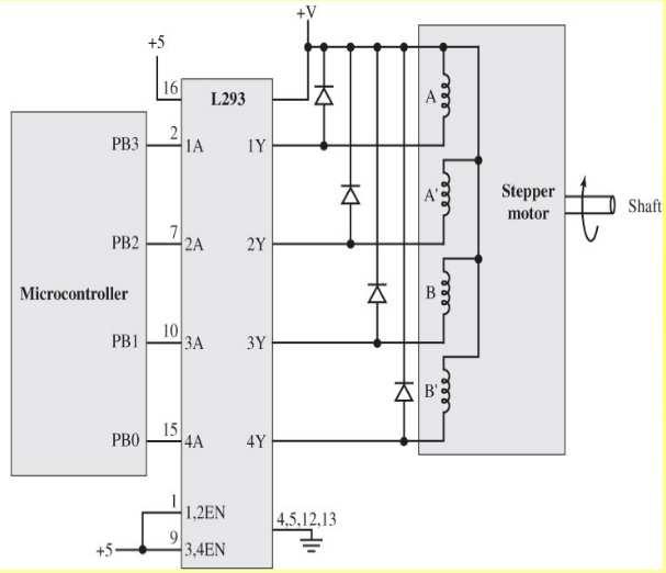
5 Chris J. Myers (Lecture 15: Relays and Motors) ECE/CS 5780/6780: Embedded System Design 25 / 38 Chris J. Myers (Lecture 15: Relays and Motors) ECE/CS 5780/6780: Embedded System Design 26 / 38 Bipolar Stepper Motor Interface Chris J. Myers (Lecture 15: Relays and Motors) ECE/CS 5780/6780: Embedded System Design 27 / 38 Chris J. Myers (Lecture 15: Relays and Motors) ECE/CS 5780/6780: Embedded System Design 28 / 38 Another Bipolar Stepper Motor Interface Unipolar Stepper Motor Interface Chris J. Myers (Lecture 15: Relays and Motors) ECE/CS 5780/6780: Embedded System Design 29 / 38 Chris J. Myers (Lecture 15: Relays and Motors) ECE/CS 5780/6780: Embedded System Design 30 / 38
6 Slip A slip is when computer issues a sequence change, but the motor does not move. Occurs if load on shaft exceeds available torque of motor. Can also occur if computer changes output too fast. If initial shaft angle known and motor never slips, computer can control shaft angle and speed without position sensor. Chris J. Myers (Lecture 15: Relays and Motors) ECE/CS 5780/6780: Embedded System Design 31 / 38 Chris J. Myers (Lecture 15: Relays and Motors) ECE/CS 5780/6780: Embedded System Design 32 / 38 Data Structures to Control Stepper Motor Ritual to Control Stepper Motor const struct State{ unsigned char Out; // Output const struct State *Next[2]; // CW/CCW ; typedef struct State StateType; typedef StateType *StatePtr; #define clockwise 0 // Next index #define counterclockwise 1 // Next index StateType fsm[4]={ {10,{&fsm[1],&fsm[3], { 9,{&fsm[2],&fsm[0], { 5,{&fsm[3],&fsm[1], { 6,{&fsm[0],&fsm[2]; unsigned char Pos; // between 0 and 199 StatePtr Pt; // Current State void Init(void){ Pos = 0; Pt = &fsm[0]; DDRB = 0xFF; Chris J. Myers (Lecture 15: Relays and Motors) ECE/CS 5780/6780: Embedded System Design 33 / 38 Chris J. Myers (Lecture 15: Relays and Motors) ECE/CS 5780/6780: Embedded System Design 34 / 38 Helper Functions to Control Stepper Motor void CW(void){ Pt = Pt->Next[clockwise]; // circular PORTB = Pt->Out; // step motor if(pos==199){ // shaft angle Pos = 0; // reset else{ Pos++; // CW void CCW(void){ Pt = Pt->Next[counterclockwise]; PORTB = Pt->Out; // step motor if(pos==0){ // shaft angle Pos = 199; // reset else{ Pos--; // CCW Chris J. Myers (Lecture 15: Relays and Motors) ECE/CS 5780/6780: Embedded System Design 35 / 38 High-Level Control of Stepper Motor void Seek(unsigned char desired){ short CWsteps; if((cwsteps=desired-pos)<0){ CWsteps+=200; // CW steps is 0 to 199 if(cwsteps>100){ while(desired!=pos){ CCW(); else{ while(desired!=pos){ CW(); Chris J. Myers (Lecture 15: Relays and Motors) ECE/CS 5780/6780: Embedded System Design 36 / 38
 ECE/CS 5780/6780: Embedded System Design 37 / 38 Chris J.")
7 Stepper Motor as Shaft Position Sensor Timing of Stepper Motor as Shaft Position Sensor Chris J. Myers (Lecture 15: Relays and Motors) ECE/CS 5780/6780: Embedded System Design 37 / 38 Chris J. Myers (Lecture 15: Relays and Motors) ECE/CS 5780/6780: Embedded System Design 38 / 38
Page 1. Relays. Poles and Throws. Relay Types. Common embedded system problem CS/ECE 6780/5780. Al Davis. Terminology used for switches
 Relays CS/ECE 6780/5780 Al Davis Today s topics: Relays & Motors prelude to 5780 Lab 9 Common embedded system problem digital control: relatively small I & V levels controlled device requires significantly
L E C T U R E R, E L E C T R I C A L A N D M I C R O E L E C T R O N I C E N G I N E E R I N G
 P R O F. S L A C K L E C T U R E R, E L E C T R I C A L A N D M I C R O E L E C T R O N I C E N G I N E E R I N G G B S E E E @ R I T. E D U B L D I N G 9, O F F I C E 0 9-3 1 8 9 ( 5 8 5 ) 4 7 5-5 1 0
EEE3410 Microcontroller Applications Department of Electrical Engineering Lecture 11 Motor Control
 EEE34 Microcontroller Applications Department of Electrical Engineering Lecture Motor Control Week 3 EEE34 Microcontroller Applications In this Lecture. Interface 85 with the following output Devices Optoisolator
Experiment (1) Principles of Switching
 Principles of Switching") Experiment (1) Principles of Switching Introduction When you use microcontrollers, sometimes you need to control devices that requires more electrical current than a microcontroller can supply; for this,
Experiment (1) Principles of Switching Introduction When you use microcontrollers, sometimes you need to control devices that requires more electrical current than a microcontroller can supply; for this,
Assembly Language. Topic 14 Motion Control. Stepper and Servo Motors
 Assembly Language Topic 14 Motion Control Stepper and Servo Motors Objectives To gain an understanding of the operation of a stepper motor To develop a means to control a stepper motor To gain an understanding
MICROCONTROLLERS Stepper motor control with Sequential Logic Circuits
 PH-315 MICROCONTROLLERS Stepper motor control with Sequential Logic Circuits Portland State University Summary Four sequential digital waveforms are used to control a stepper motor. The main objective
MOSFET as a Switch. MOSFET Characteristics Curves
 MOSFET as a Switch MOSFET s make very good electronic switches for controlling loads and in CMOS digital circuits as they operate between their cut-off and saturation regions. We saw previously, that the
THE UNIVERSITY OF BRITISH COLUMBIA. Department of Electrical and Computer Engineering. EECE 365: Applied Electronics and Electromechanics
 THE UNIVERSITY OF BRITISH COLUMBIA Department of Electrical and Computer Engineering EECE 365: Applied Electronics and Electromechanics Final Exam / Sample-Practice Exam Spring 2008 April 23 Topics Covered:
2.017 DESIGN OF ELECTROMECHANICAL ROBOTIC SYSTEMS Fall 2009 Lab 4: Motor Control. October 5, 2009 Dr. Harrison H. Chin
 2.017 DESIGN OF ELECTROMECHANICAL ROBOTIC SYSTEMS Fall 2009 Lab 4: Motor Control October 5, 2009 Dr. Harrison H. Chin Formal Labs 1. Microcontrollers Introduction to microcontrollers Arduino microcontroller
ECET 211 Electric Machines & Controls Lecture 4-2 Motor Control Devices: Lecture 4 Motor Control Devices
 ECET 211 Electric Machines & Controls Lecture 4-2 Motor Control Devices: Part 3. Sensors, Part 4. Actuators Text Book: Electric Motors and Control Systems, by Frank D. Petruzella, published by McGraw Hill,
EM-100 Controller. Installation Precautions. July 2016
 EM-100 Controller Installation Precautions July 2016 Table of Contents 1 Overview... 3 2 The Issue... 3 3 Configuration Tutorial... 3 3.1 Working Principle... 3 3.2 Design... 5 3.3 Induction at the Opening
ECET 211 Electrical Machines and Controls
 ECET 211 Electrical Machines and Controls 2016/4/27 Class Review and Wrapping Up Comprehensive Exam, Friday, 1:00-3:00 PM, May 6, 2016 Close books/allow 1-page (8 x 11 and ½) hand-written review note,
EXPERIMENT 6: Advanced I/O Programming
 EXPERIMENT 6: Advanced I/O Programming Objectives: To familiarize students with DC Motor control and Stepper Motor Interfacing. To utilize MikroC and MPLAB for Input Output Interfacing and motor control.
Real Time Embedded Systems. Lecture 1 January 17, 2012
 Electric Motors Real Time Embedded Systems www.atomicrhubarb.com/embedded Lecture 1 January 17, 2012 Topic Warning! This is a work in progress. Watch out for sharp corners and slippery surfaces Motors
A COMPARISON STUDY OF THE COMMUTATION METHODS FOR THE THREE-PHASE PERMANENT MAGNET BRUSHLESS DC MOTOR
 A COMPARISON STUDY OF THE COMMUTATION METHODS FOR THE THREE-PHASE PERMANENT MAGNET BRUSHLESS DC MOTOR Shiyoung Lee, Ph.D. Pennsylvania State University Berks Campus Room 120 Luerssen Building, Tulpehocken
Implementation Of Solid State Relays For Power System Protection
 Implementation Of Solid State Relays For Power System Protection Nidhi Verma, Kartik Gupta, Sheila Mahapatra ABSTRACT: This paper provides the implementation of solid state relays for enhancement of power
Application Note. 3-Phase Brushless DC Motor Control with Hall Sensors AN-CM-244
 Application Note 3-Phase Brushless DC Motor Control with Hall AN-CM-244 Abstract This application note describes how to control a 3-phase brushless DC motor using a GreenPAK. This application note comes
Actuators. EECS461, Lecture 5, updated September 16,
 Actuators The other side of the coin from sensors... Enable a microprocessor to modify the analog world. Examples: - speakers that transform an electrical signal into acoustic energy (sound) - remote control
Administrative Notes. DC Motors; Torque and Gearing; Encoders; Motor Control. Today. Early DC Motors. Friday 1pm: Communications lecture
 At Actuation: ti DC Motors; Torque and Gearing; Encoders; Motor Control RSS Lecture 3 Wednesday, 11 Feb 2009 Prof. Seth Teller Administrative Notes Friday 1pm: Communications lecture Discuss: writing up
Basic NC and CNC. Dr. J. Ramkumar Professor, Department of Mechanical Engineering Micro machining Lab, I.I.T. Kanpur
 Basic NC and CNC Dr. J. Ramkumar Professor, Department of Mechanical Engineering Micro machining Lab, I.I.T. Kanpur Micro machining Lab, I.I.T. Kanpur Outline 1. Introduction to CNC machine 2. Component
Chapter 7: The motors of the robot
 Chapter 7: The motors of the robot Learn about different types of motors Learn to control different kinds of motors using open-loop and closedloop control Learn to use motors in robot building 7.1 Introduction
combine regular DC-motors with a gear-box and an encoder/potentiometer to form a position control loop can only assume a limited range of angular
 Embedded Control Applications II MP10-1 Embedded Control Applications II MP10-2 week lecture topics 10 Embedded Control Applications II - Servo-motor control - Stepper motor control - The control of a
DECEMBER 2014 Level 2 Certificate/Diploma in Engineering (IVQ) Principles of electrical and electronics technology
 Principles of electrical and electronics technology") *28502561214* 2850-256 DECEMBER 2014 Level 2 Certificate/Diploma in Engineering (IVQ) Principles of electrical and electronics technology Tuesday 11 December 2014 09:30 11:30 You should have the following
*28502561214* 2850-256 DECEMBER 2014 Level 2 Certificate/Diploma in Engineering (IVQ) Principles of electrical and electronics technology Tuesday 11 December 2014 09:30 11:30 You should have the following
Application Note AN-3006 Optically Isolated Phase Controlling Circuit Solution
 www.fairchildsemi.com Application Note AN-3006 Optically Isolated Phase Controlling Circuit Solution Introduction Optocouplers simplify logic isolation from the ac line, power supply transformations, and
Computer Numeric Control
 Computer Numeric Control TA202A 2017-18(2 nd ) Semester Prof. J. Ramkumar Department of Mechanical Engineering IIT Kanpur Computer Numeric Control A system in which actions are controlled by the direct
Relay Types and Applications Dr. Sasidharan Sreedharan
 O&M of Protection System and Relay Coordination Relay Types and Applications Dr. Sasidharan Sreedharan www.sasidharan.webs.com Detailed Schedule 2 SIMPLE RELAY Magnitude Rate of Change Phase Angle Direction
INTEGRATED CIRCUITS. AN1221 Switched-mode drives for DC motors. Author: Lester J. Hadley, Jr.
 INTEGRATED CIRCUITS Author: Lester J. Hadley, Jr. 1988 Dec Author: Lester J. Hadley, Jr. ABSTRACT The purpose of this paper is to demonstrate the use of integrated switched-mode controllers, generally
Chapter 5 Electric Logic Sensors and Actuators
 Chapter 5: Electric logic sensors and actuators -IE337 Chapter 5 Electric Logic Sensors and Actuators 1 5.1 Introduction to Electric Logic Sensors and Actuators Electric sensors and actuators can be classified
Actuators in Automatic Control System
 Actuators in Automatic Control System Measurement & Control Systems Transducers Measurement Process Actuators Data processing Requirement analyses Decision making Control actions CONTROL action requires
Lock Cracker S. Lust, E. Skjel, R. LeBlanc, C. Kim
 Lock Cracker S. Lust, E. Skjel, R. LeBlanc, C. Kim Abstract - This project utilized Eleven Engineering s XInC2 development board to control several peripheral devices to open a standard 40 digit combination
3. What is the difference between Switched Reluctance motor and variable reluctance stepper motor?(may12)
") EE6703 SPECIAL ELECTRICAL MACHINES UNIT III SWITCHED RELUCTANCE MOTOR PART A 1. What is switched reluctance motor? The switched reluctance motor is a doubly salient, singly excited motor. This means that
EE6703 SPECIAL ELECTRICAL MACHINES UNIT III SWITCHED RELUCTANCE MOTOR PART A 1. What is switched reluctance motor? The switched reluctance motor is a doubly salient, singly excited motor. This means that
Stepper Motors and Control Part I - Unipolar Stepper Motor and Control (c) 1999 by Rustle Laidman, All Rights Reserved
 1999 by Rustle Laidman, All Rights Reserved") Copyright Notice: (C) June 2000-2008 by Russell Laidman. All Rights Reserved. ------------------------------------------------------------------------------------ The material contained in this project,
Copyright Notice: (C) June 2000-2008 by Russell Laidman. All Rights Reserved. ------------------------------------------------------------------------------------ The material contained in this project,
1 Select a convenient capacitance value for the two capacitors. 2 Calculate the three resistor values for x = 1/(2πf 0 C).
.") Simple Active Filter ECE/CS 5780/6780: Embedded System Design Chris J. Myers Lecture 18: Analog Filters and DACs Chris J. Myers (Lecture 18: Filters/DACs) ECE/CS 5780/6780: Embedded System Design 1 / 35
Simple Active Filter ECE/CS 5780/6780: Embedded System Design Chris J. Myers Lecture 18: Analog Filters and DACs Chris J. Myers (Lecture 18: Filters/DACs) ECE/CS 5780/6780: Embedded System Design 1 / 35
Stepper Motors in C. Unipolar (5 lead) stepper motorr. $1.95 from 100 steps per rotation. 24V / 160mA / 600 gm cm holding 160mA
 stepper motorr. $1.95 from 100 steps per rotation. 24V / 160mA / 600 gm cm holding 160mA") U tepper Motors ugust 22, 2017 tepper Motors in Unipolar (5 lead) stepper motorr. $1.95 from www.mpja.com 100 steps per rotation. 24V / 160m / 600 gm cm holding torque @ 160m stepper motor is a digital
U tepper Motors ugust 22, 2017 tepper Motors in Unipolar (5 lead) stepper motorr. $1.95 from www.mpja.com 100 steps per rotation. 24V / 160m / 600 gm cm holding torque @ 160m stepper motor is a digital
PART 2 - ACTUATORS. 6.0 Stepper Motors. 6.1 Principle of Operation
 6.1 Principle of Operation PART 2 - ACTUATORS 6.0 The actuator is the device that mechanically drives a dynamic system - Stepper motors are a popular type of actuators - Unlike continuous-drive actuators,
Step Motor Controller I. Introduction II. Step Motor Basics
 Step Motor Controller Objectives: --Gain familiarity with step motors --Build and understand a simple stepper motor controller --Learn the function of a shaft encoder --Design a circuit to use the motor,
DC-Motor Driver circuits
 DC-Mot May 19, 2012 Why is there a need for a motor driver circuit? Normal DC gear-head motors requires current greater than 250mA. ICs like 555 timer, ATmega Microcontroller, 74 series ICs cannot supply
M.Kaliamoorthy and I.Gerald PSNACET/EEE CHAPTER 2 STEPPER MOTORS
 2.1.General Lecture Notes M.Kaliamoorthy and I.Gerald PSNACET/EEE CHAPTER 2 STEPPER MOTORS Stepper motors are electromagnetic incremental devices that convert electric pulses to shaft motion (rotation).
Experiment#6: Speaker Control
 Experiment#6: Speaker Control I. Objectives 1. Describe the operation of the driving circuit for SP1 speaker. II. Circuit Description The circuit of speaker and driver is shown in figure# 1 below. The
Know about. Different Types of Relays
 Know about Different Types of Relays By Contents What Is a Relay and How It Works? 1 Applications of Relays 2 Classification of Relays 3 1. Electromagnetic Relays 3 1.1 Attraction Type Electromagnetic
ECET 211 Electric Machines & Controls Lecture 9-1 Adjustable-Speed Drives and PLC Installations (1 of 2)
") ECET 211 Electric Machines & Controls Lecture 9-1 Adjustable-Speed Drives (1 of 2) Text Book: Electric Motors and Control Systems, by Frank D. Petruzella, published by McGraw Hill, 2015. Paul I-Hai Lin,
ECET 211 Electric Machines & Controls Lecture 9-1 Adjustable-Speed Drives (1 of 2) Text Book: Electric Motors and Control Systems, by Frank D. Petruzella, published by McGraw Hill, 2015. Paul I-Hai Lin,
Half stepping techniques
 Half stepping techniques By operating a stepper motor in half stepping mode it is possible to improve system performance in regard to higher resolution and reduction of resonances. It is also possible
815-BR SERVO AMPLIFIER FOR BRUSH SERVOMOTORS
 815-BR SERVO AMPLIFIER FOR BRUSH SERVOMOTORS USER GUIDE September 2004 Important Notice This document is subject to the following conditions and restrictions: This document contains proprietary information
School of Engineering Mechatronics Engineering Department. Experim. ment no. 1
 University of Jordan School of Engineering Mechatronics Engineering Department 2010 Mechatronics System Design Lab Experim ment no. 1 PRINCIPLES OF SWITCHING Copyrights' are held by : Eng. Ala' Bata &
Robot Actuators. Motors and Control. Stepper Motor Basics. Increased Resolution. Stepper motors. DC motors AC motors. Physics review: Nature is lazy.
 obot Actuators tepper motors Motors and Control DC motors AC motors Physics review: ature is lazy. Things seek lowest energy states. iron core vs. magnet magnetic fields tend to line up Electric fields
1525-BRS INFORMATION MANUAL SERV O D YN A M ICS. D y n ad r iv e Ave Crocker Suite 10 Valencia, CA
 28231 Ave Crocker Suite 10 Valencia, CA 91355 818-700-8600 Servodynamics.com INFORMATION MANUAL 1525-BRS SERV O D YN A M ICS U SA www.servodynamics.com D y n ad r iv e Bru sh INDEX Page INTRODUCTION 2
PLC BASED RAILWAY LEVEL CROSSING GATE CONTROL
 PLC BASED RAILWAY LEVEL CROSSING GATE CONTROL R.Gopinathan *1 and B.Sivashankar #2 * Assistant professor, Mechatronics, SNS College of Technology, Coimbatore,India. # UG scholar, Mechatronics, SNS College
Stepper motors. Resources and methods for learning about these subjects (list a few here, in preparation for your research):
:") Stepper motors This worksheet and all related files are licensed under the Creative Commons Attribution License, version 1.0. To view a copy of this license, visit http://creativecommons.org/licenses/by/1.0/,
Stepper motors This worksheet and all related files are licensed under the Creative Commons Attribution License, version 1.0. To view a copy of this license, visit http://creativecommons.org/licenses/by/1.0/,
ADC Parameters. ECE/CS 5780/6780: Embedded System Design. Common Encoding Schemes. Two-Bit Flash ADC. Sixteen-Bit Dual Slope ADC
 ADC Parameters ECE/CS 5780/6780: Embedded System Design Chris J. Myers Lecture 19: Analog-to-Digital Conversion Precision is number of distinguishable ADC inputs. Range is maximum and minimum ADC inputs.
TA7259P, TA7259F/FG TA7259P/F/FG 3-PHASE BRUSHLESS DC MOTOR DRIVER IC FEATURES TOSHIBA BIPOLAR LINEAR INTEGRATED CIRCUIT SILICON MONOLITHIC
 TOSHIBA BIPOLAR LINEAR INTEGRATED CIRCUIT SILICON MONOLITHIC TA7259P, TA7259F/FG TA7259P/F/FG 3-PHASE BRUSHLESS DC MOTOR DRIVER IC The TA7259P/F/FG is a 3 phase Bi-directional motor driver IC. It designed
DynaDrive INFORMATION MANUAL SDFP(S)
") DynaDrive INFORMATION MANUAL SDFP(S)1525-17 SERVO DYNAMICS CORP. 28231 Avenue Crocker, Santa Clarita, CA. 91355 (818) 700-8600 Fax (818) 718-6719 www.servodynamics.com INDEX Page INTRODUCTION 2 ELECTRICAL
DynaDrive INFORMATION MANUAL SDFP(S)1525-17 SERVO DYNAMICS CORP. 28231 Avenue Crocker, Santa Clarita, CA. 91355 (818) 700-8600 Fax (818) 718-6719 www.servodynamics.com INDEX Page INTRODUCTION 2 ELECTRICAL
Modeling, Simulation and Implementation of Speed Control of DC Motor Using PIC 16F877A
 Modeling, Simulation and Implementation of Speed Control of DC Motor Using PIC 16F877A Payal P.Raval 1, Prof.C.R.mehta 2 1 PG Student, Electrical Engg. Department, Nirma University, SG Highway, Ahmedabad,
ECE 4510/5530 Microcontroller Applications Week 13
 ECE 4510/5530 Microctroller Applicatis Week 13 Dr. Bradley J. Bazuin Associate Professor Department of Electrical and Computer Engineering College of Engineering and Applied ciences General Informati More
Inductance. Chapter 30. PowerPoint Lectures for University Physics, Thirteenth Edition Hugh D. Young and Roger A. Freedman. Lectures by Wayne Anderson
 Chapter 30 Inductance PowerPoint Lectures for University Physics, Thirteenth Edition Hugh D. Young and Roger A. Freedman Lectures by Wayne Anderson Goals for Chapter 30 To learn how current in one coil
Controlling Stepper Motors Using the Power I/O Wildcard
 Mosaic Industries Controlling Stepper Motors Using the Power I/O Wildcard APPLICATION NOTE MI-AN-072 2005-09-15 pkc The Mosaic Stepper Motor The Mosaic stepper motor is a four-phase, unipolar stepping
REQUIRED SKILLS AND KNOWLEDGE UEENEEG101A. Electromagnetic devices and circuits. Topic and Description NIDA Lesson CARD # Magnetism encompassing:
 REQUIRED SKILLS AND KNOWLEDGE UEENEEG101A KS01-EG101A Electromagnetic devices and circuits T1 Magnetism encompassing: Topic and Description NIDA Lesson CARD # magnetic field pattern of bar and horse-shoe
BLOCK DIAGRAM OF THE UC3625
 U-115 APPLICATION NOTE New Integrated Circuit Produces Robust, Noise Immune System For Brushless DC Motors Bob Neidorff, Unitrode Integrated Circuits Corp., Merrimack, NH Abstract A new integrated circuit
PREREQUISITES: MODULE 10: MICROCONTROLLERS II; MODULE 14: DISCRETE COMPONENTS. MODULE 13 (SENSORS) WOULD ALSO BE HELPFUL.
 WOULD ALSO BE HELPFUL.") ELECTROMECHANICAL SYSTEMS PREREQUISITES: MODULE 10: MICROCONTROLLERS II; MODULE 14: DISCRETE COMPONENTS. MODULE 13 (SENSORS) WOULD ALSO BE HELPFUL. OUTLINE OF MODULE 17: What you will learn about in this
ELECTROMECHANICAL SYSTEMS PREREQUISITES: MODULE 10: MICROCONTROLLERS II; MODULE 14: DISCRETE COMPONENTS. MODULE 13 (SENSORS) WOULD ALSO BE HELPFUL. OUTLINE OF MODULE 17: What you will learn about in this
USING THE L6204, A BIPOLAR STEPPER AND DC MOTOR DRIVER IN BCD TECHNOLOGY
 USING THE L6204, A BIPOLAR STEPPER AND DC MOTOR DRIVER IN BCD TECHNOLOGY by E Balboni Containing two H-bridge drivers, the L6204 is a compact and simple solution for driving two-phase bipolar stepper motors
M.D. Singh J.G. Joshi MECHATRONICS
 M.D. Singh J.G. Joshi MECHATRONICS MECHATRONICS MECHATRONICS M.D. SINGH Formerly Principal Sagar Institute of Technology and Research Bhopal J.G. JOSHI Lecturer Department of Electronics and Telecommunication
Job Sheet 2 Servo Control
 Job Sheet 2 Servo Control Electrical actuators are replacing hydraulic actuators in many industrial applications. Electric servomotors and linear actuators can perform many of the same physical displacement
DC Motor Speed Control using PID Controllers
 "EE 616 Electronic System Design Course Project, EE Dept, IIT Bombay, November 2009" DC Motor Speed Control using PID Controllers Nikunj A. Bhagat (08307908) nbhagat@ee.iitb.ac.in, Mahesh Bhaganagare (CEP)
Motors and Servos Part 2: DC Motors
 Motors and Servos Part 2: DC Motors Back to Motors After a brief excursion into serial communication last week, we are returning to DC motors this week. As you recall, we have already worked with servos
SECTION 3 BASIC AUTOMATIC CONTROLS UNIT 12 BASIC ELECTRICITY AND MAGNETISM. Unit Objectives. Unit Objectives 2/29/2012
 SECTION 3 BASIC AUTOMATIC CONTROLS UNIT 12 BASIC ELECTRICITY AND MAGNETISM Unit Objectives Describe the structure of an atom. Identify atoms with a positive charge and atoms with a negative charge. Explain
Sensorless control of BLDC motor based on Hysteresis comparator with PI control for speed regulation
 Sensorless control of BLDC motor based on Hysteresis comparator with PI control for speed regulation Thirumoni.T 1,Femi.R 2 PG Student 1, Assistant Professor 2, Department of Electrical and Electronics
Application Note # 5438
 Application Note # 5438 Electrical Noise in Motion Control Circuits 1. Origins of Electrical Noise Electrical noise appears in an electrical circuit through one of four routes: a. Impedance (Ground Loop)
Lecture 6. Interfacing Digital and Analog Devices to Arduino. Intro to Arduino
 Lecture 6 Interfacing Digital and Analog Devices to Arduino. Intro to Arduino PWR IN USB (to Computer) RESET SCL\SDA (I2C Bus) POWER 5V / 3.3V / GND Analog INPUTS Digital I\O PWM(3, 5, 6, 9, 10, 11) Components
6.111 Lecture # 19. Controlling Position. Some General Features of Servos: Servomechanisms are of this form:
 6.111 Lecture # 19 Controlling Position Servomechanisms are of this form: Some General Features of Servos: They are feedback circuits Natural frequencies are 'zeros' of 1+G(s)H(s) System is unstable if
Power systems Protection course
 Al-Balqa Applied University Power systems Protection course Department of Electrical Energy Engineering 1 Part 5 Relays 2 3 Relay Is a device which receive a signal from the power system thought CT and
87000 Series Size 34 Hybrid Linear Actuators
 87000 Series Single Stack Stepper Motor Linear Actuators 87000 Series Hybrid Linear Actuators Our largest, most powerful linear actuator incorporates the same precision, high performance and durable patented
Shaft encoders are digital transducers that are used for measuring angular displacements and angular velocities.
 Shaft Encoders: Shaft encoders are digital transducers that are used for measuring angular displacements and angular velocities. Encoder Types: Shaft encoders can be classified into two categories depending
9/28/2010. Chapter , The McGraw-Hill Companies, Inc.
 Chapter 4 Sensors are are used to detect, and often to measure, the magnitude of something. They basically operate by converting mechanical, magnetic, thermal, optical, and chemical variations into electric
Brushed DC Motor PWM Speed Control with the NI myrio, Optical Encoder, and H-Bridge
 Brushed DC Motor PWM Speed Control with the NI myrio, Optical Encoder, and H-Bridge Motor Controller Brushed DC Motor / Encoder System K. Craig 1 Gnd 5 V OR Gate H-Bridge 12 V Bypass Capacitors Flyback
Ledex Drive Electronics and Coil Suppressors
 Ledex and Coil Suppressors Ledex Coil Suppressors A voltage is generated by a changing magnetic field in proximity to a current-carrying member. The equation E = -N dø /dt, describes this by saying that
Designing With Motion Handbook
 Designing With Motion Handbook Chapter IV Brush There are many different types of systems that can use manyy different types of motor such as BLDC, Brush, Stepper, Hollow Core, etc. But for this write-up,
High-Voltage High-Current Stepper Motor Driver IK6019A TECHNICAL DATA
 TECHNICAL DATA High-Voltage High-Current Stepper Motor Driver IK6019A FEATURES Eight Power Output LDMOS Transistors Driving Dual Stepping Motor Output Current 250mA per Driver Output Voltage 24V Reset
Size 23 Double Stack External Linear Size 23 Double Stack. 57M4 n n n n n n. 57L4 n n n n n n. E57M4 n n n n n n. Bipolar 5 VDC 12 VDC 2.
 HAYD: 0 756 7 57000 Series: Double Stack Stepper Motor Linear Actuator Haydon 57000 Series Double Stack hybrid linear actuators deliver greater performance in a compact size. The various patented designs
Feedback Devices. By John Mazurkiewicz. Baldor Electric
 Feedback Devices By John Mazurkiewicz Baldor Electric Closed loop systems use feedback signals for stabilization, speed and position information. There are a variety of devices to provide this data, such
ORIENTAL MOTOR GENERAL CATALOG
 ORIENTL MOTOR GENERL CTLOG STEPPING MOTORS 5-PHSE STEPPING MOTOR ND MICROSTEP DRIVER PCKGE RFK Features B-64 Specifications B-67 Speed vs.torque Characteristics B-68 Dimensions B-69 List of Motor and Combinations
Calhoon MEBA Engineering School. Study Guide for Proficiency Testing Industrial Electronics
 Calhoon MEBA Engineering School Study Guide for Proficiency Testing Industrial Electronics January 0. Which factors affect the end-to-end resistance of a metallic conductor?. A waveform shows three complete
Tektronix AFG10022 Function Generator. Coming soon to B10: Sin, Square, Ramp, Swept, Arbitrary, Noise. Linear Actuators. Non-magnetized iron plunger
 4/19/18 Tektronix AFG10022 Function Generator Coming soon to B10: Sin, Square, Ramp, Swept, Arbitrary, Noise 508 Linear Actuators Solenoids (stationary coil) Non-magnetized iron plunger Iron always pulled
AN Industrial Stepper Motor Driver. Application Note Abstract. Introduction. Stepper Motor Control Method
 Industrial Stepper Motor Driver AN43679 Author: Dino Gu, Bill Jiang, Jemmey Huang Associated Project: Yes Associated Part Family: CY8C27x43, CY8C29x66 GET FREE SAMPLES HERE Software Version: PSoC Designer
Electronic Speed Controls and RC Motors
 Electronic Speed Controls and RC Motors ESC Power Control Modern electronic speed controls regulate the electric power applied to an electric motor by rapidly switching the power on and off using power
Introduction to Arduino HW Labs
 Introduction to Arduino HW Labs In the next six lab sessions, you ll attach sensors and actuators to your Arduino processor This session provides an overview for the devices LED indicators Text/Sound Output
Pulse Width Modulation (PWM) and Relays
 and Relays") Pulse Width Modulation (PWM) and Relays Introduction Efficient energy management is one of the main goals in automotive industry Regulating actuators by Pulse Width Modulation (PWM) is a widespread means
Pulse Width Modulation (PWM) and Relays Introduction Efficient energy management is one of the main goals in automotive industry Regulating actuators by Pulse Width Modulation (PWM) is a widespread means
Open Loop Speed Control of Brushless DC Motor
 Open Loop Speed Control of Brushless DC Motor K Uday Bhargav 1, Nayana T N 2 PG Student, Department of Electrical & Electronics Engineering, BNMIT, Bangalore, Karnataka, India 1 Assistant Professor, Department
DISCUSSION OF FUNDAMENTALS
 Unit 4 AC s UNIT OBJECTIVE After completing this unit, you will be able to demonstrate and explain the operation of ac induction motors using the Squirrel-Cage module and the Capacitor-Start Motor module.
28000 Series Size 11 Double Stack Hybrid Linear Actuators
 28000 Series Double Stack Stepper Motor Linear Actuators 28000 Series Double Stack Hybrid Linear Actuators Enhanced performance in motion control The 28000 Series is available in a wide variety of resolutions
Electric Power Systems 2: Generators, Three-phase Power, and Power Electronics
 15-830 Electric Power Systems 2: Generators, Three-phase Power, and Power Electronics J. Zico Kolter October 9, 2012 1 Generators Basic AC Generator Rotating Magnet Loop of Wire 2 Generator operation Voltage
AP Physics Electricity and Magnetism #7 Inductance
 Name Period AP Physics Electricity and Magnetism #7 Inductance Dr. Campbell 1. Do problems Exercise B page 589 and problem 2, 3, 8, 9 page 610-1. Answers at the end of the packet. 2. A 20-turn wire coil
Speed Control of BLDC Motor Using FPGA
 Speed Control of BLDC Motor Using FPGA Jisha Kuruvilla 1, Basil George 2, Deepu K 3, Gokul P.T 4, Mathew Jose 5 Assistant Professor, Dept. of EEE, Mar Athanasius College of Engineering, Kothamangalam,
ME 2110 Controller Box Manual. Version 2.3
 ME 2110 Controller Box Manual Version 2.3 I. Introduction to the ME 2110 Controller Box A. The Controller Box B. The Programming Editor & Writing PBASIC Programs C. Debugging Controller Box Problems II.
Figure 1.1 Mechatronic system components (p. 3)
") Figure 1.1 Mechatronic system components (p. 3) Example 1.2 Measurement System Digital Thermometer (p. 5) Figure 2.2 Electric circuit terminology (p. 13) Table 2.2 Resistor color band codes (p. 18) Figure
Figure 1.1 Mechatronic system components (p. 3) Example 1.2 Measurement System Digital Thermometer (p. 5) Figure 2.2 Electric circuit terminology (p. 13) Table 2.2 Resistor color band codes (p. 18) Figure
Speed Control of DC Motor Using Microcontroller
 2015 IJSRST Volume 1 Issue 2 Print ISSN: 2395-6011 Online ISSN: 2395-602X Themed Section: Science Speed Control of DC Motor Using Microcontroller Katke S.P *1, Rangdal S.M 2 * 1 Electrical Department,
Introduction to the ME2110 Kit. Controller Box Electro Mechanical Actuators & Sensors Pneumatics
 Introduction to the ME2110 Kit Controller Box Electro Mechanical Actuators & Sensors Pneumatics Features of the Controller Box BASIC Stamp II-SX microcontroller Interfaces with various external devices
5-Phase Stepping Motor and Microstep Driver Package
 ORIENTAL MOTOR GENERAL CATALOGUE Motor and Microstep Driver Package RFK Features B-154 Specifications B-157 Speed - Torque Characteristics B-158 Dimensions B-159 List of motor and Driver Combinations B-16
Step vs. Servo Selecting the Best
 Step vs. Servo Selecting the Best Dan Jones Over the many years, there have been many technical papers and articles about which motor is the best. The short and sweet answer is let s talk about the application.
The Fundamental Characteristics of Novel Switched Reluctance Motor with Segment Core Embedded in Aluminum Rotor Block
 58 Journal of Electrical Engineering & Technology, Vol. 1, No. 1, pp. 58~62, 2006 The Fundamental Characteristics of Novel Switched Reluctance Motor with Segment Core Embedded in Aluminum Rotor Block Jun
BLOCK DIAGRAM OF THE UC3625
 U-115 APPLICATION NOTE New Integrated Circuit Produces Robust, Noise Immune System For Brushless DC Motors Bob Neidorff, Unitrode Integrated Circuits Corp., Merrimack, NH Abstract A new integrated circuit
Electronic Components (Elements)
") Lecture_3 Electronic Components (Elements) Instructor: IBRAHIM ABU-ISBEIH 25 July 2011 Reverse Engineering 1 Objectives: After completing this class, you will be able to identify the most commonly used
Lecture_3 Electronic Components (Elements) Instructor: IBRAHIM ABU-ISBEIH 25 July 2011 Reverse Engineering 1 Objectives: After completing this class, you will be able to identify the most commonly used