MAHARASHTRA STATE ELECTRICITY DISTRIBUTION COMPANY LTD. TECHNICAL SPECIFICATION FOR. 36 kv (PROTECTION CUM METERING) INSTRUMENT TRANSFORMERS
|
|
|
- Everett Morgan
- 6 years ago
- Views:
Transcription
1 MAHARASHTRA STATE ELECTRICITY DISTRIBUTION COMPANY LTD. TECHNICAL SPECIFICATION FOR 36 kv (PROTECTION CUM METERING) INSTRUMENT TRANSFORMERS FOR VARIOUS SUBSTATIONS IN MAHARASHTRA {(SPECIFICATION NO.: DIST/ MM/I/ 36 kv CT & PT/2008/R1(030311)} Page 1 of 35
2 SCHEDULE ' A' (SPECIFICATION NO.: DIST/MM/I/ 36 kv CT & PT/2008/R1(030311) INDEX CLAUSE NO. PARTICULARS. PAGE. Specification Details 1.0 Scope Service Conditions Standards Principal Technical Parameters General technical requirements - Common for all Instrument 4-7 Transformers 5.2 General technical requirements for Current Transformer General technical requirements for Potential Transformer Type tests Acceptance and routine tests Inspection Qualifying requirements Quality assurance plan Performance Guarantee Documentation Packing and Forwarding Schedules Annexure 1 ANNEXURE-I 19 2 ANNEXURE-II-A & II-B 20 3 ANNEXURE-III-A ANNEXURE-III-B 24 5 ANNEXURE-IV ANNEXURE-V 27 Schedules Page 2 of 35
3 SCHEDULE ' A TECHNICAL SPECIFICATION FOR INSTRUMENT TRANSFORMERS (SPECIFICATION NO.: DIST/MM/I/ 36 kv CT & PT/2008/R1(030311) 1.0 SCOPE: 1.1 This specification covers design, manufacture, assembly, testing at manufacturer s works, packing and delivery of outdoor instrument transformers for protection and metering services in 33 kv Sub-stations in Maharashtra State (India). 1.2 It is not the intent to specify completely herein all details of the design and construction of equipments. However, the equipment shall conform in all respects to high standards of engineering, design and workmanship mentioned in clause 4.0 and shall be capable of performing in continuous commercial operation up to the supplier s guarantee in a manner acceptable to the purchaser, who will interpret the meanings of drawings and specification and shall have the power to reject any work or material which, in his judgment, is not in accordance therewith. 1.3 The equipments offered shall be complete with all components necessary for their effective and trouble free operation. Such components shall be deemed to be within the scope of supplier's supply irrespective of whether those are specifically brought out in this specification and / or the commercial order or not. 2.0 SERVICE CONDITIONS: 2.1 Equipment to be supplied against this specification shall be suitable for satisfactory continuous operation under the following tropical conditions Maximum ambient temperature in open air ( C): Maximum ambient temperature in shade ( C) Minimum temperature in shade( C): Relative humidity (%) 10 to Maximum annual rainfall (mm) Maximum wind pressure 150 (Kg/ Sqmtr.) Maximum altitude above mean sea level (Mtrs) Isoceraunic level (days/year) Seismic level (Horizontal acceleration) 0.3 g General nature of climate : Moderately hot and humid tropical climate, conducive to rust and fungus growth. Page 3 of 35
4 3.0 STANDARDS: Unless otherwise specified elsewhere in this specification, the rating, performance and testing of the instrument transformers and accessories shall conform to the latest revisions, of all relevant standards listed in Annexure-II (A & B). 4.0 PRINCIPAL TECHNICAL PARAMETERS: The Current transformers and Voltage transformers covered in this specification shall meet the technical requirements listed in Annexure IIIA & IIIB respectively. 5.0 GENERAL TECHNICAL REQUIREMENTS: 5.1 COMMON FOR ALL INSTRUMENT TRANSFORMERS: The insulation of the instrument transformers shall be so designed that the internal insulation shall have higher electrical withstand capability than the external insulation. The designed dielectrics withstand values of external and internal insulations shall be clearly brought out in the GTP (Guaranteed Technical particulars). The dielectric withstand values specified in this specification are meant for fully assembled instrument transformer. The temperature rise on any part of equipment shall not exceed the maximum temperature rise limits specified in annexure IV under the conditions specified there in PORCELAIN HOUSING: The porcelain housing shall be of a single piece construction without any joint or coupling.the housing shall be made of homogeneous, vitreous porcelain of high mechanical and dielectric strength. Glazing of porcelain shall be of uniform brown or dark brown colour with a smooth surface arranged to shed away rainwater or condensed water particles (fog). The profile of porcelain shall be aerodynamic type as per IEC The vertical clearance of porcelain housing shall be at least 450mm Details of attachment of metallic flanges to the porcelain for pressure release valve, and primary / secondary terminals shall be brought out in the offer METAL TANKS: The metal tanks shall have bare minimum number of welded joints so as Page 4 of 35
5 to minimize possible locations of oil leakage. The metal tanks shall be made out of mild steel. The thickness of the metal tank shall be more than 3.00 mm. Actual thickness provided shall be specified by the tenderer The bottom of the tank shall be adequately accessible for periodical maintenance of open surface SURFACE FINISH: The metal tanks shall be coated with at least two coats of zinc rich epoxy painting. All the ferrous hardware, exposed to atmosphere, shall be hot dip galvanized. All other fixing nuts, bolts, washers in the electrical current path shall be made out of stainless steel INSULATING OIL: Insulating oil required for first filling of the instrument transformer shall be covered in bidder's scope of supply. The oil shall meet the requirements of latest edition of IS PREVENTION OF OIL LEAKAGES & ENTRY OF MOISTURE: As specified elsewhere in this specification, the instrument transformer shall be guaranteed for a trouble free and maintenance - free performance for a period as specified. Therefore, the bidder shall ensure that the sealing of instrument transformer is properly achieved. In this connection the arrangement provided by the bidder at various locations including the following ones shall be described, supported by sectional drawings. i) Locations of emergence of primary and secondary terminals. ii) Interface between porcelain housing and metal tanks iii) Cover of the secondary terminal box Nuts and bolts or screws used for fixation of the interfacing porcelain bushings for taking out terminals shall be provided on flanges cemented to the bushings and not on the porcelain For gasket joints, wherever used nitrite butyl rubber gaskets shall be used. The gasket shall be fitted in properly machined groove with adequate space for accommodating the gasket under compression OIL LEVEL INDICATORS: For compensation of variation in volume of the oil due to temperature variation, nitrogen cushion or Stainless Steel bellows shall be used. Rubber diaphragms shall not be permitted for this purpose Instrument transformer provided with nitrogen cushion for Compensation Page 5 of 35
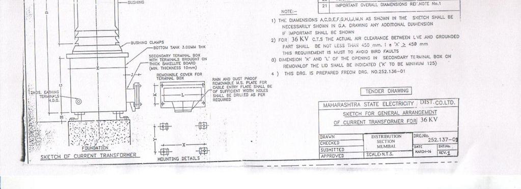
6 of oil volume variation shall be provided with prismatic type oil sight window at suitable location so that the oil level is clearly visible with naked eye to an observer standing at ground level. If metal bellow is used for the above purpose, a ground glass window shall be provided to monitor the position of metal bellow EARTHING: Metal tank of the instrument transformer shall be provided with two separate earthing terminals for bolted connection to 50 mm x 8 mm MS flat to be provided by the purchaser, for connection to station earth-mat. The size of two numbers of earthing terminals shall be 16 mm dia x 30 mm length, HDG, with one plain washer and one nut Instrument transformers shall be provided with suitable lifting arrangement, to lift the entire unit. The lifting arrangement (lifting eye) shall be positioned in such a way as to avoid any damage to the porcelain housing, primary terminals or the tanks during the process of lifting for installation / transport. The general arrangement drawing shall show clearly the lifting arrangements provided such as lifting eye, lug, guides etc NAME PLATE: The instrument transformer shall be provided with non-corrosive, legible nameplates, with the information specified in relevant standards, duly engraved / punched on it Mounting details for fixing the instrument transformer on purchaser s supporting structure shall be strictly in accordance with the mounting details shown in enclosed sketch No (R-1) for 36KV, Protection cum Metering CT and for 36KV, Metering PT The terminal connectors required for connection of the instrument transformer to purchaser s bus bar shall be arranged by the purchaser Enamel, if used for conductor insulation, shall be either polyvinyl acetate type or amide type and shall meet the requirements of IS Polyester enamel shall not be used. Double cotton cover, if used, shall be suitably covered to ensure that it does not come in contact with oil Oil filling and / or oil sampling cocks, if provided to facilitate factory processing, shall be permanently sealed before dispatch of the Instrument Transformers Test Tap shall not be provided CURRENT TRANSFORMER (C.T.): The C.T. shall be of dead tank design and shall be so constructed that it can be easily transported to site within the allowable transport limitation, even in Page 6 of 35
7 horizontal position, if the transport limitation so demands. The C.T. shall be hermetically sealed and method of such sealing shall be detailed in the offer and shall be subject to the approval of the Purchaser The C.T. secondary terminals shall be brought out in a weatherproof terminal box. The terminal box shall be provided with removable gland plate and glands. The cable glands shall be suitable for 1100 volts grade PVC insulated, PVC sheathed multi core stranded 6 sq.mm copper conductor cable. This terminal box shall be dust and vermin proof. The dimensions of the terminal box and its opening shall be adequate to enable easy access and working space with the use of normal tools Polarity shall be invariably marked in each primary and secondary terminal. Facility shall be provided for short circuiting and grounding of the CT secondary terminals inside the terminal box The CT shall be provided with a rating plate with dimensions and marking as per IS The markings shall be punched and not painted. The serial number and code of the supplier shall also be punched on the tank to identify the unit in case of loss or damage to the rating plate The Current Transformer shall be vacuum filled with oil after processing and thereafter hermitically sealed to eliminate breathing and to prevent air and moisture entering into the tank. Oil filling and / or oil sampling cocks, if provided to facilitate factory processing should be permanently sealed before dispatching the CT. The method adopted for hermetic sealing shall be described in the offer The casting of base collar etc. shall be die-cast and tested before assembly to detect cracks and voids if any The instrument security factor of metering core shall be low enough, but not greater than 5. This shall be demonstrated on all the ratios of metering core in accordance with procedure specified in IEC-185 or IS PRIMARY WINDING: Primary winding shall be bar type or wound type made out of high conductive copper. Specific reasons for selection of particular metal / alloy and its merits shall be clearly brought out in the offer. Conductors used for the primary winding shall be rigid or housed in rigid metallic shell. Unavoidable joints in the primary winding shall be welded type. The details of such welded joints shall be indicated in the drawings submitted with the offer. For primary winding, current densities shall not exceed the limit 1.65 A/Sq.mm. for highest current ratio i.e.400 A. The design density for short circuit current as well as conductivity of the metal used for primary winding shall meet the relevant requirement of IS Page 7 of 35
8 The tenderer shall, in his offer furnish detailed calculations for selection of winding cross sections. The cross section area of primary winding, cross section area of secondary winding, number of primary turns, number of secondary turns, current density etc. shall be mentioned by the tenderer The primary winding shall be designed for extended primary current at 120% of rated primary current SECONDARY WINDING: Suitably insulated copper wire of electrolytic grade shall be used for secondary windings. Type of insulations used shall be described in the offer. For multi-ratio design, the multi-ratio shall be achieved by reconnection of the secondary windings The excitation current of the CT shall be as low as possible. The tenderer shall furnish, along with his offer, the magnetizing curves for all the cores PRIMARY TERMINALS: Each primary terminal shall be made out of 1 rod (stud) of 30 mm dia x 80 mm length. The primary terminal shall be of heavily tinned electrolytic copper of 99.9% conductivity. The minimum thickness of tinning shall be 15 microns SECONDARY TERMINALS: Secondary terminal studs shall be provided with at least 3 nuts and adequate plain and spring washer for fixing the leads. The studs, nuts and washer shall be made of brass duly nickel-plated. The minimum outside diameter of stud shall be 6 mm. The length of at least 15 mm shall be available on the studs for inserting the leads. Horizontal spacing between centers of adjacent studs shall be at least 1.5 times the circum dia of the nuts The current transformer shall be provided with CT ratio changing facility on secondary side only Current transformer characteristic shall be such as to provide satisfactory performance for burdens ranging from 25 % to 100% of rated burden over a range of 5 % to120% of rated current in case of metering CTs and up to accuracy limit factor / knee point voltage in case of protection CTs Expansion chamber at the top of porcelain insulator should be suitable for expansion of oil Following accessories / fittings shall, but not restricted to, be supplied along with the Current Transformers. Page 8 of 35
9 (i) (ii) (iii) (iv) Pressure release device. Oil level indicator. Lifting lugs. The CT shall be so constructed that it can be easily transported to the site within the allowable transport limitations even in horizontal position, if the transport limitations so demand. 5.3 POTENTIAL TRANSFORMER (PT): The PT shall be vacuum filled with oil after processing and hermetically sealed to eliminate breathing and to prevent air and moisture entering the tanks. Method adopted for hermetic sealing shall be described in the offer and shall be subject to approval of the purchaser The PT shall be so constructed that it can be easily transported to site within the allowable transport limitations, even in horizontal position, if the transport limitations so demand PRIMARY WINDING: Primary winding shall be made of suitably insulated electrolytic copper wire. Type of insulation used shall be described in the offer The rating and the diagram plates specified elsewhere in this specification should also indicate the above reconnection arrangement SECONDARY WINDING: Suitably insulated copper wire of electrolytic grade shall be used for secondary windings. Type of insulation used shall be described in the offer. The secondary windings of the PT shall be protected by HRC fuses for each core separately The PT secondary terminal shall be brought out to a weatherproof terminal box. The HRC fuses meant for protection of secondary winding shall also be located in the terminal box. The terminal box shall be provided with removable gland plate and glands suitable for 1100 volts grade PVC insulated, PVC sheathed multi-core 2.5 sq.mm. to 10 sq.mm. stranded copper conductor cable. The terminal box shall be dust and vermin proof. Suitable arrangement space heater shall be provided for drying the air inside the terminal box. The dimensions of the opening of terminal box shall be adequate to enable easy access and working space with the use of normal tools Polarity shall be invariably marked at the secondary terminals in the terminal box. Page 9 of 35
10 The PT shall be provided with a rating plate with dimensions and markings as per IS The markings shall be punched and not painted PRIMARY TERMINALS: The primary terminal shall be of size 30 mm dia x 80 mm length for all PTs. The primary terminal shall be of heavily tinned electrolytic copper of 99.9% conductivity. The minimum thickness of tinning shall be 15 microns SECONDARY TERMINALS: For external connection of secondary windings, terminal studs shall be provided with at least 3 nuts and adequate plain and spring washers. The studs, nuts and washers shall be of brass properly nickel-plated. The size of stud shall be 6 mm outside dia. A length of at least 15 mm shall be available on the studs for inserting the leads. Horizontal spacing between the centers of adjacent stud shall be at least 1.5 times the circum dia of the nuts TESTS 6.1. TYPE TESTS: The tenderer shall furnish detailed type test reports of the offered material/ equipment as per Annexure-I of the Technical Specifications for CT/PT at the NABL approved laboratories to prove that the material/ equipment offered meet the requirements of the specification. These Type tests should have been carried out within five years prior to the date of opening of this tender. However, the tenderers who have supplied the material/ equipment to M.S.E.D.C.L against purchase orders shall be exempted from submission of type test reports against this tender, provided. i) The offered current transformers are already fully type tested at Laboratories accredited by the National Accreditation Board of Testing and Calibration Laboratories (NABL) within five years prior to the date of opening of the tender. ii) There is no change in the design of type tested material/ equipment and those offered against this tender. iii) Such tenderers complying (i) and (ii) above shall furnish an undertaking in the format scheduled F enclosed herewith. The detailed type test reports along with the certified drawings etc. or undertaking seeking exemption from their submission in the format schedule F, are to be submitted along with the offer. Page 10 of 35
11 The purchaser reserve the right to demand repetition of some or all the Type Tests in presence of purchaser s representative at purchaser s cost. For this purpose, the tenderer shall quote unit rates for carrying out each Type Test. However, such unit rates will not be considered for evaluation of the offer. In case the unit fails in the type tests, the complete supply shall be rejected. The successful tenderer shall take approval/waiver of type tests from C.E. (Dist.), M.S.E.D.C.L. Mumbai, prior to commencement of supply In case these type tests are conducted earlier than five years, all the type Tests as per the relevant standard shall be carried out by the successful bidder at NABL in presence of purchaser's representative free of cost before commencement of supply. The undertaking to this effect should be furnished along with the offer without which the offer shall be liable for rejection The Purchaser reserves the right to conduct tests included in the list of type tests as per IS on requisite number of samples / items from any of the lots during the tenure of the supply at purchaser s cost in the presence of Purchaser s representative. If the equipment / material do not withstand the type test, then the equipment / material supplied till then will be liable for rejection. The supplier, in such an eventuality shall be allowed to modify the equipment and type test the same again at his cost in the presence of the purchaser's representative. These type tests shall however be conducted by the supplier within a reasonable time. After successful passing of the type tests, all the equipments / material supplied earlier shall be modified in the line with equipment / materials which has successfully passed the type test. In case supplier fails to carry out the type test within reasonable time or does not agree to carry out the type test at his cost, his equipment / materials supplied earlier shall be rejected and order placed shall be cancelled and payments made earlier for these suppliers shall be recovered by the purchaser. 6.2 ACCEPTANCE AND ROUTINE TESTS: All acceptance and routine tests as stipulated in the relevant standards shall be carried out by the supplier in presence of purchaser's representative Immediately after finalization of the programme of type / acceptance / routine testing, the supplier shall give three weeks advance intimation to the purchaser, to enable him to depute his representative for witnessing the tests. 7.0 INSPECTION: 7.1 The inspection may be carried out by the purchaser at any stage of manufacture. The successful bidder shall grant free access to the purchaser's representative at any reasonable time when the work is in progress. All facilities must be made available by supplier / manufactures for unrestricted inspection of the works, raw material, and manufacture of all the accessories and for conducting necessary tests as declared herein. Page 11 of 35
12 7.2 The supplier shall keep the purchaser informed, in advance, of the time of starting and of the progress of manufacture of equipment in its various stages so that arrangement should be made for inspection No material shall be dispatched from its point of manufacture unless the material has been satisfactorily inspected and tested Inspection and acceptance of any equipment under this specification by the purchaser shall not relieve the supplier of his obligation of furnishing equipment in accordance with the specification and shall not prevent subsequent rejection, if the equipment is found to be defective QUALIFYING REQUIREMENTS: 8.1. The tenderer should have proven experience of not less than 5 years in design, manufacture, supply, and testing at works for the equipment / material offered of equal or higher voltage class. The equipment / material offered by the tenderer should be in successful operation at least for 2 years as on the date of submission of the tender QUALITY ASSURANCE PLAN: 9.1. The tenderer shall invariably furnish the following information along with his offer, failing which his offer shall be liable for rejection. Information shall be separately given for each type instrument transformer. i) Statement giving list of important raw materials, including but not limited to: a) Conductor b) Insulation c) Core d) Porcelain e) Oil f) Sealing material g) Insulated wire Names of sub suppliers for the raw materials, list of standards according to which the raw materials are tested, list of tests normally carried out on raw materials in presence of bidder's representative, copies of test certificates. (ii) Information and copies of test certificates as in (i) above in respect of bought out accessories. Page 12 of 35
13 (iii) (iv) (v) (vi) (vii) List of manufacturing facilities available. In this list the bidder shall specifically mention whether lapping machine, vacuum drying plant, airconditioned dust free room with positive air pressure for provision of insulation, oil leakage testing facility, facility for testing tan- delta of insulation at rated voltage etc. are available as in house testing facilities or hired services. Level of automation achieved and list of areas where manual processing still exists. List of areas in manufacturing process, where stage inspections are normally carried out for quality control and details of such tests and inspections. Special features provided in the equipment to make it maintenance free List of testing equipments available with the bidder for final testing of instrument transformer and test plant limitation, if any, vis-a-vis the type, special, acceptance and routine tests specified in the relevant standards and the tests listed in Annexure- I. 9.2 The successful tenderer shall, within 30 days of placement of Order, submit following information to the purchaser. (i) (ii) (iii) List of raw materials as well as bought out accessories and the names of sub suppliers selected from those furnished along with offer. Type test certificates of the raw material and bought out accessories. Quality assurance plan (QAP) with hold points for purchaser's inspection. The quality assurance plan and purchaser s hold points shall be discussed between the purchaser and supplier, before the QAP is finalized The successful tenderer shall submit the routine test certificates of bought out accessories at the time of routine testing of the fully assembled instrument transformer. The successful bidder shall also be required to submit copies of central excise gate passes for raw material viz., oil, copper, aluminium, insulating material, core material etc PERFORMANCE GUARANTEE: The equipment offered shall be guaranteed for satisfactory performance for a period of 30 months from the date of receipt of complete equipment at site in good condition, or 24 months from the date of satisfactory commissioning, whichever is earlier. In case of failure within this period, the supplier shall make good the faulty equipment at no extra cost to the purchaser. Page 13 of 35
14 11.0. DOCUMENTATION: All drawings shall conform to international standards organisation (ISO) A series of drawing sheet / Indian Standards specification IS-656. All drawings shall be in ink and suitable for microfilming. All dimensions and data shall be in System International Units List of drawings and documents The bidder shall furnish two sets of the following drawings along with his offer: a) General outline and assembly drawings of the equipments. b) Graphs showing the performance of equipments in regard to Magnetization characteristics. c) Sectional views showing - (i) General constructional features of the instrument transformer and dimensions of conductor, depth of insulation, clearance between paper insulation and the inside of porcelain, grading stages used for primary insulation, whether and how a semi conducting tape is used to cover metal foils etc. (ii) The Sectional view shall show the materials / gaskets / sealing used for perfect hermetic sealing and arrangement for compensation of oil volume variation. (iii) The insulation, the winding arrangements, method of connection of the primary / secondary winding to the primary / secondary terminals etc. (iv) Porcelain housing used and its dimensions along with the mechanical and electrical characteristics, as well as volume of oil. d) Arrangement of secondary terminal box and details of connection studs provided. e) Name plate. f) Schematic drawing. g) Type test reports in case the equipment has already been type tested. h) Test reports, literature, pamphlets of the bought out items, and raw material. i) Bill of material and packing list. j) Pressure release device / SS Bellow, Note on PRD & SS Bellow. k) Oil level indicator. Page 14 of 35
15 l) Drain plug. m) Bushing Drawing The successful bidders shall submit three sets of final versions of all the above said drawings in line with technical specifications & drawings (Annexure-V) attached for purchaser's approval after placement of LOI. The purchaser shall communicate his comments / approval on the drawings to the supplier within two weeks. The supplier shall, if necessary, modify the drawings and resubmit three copies of the modified drawings for purchaser's approval within two weeks from the date of purchaser's comments. Chief Engineer (Dist) shall convey the drawing approval to material Management Cell with in reasonable period Adequate copies of acceptance and routine test certificates, duly approved by the purchaser, shall accompany the dispatched consignment The manufacturing of the equipments shall be strictly in accordance with the approved drawings and no deviation shall be permitted without the written approval of the purchaser. All manufacturing and fabrication work in connection with the equipment prior to the approval of the drawing shall be at the supplier's risk One set of nicely printed and bound volume of operation, maintenance and erection manuals in English language per instrument transformer of each voltage rating shall be submitted by the supplier to respective stores along with the dispatch documents of each unit. The manual shall contain all the drawings and information required for erection, operation and maintenance of the instrument transformer. The manual shall also contain a set of all the approved drawings, type test reports etc Approval of drawings / work by purchaser shall not relieve the supplier of his responsibility and liability for ensuring correctness and correct interpretation of the drawings for meeting the requirement of the latest revision of applicable standards, rules and codes of practices. The equipment shall conform in all respects to high standards of engineering, design, workmanship and latest revisions of relevant standards at the time of ordering and purchaser shall have the power to reject any work or materials which, in his judgment, is not in full accordance therewith PACKING AND FORWARDING: The equipments shall be packed in wooden crates of good quality and shall be suitable for vertical / horizontal transportation as the case may be, and suitable to withstand handling during transport and outdoor storage during transit and outdoor storage in stores before erecting. The supplier shall be responsible for any damage to the equipment during transit, due to improper and inadequate packing. The easily damageable material shall be carefully Page 15 of 35
16 packed and marked with the appropriate caution symbols. Wherever necessary, proper arrangement for lifting, such as lifting hooks etc. shall be provided. Any material found short inside the packing cases shall be supplied by supplier without any extra cost Each consignment shall be accompanied by a detailed packing list containing the following information: a) Name of the consignee. b) Details of consignment. c) Destination. d) Total weight of consignment. e) Sign showing upper / lower side of the crate. f) Handling and unpacking instructions. g) Bill of material indicating contents of each package The supplier shall ensure that the packing list and bill of material are approved by the purchaser before dispatch SCHEDULES: The bidder shall fill in the following schedule which forms part of the tender specification and offer. If the schedules are not submitted duly filled in with the offer, the offer shall be liable for rejection. 1. Guaranteed technical particulars of the instrument transformers. 2. Schedule - 'C ' - Bidder's Experience. 3. Schedule F - Proforma of Undertaking The tenderer shall submit the list of orders for similar type equipments executed or under execution during last five years, with full details, in the schedule of tenderers experience (Schedule C ) to enable the purchaser to evaluate the tender. In case the equipments are being designed and manufactured in collaboration with other manufacturer, the following additional information shall be submitted by the tenderer along with his offer. (i) (ii) Copy of collaboration agreement executed between the tenderer and the collaborator. List of orders for similar equipments, executed / being executed by the collaborator during last ten years and performance certificate for seven years of satisfactory operation. Page 16 of 35
17 ANNEXURE-I List of type tests (Current Transformer)* Sr.No. Particulars As per IS 2705 (I-IV)/1992 1) Short time current tests. 2) Temperature rise test. 3) Lightning impulse test for service in electrically exposed installation. 4) High voltage power frequency wet withstand voltage test 5) Determination of error or other characteristics secondary to the requirements of the appropriate designation or accuracy class. List of type tests (Potential Transformer)* Sr.No. Particulars As per IS -3156(I-III)/1992 1) Lightning impulse voltage withstand test. 2) High voltage power frequency wet withstand voltage test. 3) Temperature rise test. * see clause No Page 17 of 35
18 ANNEXURE-II-A CURRENT TRANSFORMERS LIST OF STANDARDS Sr.No. Standard No. Title 1) IS-2165 Insulation co-ordination of highest voltages for equipments. 2) IS-2705(I-IV)/1992 Current Transformers 3) IS-2099 High voltage porcelain bushing. 4) IS-3347 Dimensions of porcelain transformer bushing. 5) IS-2071 Method of high voltage testing. 6) IS-335 Insulation oil for transformers and switchgears. 7) IS-2147 Degree of protection provided by enclosures for low voltages, switchgear and control. 8) IEC-185 Current transformers. 9) IEC-270 Partial discharge measurement. 10) IEC-44(4) Instrument transformer measurement of PDs. 11) IEC-171 Insulation co-ordination. 12) IEC-60 High voltage test techniques. 13) IEC-8263 Method of RIV tests on high voltage insulators. 14) Indian Electricity Rules, ANNEXURE-II-B POTENTIAL TRANSFORMERS Sr.No. Standard Reference No. Title 1) IS 3156 (I-III)/1992 Voltage transformers. 2) IS-2099 High voltage porcelain bushings. 3) IS-3347 Dimensions of porcelain transformer bushing. 4) IS-335 Insulating oil for transformers and switchgears. 5) IS-3202 Code of practice for climate proofing of electrical equipments. 6) IS-2147 Degree of protection provided by enclosures for low voltage switchgears and controls. 7) IEC-186 Voltage transformers. 8) IEC-815 Porcelain housing for instrument Transformers. 9) Indian Electricity Rules, Page 18 of 35
19 ANNEXURE-III-A PRINCIPAL TECHNICAL PARAMETERS OF CURRENT TRANSFORMERS (Protection cum Metering ) Sr. I t e m S P E C I F I C A T I O N No. 1. Type of CT/ Installation Single phase, Outdoor, oil filled hermetically sealed with dead tank 2. Type of mounting Pedestal type 3. Suitable for system frequency 50 Hz 4. Ratio taps Achievable by secondary side reconnection 5. Method of earthing system to be connected to Solidly Effectively earthed 6. Rated continuous thermal current (A) 120% of the rated primary current 7. Acceptable limit of temperature rise above As per IS 2705 (Part-I) /1992. the specified ambient temperatures for continuous operation at rated current 8. Acceptable partial discharge level at 1.1 N.A. as per I.S (Part-I)/1992. times the rated voltage 9. Max. radio interference voltage at 1.1 times Less than 500 micro volts the rated voltage 10. Current Ratio for Nominal system Voltage of 33KV /1-1-1A, ( 3 Core) /1-1A, ( 2 Core) 11. Rated Voltage / HSV (kv rms) 33kV / 36 kv 12. Lightning Impulse Withstand Voltage(kVp) One minute dry /wet power frequency 70 withstand voltage primary (kv rms) 14. Rated short time withstand current for second Duration (ka rms) 15. Rated dynamic withstand current (kap) Visual corona extinction voltage (kv rms) Minimum creepage distance of porcelain 900 housing (mm) 18. Primary Terminals requirement 1x 30x80mm 19. Mounting Frame size requirement (mm) mounting holes 450x450mm, 30mm 20. Power frequency over voltage withstand requirement for Secondary winding (kvrms) As per clause 9.4 and 9.5 of IS 2705(Part-I) 21. Type of oil compensation provided. Nitrogen cushion or SS Bellow Page 19 of 35
20 22 A. Core details (3 core) Core No. I II III 1 Purpose P P M 2 Burden (VA) Class of Accuracy PS PS Minimum Knee Point Voltage at lowest ratio.(volt) 15x(Rct+19) 15x(Rct+19) -- 5 Maximum magnetizing current at guarantee knee point voltage (ma) B Core details (2core) Core No I II 1 Purpose P M 2 Burden (VA) Class of Accuracy PS Minimum Knee Point Voltage at 15x(Rct+19) -- lowest ratio.(volt) 5 Maximum magnetizing current at guarantee knee point voltage (ma) The die-electric withstand values of external 70kV / 170kVp and internal insulation 24. Suitable test tap for measurement of capacitance, tan delta. Not to be provided. Important Note: - (i) PS: As per IS 2705 part-4 (for protection). (ii) Rct: Resistance of secondary winding of CT (iii) P Protection (Main / back up) (iv) M Metering. (v) Current security factor < 5 3 core CTs will be provided for 10 MVA Power Transformers having differential protection and 2 core CTs will be provided for 33KV Feeder, incomer & 5MVA Power Transformers where differential protection is not provided. Page 20 of 35
21 ANNEXURE-III-B PRINCIPAL TECHNICAL PARAMETERS OF POTENTIAL TRANSFORMERS FOR METERING PURPOSE Sr.No. Item Specification 1) Type Single phase/outdoor type of oil filled and hermetically sealed. 2) Type of mounting Pedestal type 3) Ratio taps(wherever applicable) Not Applicable. 4) Rated voltage factor 1.2 continuous & 1.5 for 30 seconds. 5) Core details and purpose Core I for metering 6) Class of accuracy Core I : Class 0.2 7) Voltage ratio Nominal System voltage 33KV Voltage ratio 33KV /110V, 8) Highest system voltage (kv rms.) 36 9) Basic insulation level(kvp) / 3 10) One minute power frequency withstand voltage dry / wet (kv rms.) 70 11) Minimum creepage distance (mm) ) Primary Terminal (mm) Ø 30 x 80 13) Mounting Frame size (mm) and Holes 450x450 Ø 30 14) Burden (VA) Core I Acceptable limits of temperature rise. As per Annexure-IV 16 Type of oil compensation provided Nitrogen cushion or SS bellow Page 21 of 35
22 ANNEXURE-IV LIMITS OF TEMPERATURE RISE The temperature rise on any part of equipment shall not exceed the maximum Temperature rise specified below under the conditions specified in Test clauses. Sr. No. Item Nature of the part of the liquid 1) Contacts in air: Silver-faced copper, copper alloy or aluminium alloy (See Notes i and ii) Specification Maximum values of Temperature Temp. rise at a max. ambient air Temp. not Deg.C exceeding 50ºC in Deg.C Bare copper or tinned aluminium ) Contacts in oil: 1. Silver-faced copper, copper alloy or aluminium alloy (See Note ii) Rare copper or tinned aluminium alloy ) Terminals to be connected to external conductors by screws or bolts silverfaced (See Note iii) Bare ) Metal parts acting as springs See Note iv) (See Note iv) 5) Metal parts in contact with insulation of the following classes: Class Y : (For non-impregnated materials) Class A: (For materials immersed in oil or impregnated) Class E: in air Class E: in oil Class B: in air Class B: In oil Class F: in air Class F: In oil Enamel: oil base Enamel: Synthetic in air Enamel: Synthetic in oil ) Any part of metal or of insulating material in contact with oil, except contacts. 7) Oil Page 22 of 35
23 NOTES: i) When applying the temperature rise of 55 deg.c, care should be taken to ensure that no damage is caused to the surrounding insulating materials. ii) iii) iv) The quality of the silver facing shall be such that a layer of silver remains at the points of contact after the mechanical endurance test. Otherwise, the contacts shall be regarded as "bare". The values of temperature and temperature rise are valid whether or not the conductor connected to the terminals is silver-faced. The temperature shall not reach a value where the elasticity of the materials is impaired. For pure copper, this implies a temperature limit of 75 deg.c. Page 23 of 35
24 ANNEXURE-V LIST OF DRAWINGS Sr. No. Drawing No. Details 1) (R-1) Sketch for General arrangement of Current Transformer for 36 KV. 2) /1 (R-0) Combined Rating and diagram plate for current Transformer for 36 KV (3 Core) 3) /2 (R-0) Combined Rating and diagram plate for current Transformer for 36 KV (2 Core) 4) Sketch for General Arrangement of Potential Transformer. 5) (R-1) Combined Rating and diagram plate for Potential Transformer. Page 24 of 35
25 GUARANTEED TECHNICAL PARTICULARS FOR 36 KV CURRENT TRANSFORMERS Sr. Particulars of GTP Parameter Type No. 1) Manufacturers name & Type (As per Annexure-I at Sr.No.1) (TEXT) 2) Manufacturer's type Designation. (TEXT) 3) Whether Conforming to standards as per clause no. 3 of the (TEXT) specification. 4) Rated Voltage in kv as per Annexure-I at Sr.No.11 (TEXT) 5) Rated primary current (Amps) as per Annexure-I at Sr.No.10 (TEXT) 6) Rated Secondary current (Amp) as per Annexure-I at Sr.No.10 (TEXT) 7) Whether conforming to Details of Cores as per Annexure-I at Sr.No.22 A & 22 B (TEXT) 8) Secondary resistance corrected to 75ºC (in Ohm) (TEXT) 9) Magnetizing current (in ma) as per Annexure I at Sr.No.22A 5 & 22 B 5. CORE-I CORE-II CORE-III 10) Rated dynamic withstand current (kap) as per Annexure- I at Sr.No.15. (TEXT) (TEXT) (TEXT) (TEXT) 11) Rated short time withstands current for 1 sec. duration (26.2 ka rms) as per Annexure I at Sr. No.14. (TEXT) 12) One minute dry power frequency withstand voltage (kv rms) of primary winding as per Annexure-I at Sr.No.13. (NUMERIC) 13) One minute wet power frequency withstand voltage (kv rms) of primary winding as per Annexure-I at Sr.No.13. (NUMERIC) 14) 1.2/50 micro-second impulse withstand voltage (kvp) as per Annexure-I at Sr.No.12 (NUMERIC) 15) The die-electric withstand values(kvp) of external and internal insulation as per Annexure-I at Sr.No.23 (TEXT) 16) One minute power frequency withstands voltage of secondary winding (kv rms) as per Annexure-I at Sr.No.20. (NUMERIC) 17) Minimum creepage distance in mm as per Annexure- I at Sr. No. 17. (NUMERIC) 18) Weight of oil (kg). (TEXT) 19) Total Weight (kg). (TEXT) 20) Mounting details as per Annexure-I at Sr.No.19. (TEXT) 21) Overall dimension. (TEXT) Page 25 of 35
26 22) Magnetization curves as per Clause No.11.2 (b) of technical (FILE) specification. 23) Type of winding specified as per Clause No.5.10 &5.11 of technical specification. (TEXT) 24) Cross section area of primary winding (TEXT) 25) Cross section area of secondary winding (TEXT) 26) No. of Primary turns as per Clause No of technical specification. (TEXT) 27) No. of secondary turns as per Clause No of technical (TEXT) specification. 28) Current density of primary winding as per clause No of technical specification (max -A/sq.mm). (TEXT) 29) Primary terminal as per clause No of technical specification. (TEXT) 30) Type of insulation & Temperature rise limits applicable as per (TEXT) Annexure- II 31) Whether Current transformer conforms to the Temperature (BOOLEAN) rise limits mentioned above at sr. no ) Whether Type test reports (within five years) as per clause No of technical specification are submitted along with (BOOLEAN) the offer? 33) Type of oil compensation as per Annexure-I at Sr.No.21. (TEXT) 34) Whether Experience sheet as per Clause No.8.1 of technical specification is submitted along with the offer? (BOOLEAN) 35) Whether Two year continuous servicing performance certificate as per Clause No.8.1 of technical specification is (BOOLEAN) submitted along with the offer? 36) Whether Turn over sheet as per clause N0.8.4 &8.5 of technical specification is submitted along with the offer? (BOOLEAN) 37) Whether Drawings as per clause No.11.1 & 11.2 of technical specification are submitted along with the offer? (BOOLEAN) 38) Whether Test tap is provided? (BOOLEAN) 39) Type of Pressure release device provided? (TEXT) 40) Partial discharge level as per Annexure- I at Sr. No. 8 (TEXT) 41) Rated continuous thermal current as per Annexure-I at Sr. No. 6 ( 120% of the rated Primary current) (TEXT) 42) Current security factor as per Annexure- I at Important Note. (ISF 5) (TEXT) 43) Type of insulation material used (TEXT) Page 26 of 35
27 GUARANTEED TECHNICAL PARTICULARS FOR POTENTIAL TRANSFORMERS FOR 36 kv POTENTIAL TRANSFORMERS Sr. Particulars of GTP Parameter Type No. 1) Manufacturers name & Type of PT (Annexure-I at Sr.No.1) (TEXT) 2) Manufacturer's type Designation. (TEXT) 3) Whether Conforming to standards ( Cl. No. 3.0) (TEXT) 4) Rated Primary Voltage in kv ( Annexure-I at Sr. No 7.) (NUMERIC) 5) Number of secondary windings ( Annexure-I at Sr. No 7.) (NUMERIC) 6) Rated secondary voltage (Volts) ( Annexure-I at Sr. No. 7 ) (NUMERIC) 7) Rated burden (VA) ( Annexure-I at Sr. No 14.) (NUMERIC) 8) Accuracy class ( Annexure-I at Sr. No. 6.) (TEXT) 9) Highest system voltage (kv) ( Annexure-I at Sr. No. 8) (NUMERIC) 10) Quantity of oil ( Liters ) (TEXT) 11) Type of insulation & Temperature rise limits applicable as per (TEXT) Annexure- II 12) Whether Potential transformer conforms to the Temperature rise limits mentioned above at sr. no. 11 (BOOLEAN) 13) Rated voltage factor & time ( Annexure -I at Sr. No. 4) (TEXT) 14) One minute power frequency withstand voltage test (dry) (kv rms) ( Annexure -I at Sr.No.10) (NUMERIC) 15) One minute power frequency withstand voltage test (wet) (kv rms) ( Annexure I at Sr. No.10) (NUMERIC) 16) 1.2/50 microsecond impulse wave withstand test voltage (kvp) (NUMERIC) ( Annexure I at Sr. No. 9.) 17) One minute power frequency withstand voltage on secondary (NUMERIC) (kv rms) (Cl. 9.4 of IS-3156(part-1)/1992.) 18) Minimum Creepage distance (mm) (Annexure-I at Sr No. 11.) (NUMERIC) 19) Weight of oil (kg) (TEXT) 20) Total weight (kg) (TEXT) 21) Overall dimensions (TEXT) 22) Mounting details (Annexure I at Sr. No. 13.) (TEXT) 23) Primary terminals (Clause 5.12 of technical specification.) (TEXT) 24) Whether Type test reports (within 5 years) as per clause of technical specification are submitted along with the offer? (TEXT) Page 27 of 35
28 25) Type of oil compensation (Annexure-I at Sr.No.16.) (TEXT) 26) Whether experience sheet as per Clause No.8.1 of technical specification is submitted along with the offer? (TEXT) 27) Whether two year continuous servicing performance certificate (TEXT) as per Clause No.8.1 of technical specification is submitted along with the offer? 28) Whether Turn over sheet as per clause No.8.4 & 8.5 of technical (TEXT) specification is submitted along with the offer? 29) Whether Drawings as per clause No.11.1 & 11.2 of technical (TEXT) specification are submitted along with the offer? 30) Whether Pressure release device as per clause No.11.2j of technical specification is provided? (TEXT) 31) Type of insulation material used for PT (TEXT) 32) Actual Clearance between live part and ground (mm) (TEXT) Page 28 of 35
29 SCHEDULE-C SCHEDULE OF TENDERER'S EXPERIENCE Tenderer shall furnish here a list of similar orders executed /under execution by him to whom a reference may be made by Purchaser in case he considers such a reference necessary. Sr. No. Name of client & Description of order Value of order Period of supply and commissioning Names & Addresses to whom reference may be made Name of the firm Signature of the tenderer Designation Date Page 29 of 35
30 SCHEDULE F PROFORMA OF UNDERTAKING We hereby confirm that Current Transformers offered by us against this tender are of the same design and type as have been supplied to M.S.E.B./M.S.E.D.C.L. against earlier order No. dtd. and all the Type Test Reports thereof were approved by C.E. (Dist.) vide letter No. dtd. (copy enclosed.) We further confirm that the said Type Test have been carried out at within five years prior to the date of opening of present tender. SEAL AND SIGNATURE OF TENDERER Page 30 of 35

31 Page 31 of 35

32 Page 32 of 35

33 Page 33 of 35

34 Page 34 of 35

35 Page 35 of 35
TECHNICAL SPECIFICATION FOR 22 KV CURRENT TRANSFORMERS
 GUJARAT ENERGY TRANSMISSION CORPORATION LTD. CIRCLE OFFICE, NADIAD TECHNICAL SPECIFICATION FOR 22 KV CURRENT TRANSFORMERS SPECIAL INSTRUCTIONS TO BIDDER Please read following instructions carefully before
36kV VOLTAGE TRANSFORMERS (OUTDOOR TYPE)
") CEB STANDARD 022 : 1994 Specification for 36kV VOLTAGE TRANSFORMERS (OUTDOOR TYPE) CEYLON ELECTRICITY BOARD SRI LANKA Specification for 36kV VOLTAGE TRANSFORMERS (OUTDOOR TYPE) CEB Standard 022 : 1994
CEB STANDARD 022 : 1994 Specification for 36kV VOLTAGE TRANSFORMERS (OUTDOOR TYPE) CEYLON ELECTRICITY BOARD SRI LANKA Specification for 36kV VOLTAGE TRANSFORMERS (OUTDOOR TYPE) CEB Standard 022 : 1994
COMBINED METERING TRANSFORMERS (OUT DOOR TYPE) FOR 11kV & 33kV SYSTEMS
 FOR 11kV & 33kV SYSTEMS") 006: 2008 CEB SPECIFICATION COMBINED METERING TRANSFORMERS (OUT DOOR TYPE) FOR 11kV & 33kV SYSTEMS CEYLON ELECTRICITY BOARD SRI LANKA Specification for COMBINED METERING TRANSFORMERS (OUTDOOR TYPE) FOR
006: 2008 CEB SPECIFICATION COMBINED METERING TRANSFORMERS (OUT DOOR TYPE) FOR 11kV & 33kV SYSTEMS CEYLON ELECTRICITY BOARD SRI LANKA Specification for COMBINED METERING TRANSFORMERS (OUTDOOR TYPE) FOR
TECHNICAL SPECIFICATION OF ELECTRICAL MATERIALS CT & PT GROUP C
 TECHNICAL SPECIFICATION OF ELECTRICAL MATERIALS CT & PT GROUP C 1 Tender Notice No. NESCO Utility / O&M Materials/58 / 8267, dtd.17.7.15 Group-C Sl no. Material Description Unit Quantity 1 33KV C.T. Oil
TECHNICAL SPECIFICATION
 TECHNICAL SPECIFICATION 1. SCOPE : TECHNICAL SPECIFICATION FOR LIGHTNING ARRESTORS 1.1. This Specification covers design, manufacture, testing at manufacturer's Works, packing, supply, delivery of 42 KV
Technical Specification For 33 KV, Single Phase, Dead Tank Type Out Door Current Transformer Of Different Ratio
 Technical Specification For 33 KV, Single Phase, Dead Tank Type Out Door Current Transformer Of Different Ratio 1.0 SCOPE : This section covers the design, manufacturing, assembly, testing at the manufacturer
MGVCL/MM/ /2082/11KV AB CABLE TECHNICAL SPECIFICATION FOR 11KV AERIAL BUNCHED CABLES FOR OVERHEAD LINES
 TECHNICAL SPECIFICATION FOR 11KV AERIAL BUNCHED CABLES FOR OVERHEAD LINES 1. Qualifying Requirement of AB Cable Manufacture/Supplier The manufacturer should have manufactured, successfully type tested
TECHNICAL SPECIFICATION FOR 11KV, 3C x95mm mm 2 AERIAL BUNCHED CABLES FOR OVERHEAD LINES (CROSSED LINKED POLYTHENE DRY GAS CURED)
") TECHNICAL SPECIFICATION FOR 11KV, 3C x95mm 2 + 80mm 2 AERIAL BUNCHED CABLES FOR OVERHEAD LINES (CROSSED LINKED POLYTHENE DRY GAS CURED) 1. SCOPE This specification covers requirements of, 3C x95mm 2 +
TECHNICAL SPECIFICATION FOR 11KV, 3C x95mm 2 + 80mm 2 AERIAL BUNCHED CABLES FOR OVERHEAD LINES (CROSSED LINKED POLYTHENE DRY GAS CURED) 1. SCOPE This specification covers requirements of, 3C x95mm 2 +
POTENTIAL TRANSFORMER
 POTENTIAL TRANSFORMER September 2017 Engineering Department WEST BENGAL STATE ELECTRICITY TRANSMISSION COMPANY LIMITED Regd. Office: VidyutBhawan, Block DJ, Sector-II, Bidhannagar, Kolkata 700091. CIN:
TECHNICAL SPECIFICATION OF 11 KV THREE PHASE FOUR WIRE, THREE CTs COMBINED METERING CTPT SET OF ACCURACY CLASS 0.5s
 TECHNICAL SPECIFICATION OF 11 KV THREE PHASE FOUR WIRE, THREE CTs COMBINED METERING CTPT SET OF ACCURACY CLASS 0.5s IMPORTANT NOTES: 01 Supplier should submit their offer in Annexure I and I-A & I-B only.
SPECIFICATION No SS-135/ kv METAL OXIDE SURGE ARRESTERS WITHOUT GAPS
 -1- INDEPENDENT POWER TRANSMISSION OPERATOR S.A. TNPRD/ SUBSTATION SPECIFICATION & EQUIPMENT SECTION June 2013 SPECIFICATION No 150 kv METAL OXIDE SURGE ARRESTERS WITHOUT GAPS I. SCOPE This specification
GUJARAT ENERGY TRANSMISSION CORPORATION LTD. SARADAR PATEL VIDYUT BHAVAN, RACE COURSE, BARODA TECHNICAL SPECIFICATIONS
 GETCO/E/06TS CT PT/R5+metering/Jan 10 GUJARAT ENERGY TRANSMISSION CORPORATION LTD. SARADAR PATEL VIDYUT BHAVAN, RACE COURSE, BARODA 390 007. TECHNICAL SPECIFICATIONS FOR 66 kv CURRENT TRANSFORMER & 66
GUJARAT ENERGY TRANSMISSION CORPORATION LTD. TECHNICAL SPECIFICATIONS 400KV, 8800PF LINE CVT FOR EXISTING & NEW SUB- STATIONS
 GUJARAT ENERGY TRANSMISSION CORPORATION LTD. SARADAR PATEL VIDYUT BHAVAN, RACE COURSE, BARODA 390 007. TECHNICAL SPECIFICATIONS FOR 400KV, 8800PF LINE CVT FOR EXISTING & NEW SUB- STATIONS GETCO/E/TS-400KV
TECHNICAL SPECIFICATION OF 11 KV AND 22 KV THREE PHASE FOUR WIRE, THREE
 TECHNICAL SPECIFICATION OF 11 KV AND 22 KV THREE PHASE FOUR WIRE, THREE CTs COMBINED METERING CTPT SET IMPORTANT NOTES: 01 Supplier should submit their offer in Annexure I and I-A & I-B only. Separate
SPECIFICATION FOR STEP UP TRANSFORMER 0.415/11Kv and (630KVA & 1000KVA)
") SPECIFICATION FOR STEP UP TRANSFORMER 0.415/11Kv and (630KVA & 1000KVA) 0.415/33kV DESIGN AND CONSTRUCTION General 1. The transformer shall be three phase, oil immersed type, air cooled, core type, outdoor
SPECIFICATION FOR STEP UP TRANSFORMER 0.415/11Kv and (630KVA & 1000KVA) 0.415/33kV DESIGN AND CONSTRUCTION General 1. The transformer shall be three phase, oil immersed type, air cooled, core type, outdoor
Maharashtra State Electricity Distribution Co. Ltd.
 Maharashtra State Electricity Distribution Co. Ltd. SPECIFICATION NO. MSEDCL/ DIST:MSC-III/LT CAP/1/2009/R2(071009) SPECIFICATIONS FOR APP TYPE L.T. CAPACITOR UNITS OF 25 / 30 KVAR CAPACITY (FOR 63 / 100
Technical Specification. for 1.1 KV Copper Control Cable
 WEST BENGAL STATE ELECTRICITY DISTRIBUTION COMPANY LIMITED (A Govt. of West Bengal Enterprise) Office of the Chief Engineer, Procurement & Contracts Department Vidyut Bhavan, 4 th. floor, Bidhannagar,
012: 2015 CEB SPECIFICATION GALVANIZED STEEL WIRE (EXCEPT SHIELDING WIRE FOR TOWER LINE APPLICATION)
") 012: 2015 CEB SPECIFICATION GALVANIZED STEEL WIRE (EXCEPT SHIELDING WIRE FOR TOWER LINE APPLICATION) CEYLON ELECTRICITY BOARD SRI LANKA Telephone: +94 11 232 8051 Fax: +94 11 232 5387 CONTENTS Page 1.0
012: 2015 CEB SPECIFICATION GALVANIZED STEEL WIRE (EXCEPT SHIELDING WIRE FOR TOWER LINE APPLICATION) CEYLON ELECTRICITY BOARD SRI LANKA Telephone: +94 11 232 8051 Fax: +94 11 232 5387 CONTENTS Page 1.0
Maharashtra State Electricity Distribution Co. Ltd.
 Maharashtra State Electricity Distribution Co. Ltd. Draft SPECIFICATION NO. MSEDCL/ DIST:MSC-III/LT MPP CAP/11/2009/R0 SPECIFICATIONS FOR MPP TYPE L.T. CAPACITOR UNITS OF 25 / 30 KVAR CAPACITY (FOR 63
WESTERN UNDERGROUND COMMITTEE GUIDE 2.6 (2.6/00/0868)
") WESTERN UNDERGROUND COMMITTEE GUIDE 2.6 (2.6/00/0868) THREE-PHASE SUBSURFACE UNDERGROUND COMMERCIAL DISTRIBUTION (UCD) TRANSFORMER NOTE: This "Guide" summarizes the opinions, recommendations, and practices
WESTERN UNDERGROUND COMMITTEE GUIDE 2.6 (2.6/00/0868) THREE-PHASE SUBSURFACE UNDERGROUND COMMERCIAL DISTRIBUTION (UCD) TRANSFORMER NOTE: This "Guide" summarizes the opinions, recommendations, and practices
ELECTRICAL NETWORKS SPECIFICATION TECHNICAL SPECIFICATION FOR A 230V/110V AND 400V/110V TRANSFORMER
 Approval Amendment Record Approval Date Version Description 03/05/2017 1 Initial issue PRINTOUT MAY NOT BE UP-TO-DATE; REFER TO METRO INTRANET FOR THE LATEST VERSION Page 1 of 13 Table of Contents 1. Purpose...
CAPACITOR VOLTAGE TRANSFORMER
 CAPACITOR VOLTAGE TRANSFORMER March 2015 Engineering Department WEST BENGAL STATE ELECTRICITY TRANSMISSION COMPANY LIMITED Regd. Office VidyutBhawan, Block DJ, Sector-II, Bidhannagar, Kolkata 700091. CIN
User s Manual For CT Model IMB
 User s Manual For CT Model IMB 2 of (13) Contents: A. Introduction... 3 B. Steps on receipt and opening the cases... 3 C. Transportation and handling... 3 D. Unpacking the transformer... 4 E. Storage...
50-SDMS-01 SPECIFICATIONS FOR
 SPECIFICATIONS FOR CURRENT TRANSFORMERS UP TO 36 KV This specification is property of SEC and subject to change or modification without any notice C O N T E N T S CLAUSE TITLE PAGE NO. ------------ --------
SPECIFICATION FOR SAFETY POLE SIGNS & ACCESSORIES
 KP/3CB/TSP/0/00 04-09-9 Page of 9 TABLE OF CONTENTS 0. Circulation List 0. Amendment Record FOREWORD. SCOPE. REFERENCES 3. TERMS AND DEFINITIONS 4. REQUIREMENTS 5. TESTS AND INSPECTION 6. MARKING, LABELLING
Plant Client Contract Code Document ID Contract No. TECHNICAL SPECIFICATIONS DC SHUNT Rev 00 Page 1 of 2
 TECHNICAL SPECIFICATIONS Rev 00 Page 1 of 2 0 IFI Release for Enquiry 14/12/18 SSS 14/12/18 HGG 14/12/18 RBU - Rev. Status Description Date Prepared Date Checked Date Approved AC Based on: PIN-QMC-03-F101
(TECHNICAL SPECIFICATIONS & GTP FORMATS) 11KV METERING UNITS
 11KV METERING UNITS") (TECHNICAL SPECIFICATIONS & GTP FORMATS) 11KV METERING UNITS SCHEDULE OF MATERIALS: Sl. No. Name of the Materials Unit Quantity 1 11KV 3Ph 4W CT/PT combined Metering Unit CT Ratio- 400/5A PT Ratio 11000/110V
(TECHNICAL SPECIFICATIONS & GTP FORMATS) 11KV METERING UNITS SCHEDULE OF MATERIALS: Sl. No. Name of the Materials Unit Quantity 1 11KV 3Ph 4W CT/PT combined Metering Unit CT Ratio- 400/5A PT Ratio 11000/110V
SPECIFICATION FOR 11 KV CLASS, 24/15.7, 30/19.7 & 45/29.5 AMPS SPECIAL DESIGN TRANSFORMERS.
 SPECIFICATION FOR 11 KV CLASS, 24/15.7, 30/19.7 & 45/29.5 AMPS SPECIAL DESIGN TRANSFORMERS. 1. SCOPE: This specification covers design, manufacture, testing and supply of 6.64/10.12 KV 24/15.7, 30/19.7
Single-Phase Mini Pad-Mounted Transformer Specification: Energy+ MPDL
 Single-Phase Mini Pad-Mounted Transformer Specification: Energy+ MPDL Issued by: Approved by: Engineering Department Energy+ Inc. September 2016 Shawn Jackson, P.Eng. Approval is given in accordance with
LIGHTNING ARRESTOR. September 2017 WEST BENGAL STATE ELECTRICITY TRANSMISSION COMPANY LIMITED
 LIGHTNING ARRESTOR September 2017 Engineering Department WEST BENGAL STATE ELECTRICITY TRANSMISSION COMPANY LIMITED Regd. Office: VidyutBhawan, Block DJ, SectorII, Bidhannagar, Kolkata 700091. CIN: U40101WB2007SGC113474;
MESP TECHNICAL SPECIFICATION FOR AN ESSENTIAL SERVICES SUPPLY STEP UP TRANSFORMER
 Engineering Specification TECHNICAL SPECIFICATION FOR AN ESSENTIAL Version: 3 Issued: 14 October 2016 Owner: Chief Engineer Approved By: Andrew Russack Head of Engineering - Electrical PRINTOUT MAY NOT
PURCHASE SPECIFICATIONS 500KVA DRY TYPE TRANSFORMER FOR OIL RIG APPLICATIONS
 PURCHASE SPECIFICATIONS OF 500KVA DRY TYPE TRANSFORMER FOR OIL RIG APPLICATIONS SPECIFICATION NO. : OR12423 REVISION NO. : Rev 00 DATE : 01.03.2011 DISTRIBUTION : PI - 4 copies O/C - 1 copy PREPARED BY
1.0 mh, 3150 A LINE TRAP
 GUJARAT ENERGY TRANSMISSION CORPORATION LTD. SARADAR PATEL VIDYUT BHAVAN, RACE COURSE, BARODA 390 007. TECHNICAL SPECIFICATIONS FOR 1.0 mh, 3150 A LINE TRAP GETCO/E/TS-400KV WT 0904/R0, Dt: 09.01.2012
CUSTOMER SUPPLIED HIGH VOLTAGE METERING UNIT SPECIFICATION FOR 11, 22 & 33 kv
 CUSTOMER SUPPLIED HIGH VOLTAGE METERING UNIT SPECIFICATION FOR 11, 22 & 33 kv June 2016 Issue 1 1. INTRODUCTION Introduction of contestability and the ability of all major customers to become contestable
51-SDMS-02 SPECIFICATIONS FOR DISTRIBUTION TRANSFORMERS UP TO 36KV 400/230 VOLTS
 SPECIFICATIONS FOR DISTRIBUTION TRANSFORMERS UP TO 36KV 400/230 VOLTS This specification is property of SEC and Subject to change or modification without any notice Table of Contents Clause Page 1.0 SCOPE
Title: Southern States Type SLS Smart Sectionalizer Solid Dielectric Three Phase Sectionalizer. Product Specification Guide TABLE OF CONTENTS
 TABLE OF CONTENTS PAGE 1.0 SCOPE... 2 2.0 STANDARDS... 2 3.0 DESIGN REQUIREMENTS... 2 3.01 Service Conditions... 2 3.02 Ratings... 3 4.0 Sectionalizer Construction... 4 5.0 Mechanism... 6 6.0 Solid Dielectric
A Review Comprehension: Guideline for Testing of HV, EHV and UHV Substation Equipment
 International Research Journal of Engineering and Technology (IRJET) eissn: 23 0056 Volume: 04 Issue: 02 Feb 2017 www.irjet.net pissn: 072 A Review Comprehension: Guideline for Testing of HV, EHV and UHV
220 kv INSTRUMENT TRANSFORMERS (with Tariff Metering)
") GUJARAT ENERGY TRANSMISSION CORPORATION LTD. SARADAR PATEL VIDYUT BHAVAN, RACE COURSE, BARODA 390 007. TECHNICAL SPECIFICATIONS FOR 220 kv INSTRUMENT TRANSFORMERS (with Tariff Metering) GETCO/E/02TS CT6
GUJARAT ENERGY TRANSMISSION CORPORATION LTD. SARADAR PATEL VIDYUT BHAVAN, RACE COURSE, BARODA 390 007. TECHNICAL SPECIFICATIONS FOR 220 kv INSTRUMENT TRANSFORMERS (with Tariff Metering) GETCO/E/02TS CT6
51-SDMS-04 SPECIFICATIONS FOR. DISTRIBUTION TRANSFORMERS UP TO 36 kv WITH ALUMINUM WINDINGS FOR DUAL SECONDARY 400/230 V AND 230/133 V
 SPECIFICATIONS FOR DISTRIBUTION TRANSFORMERS UP TO 36 kv WITH ALUMINUM WINDINGS FOR DUAL SECONDARY 400/230 V AND 230/133 V This specification is property of SEC and subject to change or modification without
SPECIFICATION GUIDE. ABB Power Technology, S.A. Zaragoza, SPAIN. ABB Power Technologies Distribution Transformers
 SPECIFICATION GUIDE ABB VACUUM CAST COIL DRY TRANFORMERS CONTENTS 1. General 1.1. Codes and standards 1.2. Service conditions 1.3. System characteristics 1.4. Documentation 2. Design and construction 2.1.
MGM Transformer. Vacuum Pressure Impregnated (VPI) Dry-Type Substation Transformer Specification Guide
 Dry-Type Substation Transformer Specification Guide") MGM Transformer Vacuum Pressure Impregnated (VPI) Dry-Type Substation Transformer Specification Guide MGM Transformer Company 5701 Smithway Street Commerce, CA 90040 www.mgmtransformer.com Phone: 323.726.0888
MGM Transformer Vacuum Pressure Impregnated (VPI) Dry-Type Substation Transformer Specification Guide MGM Transformer Company 5701 Smithway Street Commerce, CA 90040 www.mgmtransformer.com Phone: 323.726.0888
MESP TECHNICAL SPECIFICATION FOR AN AUXILIARY OR ESSENTIAL SERVICES AND AUXILIARY TRANSFORMER FOR USE IN A RAILWAY SUBSTATION
 Engineering Specification Head of Electrical Engineering MESP 050100-01 TECHNICAL SPECIFICATION FOR AN AUXILIARY OR ESSENTIAL SERVICES AND AUXILIARY TRANSFORMER FOR USE IN A RAILWAY SUBSTATION Version:
DATA SHEET FOR LIGHTING TRANSFORMER APPD. BY VDV PROJECT NO
 PART - A : SPECIFIC REQUIREMENTS THIS DATA SHEET IS APPLICABLE FOR IN BOILER A CLIMATIC CONDITIONS PACKAGE 1 DESIGN AMBIENT TEMPERATURE 45 C 2 ALTITUDE ( ABOVE MSL ) 6.71 MTRS. 3 RELATIVE HUMIDITY 74 %
400 kv CURRENT TRANSFORMER
 GUJARAT ENERGY TRANSMISSION CORPORATION LTD. SARADAR PATEL VIDYUT BHAVAN, RACE COURSE, BARODA 390 007. TECHNICAL SPECIFICATION FOR 400 kv CURRENT TRANSFORMER GETCO/E/04TS CT6/R4/Mar 12 1 SPECIAL INSTRUCTIONS
CONSULTANT PROCEDURES & DESIGN GUIDELINES Liquid-Filled Utility Transformers UNIVERSITY OF MISSOURI
 GENERAL: The scope of this document is to provide instruction for the installation and testing of Medium Voltage, 3 Phase, Pad Mounted Transformers installed at the University of Missouri. Preferred transformers
GURANTEED TECHNICAL PARTICULARS OF BACK CLAMP FOR LT CROSS ARM
 Technical Specification of Back Clamp for LT Cross Arm (MS) Back clamp for LT Cross Arm made out of 50 x 6mm MS Flat suitable for 8m X 300 Kg PSC poles. After fabrication the cross arm shall be painted
S. C. Electric Cooperative s Specification for a Single-Phase, Single Bushing Overhead Distribution Transformer (Revised 10/2013)
") S. C. Electric Cooperative s Specification for a Single-Phase, Single Bushing Overhead Distribution Transformer (Revised 10/2013) 1.0 GENERAL 1.1 This specification covers the electrical and mechanical
S. C. Electric Cooperative s Specification for a Single-Phase, Single Bushing Overhead Distribution Transformer (Revised 10/2013) 1.0 GENERAL 1.1 This specification covers the electrical and mechanical
DISTRIBUTION TRANSFORMER 11 / kv
 Ministry of Electricity (MOE) Power Distribution Office Baghdad IRAQ SPECIFICATION No. D-26 DISTRIBUTION TRANSFORMER 11 / 0.416 kv 2BREVISION 3BYEAR 2013 1 Table of Contents: Clause : no. 1. Scope of The
TECHNICAL SPECIFICATION FOR SELF PROTECTED SINGLE PHASE DISTRIBUTION TRANSFORMERS ( SPECIFICATION NO: DIST/01-N/2004 )
") TECHNICAL SPECIFICATION FOR 11/ 3 KV/250V 15 & 25 KVA OUTDOOR TYPE COMPLETELY SELF PROTECTED SINGLE PHASE DISTRIBUTION TRANSFORMERS ( SPECIFICATION NO: DIST/01-N/2004 ) MAHARASHTRA STATE ELECTRICITY DISTRIBUTION
TECHNICAL SPECIFICATION FOR 11/ 3 KV/250V 15 & 25 KVA OUTDOOR TYPE COMPLETELY SELF PROTECTED SINGLE PHASE DISTRIBUTION TRANSFORMERS ( SPECIFICATION NO: DIST/01-N/2004 ) MAHARASHTRA STATE ELECTRICITY DISTRIBUTION
001: 2007 CEB STANDARD
 001: 2007 CEB STANDARD ALUMINIUM RE-DRAW RODS FOR ELECTRICAL PURPOSES CEYLON ELECTRICITY BOARD SRI LANKA Specification for ALUMINIUM RE-DRAW RODS FOR ELECTRICAL PURPOSES CEB Standard 001: 2007 CEYLON ELECTRICITY
TECHNICAL DESCRIPTION TD-77A/3 170 KV COMPACT GAS INSULATED INTEGRATED SUBSTATION MODULES
 INDEPENDENT POWER TRANSMISSION OPERATOR S.A. TNPRD/ SUBSTATION SPECIFICATION & EQUIPMENT SECTION October 2014 TECHNICAL DESCRIPTION 170 KV COMPACT GAS INSULATED INTEGRATED SUBSTATION MODULES I. SCOPE This
THE KENYA POWER AND LIGHTING CO. LTD. SPECIFICATIONS for IMPULSE VOLTAGE TEST EQUIPMENT
 THE KENYA POWER AND LIGHTING CO. LTD SPECIFICATIONS for IMPULSE VOLTAGE TEST EQUIPMENT NAME DESIGNATION SIGNATURE DATE Compiled by Ephantus Nyagah Ag. Senior Engineer Checked by Eng. Thagichu Kiiru Deputy
The NOVA Recloser shall be designed and tested in accordance with the following standards as applicable:
 Reclosers NOVA Three-Phase Recloser Functional Specification Guide Functional specification for NOVA three-phase recloser 1. Scope This specification describes the features and ratings of the NOVA recloser.
Standard. Extra High Voltage (EHV) Current Transformer Standard R Version 1.0, June Tasmanian Networks Pty Ltd (ABN )
 Current Transformer Standard R Version 1.0, June Tasmanian Networks Pty Ltd (ABN )") Standard Extra High Voltage (EHV) Current Transformer Standard R522690 Version 1.0, June 2018 Tasmanian Networks Pty Ltd (ABN 24 167 357 299) Authorisations Action Name and title Date Prepared by Michael
Standard Extra High Voltage (EHV) Current Transformer Standard R522690 Version 1.0, June 2018 Tasmanian Networks Pty Ltd (ABN 24 167 357 299) Authorisations Action Name and title Date Prepared by Michael
2.14 Main Cable Type HO7RN-F4G10-15 Metres each Chiller Tank Capacity- 75 Litres Compressor- 3.5 Tons Refrigeration type
 PAGE 2 of 6 2.14 Main Cable Type HO7RN-F4G10-15 Metres each 2.15 (a) O/P Voltage-350V(Max.) (b) O/P Current 150A(Max.) 2.16 Chiller Tank Capacity- 75 Litres Compressor- 3.5 Tons Refrigeration type 2.17
Mechanical Design. Brian Brinson Mechanical Design Manager.
 Mechanical Design Brian Brinson Mechanical Design Manager brian.brinson@spx.com September 26, 2018 Agenda 1. Design Process 2. Pre-Approval Drawings Bid Drawings Preliminary Drawings 3. Approval Package
DISTRIBUTION TRANSFORMER kv
 ELECTRICITY COMMISSION PLANNING AND STUDY DEP BAGHDAD, REPUBLIC OF IRAQ SPECIFICATION No. D-26 DISTRIBUTION TRANSFORMER kv REVISION YEAR 2001 DISTRIBUTION TRANSFORMERS 1- SCOPE OF THE TENDER : Tenderer
DMRC ELECTRICAL STANDARDS & DESIGN WING (DESDW)
") DELHI METRO RAIL CORPORATION LIMITED DMRC ELECTRICAL STANDARDS & DESIGN WING (DESDW) SPECIFICATION NO. DMES- 0005/ DMRC-E-TR-TRANSF-05 SPECIFICATIONS FOR THREE PHASE 33 kv/415 V AUXILIARY Issued on: Date
DELHI METRO RAIL CORPORATION LIMITED DMRC ELECTRICAL STANDARDS & DESIGN WING (DESDW) SPECIFICATION NO. DMES- 0005/ DMRC-E-TR-TRANSF-05 SPECIFICATIONS FOR THREE PHASE 33 kv/415 V AUXILIARY Issued on: Date
GENERAL TECHNICAL SPECIFICATION (Turnkey Work)
") GENERAL TECHNICAL SPECIFICATION (Turnkey Work) March 2015 Engineering Department WEST BENGAL STATE ELECTRICITY TRANSMISSION COMPANY LIMITED Regd. Office: VidyutBhawan, Block DJ, Sector-II, Bidhannagar,
GENERAL TECHNICAL SPECIFICATION (Turnkey Work) March 2015 Engineering Department WEST BENGAL STATE ELECTRICITY TRANSMISSION COMPANY LIMITED Regd. Office: VidyutBhawan, Block DJ, Sector-II, Bidhannagar,
شركة كهرباء محافظة القدس المساهمة المحدودة JERUSALEM DISTRICT ELECTRICITY CO. LTD.
 Our Ref : 2/2018- Date : Messrs: Dear Sir, Tender 2/2018 Main Transformers You are kindly requested to quote for the supply and delivery DDP to our stores the transformers detailed in the attached schedules
SPECIFICATION SS-140/9. 0.6/1 (1.2) kv CONTROL AND POWER UNDERGROUND CABLES WITH PVC OR XLPE INSULATION AND PVC JACKET
 kv CONTROL AND POWER UNDERGROUND CABLES WITH PVC OR XLPE INSULATION AND PVC JACKET") INDEPENDENT POWER TRANSMISSION OPERATOR S.A. TNPRD/ SUBSTATION SPECIFICATION & EQUIPMENT SECTION December 2016 SPECIFICATION 0.6/1 (1.2) kv CONTROL AND POWER UNDERGROUND CABLES WITH PVC OR XLPE INSULATION
INDEPENDENT POWER TRANSMISSION OPERATOR S.A. TNPRD/ SUBSTATION SPECIFICATION & EQUIPMENT SECTION December 2016 SPECIFICATION 0.6/1 (1.2) kv CONTROL AND POWER UNDERGROUND CABLES WITH PVC OR XLPE INSULATION
3. COMBINED TRANSFORMERS Oil-paper insulation
 3. COMBINED TRANSFORMERS Oil-paper insulation 123 kv Combined transformers. 26 Instrument transformers High voltage INTRODUCTION Combined instrument transformers contain a current transformer and an inductive
TECHNICAL SPECIFICATIONS
 GUJARAT ENERGY TRANSMISSION CORPORATION LTD. Corporate Office, Sardar Patel Vidyut Bhavan, Race Course, VADODARA 390 007. TECHNICAL SPECIFICATIONS OF CVT / COUPLING CAPACITOR STRUCTURE SPECIAL INSTRUCTIONS
APDRP SCHEME, WESCO. Technical Specification for Distribution Transformers ( 11/0.4KV ) PART 1: GENERAL
 PART 1: GENERAL") PART 1: GENERAL 1. SCOPE This specification covers the design, engineering, manufacture, testing, supply, delivery, offloading and performance requirements of 11/0.433kV distribution transformers for outdoor
PART 1: GENERAL 1. SCOPE This specification covers the design, engineering, manufacture, testing, supply, delivery, offloading and performance requirements of 11/0.433kV distribution transformers for outdoor
General Electricity Company of Libya
 GES 22214 Technical Specification of GECOL 11/0.4kV Oil Immersed Ground Mounted Three Phase Sealed Type Distribution Transformers (Revision history) Issued on: Jan. 01, 2007 General Electricity Company
MANUFACTURING GUIDELINES FOR PLC (LEVEL-1 AUTOMATION)
") GENERAL MANUFACTURING GUIDELINES FOR PLC (LEVEL-1 AUTOMATION) SUBMITTED BY SASHIKUMAR G BHARAT HEAVY ELECTRICALS LIMITED INDUSTRIAL SYSTEMS GROUP Prof. C. N. R. Rao Circle I. I. Sc. POST Malleswaram Bangalore
GENERAL MANUFACTURING GUIDELINES FOR PLC (LEVEL-1 AUTOMATION) SUBMITTED BY SASHIKUMAR G BHARAT HEAVY ELECTRICALS LIMITED INDUSTRIAL SYSTEMS GROUP Prof. C. N. R. Rao Circle I. I. Sc. POST Malleswaram Bangalore
Capacitive voltage transformers
 Capacitive voltage transformers Outdoor operation Oil-paper insulated ECF (72 550) kv General description Capacitive voltage transformers of type ECF are used in high-voltage switchgears from 72 to 550
Reference Number PPS 05 - (RIC Standard: EP SP)
") Discipline Engineering Standard - NSW Category Electrical Title Low Voltage Isolating Transformer Reference Number PPS 05 - (RIC Standard: EP 17 00 00 11 SP) Document Control Status Date Prepared Reviewed
Discipline Engineering Standard - NSW Category Electrical Title Low Voltage Isolating Transformer Reference Number PPS 05 - (RIC Standard: EP 17 00 00 11 SP) Document Control Status Date Prepared Reviewed
1.1_KV PVC insulated PVC sheathed multicore Aluminium Cable (armoured & unarmoured)
") WEST BENGAL STATE ELECTRICITY DISTRIBUTION COMPANY LIMITED (A Govt. of West Bengal Enterprise) Office of the Chief Engineer, Procurement & Contracts Department Vidyut Bhavan, 4 th. floor, Bidhannagar,
WEST BENGAL STATE ELECTRICITY DISTRIBUTION COMPANY LIMITED (A Govt. of West Bengal Enterprise) Office of the Chief Engineer, Procurement & Contracts Department Vidyut Bhavan, 4 th. floor, Bidhannagar,
INTERPLANT STANDARD - STEEL INDUSTRY
 INTERPLANT STANDARD - STEEL INDUSTRY SPECIFICATION FOR MOULDED - CASE CIRCUIT-BREAKER FOR VOLTAGES NOT EXCEEDING 1000 V ac OR 1500 V dc (FIRST REVISION) IPSS:1-04-004-11 IPSS BASED ON IS/IEC 60947(Part
VOLUME - 4 (GENERAL TECHNICAL SPECIFICATIONS)
") TENDER DOCUMENT NIT No. DLI/C&E/WI-665/535R FOR Tender for Supply of 3CX185 mm2, 11 KV (UE) grade, Power Cable for Augmentation of Raw Material Handling Receipt and Handling Facilities with new OHP Part
TENDER DOCUMENT NIT No. DLI/C&E/WI-665/535R FOR Tender for Supply of 3CX185 mm2, 11 KV (UE) grade, Power Cable for Augmentation of Raw Material Handling Receipt and Handling Facilities with new OHP Part
NUCLEAR POWER CORPORATION OF INDIA LIMITED. (A Government of India Enterprise) TECHNICAL SPECIFICATION 220 KV CAPACITOR VOLTAGE TRANSFORMERS FOR
 TECHNICAL SPECIFICATION 220 KV CAPACITOR VOLTAGE TRANSFORMERS FOR") NUCLEAR POWER CORPORATION OF INDIA LIMITED (A Government of India Enterprise) TECHNICAL SPECIFICATION OF 220 KV CAPACITOR VOLTAGE ANSFORMERS FOR KAIGA GENERATING STATION-1&2 220 KV CAPACITOR VOLTAGE ANSFORMERS
NUCLEAR POWER CORPORATION OF INDIA LIMITED (A Government of India Enterprise) TECHNICAL SPECIFICATION OF 220 KV CAPACITOR VOLTAGE ANSFORMERS FOR KAIGA GENERATING STATION-1&2 220 KV CAPACITOR VOLTAGE ANSFORMERS
UNIVERSITY OF MISSOURI Liquid-Filled Utility Transformers 2016 Q1
 GENERAL: The scope of this document is to provide instruction for the installation and testing of Medium Voltage, 3 Phase, Pad Mounted Transformers installed at the University of Missouri. Preferred transformers
Title Substation Auxiliary Transformer from Rectifier Transformer Secondary. Reference Number PDS 01 (RIC Standard: EP SP)
") Discipline Engineering Standard NSW Category Electrical Title Substation Auxiliary Transformer from Rectifier Transformer Secondary Reference Number PDS 01 (RIC Standard: EP 05 00 00 01 SP) Document Control
Discipline Engineering Standard NSW Category Electrical Title Substation Auxiliary Transformer from Rectifier Transformer Secondary Reference Number PDS 01 (RIC Standard: EP 05 00 00 01 SP) Document Control
Technical Specifications for Portable 3-Ø Power Analyzer
 Technical Specifications for Portable 3-Ø Power Analyzer SCOPE: This specification covers the general specifications of 3-phase power analyzer that can be used to measure the no load and full load losses
Type 297, High-Voltage Mica Capacitors Corona-free Mica Coupling Capacitors for Medium-Voltage PDA s
 Designed for Partial Discharge Analyzers (PDA s) monitoring rotating machinery or other medium-voltage equipment from 1 to 35 kvac RMS at power-line frequencies of 10 Hz to 1 khz, Mica Capacitor Type 297
PROCEDURE FOR INSPECTION OF ELECTRICAL INSTALLATIONS ABOVE 250KVA
 PROCEDURE FOR INSPECTION OF ELECTRICAL INSTALLATIONS ABOVE 250KVA Generally inspection of electrical installations is carried out under Regulation-30 (Periodical inspection & testing) & Regulation-43 (Approval
Section L5: PRE-ENERGIZATION TEST PROCEDURES FOR LOAD-ONLY ENTITIES AND TRANSMISSION-ONLY ENTITIES
 Section L5: PRE-ENERGIZATION TEST PROCEDURES FOR LOAD-ONLY ENTITIES AND TRANSMISSION-ONLY ENTITIES PURPOSE The following is PG&E's procedure for pre-energization inspections. For PG&E to provide the Load
MESP TECHNICAL SPECIFICATION FOR A 1500V DC RECTIFIER TRANSFORMER
 Engineering Specification Electrical Networks TECHNICAL SPECIFICATION FOR A 1500V DC RECTIFIER Version: 3 Issued: February 2018 Owner: Head of Engineering - Electrical Approved By: Andrew Russack Head
LOCOMOTIVE ENGINEERING DEPTT.
 SHEET 1 OF 9 SUBJECT: FOR DESIGN MANUFACTURING INSTALLATION OF FIXTURES FOR MANUFACTURING OF SHELL ASSEMBLY OF WAG7 LOCOMOTIVE Enclosures: Rev Date Prepared Rev Date Prepared Rev Date Prepared Approved
HARYANA VIDYUT PRASARAN NIGAM LTD.
 HARYANA VIDYUT PRASARAN NIGAM LTD. TECHNICAL SPECIFICATION FOR 420kV CT, 245kV, 145kV, 72.5kV & 36kV CTs & NCTs & 12kV NCTs SPECIFICATION HPD/S-122/HPM-465/Vol.-II (September, 2018) Chief Engineer/MM Design
TECHNICAL SPECIFICATION OF STAY WIRE FOR TRANSMISSION LINES AND SUB STATIONS
 GUJARAT ENERGY TRANSMISSION CORPORATION LTD. Sardar Patel Vidyut Bhavan, Race Course, Vadodara: 390 007 TECHNICAL SPECIFICATION OF STAY WIRE FOR TRANSMISSION LINES AND SUB STATIONS GETCO/E/TS SWR019/R1
MV ELECTRICAL TRANSMISSION DESIGN AND CONSTRUCTION STANDARD. PART 1: GENERAL 1.01 Transformer
 PART 1: GENERAL 1.01 Transformer A. This section includes liquid filled, pad mounted distribution transformers with primary voltage of 12kV or 4.16kV (The University will determine primary voltage), with
Collection of standards in electronic format (PDF) 1. Copyright
 1. Copyright") Collection of standards in electronic format (PDF) 1. Copyright This standard is available to staff members of companies that have subscribed to the complete collection of SANS standards in accordance
Collection of standards in electronic format (PDF) 1. Copyright This standard is available to staff members of companies that have subscribed to the complete collection of SANS standards in accordance
Combined Instrument Transformers. Types IVOKT and TMC
 Combined Instrument Transformers Types IVOKT and TMC Combined Instrument Transformers Introduction Trench is a recognized world leader in the design and manufacture of high voltage equipment for application
CAST RESIN DRY TRANSFORMER
 CAST RESIN DRY TRANSFORMER Majority owned subsidiary company of ELETTROMECCANICA COLOMBO s.a.s., Italy Elettromeccanica India Elettromeccanica India Pvt Ltd (EIPL) is a joint-venture company with Elettromeccanica,
TECHNICAL SPECIFICATIONS for 300KV CONSTANT POTENTIAL X RAY EQUIPMENT (for industrial applications) S. No. PARTICULARS BHEL SPECIFICATIONS
 S. No. PARTICULARS BHEL SPECIFICATIONS") TECHNICAL SPECIFICATIONS for 300KV CONSTANT POTENTIAL X RAY EQUIPMENT (for industrial applications) BIDDER s OFFER S. No. PARTICULARS BHEL SPECIFICATIONS 1.0 Area of Application The 300kV Constant potential
TECHNICAL SPECIFICATIONS for 300KV CONSTANT POTENTIAL X RAY EQUIPMENT (for industrial applications) BIDDER s OFFER S. No. PARTICULARS BHEL SPECIFICATIONS 1.0 Area of Application The 300kV Constant potential
Capacitive voltage transformers
 Capacitive voltage transformers Outdoor operation Oil-paper insulated ECF (72 550) kv General description Capacitive voltage transformers of type ECF are used in high-voltage switchgears from 72 to 550
Inductive Voltage Transformers. Types VEOT and VEOS
 Inductive Voltage Transformers Types VEOT and VEOS Inductive Voltage Transformers Introduction Trench is a recognized world leader in the design and manufacture of high voltage equipment for application
Ritz Instrument Transformers GmbH. Welcome
 Ritz Instrument Transformers GmbH Welcome About Ritz together with over 200 years of experience in instrument transformer production since 1945 since 1945 since 1945 since 1904 RITZ Group - Organization
SOUTHERN ELECTRICITY SUPPLY COMPANY OF ODISHA LIMITED (SOUTHCO UTILITY)
") E -Tender Notice No. Annexure - VII SOUTHCO/DEPOSIT/3.15 & 5 MVA Power Transformer /02/2015 16 Dt. 02.03.2016 NAME OF THE WORK PROCUREMENT OF33/11 KV, 3.15 MVA & 5 MVA Power Transformer SUPPLIER INFORMATION
E -Tender Notice No. Annexure - VII SOUTHCO/DEPOSIT/3.15 & 5 MVA Power Transformer /02/2015 16 Dt. 02.03.2016 NAME OF THE WORK PROCUREMENT OF33/11 KV, 3.15 MVA & 5 MVA Power Transformer SUPPLIER INFORMATION
SECTION TRANSFORMERS
 SECTION 16460 - TRANSFORMERS PART 1 - GENERAL 1.01 RELATED DOCUMENTS A. General: Drawings and general provisions of the Contract, including General and Supplementary Conditions and Specification Section
This Manual Part recommends design criteria for resistors suitable for railway signaling circuits other than electronic.
 2016 Part 14.2.15 Recommended Design Criteria for Resistors Revised 2016 (6 Pages) A. Purpose z00381hn 3/12/15 8:34 AM z00381hn 3/12/15 8:37 AM This Manual Part recommends design criteria for resistors
TECHNICAL SPECIFICATION FOR G. I. WIRE (4MM)
") 1. SCOPE: TECHNICAL SPECIFICATION FOR G. I. WIRE (4MM) This Specification provides for manufacture, testing before dispatch at manufacturer's work and supply and delivery of 4mm solid heavily coated Galvanized
1. SCOPE: TECHNICAL SPECIFICATION FOR G. I. WIRE (4MM) This Specification provides for manufacture, testing before dispatch at manufacturer's work and supply and delivery of 4mm solid heavily coated Galvanized
Annexure - V. Specifications, Typical Drawing & Data Sheet for Split TEE (Hot Tapping Material)
") Annexure - V Specifications, Typical Drawing & Data Sheet for Split TEE (Hot Tapping Material) CONTENTS SL NO. DESCRIPTION 1.0 SCOPE 2.0 REFERENCE DOCUMENTS 3.0 MANUFACTURER'S QUALIFICATION 4.0 MATERIALS
Annexure - V Specifications, Typical Drawing & Data Sheet for Split TEE (Hot Tapping Material) CONTENTS SL NO. DESCRIPTION 1.0 SCOPE 2.0 REFERENCE DOCUMENTS 3.0 MANUFACTURER'S QUALIFICATION 4.0 MATERIALS
Device Under Test: ALTEA VS- 24-I VS-24-I. 0 24/09/12 First issue A. Peretto L. Peretto 1 24/06/16 All text review E. Scala L. Peretto J. L.
 /9 TECHNICAL SPECIFICATIONS VOLTAGE LOW-POWER TRANSFORMER VS- Rev. Date Revision Description Prepared by Checked by Approved by 0 24/09/2 First issue A. Peretto L. Peretto 24/06/6 All text review E. Scala
TECHNICAL SPECIFICATION FOR LEVEL CONTROL VALVE HANDLING WATER
 ANNEXURE-C TO TENDER BAP/FGD/2012/OT-1 BONGAIGAON 3X250 MW FLUE GAS DESULFURIZATION SYSTEM TECHNICAL SPECIFICATION LEVEL CONTROL VALVE HANDLING WATER CUSTOMER : NATIONAL THERMAL POWER CORPORATION LIMITED
MESP TECHNICAL SPECIFICATION FOR TRANSMISSION WIRE HARD-DRAWN COPPER 19/ mm 2
 Engineering Specification Electrical Networks TECHNICAL SPECIFICATION FOR TRANSMISSION WIRE HARD-DRAWN COPPER 19/2.14 70mm 2 Version: 1 Issued: January 2015 Owner: Engineering Division Approved By: Pat
Technical Specifications SECTION C
 Page 1 of 12 INSTITUTE FOR PLASMA RESEARCH Technical Specifications SECTION C Design, Fabrication, assembly, testing and supply of Filter polychromators & associated components and demonstration of performance
All the standards referred to the most current issue, including all amendment supplements. as of the date of the bid.
 1. Scope This specification defines the methods, the procedures and the requirements to verify the cables manufactured according to I.E.C. Specifications NPS361. 2. Standards All the standards referred