Tests on Extruded Cables
|
|
|
- Rebecca Katrina Richard
- 6 years ago
- Views:
Transcription

1 Tests on Extruded Cables Pierre Argaut Chairman of CIGRE SC B1 October 26 th, 2011
2 At least, once in your life, you have heard these words: Development Tests Long-term Tests Prequalification Tests Extension of Qualification Tests TypeTests Factory Production (Routine) Tests Sample tests After-installation Tests Maintenance or Assessment Tests Special-purpose Tests For a HV or EHV extruded cable system, all of them mean something
3 The 40 years Cable Life Cycle Construction, Installation Manufacturing Cable & Accessories design Construction Testing Operation Operation, Maintenance, Reliability Design Rating, Ampacity System design Monitoring, Diagnostics Removal
4 Contents 1 Introduction 2 What is Electrical Stress? 3 Design of the Insulation of a cable Development tests 4 How to prove the design of the cable system? Type Test Prequalification Test 5 How to control the quality of manufacturing? Routine Test Sample Test 6 How to check to correct installation of accessories? 7 Some specific puposes tests 8 Extension of Qualification Tests

5 The Cable Life Cycle Routine Testing Sample Testing Construction, Installation Manufacturing Cable & Accessories design Construction After Installation Testing Operation Operation, Maintenance, Reliability PQ Testing Type Testing Design Rating, Ampacity System design Monitoring, Diagnostics Study of breakdown and ageing mechanisms Material Selection Electrical Stress Adoption Removal
6 1 Introduction
7 LIFETIME CURVE log E design stress 1 n operating stress safety margin design time required lifetime log t
8 Life Time Curve For a given insulation material, this lifetime curve can be established through development tests on: Material samples (tapes/plates) Model cables Full size cables
9 Development tests
10 Electrical Field (or Stress) Electrical field on the conductor: to establish the lifetime curve of the extruded insulation to determine the B.I.L performance Electrical field over insulation: to determine the interface between cable and accessory 10
11 Cables with lapped insulation Low Pressure Oil-Filled cables (LPOF) High Pressure Oil-Filled cables (HPOF) High Pressure Gas-Filled cables (HPGF) Up to Um =170 kv Above Um =170 kv Up to Um =170 kv Above Um =170 kv Up to Um =170 kv Above Um =170 kv kv/mm kv/mm kv/mm kv/mm kv/mm kv/mm AC voltage Lightning Impulse (design criteria) Switching Impulse
12 Cables with extruded insulation Up to Um=170 kv Polyethylene (PE) 161 kv <Um< 300 kv Above Um=300 kv Cross-linked Polyethylene (XLPE) 161 kv <Um< 300 kv Up to Um=170 kv Above Um=300 kv Ethylene Propylene Rubber (EPR) Up to Above Um=170 kv Um=170 kv kv/mm kv/mm kv/mm kv/mm kv/mm kv/mm kv/mm kv/mm AC voltage (design criteria) Lightning Impulse Switching Impulse
13 Large 400 kv projects Project Berlin Cable Cable length (km) Conductor A mm 2 Cu 5 segments B mm 2 Cu 5 segments C mm 2 Cu 6 segments Copenhagen mm 2 Madrid Cu keystone A mm 2 Cu 6 segments B mm 2 Cu 6 segments London mm 2 Cu 6 segments Jutland mm 2 Al stranded Electrical stresses IN/OUT (kv/mm) Metallic screen 11.5/5.4 Cu wires Al laminated sheath 12.5/6.2 Cu wires Al laminated sheath Outer sheath PE with flame retardant varnish PE with flame retardant varnish 12.5/6.2 Corrugated Al PE with flame retardant varnish 11.5/4,9 Extruded Lead 11.6/6.5 Cu wires Al laminated sheath 12.5/7.2 Al Welded laminated sheath 11.6/6.5 Cu wires Al laminated sheath 12.6/6 Al wires Al laminated sheath PE with semi conducting layer PE with flame retardant layer PE flame retardant PE with flame retardant layer PE with semi conducting layer Joints 39 composite pre-fabricated 15 premoulded one piece 24 premoulded one piece 72 composite pre-fabricated 42 premoulded one piece 48 composite pre-fabricated 48 premoulded one piece 60 composite pre-fabricated 96 premoulded one piece Terminations Installation type 12 GIS Tunnel + forced ventilation 6 GIS Tunnel + forced ventilation 6 GIS Tunnel + forced ventilation 24 GIS 12 outdoor porcelain 6 outdoor porcelain 6 outdoor porcelain Direct buried (concrete & weak mix) Tunnel + forced ventilation Tunnel + forced ventilation 6 GIS Tunnel + forced ventilation 36 outdoor composite Direct buried and ducts

14 2 What is Electrical Stress?
15 2. What is Electrical Stress? A screened core is effectively a cylindrical capacitor, with the conductor as the inner electrode and the core screen as the outer electrode For a conductor carrying a charge of q, an electrical flux emanates from the conductor radially giving a flux density at radius x from the center of the conductor, defined by: D x q 2x E x Dx q 2x o r o r
16 2. What is Electrical Stress? Work done in moving a unit charge from conductor surface to outer surface of insulation is determined as follows: dw E x dx dv E x dx V r R Rearranging E x dx q 2 q 2 V R ln r o r r R dx x Since : q 2 o r ln R r x : o r 2 o r E q x (V) Then: E x V xln R r *2.1 (kv/mm)


17 2. What is Electrical Stress? Uo = phase voltage to earth D = 2R = diameter over XLPE insulation d = 2r = diameter over s/c conductor screen * U E 0 max... kv / mm D d.ln d 2. U E 0 min... kv / mm D D.ln d *2.3 *1 E min D E max d
18 2. What is Electrical Stress? Example: 76/132(145) kv, 630mm² Copper XLPE cable Uo = 145/3= kv, D = 2R = 80mm, d = 2r = 40 mm E max 6.0kV / mm 80 40ln E min 3.0kV / mm 80 80ln 40
19 electrical stress (kv/mm) 2. What is Electrical Stress? Relationship between Electrical Stress and distance from conductor (AC voltage 76/132(145) kv) Electrical Stress Distribution distance from conductor axis (mm)

20 3 Design of Insulation thickness?
21 3. Design of Insulation thickness Design of insulation thickness for HV and EHV cables is based on maximum stress or mean stress Two field strengths are generally considered: 1) the AC field strength 2) the lightning impulse field strength The most complete approach is based on a statistical analysis of the reference strength Statistical method takes into account the volume effect for the insulation breakdown and will be discussed later
22 3. Design of Insulation thickness For design reliability, the following constraints should also be considered: - external stress allowed by the accessories (E min ) - acceptable AC breakdown risk level in service - AC voltage level for the routine test
23 3. Design of Insulation thickness Previously we derived the equation for maximum stress (E max ). Rearranging, we can solve for insulation thickness: D d e 2. d. E. max U o... mm *3.1 *2.2 Thus Insulation thickness: D d t... mm 2 *3.2
24 electrical stress (kv/mm) 3. Design of Insulation thickness Curves of insulation thickness as a function of the conductor diameter and the maximum stress (AC voltage U m = 145kV) Maximum Stress (internal diameter) 8, mm 18 mm 20 mm 22 mm 24 mm 7,5 7 6,5 6 5, conductor diameter (mm)
25 electrical stress (kv/mm) 3. Design of Insulation thickness Curves of insulation thickness as a function of the conductor diameter and the external electrical stress (E min ) (U m = 145kV) External Stress (external diameter) mm 18 mm 20 mm 22 mm 24 mm 3,5 3 2, conductor diameter (mm)
26 3. Design of Insulation thickness If design criteria is based on external stress (E min or stress at the accessory interface), the following equation for insulation thickness can be easily solved with a few iterations: t = insulation thickness (mm) t E min V ln 1 r i = internal radius of the insulation (mm) V = applied voltage (kv) t r i r E min = external stress at accessory interface (minimum stress) (kv/mm) i *3.3
27 insulation thickness (mm) insulation diameter (mm) 3. Design of Insulation thickness When maximum stress and external stress are both considered, it is possible to plot insulation thickness as a function of the conductor diameter Design of the Insulation Layer 23, , , , , , , , conductor diameter (mm) insulation thickness insulation diameter AC volt U=145 kv, E(r i )=7 kv/mm, E(r e )=4 kv/mm.
28 3. Design of Insulation thickness The maximum stress is predominant for small conductors The external stress or minimum stress prevails for large conductors For a voltage U and a minimum stress E min, insulation diameter can be expressed as a function of the inner radius of the insulation, thus, it is possible to determine an optimal cross-sectional area for which: and r e 1. r r e i i r i U E min
29 3. Design of Insulation thickness Based on Mean Stress, E mean, the well known Japanese method: V E mean kv/mm t Insulation thickness needed to withstand AC voltage: t AC E V AC L( AC ) Insulation thickness needed to withstand lightning impulse voltage: *3.4 *3.5 t imp E V imp L(imp) V V AC k1 k2 k3 3 V = maximum line to line Voltage (kv) k 1 = temperature coefficient k 2 = deterioration coefficient k 3 = allowance for uncertain factors E L(AC) = design strength (kv/mm) V imp BIL k' 1 k' 2k' 3 BIL = Basic Impulse Insulation Level (kv) k 1 = temperature coefficient k 2 = deterioration coefficient k 3 = allowance for uncertain factors E L(imp) = design strength (kv/mm)
30 3. Design of Insulation thickness Deterioration coefficient for AC voltages, k 1, can be obtained from the ratio between the time duration t w of withstand voltage test (h) and the expected life t o of the cable (h) k 1 n t t o w *3.6 It is determined by the inclination n of the voltage-time curve V-t characteristic curve of insulation ln(v ) V th t th ln(t)
31 3. Design of Insulation thickness For a reasonable value of n = 12 for XLPE cables, an expected cable life of 30 years and a one-hour withstand voltage test: k Temperature coefficient, k 2, can be obtained from the ratio between breakdown strength at room temperature to the breakdown strength at 90 C k 3 gives allowance for unknown factors Values of k 2 = 1.1 and k 3 = 1.1 are commonly adopted
32 3. Design of Insulation thickness E L(AC) and E L(imp) can be obtained from cable insulation breakdown data which confirm to a Weibull distribution as shown: F( E) 1 e EE Eo L b *3.7 F(E) = Probability of breakdown occuring before stress E E L = Location parameter E o = Scale parameter b = Shape parameter
33 3. Design of Insulation thickness Example of test data plotted on Weibull distribution paper:

34 4 How to prove the correct design?
35 Experience with HV extruded cables The evolution of XLPE MV and HV systems commenced in the 1960s. In the 1970s, the first commercial kv XLPE systems were installed in Europe and in Japan. CIGRE WG has published in Electra 137 a survey on the service performance on HV AC cable systems. The failure rate of extruded cable systems. was very low (0.1 failures per 100 circuit km per year on cables and accessories - external failures were not included). There are a number of designs of joints and terminations currently in use. At voltages up to and including 150 kv extruded insulation has largely superseded paper-insulated cables for new installations Much of the good experience with HV XLPE cable systems is based on older cable construction with moderate design stresses. Hence historical service experience with HV cable systems is not necessarily a good guide for the design of future systems. International Tests requirements were necessary.
36 How to prove the correct design? IEC test requirements have evolved over the years from the component based approach in IEC 840 to the system based approach, where accessories are considered together with the cable, in IEC and the most recent edition of IEC The IEC has published series of test specifications for HV and EHV cables, accessories and cable systems: In 1988, the first specification was published. IEC 840 (renamed later as IEC 60840) is for cables up to 150 kv (Um=170 kv). In this specification, type tests, routine and sample tests were prescribed for cables only.
37 How to prove the correct design? In 1999 IEC revised this specification and IEC Ed2 was published, in which accessories were included in type testing. In 2004 IEC published a third edition, IEC Ed3, in which type tests on cable system and routine and sample tests on prefabricated accessories were introduced
38 How to prove the correct design? As cable makers started to develop EHV XLPE cable systems, they needed testing programmes both to monitor their own progress and to give customers confidence in the products being developed. Initially, these testing programmes were agreed on a local or national basis. For example, France used a 250-cycles test for 6000 hours at U0, (this test was also performed on HV cables) Belgium adopted a 100-cycles test at 2U0. Japan used a half-year test at relatively low electrical stress based on the degradation factor of the insulation system.
39 Service experience with EHV extruded cable systems before publication of international Standard Late 1970s: First kv XLPE systems installed 1980s: Start-up of widespread commercial use of XLPE cables up to 230 kv 1989: The first 275 kv XLPE systems with joints installed in Japan. Qualification using Japanese utility specifications 1969: In France first installation of 225 kv low-density polyethylene (LDPE) cable, followed by more than 1000 km of LDPE cable with fieldmoulded joints and around 600 km of high-density polyethylene (HDPE) cables with good service experience. 1985: in France first installation of 400 kv LDPE cables. In total, 40 km of cable and 21 back-to-back joints have been installed. 1999: in France first installation of 400 kv XLPE cable 1988: Commissioning in Japan of the world s first 500 kv XLPE system followed by two subsequent circuits in 1988 and 1991 (short circuits without joints).
40 How to prove the correct design? Plans to install major 400 kv cable systems (Berlin, Copenhagen) led CIGRE to set up a Working Group to consider an international test specification. The tests were developed to give confidence that cable system passing the tests would have a fault rate in service lower than 0.2 faults/100km/year. In 1993 CIGRE WG published a test program for cable systems above 150 (170) kv and IEC published a specification based on these documents IEC in late 2001.
41 Preamble of the 2001 Standard Such cables form part of the backbone of the transmission system and therefore, reliability considerations are of the highest priority ; These cables and their accessories operate with higher electrical stresses than cables up to 150 kv and, as a result, have a smaller safety margin with respect to the intrinsic performance boundaries of the cable system; Such cables and accessories have a thicker insulation wall than those up to 150 kv and, as a result, are subjected to greater thermomechanical effects ; The design and coordination of the cables and accessories becomes more difficult with increasing system voltages
42 Background of CIGRE input While the type, special and routine test which are specified have been adequate at voltages up to 150 kv, and indeed operating experiences have proven this, they are not adequate on their own to cover the extension to higher voltage cables. It is considered that in order to gain some indication of the long term reliability of the proposed cable system, it is necessary to carry out a long term accelerated ageing test. The test should be performed on the complete cable system comprising cable, joints and terminations. The concept of performing such a test is well established in many countries The test shall be called a prequalification test. This test is to be performed only once


43 Prequalification Test as per IEC As it could have been difficult to understand what is a substantial change, on request from IEC, CIGRE WG B1.06 has issued recommendations on how to handle changes. These recommendations are published in CIGRE Technical Brochure TB 303. Electrical Stresses are the basis of these recommendations
44 Prequalification Test The prequalification test shall comprise the electrical tests on the complete cable system with approximately 100 m of full sized cable including accessories. The normal sequence of tests shall be: a) heating cycle voltage test; b) lightning impulse voltage test on cable samples c) examination of the cable system after completion of the tests above. NOTE - The prequalification test may be omitted if an alternative long term test has been carried out and satisfactory service experience can be demonstrated.


45 Pre-qualification test The pre-qualification test shall comprise the electrical tests on the complete cable system with approximately 100m of full sized cable including accessories. One year at 1.7 Uo with 180 heat cycles
46 Range of approval PQ This Long Term Testing has been introduced as a "prequalification test PQ", which is described in paragraph 13 of IEC As indicated in paragraph 13.1, this test "qualifies the manufacturer as a supplier of cable systems with the same or lower voltage ratings as long as the calculated electrical stresses at the insulation screen are equal to or lower than for the cable system tested. Note: It is recommended to carry out a prequalification test using cable of a large conductor cross section in order to cover thermo mechanical aspects.
47 Type Tests Tests made before supplying on a general commercial basis a type of cable system, in order to demonstrate satisfactory performance characteristics to meet the intended application. Once successfully completed, these tests need not be repeated, unless changes are made in the cable or accessory materials, or design or manufacturing process which might change the performance characteristics.


48 Type Tests Bending test on the cable Partial discharge test at ambient temperature Tang measurement Heating cycle voltage test Switching impulse voltage test Lightning impulse voltage test Partial discharge tests - at ambient temperature and - at high temperature Test of outer protection for buried joint
49 Range of approval TT In 12.2 of IEC Range of type approval, it is stated that : "When the type tests have been successfully performed on one cable system of specific cross section, rated voltage and construction, the type approval shall be accepted as valid for cable systems within the scope of this standard with other cross-sections, rated voltages and constructions if the following conditions are all met : The voltage group is not higher than that of the tested cable system; The conductor cross-section is not larger than that of the tested cable; The cable and the accessories have the same or a similar construction as that of the tested cable system; Calculated maximum electrical stresses on the conductor and insulation screens, in the main insulation part of the accessory and in boundaries are equal to or lower than for the tested cable and accessory.
50 Electrical Stresses (or fields) Electrical field on the conductor: to establish the lifetime curve of the extruded insulation to determine the B.I.L performance Electrical field over insulation: to determine the interface between cable and accessory 50
51 Large 400 kv projects Following recommendations of CIGRE or IEC Project Berlin Cable Cable length (km) Conductor A mm 2 Cu 5 segments B mm 2 Cu 5 segments C mm 2 Cu 6 segments Copenhagen mm 2 Madrid Cu keystone A mm 2 Cu 6 segments B mm 2 Cu 6 segments London mm 2 Cu 6 segments Jutland mm 2 Al stranded Electrical stresses IN/OUT (kv/mm) Metallic screen 11.5/5.4 Cu wires Al laminated sheath 12.5/6.2 Cu wires Al laminated sheath Outer sheath PE with flame retardant varnish PE with flame retardant varnish 12.5/6.2 Corrugated Al PE with flame retardant varnish 11.5/4,9 Extruded Lead 11.6/6.5 Cu wires Al laminated sheath 12.5/7.2 Al Welded laminated sheath 11.6/6.5 Cu wires Al laminated sheath 12.6/6 Al wires Al laminated sheath PE with semi conducting layer PE with flame retardant layer PE flame retardant PE with flame retardant layer PE with semi conducting layer Joints 39 composite pre-fabricated 15 premoulded one piece 24 premoulded one piece 72 composite pre-fabricated 42 premoulded one piece 48 composite pre-fabricated 48 premoulded one piece 60 composite pre-fabricated 96 premoulded one piece Terminations Installation type 12 GIS Tunnel + forced ventilation 6 GIS Tunnel + forced ventilation 6 GIS Tunnel + forced ventilation 24 GIS 12 outdoor porcelain 6 outdoor porcelain 6 outdoor porcelain Direct buried (concrete & weak mix) Tunnel + forced ventilation Tunnel + forced ventilation 6 GIS Tunnel + forced ventilation 36 outdoor composite Direct buried and ducts

52 5 How to control the quality of the manufacturing?
53 How to control the quality of the manufacturing? Through routine tests and sample tests Routine tests Tests made by the manufacturer on all manufactured components (length of cable or accessory) to check that the component meets the specified requirements. Sample tests Tests made by the manufacturer on samples of complete cable or components taken from a complete cable or accessory, at a specified frequency, so as to verify that the finished product meets the specified requirements.
54 Routine Test The following tests shall be carried out on each manufactured length of cable and on the main insulation of each prefabricated accessory, to check that the whole of each length and that the main insulation of each prefabricated accessory complies with the requirements. a) partial discharge test ; b) voltage test ; c) electrical test on oversheath of the cable, if required.
55 Partial Discharge/Voltage Test The voltage test shall be made at ambient temperature using an alternating test voltage at power frequency. The test voltage shall be raised gradually to the specified value which shall then be held for the specified time between the conductor and metallic screen/sheath according to specified value No breakdown of the insulation shall occur.
56 Sample Tests The following tests shall be carried out on samples which, for the tests in items b) and g), may be complete drum lengths of cable, taken to represent batches. a) conductor examination ; b) measurement of electrical resistance of conductor ; c) measurement of thickness of insulation and oversheath; d) measurement of thickness of metallic sheath (see 10.7); e) measurement of diameters, if required; f) hot set test for XLPE and EPR insulations; g) measurement of capacitance; h) measurement of density of HDPE insulation; i)lightning impulse voltage test followed by a power frequency voltage test; j) water penetration test, if required.
57 Sample Tests: frequency The sample tests in items a) to h) shall be carried out on one length from each batch of the same type and crosssection of cable, but shall be limited to not more than 10 % of the number of lengths in any contract, rounded to the nearest whole number. The frequency of the tests in items i) and j) shall be at the discretion of the manufacturer but shall at least comply with the following: Size of the order above 4 km and up to and including 20 km: I sample above 20 km : 2 samples

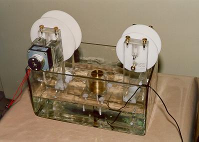
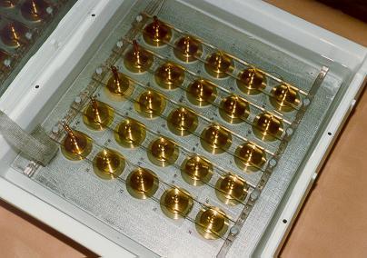
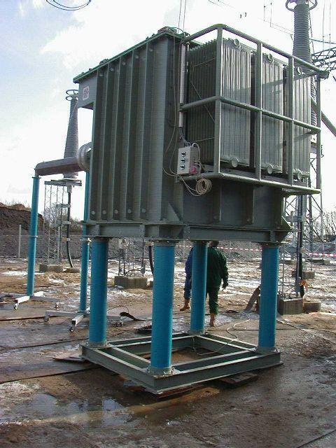
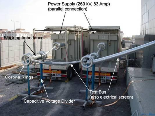
58 Routine and Sample Tests Faraday cage and Transformer for Routine Testing

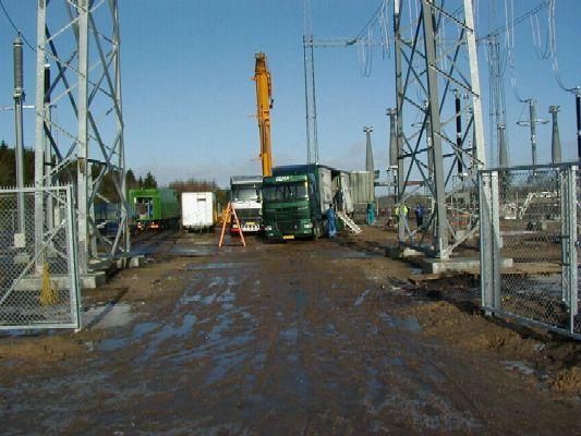
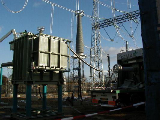
59 Equipment for Sample Testing Sample testing cable+accessories of a 400 kv cable system

60 6 How to check the quality of the installation of accessories?
61 Commissioning tests Proving the wiring that provides remote control, signalling and measurement equipment. Tests for correct operation of remote control, signalling and measurement equipment. Checking the electrical clearances and conductor sag for the jumpers When use of DTS, taking the initial Route Temperature Profile of the system Tests after installation of underground sections test of the oversheath electrical test of the main insulation
62 Electrical Tests After Installation Tests on new installations are carried out when the installation of the cable and its accessories has been completed. An oversheath test and/or an a.c. insulation test is recommended. For installations where the oversheath test is carried out, quality assurance procedures during installation of accessories may, by agreement between the purchaser and contractor, replace the insulation test.
63 Electrical Tests after Installation DC voltage test of the oversheath The voltage level and duration specified in clause 5 of IEC shall be applied between each metal sheath or concentric wires or tapes and the ground. For the test to be effective, it is necessary that the ground makes good contact with all of the outer surface of the oversheath. A conductive layer on the oversheath can assist in this respect. AC voltage test of the insulation The a.c. test voltage (20 Hz to 300 Hz) to be applied shall be subject to agreement between the purchaser and the contractor. The waveform shall be substantially sinusoidal. The voltage shall be applied for 1 h, either with a voltage according to table 10 or with 1,7 U0, depending on practical operational conditions. Alternatively, a voltage of U0 may be applied for 24 h.

64 Tests of the underground section (ref: Electra 173,1997 by WG 21-09/2 and IEC Hours at Uo Higher test voltages from 1.1 to 1.7 Uo with dedicated equipment access in the vicinity of termination distances between live parts and surrounding equipment
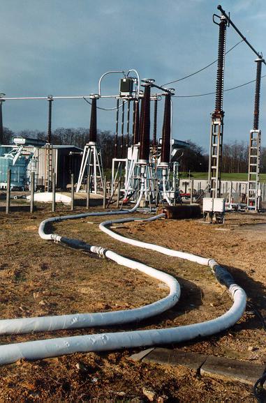
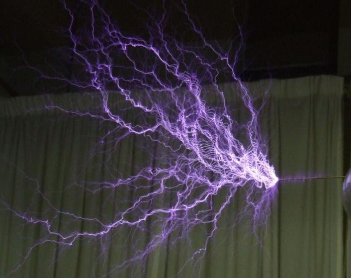
65 Electrical tests on HV/EHV cable circuits
66 Electrical Tests

67 7 Some Special Purpose Tests


68 Some Special Purpose Tests Corrosion test on laminate coverings Short Circuit Test


69 8 Extension of qualification Tests
70 Extension of qualification This item will be addressed in a further Educational Session
71 Thank You for your attention Questions?
Underground System Design TADP 547
 Underground System Design TADP 547 Industry Standards, Specifications and Guides Presentation 6.4 Instructor: Frank Frentzas Industry Organizations Several professional organizations develop standards
All the standards referred to the most current issue, including all amendment supplements. as of the date of the bid.
 1. Scope This specification defines the methods, the procedures and the requirements to verify the cables manufactured according to I.E.C. Specifications NPS361. 2. Standards All the standards referred
ECP HV INSULATION TESTING
 Document Number: ECP 11-0006 Network(s): Summary: All ENGINEERING COMMISSIONING PROCEDURE ECP 11-0006 HV INSULATION TESTING This standard details the policy for the on-site insulation testing of new and
EDS LV WAVEFORM MAINS CABLE RATINGS
 Document Number: EDS 02-0033 Network(s): Summary: ENGINEERING DESIGN STANDARD EDS 02-0033 LV WAVEFORM MAINS CABLE RATINGS EPN, LPN, SPN This standard details the technical and practical information required
EI HIGH VOLTAGE INSULATION TESTING POLICY
 Network(s): Summary: ENGINEERING INSTRUCTION EI 09-0001 HIGH VOLTAGE INSULATION TESTING POLICY EPN, LPN, SPN This engineering instruction details the policy for the on-site insulation testing of new and
TRANSMISSION ENGINEERING STANDARD TES-P , Rev. 0 TABLE OF CONTENTS 1.0 SCOPE 2.0 BONDING METHODS
 1.0 SCOPE 2.0 BONDING METHODS 2.1 Introduction 2.2 Design 2.3 Single-Point Bonding 2.4 Cross Bonding 2.5 Sheath Sectionalizing Joints 2.6 Sheath Standing Voltage 2.7 Sheath Voltage at Through Fault 2.8
EDS KV SINGLE CORE XLPE CABLES
 THIS IS AN UNCONTROLLED DOCUMENT, THE READER MUST CONFIRM ITS VALIDITY BEFORE USE Document Number: EDS 02-0034 ENGINEERING DESIGN STANDARD EDS 02-0034 33KV SINGLE CORE XLPE CABLES Network(s): EPN, LPN,
REPORT OF PERFORMANCE TIC
 REPORT OF PERFORMANCE TIC 1580-13 OBJECT TYPE Three-core power cable 18/30(36) kv, 3x500 mm2, 2XWY(P)-FR XLPE Rated voltage, U 0/U (U m) 18/30 (36) kv Conductor material Cu Conductor cross-section 3x500
Cable Protection against Earth Potential Rise due to Lightning on a Nearby Tall Object
 Cable Protection against Earth Potential Rise due to Lightning on a Nearby Tall Object U. S. Gudmundsdottir, C. F. Mieritz Abstract-- When a lightning discharge strikes a tall object, the lightning current
76 / 132 (145) kv 1x1200 mm 2 CU/XLPE/CWS/AL/HDPE
 kv 1x1200 mm 2 CU/XLPE/CWS/AL/HDPE") 09-1026 TYPE TEST CERTIFICATE OF COMPLETE TYPE TEST OBJECT single-core power cable TYPE 76 / 132 (145) kv 1x1200 mm 2 CU/XLPE/CWS/AL/HDPE Rated voltage, U o /U (U m ) 76/132 (145) kv Conductor material
09-1026 TYPE TEST CERTIFICATE OF COMPLETE TYPE TEST OBJECT single-core power cable TYPE 76 / 132 (145) kv 1x1200 mm 2 CU/XLPE/CWS/AL/HDPE Rated voltage, U o /U (U m ) 76/132 (145) kv Conductor material
Tratos High Voltage cables
 March 2013 Tratos High Voltage cables Cables for a moving world www.tratos.eu Introduction High Voltage Cables Tratos is an international manufacturer and supplier of High & Extra High Voltage cable up
Fault location on power cables. Fault location on power cables
 Fault location on power cables Fault location on power cables Contents: 1. Introduction 2. Construction of power cables 3. Cable faults 1. Introduction Fault location on communication and power cables
ECP HV INSULATION TESTING
 Document Number: ECP 11-0006 Network(s): Summary: ENGINEERING COMMISSIONING PROCEDURE EPN, LPN, SPN ECP 11-0006 HV INSULATION TESTING This standard details the policy for the on-site insulation testing
EXTREMELY LOW MAGNETIC FIELD (ELMF) XLPE INSULATED CABLES, TYPE N2XY/FR1 0.6/1 KV
 XLPE INSULATED CABLES, TYPE N2XY/FR1 0.6/1 KV") CABLE DESCRIPTION Single- or multi-phase electric cable for creating a weak external magnetic field,so as to obtain a cable wherein at last one of the conductors is assembled from two or more insulated
CABLE DESCRIPTION Single- or multi-phase electric cable for creating a weak external magnetic field,so as to obtain a cable wherein at last one of the conductors is assembled from two or more insulated
SPECIFICATION SS-140/9. 0.6/1 (1.2) kv CONTROL AND POWER UNDERGROUND CABLES WITH PVC OR XLPE INSULATION AND PVC JACKET
 kv CONTROL AND POWER UNDERGROUND CABLES WITH PVC OR XLPE INSULATION AND PVC JACKET") INDEPENDENT POWER TRANSMISSION OPERATOR S.A. TNPRD/ SUBSTATION SPECIFICATION & EQUIPMENT SECTION December 2016 SPECIFICATION 0.6/1 (1.2) kv CONTROL AND POWER UNDERGROUND CABLES WITH PVC OR XLPE INSULATION
INDEPENDENT POWER TRANSMISSION OPERATOR S.A. TNPRD/ SUBSTATION SPECIFICATION & EQUIPMENT SECTION December 2016 SPECIFICATION 0.6/1 (1.2) kv CONTROL AND POWER UNDERGROUND CABLES WITH PVC OR XLPE INSULATION
EDS KV TRIPLEX CABLE RATING
 Document Number: EDS 02-0027 Network(s): Summary: EPN, LPN, SPN ENGINEERING DESIGN STANDARD EDS 02-0027 11KV TRIPLEX CABLE RATING This engineering design standard provides the cable ratings and important
Standard Technical Specifications for Electrical Works CABLES AND ACCESSORIES. 11 kv XLPE-Insulated Three-Core Underground Cables
 Standard Technical Specifications for Electrical Works CABLES AND ACCESSORIES ( Data Sheets ) 11 kv XLPE-Insulated Three-Core Underground Cables (3x240 mm 2 ) ADWEA/ADDC/AADC STANDARD : D-AAA-CAB-11-3Cx240
A6.6 9 th International Conference on Insulated Power Cables A6.6
 Development Process of extruded HVDC cable systems Dominik HÄRING, Gero SCHRÖDER, Andreas WEINLEIN, Axel BOSSMANN Südkabel GmbH, (Germany) dominik.haering@suedkabel.com, gero.schroeder@suedkabel.com, andreas.weinlein@suedkabel.com,
NPS/002/016 Technical Specification for 33 kv Cable Joints and Terminations
 Version: 3.1 Date of Issue: September 2016 Page: 1 of 21 NPS/002/016 Technical Specification for 33 kv Cable Joints and Terminations 1. Purpose The purpose of this document is to detail the technical requirements
11-SDMS-03 REV. 02 SPECIFICATIONS FOR
 11-SDMS-03 REV. 02 SPECIFICATIONS FOR XLPE INSULATED POWER CABLES FOR RATED VOLTAGES FROM 15 KV UP TO 36 KV (U m ) This specification is property of SEC and subject to change or modification without notice
USING DAMPED AC VOLTAGES
 MODERN & TESTING DIAGNOSIS OF POWER CABLES USING DAMPED AC VOLTAGES BY EDWARD GULSKI AND ROGIER JONGEN, Onsite HV Solutions ag, Switzerland AND RALPH PATTERSON, Power Products & Solutions LLC, United States
Partial Discharge Measurement and Monitoring on High Voltage XLPE Cables
 21, rue d Artois, F-75008 PARIS AUCKLAND 2013 http : //www.cigre.org Partial Discharge Measurement and Monitoring on High Voltage XLPE Cables Michael Krüger, Rene Hummel, Stefan Böhler, OMICRON Austria
POWER TRANSFORMER SPECIFICATION, DESIGN, QUALITY CONTROL AND TESTING 18 MARCH 2009
 POWER TRANSFORMER SPECIFICATION, DESIGN, QUALITY CONTROL AND TESTING 18 MARCH 2009 Nkosinathi Buthelezi Senior Consultant: Power Transformers and Reactors Presentation Content Standardization of Power
Estimating the Impact of VLF Frequency on Effectiveness of VLF Withstand Diagnostics
 Estimating the Impact of VLF on Effectiveness of VLF Withstand Diagnostics Nigel Hampton (1), Jean Carlos Hernandez-Mejia (2), Marina Kuntsevich (3), Joshua Perkel (1), Vivek Tomer (3) 1 - NEETRAC, Atlanta,
POWER AND COMMUNICATION CABLES Theory and Applications
 POWER AND COMMUNICATION CABLES Theory and Applications Edited by R. Bartnikas, Editor Institut de Recherche dhydro-quebec Varennes, Quebec, Canada K. D. Srivastava, Coeditor University of British Columbia
Power Cables and their Application
 Power Cables and their Application Parti Materials Construction Criteria for Selection Project Planning Laying and Installation Accessories Measuring and Testing Editor: Lothar Heinhold 3rd revised edition,
SANS 1339:2010 Electric cables Cross-linked polyethylene (XLPE) insulated cables for rated voltages 3,8/6,6 kv to 19/33 kv
 insulated cables for rated voltages 3,8/6,6 kv to 19/33 kv") DRAFT SOUTH AFRICAN STANDARD (DSS): PUBLIC ENQUIRY STAGE Document number: 66/1339/4 Reference: SANS 1339 Date of circulation: 2009-12-08 Closing date: 2010-02-08 Number and title: SANS 1339:2010 Electric
DRAFT SOUTH AFRICAN STANDARD (DSS): PUBLIC ENQUIRY STAGE Document number: 66/1339/4 Reference: SANS 1339 Date of circulation: 2009-12-08 Closing date: 2010-02-08 Number and title: SANS 1339:2010 Electric
MV water-proof and water tree retardant power cable
 MV water-proof and water tree retardant power cable 1 Standard GB/T16-8 1kV 35kV, IEC The products should be manufactured according to standard GB/T16-8 and also as per IEC, BS and HD as requested. 2 Application
HO7RN-F 450/750V BS EN Highly Flexible Rubber Cable
 Rubber Insulation and Rubber Sheathed Application Range Heavy duty flexible cables for medium mechanical stress For dry and wet applications Can be used for domestic electric tools According to HD 516
High Voltage Instrumentation Cables for the ITER Superconducting Magnet Systems
 High Voltage Instrumentation Cables for the ITER Superconducting Magnet Systems Summary for Call for Nominations 1. Background and scope ITER will be the world's largest experimental facility to demonstrate
JULY Standards are finally approved by the Standards High Council of Iranian Ministry of Petroleum.
 FOREWORD This Standard is intended to be used within and for Iranian Ministry of Petroleum (N.I.O.C, N.I.G.C, N.P.C., N.I.O.R.D.C. and other affiliate organizations and companies) and has been prepared
HV SYSTEMS. Prysmian HV Systems Product Range 66kV & 132 kv
 HV SYSTEMS Prysmian HV Systems Product Range 66kV & 132 kv Prysmian HV Product Range Version: 06/10 The History of Cables 66kV Copper Conductor XLPE Insulated Cables Prysmian Cables & Systmes Ltd is part
EXCELLENT ELECTRICAL PERFORMANCES
 50OHMS CORRUGATED COPPER TUBE COAXIAL CABLE PRODUCT INTRODUCTION 2 Hansen's manufacturing of wide-scope 50ohms corrugated copper coaxial Cable is the fruitful result of the engineers' diligent research
شركة الوقت للكهرباء والمقاوالت ذ.م.م.
 CONTRACTING COMPANY W.L.L. is a leading corporate in the United Arab Emirates offering quality services in the field of High Voltage Electrical work 400, 132 & 33 kv and Medium Voltage Power Distribution
Aspects of PD interpretation in HV power cables. by Edward Gulski, Piotr Cichecki, Rogier Jongen
 Aspects of PD interpretation in HV power cables by Edward Gulski, Piotr Cichecki, Rogier Jongen General There are several aspects having influence on the diagnostic information and the condition judgment
Medium Voltage Power Cables
 N2XSY 6/0, /20, /30 NA2XSY 6/0, /20, /30 N2XS2Y 6/0, /20, /30 NA2XS2Y 6/0, /20, /30 N2XS(F)2Y 6/0, /20, /30 NA2XS(F)2Y 6/0, /20, /30 N2XSEY 3 x 6/0 Medium Voltage Power Cables Photo: HELUKABEL Q 47 Medium
Premoulded cable joint SMPGB
 Premoulded cable joint SMPGB 362-420 Premoulded for safe and easy installation Active pressure Reliable Joint bodies routinetested according to IEC before delivery Bolt connector technology Compact joint
PD Testing Considerations for MV Plant Cables
 PD Testing Considerations for MV Plant Cables Cable Testing Philosophy Damage Mistake Aging Repair Manufacturing Transportation Installation Operation Power frequency 50/60 Hz Power frequency 50/60 Hz
Testing Manual for Electrical Equipment
 EPPM, Singapore, 20-21 Sep 2011 Abstract Testing Manual for Electrical Equipment Nahed Al-Hajeri 1 and Anantha Madhavan 2 Quality Assurance (QA) refers to a program for the systematic monitoring and evaluation
High Voltage Cable Systems
 High Voltage Cable Systems Cables and Accessories up to 550 kv Completing the picture nkt cables part of a world, counting on reliable and available electrical power Today a world without electrical power
Power Frequency Withstand Voltage On-site testing of 400 kv GIS
 Power Frequency Withstand Voltage On-site testing of 400 kv GIS D. Anaraki Ardakani, A. Omidkhoda, M. Solati High Voltage Engineering Center ACECR Tehran, Iran Da_ardakani@yahoo.com Paper Reference Number:
General Technical Specification and Execution Procedures for Transmission and Subtransmission Networks Cables
 Islamic Republic of Iran Vice Presidency for Strategic Planning and Supervision General Technical Specification and Execution Procedures for Transmission and Subtransmission Networks Cables NO: 452-1 Office
Testing of 400 kv GIS
 Testing of 400 kv GIS Robert le Roux, Dermot Dorgan, Brian Perry ESB International - Ireland Paper 028 1 Introduction The 400 kv transmission is designed for critical periods of low loading. Due to critical
AORC Technical meeting 2014
 AORC Technical meeting 2014 http : //www.cigre.org B1-1110 Development of ±160 kv XLPE Cable and its Application to the World s First Three-terminal VSC HVDC System in China Lin-jie Zhao, Hong Rao, Xiao-lin
EDS LV SUPPLIES TO MOBILE PHONE BASE STATIONS MOUNTED ON TRANSMISSION TOWERS
 ENGINEERING DESIGN STANDARD EDS 08-2109 LV SUPPLIES TO MOBILE PHONE BASE STATIONS MOUNTED ON TRANSMISSION TOWERS Network(s): Summary: EPN, LPN, SPN This standard provides guidance on the installation of
conductor Extruded Cross - Linked Polyethylene Insulated (XLPE) Power Cable Rated Voltage U 0 /U = 12/20 kv U 0 /U = 18/30 kv
 Power Cable Rated Voltage U 0 /U = 12/20 kv U 0 /U = 18/30 kv") Israel Electric Corporation Ltd. - Customer Division - National Network Unit Issued date: February 2018 THE ISRAEL ELECTRIC CORPORATION LTD. National Network Unit Specification No. NPS - 361 for Single
Israel Electric Corporation Ltd. - Customer Division - National Network Unit Issued date: February 2018 THE ISRAEL ELECTRIC CORPORATION LTD. National Network Unit Specification No. NPS - 361 for Single
CIGRE- AORC Technical Meeting 2016 and International Conference on Global Trends in the Development of Power T&D System including Smart Grid
 CIGRE- AORC Technical Meeting 2016 and International Conference on Global Trends in the Development of Power T&D System including Smart Grid DEMANDS OF DIELECTRIC TESTING OF HVAC AND HVDC POWER CABLES
Transformer Technology Seminar What to consider at Design Reviews
 Pomona CA, May 24-25, 2016 Transformer Technology Seminar Siemens AG Transformers siemens.com/answers Why to perform Design Review Meetings? To ensure both parties having the same understanding of the
Reprint E Two Years of Experience with a Mobile Resonant Test System for Testing of Installed Medium- and High Voltage Power Cables
 Two Years of Experience with a Mobile Resonant System for ing of Installed Medium- and High Voltage Power Cables P. Schikarski M. Gamlin J. Rickmann P. Peeters P. v.d. Nieuwendijk R. Koning Reprint ISH
147,LoharChawl,9,TavawalaBuilding,1stFloor,MUMBAI
 DEALERSIN:WIRESCABLES&ELECTRICALS 147,LoharChawl,9,TavawalaBuilding,1stFloor,MUMBAI-400002. Tel.:22064216,39567822,22096361.E-mail:dvcable@gmail.com,Web.:www.dvcable.in INTRODUCTION As India marches towards
CIGRE General Session, Paris 2014 Group Meeting SC B1 Insulated Cables, 27th August, 2014 Results of CAG Questionnaire
 1 1. Number of Questionnaires Returned 23 2. Number of suggestions for work 64 3. Suggestions for new work within the scope of SCB1 or for additional work by current Working Groups in? 3.1 cable system
MV Power Cable Testing Training
 MV Power Cable Testing Training Contact us Today for a FREE quotation to deliver this course at your company?s location. https://www.electricityforum.com/onsite-training-rfq Since power cables are used
WIRE AND CABLE ENGINEERING GUIDE
 Excerpt From Prysmian s WIRE AND CABLE ENGINEERING GUIDE Page 1 of 8 CABLE TESTING Testing represents an integral part in the life of a cable. A cable will be subjected to multiple tests in its lifetime
Diagnostic testing of cast resin transformers
 Paper of the Month Diagnostic testing of cast resin transformers Author Michael Krüger, OMICRON, Austria michael.krueger@omiconenergy.com Christoph Engelen, OMICRON, Austria christoph.engelen@omicronenergy.com
HIGH PRESSURE MOULDING TECHNOLOGY
 HIGH PRESSURE MOULDING TECHNOLOGY Romuald Lemaitre, Pierre Gaillard, Franck Tortey, Paul Woodward franck.tortey@alcatel-lucent.fr Alcatel - Lucent, 536 Quai de La Loire 62100 Calais Abstract: The Optical
Testing 320 kv HVDC XLPE Cable System
 Testing 320 kv HVDC XLPE Cable System H. He, W. Sloot DNV GL, KEMA Laboratories Arnhem, The Netherlands Abstract Two unique test requirements in testing of a high- voltage direct- current (HVDC) cable
Testing and PD Diagnosis of MV Cable Systems with DAC Voltage Educational Session May St Pete Beach, Fl
 Testing and PD Diagnosis of MV Cable Systems with DAC Voltage Educational Session May 26 2011 St Pete Beach, Fl HDW ELECTRONICS, INC. THE BEST IN CABLE FAULT LOCATING TECHNOLOGY by Henning Oetjen Frank
HV AC TESTING OF SUPER-LONG CABLES
 HV AC TESTING OF SUPER-LONG CABLES Stefan SCHIERIG, (Germany), schierig@highvolt.de Peter COORS, (Germany), coors@highvolt.de Wolfgang HAUSCHILD, IEC, CIGRE, (Germany), hauschild@highvolt.de ABSTRACT The
Cable diagnostic in MV underground cable networks
 Cable diagnostic in MV underground cable networks Theoretical background and practical application VLF testing tan delta loss factor measurement Partial discharge localization and measurement Author: Tobias
Power Voltage Transformers for Air Insulated Substations. THE PROVEN POWER.
 Power Voltage Transformers for Air Insulated Substations THE PROVEN POWER. Introduction Trench Power Voltage Transformers (Power VTs) combine the attributes of an inductive voltage transformer with the
This Certificate consists of 75 pages in total.
 Object Heat shrinkable indoor termination 1086-16 Type MZDNK-3-15-C Rated voltage, U 0 /U (U m ) 8,7/15 (17,5) kv Conductor material Cu Conductor cross-section 3 x 185 mm 2 Insulation material XLPE Manufacturer
CHAPTER 2. v-t CHARACTERISTICS FOR STANDARD IMPULSE VOLTAGES
 23 CHAPTER 2 v-t CHARACTERISTICS FOR STANDARD IMPULSE VOLTAGES 2.1 INTRODUCTION For reliable design of power system, proper insulation coordination among the power system equipment is necessary. Insulation
THIS IS AN UNCONTROLLED DOCUMENT, THE READER MUST CONFIRM ITS VALIDITY BEFORE USE. Contents
 Document Number: EOS 09-0100a Contents 1 Introduction... 2 2 Cable Routes/Joints... 2 3 Cable Details... 2 4 Cable Warning Markers... 4 5 Cable Drum Numbers... 4 6 Ducts - Including those used in a Directional
Substation HV Cables. Document Number: 1-11-FR-07
 Substation HV Cables Document Number: 1-11-FR-07 VERSION 1.0 June 2018 This functional requirements document is in line with the organisation's 1-11-ACS-07 Substation HV Cables Asset Class Strategy Intellectual
SPECIFICATION No SS-135/ kv METAL OXIDE SURGE ARRESTERS WITHOUT GAPS
 -1- INDEPENDENT POWER TRANSMISSION OPERATOR S.A. TNPRD/ SUBSTATION SPECIFICATION & EQUIPMENT SECTION June 2013 SPECIFICATION No 150 kv METAL OXIDE SURGE ARRESTERS WITHOUT GAPS I. SCOPE This specification
Assuring the Reliability of Critical Power Cable Systems
 Assuring the Reliability of Critical Power Cable Systems Presented by: Benjamin Lanz Manager of Application Engineering IMCORP Power Cable Reliability Consulting & Diagnostics Some of the technologies
Specialists in HV and MV test and diagnostics. Testing in Substations
 Specialists in HV and MV test and diagnostics Testing in Substations Testing in Substations Testing in Substations At 4fores we specialize in the diagnosis and measurement of all types of existing technologies
Hendrix Tap, Tie & Ground Wire
 Hendrix Tap, Tie & Ground Wire MADE IN U.S.A. 53 Old Wilton Road Milford, NH 03055-3119 603-673-2040 www.marmonutility.com A Marmon Wire & Cable/Berkshire Hathaway Company Tap Wire Description Hendrix
S-Link. RF Cable Solution
 S-Link RF Cable Solution Netop supplys complete RF subsystem for site application with Rosenberger S-Link site solution package which include feeder cables, jumpers, connectors, surge arresters, grounding
MGVCL/MM/ /2082/11KV AB CABLE TECHNICAL SPECIFICATION FOR 11KV AERIAL BUNCHED CABLES FOR OVERHEAD LINES
 TECHNICAL SPECIFICATION FOR 11KV AERIAL BUNCHED CABLES FOR OVERHEAD LINES 1. Qualifying Requirement of AB Cable Manufacture/Supplier The manufacturer should have manufactured, successfully type tested
Kerman & Kavian Cable Industries ( KCI )
") KCI Kerman & Kavian Cable Industries ( KCI ) KCI Cables for control and instrumentation circuits 150/250 V (300 V) According to of IEC 60092-376 (2003) Electrical installations in ships - Part 376: Kerman
KCI Kerman & Kavian Cable Industries ( KCI ) KCI Cables for control and instrumentation circuits 150/250 V (300 V) According to of IEC 60092-376 (2003) Electrical installations in ships - Part 376: Kerman
Statistical Characteristics of Partial Discharge Caused by Typical Defects in Cable Joint under Oscillating Voltage
 Journal of Energy and Power Engineering 9 () 3-3 doi:.7/93-897/.3. D DAVID PUBLISHIG Statistical Characteristics of Partial Discharge Caused by Typical Defects in Cable Joint under Oscillating Voltage
High Votage Module AC/DC/Impulse Test System
 TSGADI Series High Votage Module AC/DC/Impulse Test System A digital control and measuring system is used to be control the difference output AC/DC/Impulse and related protection device such as over voltage
ASTA TEST REPORT NO: HEATSHRINK TERMINATIONS 3 CORE 12kV PILC AND XLPE
 ASTA TEST REPORT NO: 2212 HEATSHRINK TERMINATIONS 3 CORE 12kV PILC AND XLPE UNIVERSAL 12kV HEATSHRINK JOINT TO SUIT 3 CORE XLPE / PILC CABLES INLINE OR TRANSITION RECORD OF PROVING TESTS Page 1 of 6 Laboratory
Notes 3 Explanatory Information 4-10
 Low Voltage Cables Section Three SECTION THREE - LOW VOLTAGE CABLES PAGE Notes 3 Explanatory Information 4-10 Construction 4 Current Ratings 5 Rating Factors 6 Voltage Drops 8 Selection Procedures 10 Minimum
AMENDMENT NO. 1 SEPTEMBER IS (Part 1) : 2001/IEC (1991) SURGE ARRESTORS
 : 2001/IEC (1991) SURGE ARRESTORS") AMENDMENT NO. 1 SEPTEMBER 2011 TO IS 15086 (Part 1) : 2001/IEC 60099-1 (1991) SURGE ARRESTORS PART 1 NON-LINEAR RESISTOR TYPE GAPPED SURGE ARRESTORS FOR a.c. SYSTEMS (The Amendment was originally published
AMENDMENT NO. 1 SEPTEMBER 2011 TO IS 15086 (Part 1) : 2001/IEC 60099-1 (1991) SURGE ARRESTORS PART 1 NON-LINEAR RESISTOR TYPE GAPPED SURGE ARRESTORS FOR a.c. SYSTEMS (The Amendment was originally published
INTRODUCTION NUHAS OMAN QUALITY & RELIABILITY.
 INTRODUCTION Nuhas Oman LLC, an integral part of The Al Bahja Group of Companies, is a Quality producer of: HV, MV and LV Cables Enamelled Copper Wires Oxygen Free Continuous Cast Copper Wire Rods Drawn
DESIGN OF A 45 CIRCUIT DUCT BANK
 DESIGN OF A 45 CIRCUIT DUCT BANK Mark COATES, ERA Technology Ltd, (UK), mark.coates@era.co.uk Liam G O SULLIVAN, EDF Energy Networks, (UK), liam.o sullivan@edfenergy.com ABSTRACT Bankside power station
MATEFU Insulation co-ordination and high voltage testing of fusion magnets
 Stefan Fink: MATEFU Insulation co-ordination and high voltage testing of fusion magnets Le Chateau CEA Cadarache, France April 7th, 29 Insulation co-ordination Some principle considerations of HV testing
A Review Comprehension: Guideline for Testing of HV, EHV and UHV Substation Equipment
 International Research Journal of Engineering and Technology (IRJET) eissn: 23 0056 Volume: 04 Issue: 02 Feb 2017 www.irjet.net pissn: 072 A Review Comprehension: Guideline for Testing of HV, EHV and UHV
Comparison of CAN/CSA C88.1, IEEE C /01 & IEC 60137
 ITEM Power factor (tanδ) & Capacitance Measurement Dry 1-minute Power frequency with partial discharge measurement CAN/CSA C88.1-96 IEEE C57.19.00/01 IEC 60137 Requirement Requirement Requirement Clause
CHAPTER 10 HIGH VOLTAGE TESTING OF ELECTRICAL APPARATUS
 CHAPTER 10 HIGH VOLTAGE TESTING OF ELECTRICAL APPARATUS 1. Introduction 2. Classification of High Voltage Tests 3. Test Voltages 4. High Voltage Testing of Electrical Apparatus 1. INTRODUCTION Purpose
SECTION MEDIUM-VOLTAGE CABLES
 PART 1 - GENERAL 1.1 DESCRIPTION SECTION 26 05 13 MEDIUM-VOLTAGE CABLES SPEC WRITER NOTE: Delete between //-----// if not applicable to project. Also delete any other item or paragraph not applicable in
Evaluating Step and Touch Potential Risks on Earthing Systems of High Voltage Cable Systems TP, THINUS DU PLESSIS ESKOM SOUTH AFRICA HJ, HARTMUT JAGAU
 Technology solutions and innovations for developing economies Evaluating Step and Touch Potential Risks on Earthing Systems of High Voltage Cable Systems TP, THINUS DU PLESSIS ESKOM SOUTH AFRICA HJ, HARTMUT
INSULATION DIAGNOSIS OF HIGH VOLTAGE POWER CABLES
 INSULATION DIAGNOSIS OF HIGH VOLTAGE POWER CABLES Edward GULSKI, Delft University of Technology, (The Netherlands), e.gulski@tudelft.nl Johan J SMIT, Delft University of Technology, (The Netherlands),
TECHNICAL SPECIFICATION FOR 11KV, 3C x95mm mm 2 AERIAL BUNCHED CABLES FOR OVERHEAD LINES (CROSSED LINKED POLYTHENE DRY GAS CURED)
") TECHNICAL SPECIFICATION FOR 11KV, 3C x95mm 2 + 80mm 2 AERIAL BUNCHED CABLES FOR OVERHEAD LINES (CROSSED LINKED POLYTHENE DRY GAS CURED) 1. SCOPE This specification covers requirements of, 3C x95mm 2 +
TECHNICAL SPECIFICATION FOR 11KV, 3C x95mm 2 + 80mm 2 AERIAL BUNCHED CABLES FOR OVERHEAD LINES (CROSSED LINKED POLYTHENE DRY GAS CURED) 1. SCOPE This specification covers requirements of, 3C x95mm 2 +
Pulse Cable for TESLA Modulators Hans-Jörg Eckoldt DESY TESLA
 Pulse Cable for TESLA Modulators Hans-Jörg Eckoldt DESY TESLA 2000-35 1 Introduction... 3 2 Demands for the cable... 3 3 Cable construction... 3 4 Simulation results... 4 5 Installation... 7 6 Cooling...
Prepared by Mick Maytum
 IEC Technical Committee 109: Standards on insulation co-ordination for low-voltage equipment Warning Prepared by Mick Maytum mjmaytum@gmail.com The document content is of a general nature only and is not
36kV VOLTAGE TRANSFORMERS (OUTDOOR TYPE)
") CEB STANDARD 022 : 1994 Specification for 36kV VOLTAGE TRANSFORMERS (OUTDOOR TYPE) CEYLON ELECTRICITY BOARD SRI LANKA Specification for 36kV VOLTAGE TRANSFORMERS (OUTDOOR TYPE) CEB Standard 022 : 1994
CEB STANDARD 022 : 1994 Specification for 36kV VOLTAGE TRANSFORMERS (OUTDOOR TYPE) CEYLON ELECTRICITY BOARD SRI LANKA Specification for 36kV VOLTAGE TRANSFORMERS (OUTDOOR TYPE) CEB Standard 022 : 1994
Generation of Sub-nanosecond Pulses
 Chapter - 6 Generation of Sub-nanosecond Pulses 6.1 Introduction principle of peaking circuit In certain applications like high power microwaves (HPM), pulsed laser drivers, etc., very fast rise times
MV Power Cable Diagnostics by Frequency Domain Spectroscopy. Peter Werelius Programma Electric AB
 MV Power Cable Diagnostics by Frequency Domain Spectroscopy Peter Werelius Programma Electric AB Frequency Domain Spectroscopy Measurements of insulation capacitance and losses in a frequency interval
INSTRUMENT TRANSFORMERS. Product Spectrum
 INSTRUMENT TRANSFORMERS Product Spectrum Context The transmission of energy from the generation sites to the places of use is carried out through high voltage electrical lines and substations as interconnecting
Chapter Seven. Under Ground Cables
 Chapter Seven Under Ground Cables Construction of cables In the fig (7.1)below, shows the general construction of (3-condctor) cable The various part of cable are : 1- Core or conductor A cable may have
This is a preview - click here to buy the full publication. IEC 2006 Copyright - all rights reserved
 INTERNATIONAL STANDARD IEC 60287-1-1 Second edition 2006-12 Electric cables Calculation of the current rating Part 1-1: Current rating equations (100 % load factor) and calculation of losses General IEC
THE PROPAGATION OF PARTIAL DISCHARGE PULSES IN A HIGH VOLTAGE CABLE
 THE PROPAGATION OF PARTIAL DISCHARGE PULSES IN A HIGH VOLTAGE CABLE Z.Liu, B.T.Phung, T.R.Blackburn and R.E.James School of Electrical Engineering and Telecommuniications University of New South Wales
HOW TO SAFE GUARD THE TRANSFORMER..???
 CPRI HOW TO SAFE GUARD THE TRANSFORMER..??? CPRI Efficient and Effective network planning, Design and Forecasting Highly Reliable and Stable Protection system and co-ordination Measures to mitigate various
Y-CY-JZ flexible, CU-screened, transparent, EMC-preferred type, meter marking
 Y-CY-JZ flexible, CU-screened, transparent, EMC-preferred type, meter marking A Technical data Special PVC control cables, adapted to DINVDE0 part3 Temperature range flexing -5 C ) to +0 C fixed installation
MEDIUM VOLTAGE TERMINATIONS CATALOGUE 2017
 MEDIUM VOLTAGE TERMINATIONS CATALOGUE 01 NEXANS NETWORK SOLUTIONS DIV. EUROMOLD COMPANY PRESENTATION EUROMOLD Euromold is the leading European specialised designer, manufacturer and distributor of prefabricated
MGM Transformer. Vacuum Pressure Impregnated (VPI) Dry-Type Substation Transformer Specification Guide
 Dry-Type Substation Transformer Specification Guide") MGM Transformer Vacuum Pressure Impregnated (VPI) Dry-Type Substation Transformer Specification Guide MGM Transformer Company 5701 Smithway Street Commerce, CA 90040 www.mgmtransformer.com Phone: 323.726.0888
MGM Transformer Vacuum Pressure Impregnated (VPI) Dry-Type Substation Transformer Specification Guide MGM Transformer Company 5701 Smithway Street Commerce, CA 90040 www.mgmtransformer.com Phone: 323.726.0888
VSD cables in. Working with. industrial & automation applications
 Cable Efficiency in Automation Connectivity Cabinet Control Working with VSD cables in industrial & automation applications Description of a VSD System A functional VSD system consists of at least three