A Bavarian Initiative towards a Robust Galileo PRS Receiver
|
|
|
- Ashley Waters
- 6 years ago
- Views:
Transcription
1 A Bavarian Initiative towards a Robust Galileo PRS Receiver Alexander Ruegamer, Ion Suberviola, Frank Foerster, Guenter Rohmer, Fraunhofer IIS Andriy Konovaltsev, Nikola Basta, Michael Meurer, German Aerospace Center (DLR) Jan Wendel, Melanie Kaindl, EADS Astrium Stefan Baumann, IABG BIOGRAPHY Alexander Ruegamer received his Dipl.-Ing. (FH) degree in Electrical Engineering from the University of Applied Sciences Wuerzburg-Schweinfurt, Germany, in Since the same year he works at the Fraunhofer Institute for Integrated Circuits IIS in the field of GNSS front-end receiver development with focus on multi-band reception, integrated circuits and immunity to interference. Ion Suberviola received his Master Telecommunications Engineer degree in 2006 from the University of Navarra (TECNUN), in San Sebastian, Spain. He did his diploma thesis at Fraunhofer Institute for Integrated Circuits, in Nuremberg, Germany, about GNSS acquisition methods and stayed there working as algorithm and HW designer. Frank Foerster has received his M.S. degree in electrical engineering from the University of Erlangen-Nuremberg, Germany, in Since then, he is at the Fraunhofer Institute for integrated circuits in Erlangen as a system design engineer. Currently he is involved in several navigation and communication projects where he is developing the analog RF part. Guenter Rohmer received his Dipl.-Ing. degree in Electrical Engineering in 1988 and the PhD in 1995 from the University of Erlangen, Germany. Since 2001 he is head of a department at the Fraunhofer Institute for Integrated Circuits dealing with the development of components for satellite navigation receivers, indoor navigation and microwave localization systems. Andriy Konovaltsev received his engineer diploma and the Ph.D. degree in electrical engineering from Kharkov State Technical University of Radio Electronics, Ukraine in 1993 and 1996, correspondingly. He joined the Institute of Communications and Navigation of DLR in His research interests are in array processing for satellite navigation systems, signal processing algorithms for navigation receivers including synchronization, multipath and radio interference mitigation. Nikola Basta received his Dipl.-Ing. degree in 2008 at Faculty of Electrical Engineering at the University of Belgrade, Serbia. Since June 2008 he has been working in German Aerospace Centre (DLR) in the antenna group of the navigation department where he has been involved in design and characterization of antenna arrays for GNSS applications. Michael Meurer received the diploma in electrical engineering and the Ph.D. degree from the University of Kaiserslautern, Germany. After graduation, he joined the Research Group for Radio Communications at the Technical University of Kaiserslautern, Germany, as a senior key researcher, where he was involved in various international and national projects in the field of communications and navigation. Since 2005 he has been an Associate Professor (PD) at the same university. Additionally, since 2006 Dr. Meurer is with the German Aerospace Centre (DLR), Institute for Communications and Navigation, where he is the director of the Department of Navigation and of the Centre of Excellence for Satellite Navigation. Jan Wendel received the Dipl.-Ing. and Dr.-Ing. degrees in Electrical Engineering from the University of Karlsruhe in 1998 and 2003, respectively. From 2003 until 2006 he was an assistant professor at the University of Karlsruhe, where his research interests focused on integrated navigation systems and MAV flight control. Since 2006, he is private lecturer at the University of Karlsruhe. In 2006, Jan Wendel joined MBDA in Munich. Since 2009, he is with EADS Astrium GmbH in Munich, where he is involved in various activities related to satellite navigation including tracking algorithms, compatibility analysis, and interference detection and characterization. Melanie Kaindl graduated in 1998 in electrical engineering at the Aachen University of Technology. In 2005 she received her Ph.D. in communications engineering from the Munich University of Technology.
2 Since 2005 she works at EADS Astrium specialized on satellite navigation signal performance analysis and receiver algorithms. Stefan Baumann received his diploma in Physical Geography in 1995 from the Ludwig-Maximilians- University Munich and his PhD in 2002 from the Heinrich-Heine-University Duesseldorf. He is involved in GNSS- and Galileo-activities since 1996 and joined IABG in 2006 as Project Manager for security-related radio- and satellite projects. ABSTRACT This paper presents the architecture, core technologies, system development, and setup of the BaSE Galileo PRS receiver. The receiver is capable of processing Galileo E1/E6 PRS signals with broad bandwidth. In particular, its hard- and software receiver components are presented and a robust tracking method of the BOCc-modulated PRS signals is discussed. Finally, it is shown how an effective suppression of jamming and interference is achieved by combining different approaches like application of an adaptive, two frequency antenna array with a post-correlation beamforming, and a robust PVT solution with multi-frequency RAIM. DISCLAIMER All information presented and discussed within this paper is part of the public domain. The PRS information used in the paper is freely available e.g. through the GIOVE-A+B Public SIS ICD [1]. No classified documents or information were used. Consequently, the presented receiver will differ in various aspects to real Galileo PRS receivers. INTRODUCTION The increasing use of GNSS for military and security related applications is generating a higher demand for robust positioning/navigation solutions. Consequently one of the first Galileo services to become available will be the Public Regulated Service (PRS). Galileo PRS is a special navigation service intended for governmental and governmental authorized users, e.g. police, border control, emergency, armed forces and Search and Rescue (SAR), as well as operators of critical infrastructures like telecommunication- and energy-networks and critical transports. The first PRS signals will be available after the launch of the first Galileo IOV satellites in Autumn The Public Regulated Service features encrypted signals on two frequency bands with restricted access for specific authorized users as mentioned above. A PRS receiver has to deliver robust, reliable and continuous position information even under challenging reception conditions and also in jammed environments, requiring a considerable robustness against interference. Furthermore, a protection against signal meaconing and spoofing has to be provided, as well as means to control the use of GNSS signals within a local/regional area of operation. All these issues make a PRS receiver development a very demanding task. Within the BaSE (Bavarian security receiver) project, a consortium consisting of six Bavarian (Germany) companies and research institutes was formed to investigate core technologies, acquire necessary knowhow, and develop a high-end Galileo PRS receiver prototype. The consortium consists of Fraunhofer Institute for Integrated Circuits (IIS), Institute of Communications and Navigation of German Aerospace Center (DLR), IABG, EADS Astrium, NavCert, and Siemens. The project is co-financed and supported by the Bavarian Ministry of Economic Affairs. BaSE has started in February 2010 and will finish with a demonstration of the PRS prototype receiver in January Such an efficient cooperation is essential especially for the development of PRS receivers, which is associated with time-consuming processes related not only to security accreditation and certification but also to the subsequent integration of navigation equipment in dedicated platforms with specific environmental and security requirements. Further the use of PRS is (in contrast to GPS PPS) not only limited to military users, but also allowed for other governmental or governmental authorized users. Most of these new user communities do not have the same level of experience with securityrelated equipment as military users; therefore, a dedicated security-architecture has to be chosen to allow a userfriendly handling of PRS-receivers. The technological objective of BaSE is to develop a flexible and scalable high-performance Galileo PRS prototype receiver. This receiver will operate in the E1 and E6 frequency bands, making use of the Galileo PRS signal components. Special attention is given to robust acquisition and tracking of the BOCc-modulated PRS signals. Effective suppression of jamming and interference is achieved by combining different approaches like application of an adaptive, two frequency antenna array with a post-correlation beamforming. Further objectives are a robust PVT solution (Position- Velocity-Time) with multi-frequency RAIM (Receiver Autonomous Integrity Monitoring) and spoofing detection by estimating direction of arrival. Other non-technical goals of BaSE are the identification of national users and applications for Galileo PRS, the analysis of their specific requirements, the coordination with national and European PRS interfaces, projects, and developments as well as the elaboration and integration of a capable IT-security concept into the receiver system,
3 Figure 1: Galileo PRS, CS and OS signals in the E1 and E6 band and aspects related to future standardization and certification of PRS receivers. Future integration of PRS receivers into the whole Galileo PRS-Management and Security infrastructure are further tasks performed within the BaSE project. GALILEO PRS SIGNALS As depicted in Figure 1, the Galileo PRS signals are transmitted over the E1A and E6A frequency bands, using BOCc(15,2.5) and BOCc(10,5) modulation, respectively. BOCc uses a cosine phased subcarrier resulting in higher frequency components than a sine phased subcarrier used in BOCs modulations of e.g. Galileo E1BC Open Service. As a result, more energy is shifted to the edges of the band what improves the spectral separation with the coexisting OS and CS signals and the theoretical tracking performance. Since the BOCc main-lobes are at the edges of the band, the full transmitted bandwidth should be received [1]. GNSS Signal Carrier Freq. [MHz] Modulation Bandwidth [MHz] GPS L1 C/A BPSK(1) 2 Galileo E1BC OS CBOC(6,1,1/11) 14 Galileo E1A PRS BOCcos(15,2.5) 40 Galileo E6A PRS BOCcos(10,5) 40 Table 1: GNSS signals tracked by the BaSE receiver The BaSE receiver is designed to receive and process all signals listed in Table 1. The Galileo Open Service (OS) signals E1BC are exploited for the acquisition and for the tracking support of Galileo (pseudo-)prs signals. GPS L1 C/A support is included for on-field demonstrations and for general comparisons with other receivers. The E6BC signals for the planned Galileo Commercial Service (CS) are not used. The BaSE receiver uses memory codes for the local replica generation. Thus, both GIOVE-B PRS codes [1] can be used, as well as any random sequence provided by an arbitrary waveform signal generator. BASE RECEIVER HARDWARE Receiver Hardware Architecture Overview Figure 2 shows the BaSE receiver block diagram. A selfcalibrated, 4-element dual-frequency (E1 and E6) array antenna is used to set the basis for protection against signal meaconing and spoofing with high interference mitigation capabilities. The analog signal conditioning (filtering, amplification, down-conversion) is done in separate quadruple radio frequency (RF) analog frontends for E1 and E6, respectively. The analog-to-digital conversion (ADC) with digital signal conditioning is carried out in the successive digital front-ends. One digital front-end is used for the four E1 channels and one for the four E6 channels. All necessary clock signals (for the ADCs and the FPGAs) and local oscillator (LO) signals (for the analog mixer stages) are coherently derived and distributed on a dedicated clock and local oscillator generation module. Using an optical multigigabit transceiver link (MGT), the digital raw data from the digital front-ends are transferred to the pre-correlation interference mitigation module whose output is finally fed


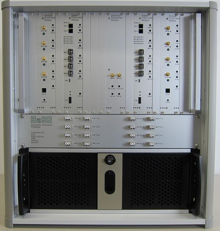
4 Figure 2: BaSE receiver block diagram into the baseband receiver hardware, again using an optical MGT. All computationally demanding tasks like, the acquisition and the correlators are implemented on the digital baseband FPGA. The tracking loops are closed in software running on a standard PC over a PCIe link where both the beamforming and the PVT with RAIM and spoofing detection are also implemented. The hardware setup of the BaSE receiver is depicted in Figure 3, excluding the antenna. The RF front-end subsystem is realized using 6 units of height modules. The interference mitigation module as well as the baseband FPGA are installed within a standard 19 rack PC. An optical cable patch panel gives the possibility to include or exclude the interference mitigation module for different signal combinations. All these components are mounted in a 19 desk chassis using overall 12 units of height. Figure 3: BaSE receiver setup without antenna
5 Array Antenna In order to have both a 4-element dual-frequency antenna and a compact design, the antenna system is based on stacked patch dual-band radiators in a 2-by-2 configuration. The feeding of the dual-output antenna element is designed for high isolation between E1 and E6 signal paths [2]. Simulated realized gain of the antenna element for the desired right hand circular polarization (RHCP) is about 5 dbi for both bands and the suppression of the cross-polarized left hand circular polarization (LHCP) component is at least 15 db. Individual wideangle patterns (Figure 4 and 5) and a /2 inter-element distance allows an efficient implementation of the antenna module. Furthermore, to improve the overall axial ratio performance, sequential rotation of elements is foreseen (Figure 6). The multilayer strip-line approach is intended for embedded calibration networks for each operational band. Therefore, online calibration is possible without dismounting the antenna. Moreover the RF board with amplification and filtering stages is attached underneath the radiators, yielding an integrated solution. Figure 6: 2x2 Antenna array with sequential rotation GNSS Front-end Sub-System The RF front-end sub-system consists of the analog RF front-end boards, a clock/local oscillator generation and distribution unit, and the digital front-end boards. Analog Front-end The RF front-ends have to be wideband to process the E1A BOCcos(15,2.5) and E6A BOCcos(10,5) modulated PRS signals and also have to be designed in a very robust way to withstand both out-of-band and in-band interferences. Figure 4: Single antenna element E6 pattern For both E1 and E6 analog front-ends, a zero-intermediate frequency (IF) architecture was chosen. A zero-if architecture is very well suited for the BOC modulated Galileo signals, since there is practically no power in the region of the carrier frequency and thus a simple ACcoupling can be used e.g. to remove the typical zero-if problem of DC-offset due to self-mixing. Thanks to zero- IF there is no need for image rejection, and high quality factor low-pass filters can be used for the band selection providing an excellent out-of-band attenuation. Figure 7 shows the general architecture of the E1/E6 front-end. RF signal limiters are foreseen after each amplification stage to protect the circuitry from powerful inband jammer with power levels greater than +20 dbm. Either ceramic or surface acoustic wave (SAW) RF filter can be used to enable flexibility in terms of broad bandwidth or high selectivity. Figure 5: Single antenna element E1 pattern


6 Figure 7: BaSE analog RF front-end architecture Figure 8 shows the signal down-conversion scheme used. The output of the analog front-end is a complex baseband signal represented with analog inphase and quadrature component signals. Figure 8: Down-conversion scheme for E1 and E6 A variable gain amplifier (VGA) is used to control the subsequent analog to digital converter (ADC) appropriately. The VGA is controlled via a serial bus by the digital front-end. Four E1 or E6 analog front-end chains are realized on a single so called E1 or E6 analog RF front-end module, depicted in Figure 9. Figure 9: Quadruple analog front-end E1/E6 module To reduce both the effort of the clock / local oscillator generation and possible interferences coming from different frequency synthesizers, as well as to ensure phase coherence, all frequency synthesizers are derived from a separate clock / LO generation and distribution module and derived from the same reference clock. This approach also allows using an external reference clock if desired.
![GNSS Signal Carrier Freq. [MHz] LO [MHz] IF [MHz] Galileo E1A 1575.42 1575 +0.42 Lower Lobe 1560.075 1575-14.925 Higher Lobe 1590.765 1575 +15.765 Galileo E6A 1278.75 1280-1.25 Lower Lobe 1268.](/docs-images/76/73105018/images/7-1.jpg "52 1280-11.48 Higher Lobe 1288.98 1280 +8.98 Table 2: Resulting IF frequencies Table 2 shows the emerging intermediate frequencies when using the proposed local oscillator frequencies.")

 interface for the transmission of the raw IF samples. Its block diagram is shown in Figure 10.")
7 GNSS Signal Carrier Freq. [MHz] LO [MHz] IF [MHz] Galileo E1A Lower Lobe Higher Lobe Galileo E6A Lower Lobe Higher Lobe Table 2: Resulting IF frequencies Table 2 shows the emerging intermediate frequencies when using the proposed local oscillator frequencies. It is generally beneficial to synthesize an LO frequency whose ratio to the reference frequency approaches as closely as possible a rational number (in our case a 10 MHz OCXO) to reduce the phase noise as much as possible. Digital Front-end The digital front-end performs the analog to digital conversion, followed by a first signal conditioning, the interference mitigation modules, and the high speed multi gigabit transceiver (MGT) interface for the transmission of the raw IF samples. Its block diagram is shown in Figure 10. the raw data is directly sent to a dedicated pre-correlation interference mitigation board (FDAF-Module). If the interference mitigation step is successful, the dynamic range can be safely reduced from the initial 14 bit to e.g. 4 bit without any significant implementation loss, since 4 bit are enough for a GNSS noise-like signal with no remaining interferences. A digital gain control with a jammer-to-noise meter capability finalizes the tasks on the digital front-end FPGA. Using a similar approach as for the analog front-ends, four E1 or E6 digital front-end chains, consisting of a dual-adc module, a digital signal processing unit and a MGT for the required 2.24 Gbit/s raw data rate (80 Msamples/s x 14 bits/sample x 2 I/Q components) per reception chain are realized on one so-called E1 or E6 digital front-end module, depicted in Figure 11. Figure 10: Digital front-end block diagram High resolution dual-adcs with 14 bit resolution and 80 MHz sampling rate are used to digitize the complex analog baseband signals and to provide superior mitigation capability against high signal dynamics caused by interferences. Assuming the ADC delivers approx. 12 effective number of bits (ENOB) and using 4 bit for the GNSS- noise signals, the remaining 8 bit provide approx. 50 db of dynamic headroom for e.g. continuous wave interferences quantization without clipping. The chosen sampling rate of 80 MHz is a good trade-off between the effort for the anti-aliasing filter and a still moderate raw data rate. The digital data stream is processed in an FPGA, which implements different pre-correlation interference mitigation techniques such as pulse blanking and digital filtering. After that, is either a bit width reduction of the digital data before handed over to the baseband FPGA, or Figure 11: Digital front-end module Pre-Correlation Interference Mitigation Module In order to achieve high robustness to radio frequency interference and allow the realization of tracking channels with moderate number of input signal bits, the first stage of the interference mitigation is performed during the signal conditioning directly after the analog to digital conversion (see Figure 10). The mitigation is based on the frequency domain adaptive filtering (FDAF) approach [3]. The conversion of the digitalized signals into the frequency domain is performed using an FFT with a length of 1024 samples. The frequency bins having significantly higher levels than the average noise floor are assumed to contain the interference energy and therefore
8 are nulled out. Before further processing, the signal is converted back to the time domain with the help of an inverse FFT. The techniques can be effectively implemented for block processing in real time and allows mitigating radio interference with compact frequency content such as narrowband or pulsed signals. Further radio interference mitigation is performed after the PRN code correlation with the help of adaptive beamforming. The BaSE PRS receiver uses the pre- and post-correlation techniques in a flexible way depending on the actual interference situation and the application in hand. Baseband Sub-System The baseband module consists of an FPGA, where the hardware signal conditioning, the hardware FFT acquisition block and the tracking correlators are implemented, and a PC where the baseband signal processing algorithms are executed. Its block diagram is shown in Figure 12. The interface to the front-end subsystem and/or the interference mitigation module is implemented via eight optical MGT, providing a maximum raw data throughput of Gbit/s (four E1 and four E6 raw data streams with 2.24 Gbit/s each). The interface to a standard PC is realized over a high-speed PCIe connection. register_pr_ measurement_cb() Registers a callback function to be called when new pseudorange measurements are available to_bf_ch() Beamforming channel to hardware channel conversion Table 3: Exemplary BaSE-API functions Four hardware tracking channels form a so-called beamforming channel, as depicted in Figure 13. The mapping of the physical tracking channels to one logical beamforming channel is controlled by the software using the BaSE-API. For each satellite and frequency such a quadruple beamforming channel is necessary. With a maximum of 11 Galileo space vehicles (SV) in view, tracked on 2 frequencies (E1A and E6A) with 4 antenna elements for each frequency band, 88 hardware tracking channels should be implemented in the digital baseband FPGA. Figure 12: Hardware assisted software tracking Using an application programming interface (API) the baseband FPGA can be controlled and the tracking loops closed in software. This approach uses the advantages of the fast parallel FPGA processing while still providing the flexibility of a software receiver. Table 3 provides some exemplary BaSE-API functions with their descriptions that can be used in the tracking control software. start_baseband() stop_baseband() set_integr_time() acquisition() register_ tracking_cb() apply_nco_ parameters() Start/stop the baseband hardware Set the integration time in ms for one beamforming channel Requesting the acquisition with controlling parameters and returning the acquisition result Registers a callback function to be called when new correlation results are available Apply NCO parameters using the provided control values Figure 13: Combination of 4 tracking channels to a beamforming channel (BFCH) BASEBAND SIGNAL PROCESSING Acquisition A hardware acquisition unit with an FFT based time correlation approach is used. This guarantees a quick twodimensional search for GPS L1 C/A and Galileo E1B/C signals regarding code offset and Doppler frequency offset. The acquisition unit is controlled by the hardware management processor, which configures the module with the satellite PRN, Doppler bin, coherent and non-coherent integration time. Outputs of this unit are peak position (code offset) and peak magnitude after a successful detection. Double Estimator Tracking Different tracking algorithms have been considered to address the challenges inherent to the ambiguous PRS signals correlation functions. In particular, Multiple Gate Delay Discriminators, BPSK-like techniques, conventional E-L tracking in combination with a bumpjump algorithm, and the Double Estimator [4] have been
9 compared with respect to their hardware complexity, computational load, tracking accuracy, multipath performance, and robustness against dynamics. Finally, a slightly modified version of the Double Estimator was selected to be implemented in the receiver prototype, as this technique almost achieves the same performance as a conventional E-L tracking, without the practical problems frequently encountered on bump-jumping, and with hardware and processing capabilities requirements significantly less stringent than other techniques. s(t) Carrier NCO E P L SubCarrier NCO P P P E Code NCO Figure 14: Double Estimator Architecture A block diagram of the Double Estimator architecture is shown in Figure 14, which consists of three loops: the phase lock loop (PLL) for carrier tracking, the delay lock loop (DLL) for code tracking, and an additional loop not present in a conventional BPSK tracking architecture, i.e. the subcarrier lock loop (SLL) for subcarrier tracking. ACF Code-ACF Subc.-ACF BOCc(15,2.5) Delay (Chips) Figure 15: ACFs of Code, Subcarrier, and complete Signal shown for the E1A The PLL provides the carrier wipe-off required for DLL and SLL, and is used to obtain carrier phase measurements. The correlation with a subcarrier prompt replica provides a subcarrier wipe-off, which allows L correlating the resulting signal in the DLL with early and late code replicas for code tracking. The subcarrier tracking is achieved after carrier wipe-off by correlating with early and late subcarrier replicas, and a code wipeoff using the prompt code replica from the DLL. As in a conventional BPSK receiver where the PLL and DLL can be seen as almost independent a typical code tracking error still allows to achieve the code wipe-off required for carrier tracking the Double Estimator PLL, DLL, and SLL are basically independent, too, in the same sense that limited tracking errors in one of the three loops do not propagate directly in the two other loops. So, besides the carrier phase, the Double Estimator provides two independent range measurements, a highly accurate but ambiguous range from the SLL, and an unambiguous but less accurate range from the DLL. Usually, a rounding operation is used to combine these two ranges to a final, highly accurate and unambiguous pseudorange. So contrary to a conventional early-late tracking of PRS signals, no explicit bump-jumping algorithm is required. Furthermore, the Double Estimator architecture can be easily modified to allow for BPSK tracking, too, simply by not correlating with a subcarrier replica. This is very beneficial especially for the BaSE PRS receiver, which needs to support GPS L1 C/A, too. Beamforming and Direction Estimation The beamforming and direction estimation algorithms are used to optimize the signal-to-noise-plus-interference ratio (SNIR) for the navigation signals making the PRS receiver more robust, as well as to distinguish the legacy signals from spoofing with the help of the arrival directions. The array processing is performed in the software part of the receiver after the PRN-code correlation (see Figure 17), i.e. after de-spreading operation. With this approach the algorithms are operating at relatively low signal rates, which enable the realization of a wide range of algorithms from simple to very complex ones in a real-time receiver platform. A block diagram of a single receiver tracking channel with the post-correlation array processing is shown in Figure 16. Two kinds of array processing are going to be used in the BaSE platform: (i) digital beamforming with the adaptive null-steering based either on minimum variance or minimum mean squared error optimization criteria (see [5] and [6] for more details) and (ii) the estimation of signal directions of arrival (DOA) with the help of unitary ESPRIT algorithm [7]. The direction estimation is going to be used in a modified RAIM approach that accounts for assisting directional information about the received navigation signals.
10 Discriminators & Loop Filters Figure 16: Block diagram of digital beamforming and direction-of-arrival estimation after PRN code correlation for a single beamforming channel of the BaSE receiver 1 4 PC Pseudo- Range Calculation RF Frontend RF Frontend NCOs state Robust PVT DOA Estimation Calibr. coeff. I&Q corr. outputs FPGA Board: signal conditioning, PRN-correlators API, Interface to FPGA Calibration Beamforming, Weight Control Alg. Nav. Data Decoding NCO control values Tracking Loops Data Bits Figure 17: Architecture of receiver software PVT and RAIM The positioning solution of the PRS receiver utilizes both code- and carrier-range measurements. The availability of the double-frequency E1/E6 measurements allows the use of an ionosphere-free combination that is robust against a non-modeled ionosphere range error. The integrity check of the obtained positioning solutions is based on the dualfrequency Receiver Autonomous Integrity Monitoring (RAIM) as well as on the additional information about the directions of arrival of the involved navigation signals (see Figure 17). CONCLUSION The BaSE project will enhance the competitiveness of the German industry in the field of high-performance satellite navigation and security systems. It will allow early testing of the integration of PRS-receivers into the Galileo PRS- Management/Security-architecture and will provide the basis for future certification of PRS receivers. The close link between research institutes, industrial partners and certification organizations will allow a fast and effective migration from prototypes into products. ACKNOWLEDGMENTS The BaSE consortium would like to thank the Bavarian Ministry of Economic Affairs for their co-funding and support. REFERENCES [1] GIOVE-A+B Public SIS ICD (2008), GIOVE-A+B (#102) Navigation Signal-in-Space Interface Control Document (GIOVE-A+B Public SIS ICD) Issue 1, tech. rep., ESA ESTEC, Aug [2] E. N. Lavado, M. V. T. Heckler, W. Elmarissi, and A. Dreher, Dual-band microstrip antenna for a robust navigation receiver, European Navigation Conference 2009 (ENC-GNSS 2009), Naples, Italy, May [3] M. Raimondi, O. Julien, C. Macabiau, F. Bastide, Mitigating Pulsed Interference Using Frequency Domain
11 Adaptive Filtering, Proc. of ION GNSS 2006, Fort Worth, TX, Sept [4] P. Blunt, Advanced Global Navigation Satellite System Receiver Design. PhD Thesis, 2007 [5] A. Konovaltsev, F. Antreich, A. Hornbostel, Performance assessment of antenna array algorithms for multipath and interferers mitigation, Proc. of 2nd Workshop on GNSS Signals & Signal Processing (GNSS SIGNALS'2007), April 2007, Noordwijk, the Netherlands. [6] U. Bestmann, M. Steen, P. Hecker, A. Konovaltsev, M. Heckler, F. Kneissl, Aviation Applications: Hybrid Navigation Techniques and Safety-of-Life Requirements, Part 1, Inside GNSS, June, 2010, pp [7] M. Haardt, M.D. Zoltowski, and C.P. Mathews, ESPRIT and Closed-Form 2D Angle Estimation with Planar Arrays, in Digital Signal Processing Handbook, V. Madisetti and D. Williams (Eds.), Section XII-63, CRC Press, Boca Raton, FL, 1998.
BaSE-II: A Robust and Experimental Galileo PRS Receiver Development Platform
 BaSE-II: A Robust and Experimental Galileo PRS Receiver Development Platform Alexander Rügamer, Philipp Neumaier, Philipp Sommer, Fabio Garzia, Günter Rohmer, Fraunhofer IIS, Germany Andriy Konovaltsev,
Antenna Arrays for Robust GNSS in Challenging Environments Presented by Andriy Konovaltsev
 www.dlr.de Chart 1 > Antenna Arrays for Robust GNSS > A. Konovaltsev > 17.11.2014 Antenna Arrays for Robust GNSS in Challenging Environments Presented by Andriy Konovaltsev Institute of Communications
Navigation für herausfordernde Anwendungen Robuste Satellitennavigation für sicherheitskritische Anwendungen
 www.dlr.de Chart 1 Navigation für herausfordernde Anwendungen Robuste Satellitennavigation für sicherheitskritische Anwendungen PD Dr.-Ing. habil. Michael Meurer German Aerospace Centre (DLR), Oberpfaffenhofen
Monitoring Station for GNSS and SBAS
 Monitoring Station for GNSS and SBAS Pavel Kovář, Czech Technical University in Prague Josef Špaček, Czech Technical University in Prague Libor Seidl, Czech Technical University in Prague Pavel Puričer,
GNSS Technologies. GNSS Acquisition Dr. Zahidul Bhuiyan Finnish Geospatial Research Institute, National Land Survey
 GNSS Acquisition 25.1.2016 Dr. Zahidul Bhuiyan Finnish Geospatial Research Institute, National Land Survey Content GNSS signal background Binary phase shift keying (BPSK) modulation Binary offset carrier
NavX -NCS The first Galileo/GPS full RF Navigation Constellation Simulator
 NavX -NCS The first Galileo/GPS full RF Navigation Constellation Simulator Guenter Heinrichs, IFEN GmbH Markus Irsigler, IFEN GmbH Robert Wolf, IFEN GmbH Jón Winkel, IFEN GmbH Günther Prokoph, Work Microwave
GPS software receiver implementations
 GPS software receiver implementations OLEKSIY V. KORNIYENKO AND MOHAMMAD S. SHARAWI THIS ARTICLE PRESENTS A DETAILED description of the various modules needed for the implementation of a global positioning
Decoding Galileo and Compass
 Decoding Galileo and Compass Grace Xingxin Gao The GPS Lab, Stanford University June 14, 2007 What is Galileo System? Global Navigation Satellite System built by European Union The first Galileo test satellite
Use-case analysis of the BOC/CBOC modulations in GIOVE-B E1 Signal
 Use-case analysis of the BOC/CBOC modulations in GIOVE-B E1 Signal Rui Sarnadas, Teresa Ferreira GMV Lisbon, Portugal www.gmv.com Sergio Carrasco, Gustavo López-Risueño ESTEC, ESA Noordwijk, The Netherlands
Satellite-based positioning (II)
") Lecture 11: TLT 5606 Spread Spectrum techniques Lecturer: Simona Lohan Satellite-based positioning (II) Outline GNSS navigation signals&spectra: description and details Basics: signal model, pilots, PRN
Lecture 11: TLT 5606 Spread Spectrum techniques Lecturer: Simona Lohan Satellite-based positioning (II) Outline GNSS navigation signals&spectra: description and details Basics: signal model, pilots, PRN
UHF Phased Array Ground Stations for Cubesat Applications
 UHF Phased Array Ground Stations for Cubesat Applications Colin Sheldon, Justin Bradfield, Erika Sanchez, Jeffrey Boye, David Copeland and Norman Adams 10 August 2016 Colin Sheldon, PhD 240-228-8519 Colin.Sheldon@jhuapl.edu
Digital signal processing for satellitebased
 Digital signal processing for satellitebased positioning Department of Communications Engineering (DCE), Tampere University of Technology Simona Lohan, Dr. Tech, Docent (Adjunct Professor) E-mail:elena-simona.lohan@tut.fi
BeiDou Next Generation Signal Design and Expected Performance
 International Technical Symposium on Navigation and Timing ENAC, 17 Nov 2015 BeiDou Next Generation Signal Design and Expected Performance Challenges and Proposed Solutions Zheng Yao Tsinghua University
Digital GNSS Signal Recorder, Generator, and Simulator for Receiver Test, Qualification, and Certification
 Digital GNSS Signal Recorder, Generator, and Simulator for Receiver Test, Qualification, and Certification Alexander Ruegamer, Matthias Overbeck, Stefan Koehler, Guenter Rohmer Fraunhofer Institute for
SX-NSR 2.0 A Multi-frequency and Multi-sensor Software Receiver with a Quad-band RF Front End
 SX-NSR 2.0 A Multi-frequency and Multi-sensor Software Receiver with a Quad-band RF Front End - with its use for Reflectometry - N. Falk, T. Hartmann, H. Kern, B. Riedl, T. Pany, R. Wolf, J.Winkel, IFEN
User Trajectory (Reference ) Vitual Measurement Synthesiser. Sig Gen Controller SW. Ethernet. Steering Commands. IO-Controller
 Vitual Measurement Synthesiser. Sig Gen Controller SW. Ethernet. Steering Commands. IO-Controller") Performance Evaluation of the Multi-Constellation and Multi-Frequency GNSS RF Navigation Constellation Simulator NavX -NCS Guenter Heinrichs, Markus Irsigler, and Robert Wolf, IFEN GmbH Guenther Prokoph,
Performance Evaluation of the Multi-Constellation and Multi-Frequency GNSS RF Navigation Constellation Simulator NavX -NCS Guenter Heinrichs, Markus Irsigler, and Robert Wolf, IFEN GmbH Guenther Prokoph,
OPTIMAL DUAL FREQUENCY COMBINATION FOR GALILEO MASS MARKET RECEIVER BASEBAND
 Copyright Notice c 2009 IEEE. Personal use of this material is permitted. However, permission to reprint/republish this material for advertising or promotional purposes or for creating new collective works
HIGH GAIN ADVANCED GPS RECEIVER
 ABSTRACT HIGH GAIN ADVANCED GPS RECEIVER NAVSYS High Gain Advanced () uses a digital beam-steering antenna array to enable up to eight GPS satellites to be tracked, each with up to dbi of additional antenna
Prototype Galileo Receiver Development
 Prototype Galileo Receiver Development Neil Gerein, NovAtel Inc, Canada Michael Olynik, NovAtel Inc, Canada ABSTRACT Over the past few years the Galileo signal specification has been maturing. Of particular
Simulating and Testing of Signal Processing Methods for Frequency Stepped Chirp Radar
 Test & Measurement Simulating and Testing of Signal Processing Methods for Frequency Stepped Chirp Radar Modern radar systems serve a broad range of commercial, civil, scientific and military applications.
Real-Time Software Receiver Using Massively Parallel
 Real-Time Software Receiver Using Massively Parallel Processors for GPS Adaptive Antenna Array Processing Jiwon Seo, David De Lorenzo, Sherman Lo, Per Enge, Stanford University Yu-Hsuan Chen, National
CNES contribution to GALILEO signals design JC2. Jean-Luc Issler
 CNES contribution to GALILEO signals design JC2 Jean-Luc Issler INTRODUCTION GALILEO Signals have been designed by the members of the "GALILEO Signal Task Force(STF)" of the European Commission. CNES was
The Influence of Multipath on the Positioning Error
 The Influence of Multipath on the Positioning Error Andreas Lehner German Aerospace Center Münchnerstraße 20 D-82230 Weßling, Germany andreas.lehner@dlr.de Co-Authors: Alexander Steingaß, German Aerospace
Satellite Navigation Principle and performance of GPS receivers
 Satellite Navigation Principle and performance of GPS receivers AE4E08 GPS Block IIF satellite Boeing North America Christian Tiberius Course 2010 2011, lecture 3 Today s topics Introduction basic idea
Double Phase Estimator: New Results
 Double Phase Estimator: New Results Daniele Borio European Commission, Joint Research Centre (JRC), Institute for the Protection and Security of the Citizen (IPSC), Security Technology Assessment Unit,
Utilizing Batch Processing for GNSS Signal Tracking
 Utilizing Batch Processing for GNSS Signal Tracking Andrey Soloviev Avionics Engineering Center, Ohio University Presented to: ION Alberta Section, Calgary, Canada February 27, 2007 Motivation: Outline
Benefits of a Reconfigurable Software GNSS Receiver in Multipath Environment
 Journal of Global Positioning Systems (4) Vol. 3, No. 1-: 49-56 Benefits of a Reconfigurable Software GNSS Receiver in Multipath Environment Fabio Dovis, Marco Pini, Massimiliano Spelat Politecnico di
Analysis of Processing Parameters of GPS Signal Acquisition Scheme
 Analysis of Processing Parameters of GPS Signal Acquisition Scheme Prof. Vrushali Bhatt, Nithin Krishnan Department of Electronics and Telecommunication Thakur College of Engineering and Technology Mumbai-400101,
A Digitally Configurable Receiver for Multi-Constellation GNSS
 Innovative Navigation using new GNSS SIGnals with Hybridised Technologies A Digitally Configurable Receiver for Multi-Constellation GNSS Westminster Contributors Prof. Izzet Kale Dr. Yacine Adane Dr. Alper
GALILEO JOINT UNDERTAKING
 GALILEO Research and development activities First call Activity A User receiver preliminary development STATEMENT OF WORK GJU/03/094/issue2/OM/ms Issue 2 094 issue2 6th FP A SOW 1 TABLE OF CONTENTS 1.
Universal Acquisition and Tracking Apparatus for Global Navigation Satellite System (GNSS) Signals: Research Patent Introduction (RPI)
 Signals: Research Patent Introduction (RPI)") Universal Acquisition and Tracking Apparatus for Global Navigation Satellite System (GNSS) Signals: Research Patent Introduction (RPI) 27/01/2014 PAR R.JR. LANDRY, M.A. FORTIN ET J.C. GUAY 0 An RPI is
Universal Acquisition and Tracking Apparatus for Global Navigation Satellite System (GNSS) Signals: Research Patent Introduction (RPI) 27/01/2014 PAR R.JR. LANDRY, M.A. FORTIN ET J.C. GUAY 0 An RPI is
TEST RESULTS OF A HIGH GAIN ADVANCED GPS RECEIVER
 TEST RESULTS OF A HIGH GAIN ADVANCED GPS RECEIVER ABSTRACT Dr. Alison Brown, Randy Silva, Gengsheng Zhang,; NAVSYS Corporation. NAVSYS High Gain Advanced GPS Receiver () uses a digital beam-steering antenna
Scalable Front-End Digital Signal Processing for a Phased Array Radar Demonstrator. International Radar Symposium 2012 Warsaw, 24 May 2012
 Scalable Front-End Digital Signal Processing for a Phased Array Radar Demonstrator F. Winterstein, G. Sessler, M. Montagna, M. Mendijur, G. Dauron, PM. Besso International Radar Symposium 2012 Warsaw,
RECEIVER DEVELOPMENT, SIGNALS, CODES AND INTERFERENCE
 Presentation for: 14 th GNSS Workshop November 01, 2007 Jeju Island, Korea RECEIVER DEVELOPMENT, SIGNALS, CODES AND INTERFERENCE Stefan Wallner, José-Ángel Ávila-Rodríguez, Guenter W. Hein Institute of
GNSS Receiver Testing by Use of a Hardware Signal Simulator with Emphasis on Pulsed and CW Interference
 GNSS Receiver Testing by Use of a Hardware Signal Simulator with Emphasis on Pulsed and CW Interference Holmer Denks, Achim Hornbostel, German Aerospace Center (DLR) Vincent Chopard, Thales Avionics ABSTRACT
Universal Front End for Software GNSS Receiver
 Universal Front End for Software GNSS Receiver Pavel Ková, Petr Ka ma ík, František Vejražka Czech Technical University in Prague, Faculty of Electrical Engineering BIOGRAPHY Pavel Ková received MSc. and
Galileo Time Receivers
 Galileo Time Receivers by Stefan Geissler, PPM GmbH, Penzberg Germany Workshop "T&F Services with Galileo" 5/6 December 2005 Galileo Time Receivers by Stefan Geissler, PPM GmbH, Penzberg Germany Workshop
Second Workshop on Satellite Navigation Science and Technology for Africa April 2010
 2135-1 Second Workshop on Satellite Navigation Science and Technology for Africa 6-23 April 2010 GPS Receivers, Receiver Signals and Principals of Operation Phillip W. Ward NavWard Consultants Garland,
Antenna Measurements using Modulated Signals
 Antenna Measurements using Modulated Signals Roger Dygert MI Technologies, 1125 Satellite Boulevard, Suite 100 Suwanee, GA 30024-4629 Abstract Antenna test engineers are faced with testing increasingly
Spread Spectrum Techniques
 0 Spread Spectrum Techniques Contents 1 1. Overview 2. Pseudonoise Sequences 3. Direct Sequence Spread Spectrum Systems 4. Frequency Hopping Systems 5. Synchronization 6. Applications 2 1. Overview Basic
Autonomous Spoofing Detection and Mitigation with a Miniaturized Adaptive Antenna Array
 Autonomous Spoofing Detection and Mitigation with a Miniaturized Adaptive Antenna Array Andriy Konovaltsev 1, Stefano Caizzone 1, Manuel Cuntz 1, Michael Meurer 1,2 1 Institute of Communications and Navigation,
It is well known that GNSS signals
 GNSS Solutions: Multipath vs. NLOS signals GNSS Solutions is a regular column featuring questions and answers about technical aspects of GNSS. Readers are invited to send their questions to the columnist,
The Case for Recording IF Data for GNSS Signal Forensic Analysis Using a SDR
 The Case for Recording IF Data for GNSS Signal Forensic Analysis Using a SDR Professor Gérard Lachapelle & Dr. Ali Broumandan PLAN Group, University of Calgary PLAN.geomatics.ucalgary.ca IGAW 2016-GNSS
Acquisition and Tracking of IRNSS Receiver on MATLAB and Xilinx
 Acquisition and Tracking of IRNSS Receiver on MATLAB and Xilinx Kishan Y. Rathod 1, Dr. Rajendra D. Patel 2, Amit Chorasiya 3 1 M.E Student / Marwadi Education Foundation s Groups of Institute 2 Accociat
A new Navigation System for Indoor Positioning (InLite)
") A new Navigation System for Indoor Positioning (InLite) Dr. Andreas Schmitz-Peiffer *, Dr. Andre Nuckelt **, Maik Middendorf **, and Michael Burazanis ** * EADS Astrium GmbH, Satellites, Dept. ANE 11,
A new Navigation System for Indoor Positioning (InLite) Dr. Andreas Schmitz-Peiffer *, Dr. Andre Nuckelt **, Maik Middendorf **, and Michael Burazanis ** * EADS Astrium GmbH, Satellites, Dept. ANE 11,
Current Challenges (and Solutions) in Satellite Navigation. Omar García Crespillo Institute of Communication and Navigation
 in Satellite Navigation. Omar García Crespillo Institute of Communication and Navigation") Current Challenges (and Solutions) in Satellite Navigation Omar García Crespillo Institute of Communication and Navigation Satellite Navigation Application Fields Navigation: automotive, aircrafts, shipping,
Current Challenges (and Solutions) in Satellite Navigation Omar García Crespillo Institute of Communication and Navigation Satellite Navigation Application Fields Navigation: automotive, aircrafts, shipping,
Mitigation of Continuous and Pulsed Radio Interference with GNSS Antenna Arrays
 Mitigation of Continuous and Pulsed Radio Interference with GNSS Antenna Arrays Andriy Konovaltsev 1, David S. De Lorenzo 2, Achim Hornbostel 1, Per Enge 2 1 German Aerospace Center (DLR), Oberpfaffenhofen,
Understanding GPS: Principles and Applications Second Edition
 Understanding GPS: Principles and Applications Second Edition Elliott Kaplan and Christopher Hegarty ISBN 1-58053-894-0 Approx. 680 pages Navtech Part #1024 This thoroughly updated second edition of an
DESIGN AND PERFORMANCE OF A SATELLITE TT&C RECEIVER CARD
 DESIGN AND PERFORMANCE OF A SATELLITE TT&C RECEIVER CARD Douglas C. O Cull Microdyne Corporation Aerospace Telemetry Division Ocala, Florida USA ABSTRACT Today s increased satellite usage has placed an
Every GNSS receiver processes
 GNSS Solutions: Code Tracking & Pseudoranges GNSS Solutions is a regular column featuring questions and answers about technical aspects of GNSS. Readers are invited to send their questions to the columnist,
LOW POWER GLOBAL NAVIGATION SATELLITE SYSTEM (GNSS) SIGNAL DETECTION AND PROCESSING
 SIGNAL DETECTION AND PROCESSING") LOW POWER GLOBAL NAVIGATION SATELLITE SYSTEM (GNSS) SIGNAL DETECTION AND PROCESSING Dennis M. Akos, Per-Ludvig Normark, Jeong-Taek Lee, Konstantin G. Gromov Stanford University James B. Y. Tsui, John Schamus
LOW POWER GLOBAL NAVIGATION SATELLITE SYSTEM (GNSS) SIGNAL DETECTION AND PROCESSING Dennis M. Akos, Per-Ludvig Normark, Jeong-Taek Lee, Konstantin G. Gromov Stanford University James B. Y. Tsui, John Schamus
New Signal Structures for BeiDou Navigation Satellite System
 Stanford's 2014 PNT Symposium New Signal Structures for BeiDou Navigation Satellite System Mingquan Lu, Zheng Yao Tsinghua University 10/29/2014 1 Outline 1 Background and Motivation 2 Requirements and
Channel Modelling ETI 085
 Channel Modelling ETI 085 Lecture no: 7 Directional channel models Channel sounding Why directional channel models? The spatial domain can be used to increase the spectral efficiency i of the system Smart
Study and Analysis on Binary Offset Carrier (BOC) Modulation in Satellite Navigation Systems
 Modulation in Satellite Navigation Systems") IOSR Journal of Electronics and Communication Engineering (IOSR-JECE) e-issn: 2278-2834,p- ISSN: 2278-8735.Volume 11, Issue 5, Ver. I (Sep.-Oct.2016), PP 115-123 www.iosrjournals.org Study and Analysis
IOSR Journal of Electronics and Communication Engineering (IOSR-JECE) e-issn: 2278-2834,p- ISSN: 2278-8735.Volume 11, Issue 5, Ver. I (Sep.-Oct.2016), PP 115-123 www.iosrjournals.org Study and Analysis
An ultra-low-cost antenna array frontend for GNSS application
 International Collaboration Centre for Research and Development on Satellite Navigation Technology in South East Asia An ultra-low-cost antenna array frontend for GNSS application Thuan D. Nguyen, Vinh
B SCITEQ. Transceiver and System Design for Digital Communications. Scott R. Bullock, P.E. Third Edition. SciTech Publishing, Inc.
 Transceiver and System Design for Digital Communications Scott R. Bullock, P.E. Third Edition B SCITEQ PUBLISHtN^INC. SciTech Publishing, Inc. Raleigh, NC Contents Preface xvii About the Author xxiii Transceiver
THOMAS PANY SOFTWARE RECEIVERS
 TECHNOLOGY AND APPLICATIONS SERIES THOMAS PANY SOFTWARE RECEIVERS Contents Preface Acknowledgments xiii xvii Chapter 1 Radio Navigation Signals 1 1.1 Signal Generation 1 1.2 Signal Propagation 2 1.3 Signal
Performance Analysis of Joint Multi-Antenna Spoofing Detection and Attitude Estimation
 Performance Analysis of Joint Multi-Antenna Spoofing Detection and Attitude Estimation Andriy Konovaltsev, Manuel Cuntz, Christian Haettich, Michael Meurer Institute of Communications and Navigation, German
GPS receivers built for various
 GNSS Solutions: Measuring GNSS Signal Strength angelo joseph GNSS Solutions is a regular column featuring questions and answers about technical aspects of GNSS. Readers are invited to send their questions
Test Results of a 7-Element Small Controlled Reception Pattern Antenna
 Test Results of a 7-Element Small Controlled Reception Pattern Antenna Alison Brown and David Morley, NAVSYS Corporation BIOGRAPHY Alison Brown is the President and CEO of NAVSYS Corporation. She has a
NavX -NCS A Multi-Constellation RF Simulator: System Overview and Test Applications
 NavX -NCS A Multi-Constellation RF Simulator: System Overview and Test Applications Markus Irsigler, Bernhard Riedl, Thomas Pany, Robert Wolf and Günter Heinrichs, IFEN GmbH BIOGRAPHY INTRODUCTION Markus
Demonstration of BOC(15, 2.5) acquisition and tracking with a prototype hardware receiver
 acquisition and tracking with a prototype hardware receiver") Demonstration of BOC(5, 2.5) acquisition and tracking with a prototype hardware receiver Paul Blunt, Ruediger Weiler, Stephen Hodgart, Surrey Space Centre Martin Unwin Surrey Satellite Technology Limited
Demonstration of BOC(5, 2.5) acquisition and tracking with a prototype hardware receiver Paul Blunt, Ruediger Weiler, Stephen Hodgart, Surrey Space Centre Martin Unwin Surrey Satellite Technology Limited
3D-Map Aided Multipath Mitigation for Urban GNSS Positioning
 Summer School on GNSS 2014 Student Scholarship Award Workshop August 2, 2014 3D-Map Aided Multipath Mitigation for Urban GNSS Positioning I-Wen Chu National Cheng Kung University, Taiwan. Page 1 Outline
Addressing the Challenges of Radar and EW System Design and Test using a Model-Based Platform
 Addressing the Challenges of Radar and EW System Design and Test using a Model-Based Platform By Dingqing Lu, Agilent Technologies Radar systems have come a long way since their introduction in the Today
MAKING TRANSIENT ANTENNA MEASUREMENTS
 MAKING TRANSIENT ANTENNA MEASUREMENTS Roger Dygert, Steven R. Nichols MI Technologies, 1125 Satellite Boulevard, Suite 100 Suwanee, GA 30024-4629 ABSTRACT In addition to steady state performance, antennas
Analysis on GNSS Receiver with the Principles of Signal and Information
 Analysis on GNSS Receiver with the Principles of Signal and Information Lishu Guo 1,2, Xuyou Li 1, Xiaoying Kong 2 1. College of Automation, Harbin Engineering University, Harbin, China 2. School of Computing
TELECOMMUNICATION SATELLITE TELEMETRY TRACKING AND COMMAND SUB-SYSTEM
 TELECOMMUNICATION SATELLITE TELEMETRY TRACKING AND COMMAND SUB-SYSTEM Rodolphe Nasta Engineering Division ALCATEL ESPACE Toulouse, France ABSTRACT This paper gives an overview on Telemetry, Tracking and
A Simulation Tool for Space-time Adaptive Processing in GPS
 Progress In Electromagnetics Research Symposium 2006, Cambridge, USA, March 26-29 363 A Simulation Tool for Space-time Adaptive Processing in GPS W. Y. Zhao, L. F. Xu, and R. B. Wu Civil Aviation University
THIS work focus on a sector of the hardware to be used
 DISSERTATION ON ELECTRICAL AND COMPUTER ENGINEERING 1 Development of a Transponder for the ISTNanoSAT (November 2015) Luís Oliveira luisdeoliveira@tecnico.ulisboa.pt Instituto Superior Técnico Abstract
GAJET, a DRDC Evaluation Testbed for Navigation Electronic Warfare. Michel Clénet
 GAJET, a DRDC Evaluation Testbed for Navigation Electronic Warfare Michel Clénet Outline Introduction CRPA project at DRDC Ottawa GAJET: An Evaluation Test bed for GPS Anti-Jam System An AJ simulation
Measuring Galileo s Channel the Pedestrian Satellite Channel
 Satellite Navigation Systems: Policy, Commercial and Technical Interaction 1 Measuring Galileo s Channel the Pedestrian Satellite Channel A. Lehner, A. Steingass, German Aerospace Center, Münchnerstrasse
High Gain Advanced GPS Receiver
 High Gain Advanced GPS Receiver NAVSYS Corporation 14960 Woodcarver Road, Colorado Springs, CO 80921 Introduction The NAVSYS High Gain Advanced GPS Receiver (HAGR) is a digital beam steering receiver designed
Wavedancer A new ultra low power ISM band transceiver RFIC
 Wavedancer 400 - A new ultra low power ISM band transceiver RFIC R.W.S. Harrison, Dr. M. Hickson Roke Manor Research Ltd, Old Salisbury Lane, Romsey, Hampshire, SO51 0ZN. e-mail: roscoe.harrison@roke.co.uk
Measurement Setup for Phase Noise Test at Frequencies above 50 GHz Application Note
 Measurement Setup for Phase Noise Test at Frequencies above 50 GHz Application Note Products: R&S FSWP With recent enhancements in semiconductor technology the microwave frequency range beyond 50 GHz becomes
Adaptive Antenna Array Processing for GPS Receivers
 Adaptive Antenna Array Processing for GPS Receivers By Yaohua Zheng Thesis submitted for the degree of Master of Engineering Science School of Electrical & Electronic Engineering Faculty of Engineering,
RANGE resolution and dynamic range are the most important
 INTL JOURNAL OF ELECTRONICS AND TELECOMMUNICATIONS, 2012, VOL. 58, NO. 2, PP. 135 140 Manuscript received August 17, 2011; revised May, 2012. DOI: 10.2478/v10177-012-0019-1 High Resolution Noise Radar
RF, HIL and Radar Test
 RF, HIL and Radar Test Abhay Samant Marketing Manager India, Russia and Arabia RF Hardware In The Loop Complex Radio Environment Components of RF HIL Communication Modems Channel Simulation GPS Simulation
GPS SVN49 L1 Anomaly Analysis based on Measurements with a High Gain Antenna
 GPS SVN49 L1 Anomaly Analysis based on Measurements with a High Gain Antenna S. Thoelert, S. Erker, O. Montenbruck, A. Hauschild, M. Meurer German Aerospace Center (DLR) BIOGRAPHIES Steffen Thölert received
Adaptive Array Technology for Navigation in Challenging Signal Environments
 Adaptive Array Technology for Navigation in Challenging Signal Environments November 15, 2016 Point of Contact: Dr. Gary A. McGraw Technical Fellow Communications & Navigation Systems Advanced Technology
DYNAMICALLY RECONFIGURABLE SOFTWARE DEFINED RADIO FOR GNSS APPLICATIONS
 DYNAMICALLY RECONFIGURABLE SOFTWARE DEFINED RADIO FOR GNSS APPLICATIONS Alison K. Brown (NAVSYS Corporation, Colorado Springs, Colorado, USA, abrown@navsys.com); Nigel Thompson (NAVSYS Corporation, Colorado
Assessing & Mitigation of risks on railways operational scenarios
 R H I N O S Railway High Integrity Navigation Overlay System Assessing & Mitigation of risks on railways operational scenarios Rome, June 22 nd 2017 Anja Grosch, Ilaria Martini, Omar Garcia Crespillo (DLR)
DESIGN AND IMPLEMENTATION OF INTEGRATED GLOBAL NAVIGATION SATELLITE SYSTEM (GNSS) RECEIVER. B.Tech Thesis Report
 RECEIVER. B.Tech Thesis Report") Indian Institute of Technology Jodhpur DESIGN AND IMPLEMENTATION OF INTEGRATED GLOBAL NAVIGATION SATELLITE SYSTEM (GNSS) RECEIVER B.Tech Thesis Report Submitted by Arun Balajee V, Aswin Suresh and Mahesh
Indian Institute of Technology Jodhpur DESIGN AND IMPLEMENTATION OF INTEGRATED GLOBAL NAVIGATION SATELLITE SYSTEM (GNSS) RECEIVER B.Tech Thesis Report Submitted by Arun Balajee V, Aswin Suresh and Mahesh
GNSS Signal Observations - Stanford and DLR
 GNSS Signal Observations - Stanford and DLR Christoph Günther, Sherman Lo Contributors: Dennis Akos, Alan Chen, Johann Furthner, Grace Gao, Sebastian Graf, David de Lorenzo, Oliver Montenbruck, Alexander
FLEXIBLE RADIO FREQUENCY HARDWARE FOR A SOFTWARE DEFINABLE CHANNEL EMULATOR
 FLEXIBLE RADIO FREQUENCY HARDWARE FOR A SOFTWARE DEFINABLE CHANNEL EMULATOR Robert Langwieser 1, Michael Fischer 1, Arpad L. Scholtz 1, Markus Rupp 1, Gerhard Humer 2 1 Vienna University of Technology,
Innovationszentrum für Telekommunikationstechnik IZT. COMINT Technology
 Innovationszentrum für Telekommunikationstechnik IZT COMINT Technology March 2011 Overview Company Profile Signal Sources S1000 COMINT Simulator Digital Wideband Receivers R3000 RecPlay System R4000 About
Application Specific Instruction Processor Based Implementation of a GNSS Receiver on an FPGA
 Application Specific Instruction Processor Based Implementation of a GNSS Receiver on an FPGA G. Kappen, T. G. Noll RWTH Aachen University, Chair of Electrical Engineering and Computer Systems, Schinkelstr.
WHITE PAPER. Hybrid Beamforming for Massive MIMO Phased Array Systems
 WHITE PAPER Hybrid Beamforming for Massive MIMO Phased Array Systems Introduction This paper demonstrates how you can use MATLAB and Simulink features and toolboxes to: 1. Design and synthesize complex
MULTIPATH EFFECT MITIGATION IN SIGNAL PROPAGATION THROUGH AN INDOOR ENVIRONMENT
 JOURNAL OF APPLIED ENGINEERING SCIENCES VOL. 2(15), issue 2_2012 ISSN 2247-3769 ISSN-L 2247-3769 (Print) / e-issn:2284-7197 MULTIPATH EFFECT MITIGATION IN SIGNAL PROPAGATION THROUGH AN INDOOR ENVIRONMENT
DESIGN OF A MEASUREMENT PLATFORM FOR COMMUNICATIONS SYSTEMS
 DESIGN OF A MEASUREMENT PLATFORM FOR COMMUNICATIONS SYSTEMS P. Th. Savvopoulos. PhD., A. Apostolopoulos 2, L. Dimitrov 3 Department of Electrical and Computer Engineering, University of Patras, 265 Patras,
Ionosphere Effects for Wideband GNSS Signals
 Ionosphere Effects for Wideband GNSS Signals Grace Xingxin Gao, Seebany Datta-Barua, Todd Walter, and Per Enge Stanford University BIOGRAPHY Grace Xingxin Gao is a Ph.D. candidate under the guidance of
POWERGPS : A New Family of High Precision GPS Products
 POWERGPS : A New Family of High Precision GPS Products Hiroshi Okamoto and Kazunori Miyahara, Sokkia Corp. Ron Hatch and Tenny Sharpe, NAVCOM Technology Inc. BIOGRAPHY Mr. Okamoto is the Manager of Research
Chapter 4 DOA Estimation Using Adaptive Array Antenna in the 2-GHz Band
 Chapter 4 DOA Estimation Using Adaptive Array Antenna in the 2-GHz Band 4.1. Introduction The demands for wireless mobile communication are increasing rapidly, and they have become an indispensable part
COMMUNICATIONS PANEL (CP) FIRST MEETING
 FIRST MEETING") International Civil Aviation Organization INFORMATION PAPER COMMUNICATIONS PANEL (CP) FIRST MEETING Montreal, Canada 1 5 December 2014 Agenda Item 7: Communications Panel Work Programme and Timelines Current
International Civil Aviation Organization INFORMATION PAPER COMMUNICATIONS PANEL (CP) FIRST MEETING Montreal, Canada 1 5 December 2014 Agenda Item 7: Communications Panel Work Programme and Timelines Current
COHERENT DETECTION OPTICAL OFDM SYSTEM
 342 COHERENT DETECTION OPTICAL OFDM SYSTEM Puneet Mittal, Nitesh Singh Chauhan, Anand Gaurav B.Tech student, Electronics and Communication Engineering, VIT University, Vellore, India Jabeena A Faculty,
2015 The MathWorks, Inc. 1
 2015 The MathWorks, Inc. 1 What s Behind 5G Wireless Communications? 서기환과장 2015 The MathWorks, Inc. 2 Agenda 5G goals and requirements Modeling and simulating key 5G technologies Release 15: Enhanced Mobile
GPS/GNSS Antennas. В. Rama Rao W. Kunysz R. Fante К. McDonald ARTECH HOUSE. BOSTON LONDON artechhouse.com
 GPS/GNSS Antennas В. Rama Rao W. Kunysz R. Fante К. McDonald ARTECH HOUSE BOSTON LONDON artechhouse.com Contents Preface xv CHAPTER 1 Introduction to GNSS Antenna Performance Parameters 1 1.1 Role of an
Software Design of Digital Receiver using FPGA
 Software Design of Digital Receiver using FPGA G.C.Kudale 1, Dr.B.G.Patil 2, K. Aurobindo 3 1PG Student, Department of Electronics Engineering, Walchand College of Engineering, Sangli, Maharashtra, 2Associate
A PLL-based Retro-Directive Antenna System for Communications with Arbitrary Frequency Gaps
 A PLL-based Retro-Directive Antenna System for Communications with Arbitrary Frequency Gaps Andreas Winterstein, Lukasz A. Greda, Achim Dreher Institute of Communications and Navigation, German Aerospace
UTILIZATION OF AN IEEE 1588 TIMING REFERENCE SOURCE IN THE inet RF TRANSCEIVER
 UTILIZATION OF AN IEEE 1588 TIMING REFERENCE SOURCE IN THE inet RF TRANSCEIVER Dr. Cheng Lu, Chief Communications System Engineer John Roach, Vice President, Network Products Division Dr. George Sasvari,
Vector tracking loops are a type
 GNSS Solutions: What are vector tracking loops, and what are their benefits and drawbacks? GNSS Solutions is a regular column featuring questions and answers about technical aspects of GNSS. Readers are