RF, HIL and Radar Test
|
|
|
- Ashley Lloyd
- 6 years ago
- Views:
Transcription
1 RF, HIL and Radar Test Abhay Samant Marketing Manager India, Russia and Arabia
2 RF Hardware In The Loop Complex Radio Environment Components of RF HIL Communication Modems Channel Simulation GPS Simulation 2
3 Complex Radio Environment Navigational Aids Radiation pattern Channel Interference Amplifier Analog Tx Chain Platform Dynamics Amplifier Analog Rx Chain Processor DUT Transmitter v x Platform Trajectory Topography Processor DUT Receiver 3
4 Modeling Navigation Signals Interference Navigation Signals Tx Antenna Model Platform Dynamics Channel Topography Rx Antenna Model Amplifier Analog Tx Chain Processor DUT Transmitter Channel Model Amplifier Analog Tx Chain Processor DUT Receiver 4
5 Hardware-in Loop System Navigation Signals Channel Interference Navigation Signals Switch Switch Amplifier Analog Tx Chain Processor Golden Transmitter Message Signal (Raw Data) Golden Receiver Measurements Amplifier Analog Tx Chain Processor DUT Transmitter Demodulated data DUT Receiver 5
6 Hardware in-loop Subsystem level Amplifier RF Analog Tx Chain RF Test System Processor IF Digital 6
7 Receiver in-loop Modulated RF BPSK Modulation Rate ½ Convolution Code Input PN Sequence Data rate 2 Mbps Bandwidth 4 MHz Frequency range up to 6GHz Channel Simulator Rayleigh fading Rician fading AWGN IQ Gain Imbalance Phase Imbalance Receiver (VSA) Channel (FPGA) IF path path Transmitter (VSG) RF path Channel Distorted Modulated RF path Modem (FPGA) Modulation Simulator RF Tx+Rx (VSA + VSG) BERT + Modulation Measurements (FPGA DIO) DUT DUT IF DUT RF DUT DUT RF Frontend Demodulated bits and Clock 2Mbps 7

8 Channel Modeling FPGA Channel Models 8

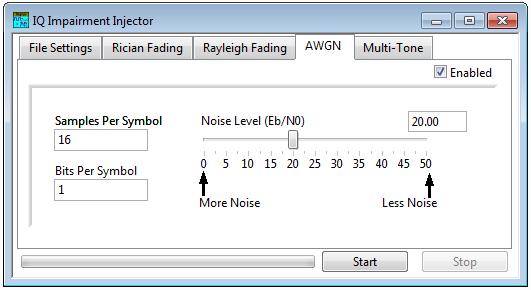
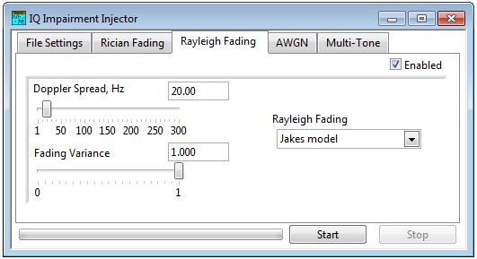
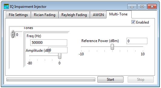
9 Standard Channel Implementation Rician Rayleigh AWGN 9 Multitone

10 Generic models Case Study : octofade System Architecture Emulator Applications GUI n/ac Profile API GSM Profile API WCDMA Profile API LTE Profile API CDMA Profile API WiMAX Profile API Emulator API NI VST Note: greyed out profiles (802.11n/ac, CDMA and WiMAX) will be integrated in the future; n/ac logic currently available in software Altera FPGA board 3GPP Compliant Channel Fader 10 VST = vector signal transceiver
11 Complex Channel Modeling Channel Modeling Antenna Model Platform Dynamics Topography/ Terrain Model Atmospheric Model Motion Trajectory User Inputs Scenarios 3 rd -party Modeling Software IQ File Streaming through Generator Software Modeling Hardware 11

12 NI GPS Simulator Generate 24 hours of up to 12 satellite C/A codes (L1) Achieve automatic satellite simulation from almanac and ephemeris files Define custom motion trajectories for mobile simulation Adjust individual satellite power levels for scenario-specific test Take advantage of manual control of satellite pseudo-range, Doppler, and power-level information Generate WAAS satellites 12
13 Specifications Output Frequency L MHz C/A code Signal Quality Phase Noise: -82 dbc at 100 Hz offset Spurious 2 nd Harmonic: -40dBC max Output 3 rd order distortion: -75dBC typical Power Output -145 dbm to 10 dbm 13


14 Modern Architecture of RADAR Analog RF Section T R M Receiver Front End Transmitter Front End ADC DAC DDC Signal Processing DBF ADBF MTI MTD PC Data Processing MW RWC CFAR Tracker 2B filter KF EKF PF Active Phased Array Antenna Beamsteering Control Weveforms Generation RADAR Console 14

15 RADAR Design, Test and Validation 15
16 Components IF Mixer Filters RF Mixer Power Amplifier Antenna Modulator T/R Switch STALO COHO Limiter processing Video 16
17 Parametric Measurements Modulator Measurements VSWR Isolation Insertion Loss Max Power Switching Time Antenna T/R Switch STALO COHO Limiter processing Video Measurements Sensitivity Selectivity Dynamic range Noise Floor Pulse Mx 17 Measurements VSWR Noise Figure Bandwidth Gain Linearity 1dB Compression IMD/ ToI
Case Study: and Test Wireless Receivers
 Case Study: Using New Technologies to Design and Test Wireless Receivers Agenda Architecture of a receiver Basic GPS Receiver Measurements Case Study 1: GPS Simulation How Testing Works Simulation vs.
RF Receiver Hardware Design
 RF Receiver Hardware Design Bill Sward bsward@rtlogic.com February 18, 2011 Topics Customer Requirements Communication link environment Performance Parameters/Metrics Frequency Conversion Architectures
ni.com The NI PXIe-5644R Vector Signal Transceiver World s First Software-Designed Instrument
 The NI PXIe-5644R Vector Signal Transceiver World s First Software-Designed Instrument Agenda Hardware Overview Tenets of a Software-Designed Instrument NI PXIe-5644R Software Example Modifications Available
TESTING METHODS AND ERROR BUDGET ANALYSIS OF A SOFTWARE DEFINED RADIO By Richard Overdorf
 TESTING METHODS AND ERROR BUDGET ANALYSIS OF A SOFTWARE DEFINED RADIO By Richard Overdorf SDR Considerations Data rates Voice Image Data Streaming Video Environment Distance Terrain High traffic/low traffic
3250 Series Spectrum Analyzer
 The most important thing we build is trust ADVANCED ELECTRONIC SOLUTIONS AVIATION SERVICES COMMUNICATIONS AND CONNECTIVITY MISSION SYSTEMS 3250 Series Spectrum Analyzer > Agenda Introduction
Fast and Accurate RF component characterization enabled by FPGA technology
 Fast and Accurate RF component characterization enabled by FPGA technology Guillaume Pailloncy Senior Systems Engineer Agenda RF Application Challenges What are FPGAs and why are they useful? FPGA-based
Reconfigurable 6 GHz Vector Signal Transceiver with I/Q Interface
 SPECIFICATIONS PXIe-5645 Reconfigurable 6 GHz Vector Signal Transceiver with I/Q Interface Contents Definitions...2 Conditions... 3 Frequency...4 Frequency Settling Time... 4 Internal Frequency Reference...
octofade Channel Emulation
 octofade Channel Emulation January 2014 387 Berlin Road, Bolton, MA 01740 +1.978.222.3114 ๐ info@octoscope.com Outline 2 What is channel emulation and why is it critical for MIMO systems? Channel modeling
Production Test and Spectral Monitoring
 1 Production Test and Spectral Monitoring Stephen Plumb Key RF Building Blocks Symbol Name Types Function Amplifier (2 port) Power Amplifier Low Noise Amplifier Amplify signal before transmission (high
Testing c2k Mobile Stations Using a Digitally Generated Faded Signal
 Testing c2k Mobile Stations Using a Digitally Generated Faded Signal Agenda Overview of Presentation Fading Overview Mitigation Test Methods Agenda Fading Presentation Fading Overview Mitigation Test Methods
Advances in RF and Microwave Measurement Technology
 1 Advances in RF and Microwave Measurement Technology Chi Xu Certified LabVIEW Architect Certified TestStand Architect New Demands in Modern RF and Microwave Test In semiconductor and wireless, technologies
PROPAGATION CHANNEL EMULATOR : ECP
 PROPAGATION CHANNEL EMULATOR : ECP The ECP (Propagation Channel Emulator) synthesizes the principal phenomena of propagation occurring on RF signal links between earth and space. Developed by the R&D laboratory,
RF and Microwave Test and Design Roadshow 5 Locations across Australia and New Zealand
 RF and Microwave Test and Design Roadshow 5 Locations across Australia and New Zealand ni.com Design and test of RADAR systems Agenda Radar Overview Tools Overview VSS LabVIEW PXI Design and Simulation
Advances in RF and Microwave Measurement Technology
 1 Advances in RF and Microwave Measurement Technology Rejwan Ali Marketing Engineer NI Africa and Oceania New Demands in Modern RF and Microwave Test In semiconductor and wireless, technologies such as
CDMA Principle and Measurement
 CDMA Principle and Measurement Concepts of CDMA CDMA Key Technologies CDMA Air Interface CDMA Measurement Basic Agilent Restricted Page 1 Cellular Access Methods Power Time Power Time FDMA Frequency Power
Simulating and Testing of Signal Processing Methods for Frequency Stepped Chirp Radar
 Test & Measurement Simulating and Testing of Signal Processing Methods for Frequency Stepped Chirp Radar Modern radar systems serve a broad range of commercial, civil, scientific and military applications.
GET10B Radar Measurement Basics- Spectrum Analysis of Pulsed Signals. Copyright 2001 Agilent Technologies, Inc.
 GET10B Radar Measurement Basics- Spectrum Analysis of Pulsed Signals Copyright 2001 Agilent Technologies, Inc. Agenda: Power Measurements Module #1: Introduction Module #2: Power Measurements Module #3:
ICNS Design of Integrated Mode S Transponder, ADS-B and Distance Measuring Equipment Transceivers. Omar Yeste, Joe Zambrano and René Jr.
 Design of Integrated Mode S Transponder, ADS-B and Distance Measuring Equipment Transceivers Omar Yeste, Joe Zambrano and René Jr. Landry April 21, 2016 Track 4: Surveillance & Situational Awareness Session
Scalable Front-End Digital Signal Processing for a Phased Array Radar Demonstrator. International Radar Symposium 2012 Warsaw, 24 May 2012
 Scalable Front-End Digital Signal Processing for a Phased Array Radar Demonstrator F. Winterstein, G. Sessler, M. Montagna, M. Mendijur, G. Dauron, PM. Besso International Radar Symposium 2012 Warsaw,
Fundamentals of Arbitrary. Waveform Generation
 Fundamentals of Arbitrary Waveform Generation History Applications Key Specifications Optimization Signal fidelity and dynamic range Embedding and de-embedding Waveform generation and automation software
DESIGN OF A MEASUREMENT PLATFORM FOR COMMUNICATIONS SYSTEMS
 DESIGN OF A MEASUREMENT PLATFORM FOR COMMUNICATIONS SYSTEMS P. Th. Savvopoulos. PhD., A. Apostolopoulos 2, L. Dimitrov 3 Department of Electrical and Computer Engineering, University of Patras, 265 Patras,
Bridge RF Design and Test Applications with NI SDR Platforms
 Bridge RF Design and Test Applications with NI SDR Platforms Jason Strydom Application Engineer National Instruments - Midrand The National Instruments Vision To do for test and measurement what the spreadsheet
What s Behind 5G Wireless Communications?
 What s Behind 5G Wireless Communications? Marc Barberis 2015 The MathWorks, Inc. 1 Agenda 5G goals and requirements Modeling and simulating key 5G technologies Release 15: Enhanced Mobile Broadband IoT
Advanced RF Measurements You Didn t Know Your Oscilloscope Could Make. Brad Frieden Philip Gresock
 Advanced RF Measurements You Didn t Know Your Oscilloscope Could Make Brad Frieden Philip Gresock Agenda RF measurement challenges Oscilloscope platform overview Typical RF characteristics Bandwidth vs.
High-end vector signal generator creates complex multichannel scenarios
 Wireless technologies Signal generation and analysis High-end vector signal generator creates complex multichannel scenarios Fig. 1: The new R&S SMW200A vector signal generator combined with two R&S SGS100A
Spectral Monitoring/ SigInt
 RF Test & Measurement Spectral Monitoring/ SigInt Radio Prototyping Horizontal Technologies LabVIEW RIO for RF (FPGA-based processing) PXI Platform (Chassis, controllers, baseband modules) RF hardware
2015 The MathWorks, Inc. 1
 2015 The MathWorks, Inc. 1 What s Behind 5G Wireless Communications? 서기환과장 2015 The MathWorks, Inc. 2 Agenda 5G goals and requirements Modeling and simulating key 5G technologies Release 15: Enhanced Mobile
TestData Summary of 5.2GHz WLAN Direct Conversion RF Transceiver Board
 Page 1 of 16 ========================================================================================= TestData Summary of 5.2GHz WLAN Direct Conversion RF Transceiver Board =========================================================================================
Radio with COTS Technologies. ATE Systems Engineer
 Signal Intelligence and Software-Defined Radio with COTS Technologies Sacha Emery ATE Systems Engineer 1 Agenda Introduction Optimised signal processing with multicore and FPGAs Timing and synchronisation
RF 파워앰프테스트를위한 Envelope Tracking 및 DPD 기술
 RF 파워앰프테스트를위한 Envelope Tracking 및 DPD 기술 한국내쇼날인스트루먼트 RF 테스트담당한정규 jungkyu.han@ni.com Welcome to the World of RFICs Low Noise Amplifiers Power Amplifiers RF Switches Duplexer and Filters 2 Transmitter Power
RF and Microwave Test and Design Roadshow Cape Town & Midrand
 RF and Microwave Test and Design Roadshow Cape Town & Midrand Advanced PXI Technologies Signal Recording, FPGA s, and Synchronization Philip Ehlers Outline Introduction to the PXI Architecture PXI Data
3GPP Radio Prototyping Using Radio420X. Technical Article. 3GPP Radio Prototyping Using Radio420X. nutaq.com
 Technical Article 3GPP Radio Prototyping Using Radio420X 1 3GPP Radio Prototyping Using Radio420X Written by M. Ahmed Ouameur, PhD, MBA Abstract This application note addresses 3GPP radio design and prototyping
Fully integrated UHF RFID mobile reader with power amplifiers using System-in-Package (SiP)
") Fully integrated UHF RFID mobile reader with power amplifiers using System-in-Package (SiP) Hyemin Yang 1, Jongmoon Kim 2, Franklin Bien 3, and Jongsoo Lee 1a) 1 School of Information and Communications,
Fully integrated UHF RFID mobile reader with power amplifiers using System-in-Package (SiP) Hyemin Yang 1, Jongmoon Kim 2, Franklin Bien 3, and Jongsoo Lee 1a) 1 School of Information and Communications,
BANDWIDTH EFFICIENT TURBO CODING FOR HIGH SPEED MOBILE SATELLITE COMMUNICATIONS
 BANDWIDTH EFFICIENT TURBO CODING FOR HIGH SPEED MOBILE SATELLITE COMMUNICATIONS S. Adrian BARBULESCU, Wade FARRELL Institute for Telecommunications Research, University of South Australia, Warrendi Road,
TSEK38 Radio Frequency Transceiver Design: Project work B
 TSEK38 Project Work: Task specification A 1(15) TSEK38 Radio Frequency Transceiver Design: Project work B Course home page: Course responsible: http://www.isy.liu.se/en/edu/kurs/tsek38/ Ted Johansson (ted.johansson@liu.se)
5G Multi-Band Vector Transceiver
 SOLUTION BRIEF Streamlining high-volume test of 5G NR base stations 5G Multi-Band Vector Transceiver Compact, scalable solution accelerates deployment of 5G equipment 5G New Radio (NR) network equipment
Making Noise in RF Receivers Simulate Real-World Signals with Signal Generators
 Making Noise in RF Receivers Simulate Real-World Signals with Signal Generators Noise is an unwanted signal. In communication systems, noise affects both transmitter and receiver performance. It degrades
Receiver Design. Prof. Tzong-Lin Wu EMC Laboratory Department of Electrical Engineering National Taiwan University 2011/2/21
 Receiver Design Prof. Tzong-Lin Wu EMC Laboratory Department of Electrical Engineering National Taiwan University 2011/2/21 MW & RF Design / Prof. T. -L. Wu 1 The receiver mush be very sensitive to -110dBm
Digital Signal Analysis
 Digital Signal Analysis Objectives - Provide a digital modulation overview - Review common digital radio impairments Digital Modulation Overview Signal Characteristics to Modify Polar Display / IQ Relationship
Supplemental Slides: MIMO Testbed Development at the MPRG Lab
 Supplemental Slides: MIMO Testbed Development at the MPRG Lab Raqibul Mostafa Jeffrey H. Reed Slide 1 Overview Space Time Coding (STC) Overview Virginia Tech Space Time Adaptive Radio (VT-STAR) description:
Full Duplex Radios. Sachin Katti Kumu Networks & Stanford University 4/17/2014 1
 Full Duplex Radios Sachin Katti Kumu Networks & Stanford University 4/17/2014 1 It is generally not possible for radios to receive and transmit on the same frequency band because of the interference that
Enabling Future Wireless Technology Research through Flexible & Modular Platforms
 Enabling Future Wireless Technology Research through Flexible & Modular Platforms Richard Silley Business Development Manager RF & Communications Evolution of Wireless Communications How can we increase
VST 6 GHz RF Vector Signal Transceiver (VST)
") VST 6 GHz RF Vector Signal Transceiver (VST) 2016 Datasheet The most important thing we build is trust Key features Vector signal analyser and generator in a single 3U x 3 slot wide PXIe module 65 MHz
VST 6 GHz RF Vector Signal Transceiver (VST) 2016 Datasheet The most important thing we build is trust Key features Vector signal analyser and generator in a single 3U x 3 slot wide PXIe module 65 MHz
Nutaq Radio420X Multimode SDR FMC RF transceiver PRODUCT SHEET
 Nutaq Radio420X Multimode SDR FMC RF transceiver PRODUCT SHEET RoHS QUEBEC I MONTREAL I NEW YORK I nutaq.com Nutaq Radio420X SISO, dual-band and 2x2 MIMO RF transceivers Wide frequency range 300 MHz 3
Application Note. Device Test Proposal. MS269xA Signal Analyzer
 Application Note Device Test Proposal MS269xA Signal Analyzer MS269xA Signal Analyzer MS269xA-020 Vector Signal Generator (Option) Device Test Proposal Anritsu Corporation Slide 1 MS269xA Signal Analyzer
Measuring Non-linear Amplifiers
 Measuring Non-linear Amplifiers Transceiver Components & Measuring Techniques MM3 Jan Hvolgaard Mikkelsen Radio Frequency Integrated Systems and Circuits Division Aalborg University 27 Agenda Non-linear
Why/When I need a Spectrum Analyzer. Jan 12, 2017
 Why/When I need a Jan 12, 2017 Common Questions What s the difference of Oscilloscope and Spectrum Analysis Almost all Oscilloscope has FFT for a spectrum view, why I need a spectrum analyzer? When shall
Redefining RF Instrumentation
 Redefining RF Instrumentation Agenda Introduction RF Platform PXI Architecture NI FPGA Platform RF Instrumentation redefined Wireless Everywhere The proliferation of mobile devices, including smartphones
Nutaq Radio420X I MONTREAL I NEW YORK I. Multimode SDR FMC RF transceiver PRODUCT SHEET. RoHS. nutaq.com QUEBEC
 Nutaq Radio420X Multimode SDR FMC RF transceiver PRODUCT SHEET RoHS QUEBEC I MONTREAL I NEW YORK I nutaq.com Nutaq Radio420X SISO, dual-band and 2x2 MIMO RF transceivers Wide frequency range 300 MHz 3.8
RF and Microwave Test and Design Roadshow 5 Locations across Australia and New Zealand
 RF and Microwave Test and Design Roadshow 5 Locations across Australia and New Zealand Advanced PXI Technologies Signal Recording, FPGA s, and Synchronization Outline Introduction to the PXI Architecture
PXI Modules 3066 PXI Multi-Way Active RF Combiner Data Sheet
 PXI Modules 3066 PXI Multi-Way Active RF Combiner Data Sheet The most important thing we build is trust 250 MHz to 6 GHz RF signal conditioning module for multi- UE, MIMO and Smartphone testing Four full
Software Defined Radio in Ham Radio Dennis Silage K3DS TS EPA Section ARRL
 Software Defined Radio in Ham Radio Dennis Silage K3DS silage@arrl.net TS EPA Section ARRL TUARC K3TU SDR in HR The crystal radio was once a simple introduction to radio electronics and Amateur Radio.
Wireless Communication Systems: Implementation perspective
 Wireless Communication Systems: Implementation perspective Course aims To provide an introduction to wireless communications models with an emphasis on real-life systems To investigate a major wireless
VIAVI VST. Data Sheet. 6 GHz RF Vector Signal Transceiver (VST)
") Data Sheet VIAVI 6 GHz RF Vector Signal Transceiver () VIAVI Solutions The Vector Signal Transceiver () is an essential building block in RF communications test solutions supplied by VIAVI Solutions. Overview
Data Sheet VIAVI 6 GHz RF Vector Signal Transceiver () VIAVI Solutions The Vector Signal Transceiver () is an essential building block in RF communications test solutions supplied by VIAVI Solutions. Overview
PXI LTE/LTE-A Downlink (FDD and TDD) Measurement Suite Data Sheet
 Measurement Suite Data Sheet") PXI LTE/LTE-A Downlink (FDD and TDD) Measurement Suite Data Sheet The most important thing we build is trust Designed for the production test of the base station RF, tailored for the evolving small cell
PXI LTE/LTE-A Downlink (FDD and TDD) Measurement Suite Data Sheet The most important thing we build is trust Designed for the production test of the base station RF, tailored for the evolving small cell
Faculty of Information Engineering & Technology. The Communications Department. Course: Advanced Communication Lab [COMM 1005] Lab 6.
![Faculty of Information Engineering & Technology. The Communications Department. Course: Advanced Communication Lab [COMM 1005] Lab 6.](/thumbs/90/102233011.jpg "Faculty of Information Engineering & Technology. The Communications Department. Course: Advanced Communication Lab [COMM 1005] Lab 6.") Faculty of Information Engineering & Technology The Communications Department Course: Advanced Communication Lab [COMM 1005] Lab 6.0 NI USRP 1 TABLE OF CONTENTS 2 Summary... 2 3 Background:... 3 Software
Faculty of Information Engineering & Technology The Communications Department Course: Advanced Communication Lab [COMM 1005] Lab 6.0 NI USRP 1 TABLE OF CONTENTS 2 Summary... 2 3 Background:... 3 Software
Multi-Signal, Multi-Format Analysis With Agilent VSA Software
 Multi-Signal, Multi-Format Analysis With Agilent 89600 VSA Software Ken Voelker Agilent Technologies Inc. April 2012 1 April, 25 2012 Agenda Introduction: New Measurement Challenges Multi-Measurements
TRANSCOM Manufacturing & Education
 www.transcomwireless.com 1 G6 Vector Signal Generator Overview G6 Vector Signal Generator is a high performance vector signal generator. It can generate arbitrary wave signal, continuous wave signal, common
Propsim C8 MIMO Extension. 4x4 MIMO Radio Channel Emulation
 Propsim C8 MIMO Extension 4x4 MIMO Radio Channel Emulation Propsim C8 provides a flexible platform for Multiple Input Multiple Output (MIMO) development and evaluation. With a maximum number of 16 independent
G6M VSG Module and A6M VSA Module
 Models ready for System Integration G6M VSG Module and A6M VSA Module Transcom Instruments Overview of G6M G6M vector signal generator module is a high performance vector signal generator. It supports
Vector Signal Generator Module. Transcom Instruments.
 Vector Signal Generator Module G6 Transcom Instruments Overview of G6 G6 vector signal generator module is a high performance vector signal generator. It supports arbitrary wave signal, continuous wave
Getting Started Guide
 MaxEye IEEE 0.15.4 UWB Measurement Suite Version 1.0.0 Getting Started Guide 1 Table of Contents 1. Introduction... 3. Installed File Location... 3 3. Programming Examples... 4 3.1. 0.15.4 UWB Signal Generation...
Advances in RF and Microwave Measurement Technology
 1 Advances in RF and Microwave Measurement Technology Farris Alhorr Business Development Manager RF & Wireless Communication Farris.alhorr@ New Demands in Modern RF and Microwave Test In semiconductor
Understanding Low Phase Noise Signals. Presented by: Riadh Said Agilent Technologies, Inc.
 Understanding Low Phase Noise Signals Presented by: Riadh Said Agilent Technologies, Inc. Introduction Instabilities in the frequency or phase of a signal are caused by a number of different effects. Each
Introduction to Global Navigation Satellite System (GNSS) Signal Structure
 Signal Structure") Introduction to Global Navigation Satellite System (GNSS) Signal Structure Dinesh Manandhar Center for Spatial Information Science The University of Tokyo Contact Information: dinesh@iis.u-tokyo.ac.jp
Introduction to Global Navigation Satellite System (GNSS) Signal Structure Dinesh Manandhar Center for Spatial Information Science The University of Tokyo Contact Information: dinesh@iis.u-tokyo.ac.jp
Reinventing the Transmit Chain for Next-Generation Multimode Wireless Devices. By: Richard Harlan, Director of Technical Marketing, ParkerVision
 Reinventing the Transmit Chain for Next-Generation Multimode Wireless Devices By: Richard Harlan, Director of Technical Marketing, ParkerVision Upcoming generations of radio access standards are placing
Analog Devices Welcomes Hittite Microwave Corporation NO CONTENT ON THE ATTACHED DOCUMENT HAS CHANGED
 Analog Devices Welcomes Hittite Microwave Corporation NO CONTENT ON THE ATTACHED DOCUMENT HAS CHANGED www.analog.com www.hittite.com THIS PAGE INTENTIONALLY LEFT BLANK 17 Product Application Notes Introduction
Smart Energy Solutions for the Wireless Home
 Smart Energy Solutions for the Wireless Home Advanced Metering Infrastructure (AMI) ZigBee (IEEE 802.15.4) Wireless Local Area Networks (WLAN) Industrial and Home Control Plug-in Hybrid Electric Vehicles
Testing RFIC Power Amplifiers with Envelope Tracking. April 2014
 Testing RFIC Power Amplifiers with Envelope Tracking April 2014 1 Agenda Key Test Challenges Addressing Test Challenges New emerging technologies such as envelope tracking and DPD and their implications
TRANSCOM Manufacturing & Education. Transcom Instruments. Product Brochure TRANSCOM INSTRUMENTS. Product Brochure.
 TRANSCOM INSTRUMENTS Product Brochure Transcom Instruments Product Brochure www.transcomwireless.com 1 Vector Signal Generator Overview Vector Signal Generator is a high performance vector signal generator.
Today s mobile devices
 PAGE 1 NOVEMBER 2013 Highly Integrated, High Performance Microwave Radio IC Chipsets cover 6-42 GHz Bands Complete Upconversion & Downconversion Chipsets for Microwave Point-to-Point Outdoor Units (ODUs)
High Speed & High Frequency based Digital Up/Down Converter for WCDMA System
 High Speed & High Frequency based Digital Up/Down Converter for WCDMA System Arun Raj S.R Department of Electronics & Communication Engineering University B.D.T College of Engineering Davangere-Karnataka,
Bridging the Gap between System & Circuit Designers
 Bridging the Gap between System & Circuit Designers October 27, 2004 Presented by: Kal Kalbasi Q & A Marc Petersen Copyright 2003 Agilent Technologies, Inc. The Gap System Communication System Design System
Today s communication
 From October 2009 High Frequency Electronics Copyright 2009 Summit Technical Media, LLC Selecting High-Linearity Mixers for Wireless Base Stations By Stephanie Overhoff Maxim Integrated Products, Inc.
ELT Radio Architectures and Signal Processing. Motivation, Some Background & Scope
 Introduction ELT-44007/Intro/1 ELT-44007 Radio Architectures and Signal Processing Motivation, Some Background & Scope Markku Renfors Department of Electronics and Communications Engineering Tampere University
Using a design-to-test capability for LTE MIMO (Part 1 of 2)
") Using a design-to-test capability for LTE MIMO (Part 1 of 2) System-level simulation helps engineers gain valuable insight into the design sensitivities of Long Term Evolution (LTE) Multiple-Input Multiple-Output
Using a design-to-test capability for LTE MIMO (Part 1 of 2) System-level simulation helps engineers gain valuable insight into the design sensitivities of Long Term Evolution (LTE) Multiple-Input Multiple-Output
Getting Started Guide
 MaxEye ZigBee (IEEE 802.15.4) Measurement Suite Version 1.0.5.3 Getting Started Guide Table of Contents 1. Introduction...3 2. Installed File Location...3 3. Soft Front Panel...5 3.1 MaxEye ZigBee Signal
SPEC. Intelligent EW Systems for Complex Spectrum Operations ADEP. ADEP Product Descriptions
 Intelligent EW Systems for Complex Spectrum Operations ADEP TM Dynamic Engagement Products for Configurable Operational Response & Advanced Range Solutions ADEP Product Descriptions SPEC SPEC ADEP Overview
Keysight Technologies
 Keysight Technologies Generating Signals Basic CW signal Block diagram Applications Analog Modulation Types of analog modulation Block diagram Applications Digital Modulation Overview of IQ modulation
Transmitter Design and Measurement Challenges
 Transmitter Design and Measurement Challenges Based on the book: LTE and the Evolution to 4G Wireless Chapter 6.4 4G World 2009 presented by: David L. Barner www/agilent.com/find/4gworld 1 Agilent Technologies,
LTE Radio Channel Emulation for LTE User. Equipment Testing
 LTE 7100 Radio Channel Emulation for LTE User Equipment Testing Fading and AWGN option for 7100 Digital Radio Test Set Meets or exceeds all requirements for LTE fading tests Highly flexible with no manual
9 Best Practices for Optimizing Your Signal Generator Part 2 Making Better Measurements
 9 Best Practices for Optimizing Your Signal Generator Part 2 Making Better Measurements In consumer wireless, military communications, or radar, you face an ongoing bandwidth crunch in a spectrum that
Sigfox RF & Protocol Test Plan for RC2-UDL-ENC
 Version 380 September 14, 2018 Sigfox RF & Protocol Test Plan for RC2-UDL-ENC Public Use Note: Only the last version of this document available on the Sigfox web sites is official and applicable This document
CLOUDSDR RFSPACE #CONNECTED SOFTWARE DEFINED RADIO. final design might vary without notice
 CLOUDSDR #CONNECTED SOFTWARE DEFINED RADIO final design might vary without notice 1 - PRELIMINARY SPECIFICATIONS http://www.rfspace.com v0.1 RFSPACE CloudSDR CLOUDSDR INTRODUCTION The RFSPACE CloudSDR
Session 3. CMOS RF IC Design Principles
 Session 3 CMOS RF IC Design Principles Session Delivered by: D. Varun 1 Session Topics Standards RF wireless communications Multi standard RF transceivers RF front end architectures Frequency down conversion
Software Radio, GNU Radio, and the USRP Product Family
 Software Radio, GNU Radio, and the USRP Product Family Open Hardware for Software Radio Matt Ettus, matt@ettus.com Software Radio Simple, general-purpose hardware Do as much as possible in software Everyone's
Parallel Channel Sounder for MIMO Communications
 Parallel Channel Sounder for MIMO Communications Wuxiong ZHANG, Ph.D., Associate Professor SHanghai Institute of Fog CompuTing (SHIFT) Shanghai Research Center for Wireless COmmunications (WiCO) Shanghai
LitePoint IQnxn MIMO Test Solution
 DATA SHEET LitePoint IQnxn MIMO Test Solution 2011 LitePoint Corporation. All rights reserved. Revision History Release Date Revision Change Description Jan 20, 2006 1.0 First Release April 6, 2007 2.1
IQ2015 TM Connectivity Test System
 TECHNICAL SPECIFICATIONS IQ2015 TM Connectivity Test System 2014 LitePoint, A Teradyne Company. All rights reserved. General Technical Specifications Analyzer Parameter Port Designations Range Input frequency
Transcom Instruments. Product Brochure TRANSCOM INSTRUMENTS. Product Brochure
 TRANSCOM INSTRUMENTS Product Brochure Transcom Instruments Product Brochure Micro-Tx Vector Signal Generator Module Overview Micro-Tx vector signal generator module is a high performance vector signal
Understanding RF and Microwave Analysis Basics
 Understanding RF and Microwave Analysis Basics Kimberly Cassacia Product Line Brand Manager Keysight Technologies Agenda µw Analysis Basics Page 2 RF Signal Analyzer Overview & Basic Settings Overview
Keysight Technologies PXIe Measurement Accelerator Speeds RF Power Amplifier Test
 Keysight Technologies PXIe Measurement Accelerator Speeds Power Amplifier Test Article Reprint Microwave Journal grants Keysight Technologies permission to reprint the article PXIe Measurement Accelerator
Simulation for 5G New Radio System Design and Verification
 Simulation for 5G New Radio System Design and Verification WHITE PAPER The Challenge of the First Commercial 5G Service Deployment The 3rd Generation Partnership Project (3GPP) published its very first
TSEK38: Radio Frequency Transceiver Design Lecture 7: Receiver Synthesis (II)
") TSEK38: Radio Frequency Transceiver Design Lecture 7: Receiver Synthesis (II) Ted Johansson, ISY ted.johansson@liu.se Systematic Receiver Synthesis (II) 4.3 Intermodulation characteristics Phase noise
TSEK38: Radio Frequency Transceiver Design Lecture 7: Receiver Synthesis (II) Ted Johansson, ISY ted.johansson@liu.se Systematic Receiver Synthesis (II) 4.3 Intermodulation characteristics Phase noise
HFA GHz - 2.5GHz 250mW Power Amplifier. Description. Features. Applications. Ordering Information. Functional Block Diagram
 SEMICONDUCTOR HFA39 January 1997 2.4GHz - 2.GHz mw Power Amplifier Features Highly Integrated Power Amplifier with T/R Switch Operates Over 2.7V to Supply Voltage High Linear Output Power (P 1dB : +24dBm)
PAR4CR: THE DEVELOPMENT OF A NEW SDR-BASED PLATFORM TOWARDS COGNITIVE RADIO
 PAR4CR: THE DEVELOPMENT OF A NEW SDR-BASED PLATFORM TOWARDS COGNITIVE RADIO Olga Zlydareva Co-authors: Martha Suarez Rob Mestrom Fabian Riviere Outline 1 Introduction System Requirements Methodology System
Challenges of 5G mmwave RF Module. Ren-Jr Chen M300/ICL/ITRI 2018/06/20
 Challenges of 5G mmwave RF Module Ren-Jr Chen rjchen@itri.org.tw M300/ICL/ITRI 2018/06/20 Agenda 5G Vision and Scenarios mmwave RF module considerations mmwave RF module solution for OAI Conclusion 2 5G
Propagation Channel Emulator ECP-70
 1 product description The ECP (Propagation Channel Emulator 70) synthesizes the principal phenomena of propagation occurring on RF signal links between earth and space. Developed by the R&D laboratory,
Multipath Mitigation Algorithm Results using TOA Beacons for Integrated Indoor Navigation
 Multipath Mitigation Algorithm Results using TOA Beacons for Integrated Indoor Navigation ION GNSS 28 September 16, 28 Session: FOUO - Military GPS & GPS/INS Integration 2 Alison Brown and Ben Mathews,
ADI 2006 RF Seminar. Chapter II RF/IF Components and Specifications for Receivers
 ADI 2006 RF Seminar Chapter II RF/IF Components and Specifications for Receivers 1 RF/IF Components and Specifications for Receivers Fixed Gain and Variable Gain Amplifiers IQ Demodulators Analog-to-Digital