MICROWAVES Introduction to Laboratory Classes
|
|
|
- Clare Andrea Chandler
- 6 years ago
- Views:
Transcription

1 MEEC, 1 st semester 2011/2012 DEEC MICROWAVES Introdution to Laboratory Classes Custódio Peixeiro
2 Laboratory Classes 4 Sessions T1 Contat with a mirowave benh T2 Mathing on an impedane load T4 Measurement of the S-parameters of a waveguide T - juntion T5 Measurement of dieletri properties of materials Classes onentrated in 4 weeks (separated 4 weeks) T September T Otober T November T Deember 2
3 Maximum duration: 3 hours 2 students per group (few exeptions with 3 students) 5 groups per lass (5 benhes) On-line registrations in Fénix (from 15h30 September 13 until 23h59 September 15) Support to students on the days of the laboratory lasses, 15h30-17h00, room North Tower (ext. 2167) Classes start next week (19 September) 3
4 Evaluation Marks Final Mark = 70% Written Exam Mark + 30% Laboratory Mark Laboratory Mark = 50% Oral Evaluation Mark + 50% Written Report Mark Witten Exam Mark individual (0 to 20) Oral Evaluation Mark individual (0 to 10) Written Report Mark group (0 to 10) 4
 with retangular metalli")
5 Mirowave Benh Students use a mirowave didati benh (X band: 8-12 GHz) with retangular metalli waveguide 5

6 6
7 Reports Editor Use of the desktop omputer available in eah benh to write the session report Fixed template for eah session report The templates follow the laboratory guide (Portuguese version available in Seção de Folhas, AEIST) Report printing at the end of the lass Report marks given two weeks after the last lass of eah session 7
8 Important Notes It is absolutely neessary to prepare the laboratory sessions by reading the orresponding guide. If you don t do that usually you will not be able to finish the session. Always follow thoroughly the safety reommendations given in the first session Although low power is used (10 mw) mirowaves radiation hazards must be avoided Always follow the handling reommendation given in the first session to handle the omponents and equipment with are Very expensive and fragile equipment 8
9 Take a USB flash drive to eah lass to store the report Register in paper all the results obtained Download the evaluation reord sheet file from the Fénix web page, print it and take it (with name and photo of eah student) for the first session Take a alulator for every session The lasses start at the indiated time (08h00 or 17h00) and FINISH at the indiate time (11h00 or 20h00) 9
10 Transmission Line Basis As already indiated the mirowave benh uses metalli retangular waveguide omponents TE (transversal eletri) and TM (transversal magneti) modes are defined for the metalli retangular waveguide The fundamental mode of the metalli retangular waveguide (ab) is the TE 10 (a > b). The orresponding utoff frequeny is f TE10 2a λ z TE 10 1 λ λ 2a 2 10
11 11
12 Eah waveguide mode an be represented by equivalent voltage and urrent (fititious) distributions Transmission line theory an be used to study the field distribution along the mirowave benh Z g I 1 I 2 V g V 1 Z 0 V 2 Z -l 0 z 12
13 V(z) I(z) Vi (z) Ii(z) Vr (z) Ir(z) 1 Z o Vi (Vi jk z jk z 2 e Vr2 e 2 e jk z Vr 2 e jk z ) Γ Vr Vi 2 jθ Γ e 2 Load (voltage) refletion oeffiient V(z) I(z) Vi Vi Z 2 (e (e jk z Γe Γe jk z 2 jk z jk z o Vi 2 V2 Z I2 Vi 2 (1 Γ) Z (1 Γ) Z ) ) o z Z Z o 1Γ 1Γ Γ z z 1 1 y 1 1 y Γ I Γ y y
14 Z 1 V(z l) I(z l) Z o e e jkl jk l Γe Γe jk l jk l Z o Z Z o jz jz o tan(kl) tan(kl) z 1 Z Z 1 o z 1 j tan( k l) j z tan( k l) Γ(z) Vr Vi Vr Vi jk z 2 e j2k z Γe jk z 2 e Voltage standing wave ratio (VSWR) Refletion oeffiient along the line VSWR V V max min 1 1 Γ Γ Γ VSWR VSWR 1 1 Γ 0,1 VSWR [1, [ In spae and time Download VSWR.EXE from Fénix web page V(z,t) Vi 2[os (ωt kz) Γ os (ωt kzθ)] 14
15 Smith Chart 15 jx r z 1 z 1 z e Γ Γ jθ b j g y 1 y 1 y e Γ Γ jθ I I I π θ θ Γ Γ I I Re ( or I ) Im ( or I ) 1 (r + j x) I (g + jb) or I
 4.")
16 Example Z = 25 + j 50 Zo = 50 z = j 1 y= 0.4 j 0.8 Γ 0.62 e j 0.46 π VSWR = 4.27 Γ db 20 log (0.62) 4.15dB 16
17 Impedane Mathing with Stub d Z 0 Z y y y s lim lim lim z d (from right) z d (from left) z' l s y s (z') y (z) y (z) l s Z 0 0 z y ( g ( g s s g jb g s jb ) ( g ) j(b y s s b y jb ) ) Goal is y - = 1 + j 0 (perfet mathing) g bs s g b 1 0 b s g 1 b b s otan(kl s ) b 17
=0.293 lsa / = (0.340-0.250) = 0.090 db / = (0.115+0.322)=0.437 lsb / = (0.250+0.160)=0.")
18 Example Z = 25 + j 50 Zo = 50 z = j 1 y= 0.4 j 0.8 Two solutions (a, b) da / = ( )=0.293 lsa / = ( ) = db / = ( )=0.437 lsb / = ( )=
19 Input Refletion Coeffiient [db] Solutions a and b are equivalent ( = 0 = - db, VSWR = 1) at entral frequeny (but) have different bandwidths (BW) For VSWR 2 ( db) Solution a BW = 16.2 % Solution b BW = 8.1 % ,7 0,8 0,9 1 1,1 1,2 1,3 Normalized Frequeny Solution a Solution b 19
20 VSWR Several other speifiations may be used VSWR db VSWR db 5 4,5 4 3,5 3 2,5 2 1,5 1 0,7 0,8 0,9 1 1,1 1,2 1,3 Normalized Frequeny Solution a Solution b 20
21 RF Virtual (Software Tool) Down load the software tool from the Fénix web page Basi setup (T1) Choose frequeny and type of load Inlude (or not) slide srew tuner Visualization of the VSWR meter measurement Can be very useful to prepare T1 and T2 21

22 22
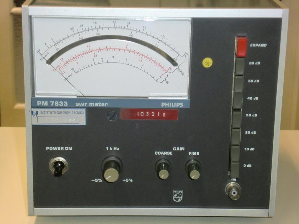
23 VSWR Meter It is a dediated equipment to measure diretly the VSWR in the slotted waveguide Tuned (1 khz) amplifier and voltmeter Calibration needed eah time the load onditions are hanged Pointer defletion (stronger voltage) lokwise Very important to learn you to use it 23

24 24

25 25
26 VSWR Measurement Proedure 1. Move the probe arriage to the right limit of the slotted waveguide (losest to the load) 2. Move the probe arriage slowly to the left until you find a maximum 3. Adjust the gain (use the buttons for 10 db steps and the knob for ontinuous adjustment) until the meter indiates 1.0 on the upper sale 4. Move the probe arriage to a minimum Move to the right if in 2 you have passed a minimum and to the left otherwise Do not hange the gain 26
27 5. Read the VSWR diretly in the upper sale (1 - ) 6. If VSWR > 4 then inrease the gain 10 db and read the VSWR in the seond sale (3.2 10) 7. If VSWR > 10 then inrease the gain 10 db again, read the VSWR in the first sale and multiply by If VSWR > 40 then inrease the gain 10 db again, read the VSWR in the seond sale and multiply by You an ontinue this inrease of gain and hange of sale proedure if needed (VSWR > 100) 10. The third (red) sale is used to obtain more aurate measurements when VSWR 1.3. In that ase you need to press the (red) EXPAND button. 27
Transmission Lines: Coaxial Cables and Waveguides
 Transmission Lines: Coaxial Cables and Waveguides Jason ClIItis 1 April 8, 00 1. Introdution This pap er investigates the wave veloities in oaxial ables and retangular waveguides. Coaxial ables and waveguides
Analysis and Design of an UWB Band pass Filter with Improved Upper Stop band Performances
 Analysis and Design of an UWB Band pass Filter with Improved Upper Stop band Performanes Nadia Benabdallah, 1 Nasreddine Benahmed, 2 Fethi Tari Bendimerad 3 1 Department of Physis, Preparatory Shool of
Homework: Please number questions as numbered on assignment, and turn in solution pages in order.
 ECE 5325/6325: Wireless Communiation Systems Leture Notes, Spring 2010 Leture 6 Today: (1) Refletion (2) Two-ray model (3) Cellular Large Sale Path Loss Models Reading for today s leture: 4.5, 4.6, 4.10.
UNIT -4 (Guided waves between Parallel planes)
") SRI VENKATESWARA COLLEGE OF ENGINEERING DEPARTMENT OF ELECTRONICS AND COMMUNICATION ENGINEERING Date : 09.09.014 PART-A QUESTIONS AND ANSWERS Subjet : Transmission lines & Wave Guides Sub Code : EC305
SRI VENKATESWARA COLLEGE OF ENGINEERING DEPARTMENT OF ELECTRONICS AND COMMUNICATION ENGINEERING Date : 09.09.014 PART-A QUESTIONS AND ANSWERS Subjet : Transmission lines & Wave Guides Sub Code : EC305
Filters. A RF/microwave filter is (typically) a passive, reciprocal, 2- port linear device. Filter
 a passive, reciprocal, 2- port linear device. Filter") 3/1/25 Filters.do 1/8 Filters A RF/mirowave filter is (typially) a passive, reiproal, 2- port linear devie. Pin Filter Pout If port 2 of this devie is terminated in a mathed load, then we an relate the
3/1/25 Filters.do 1/8 Filters A RF/mirowave filter is (typially) a passive, reiproal, 2- port linear devie. Pin Filter Pout If port 2 of this devie is terminated in a mathed load, then we an relate the
A 24 GHz Band FM-CW Radar System for Detecting Closed Multiple Targets with Small Displacement
 A 24 GHz Band FM-CW Radar System for Deteting Closed Multiple Targets with Small Displaement Kazuhiro Yamaguhi, Mitsumasa Saito, Takuya Akiyama, Tomohiro Kobayashi and Hideaki Matsue Tokyo University of
Notes on Dielectric Characterization in Waveguide
 Notes on Dieletri Charaterization in Waveguide R.Nesti, V. Natale IRA-INAF Aretri Astrophysial Observatory 1. Theory Let's suppose we have to haraterize the eletromagneti properties of a dieletri material,
RF Link Budget Calculator Manual
 RF Link Budget Calulator Manual Author Ivo van Ling for www.vanling.net Software Release RF Link Distane Calulator, Version 1.00, Dated 4 January 2010 Manual Version 1.00 Date 19-01-2010 Page: 1(8) Contents
Characterization of the dielectric properties of various fiberglass/epoxy composite layups
 Charaterization of the dieletri properties of various fiberglass/epoxy omposite layups Marotte, Laurissa (University of Kansas); Arnold, Emily Center for Remote Sensing of Ie Sheets, University of Kansas
Revision: April 18, E Main Suite D Pullman, WA (509) Voice and Fax
 Voice and Fax") Lab 9: Steady-state sinusoidal response and phasors Revision: April 18, 2010 215 E Main Suite D Pullman, WA 99163 (509) 334 6306 Voie and Fax Overview In this lab assignment, we will be onerned with the
Lab 9: Steady-state sinusoidal response and phasors Revision: April 18, 2010 215 E Main Suite D Pullman, WA 99163 (509) 334 6306 Voie and Fax Overview In this lab assignment, we will be onerned with the
Compact Band-Pass and Band-Reject Microwave Filters Using Partial H-Plane Waveguide and Dielectric Layers
 Compat Band-Pass and Band-Rejet Mirowave Filters Using ial H-Plane Waveguide and Dieletri ayers A. Ghajar Department of Eletrial Engineering University of Guilan Rasht, Iran alighajar199@gmail.om H. Ghorbaninejad-Foumani
We are IntechOpen, the world s leading publisher of Open Access books Built by scientists, for scientists. International authors and editors
 We are IntehOpen, the world s leading publisher of Open Aess books Built by sientists, for sientists 3,800 6,000 10M Open aess books available International authors and editors Downloads Our authors are
Microwave Circuit Design and Measurements Lab. INTRODUCTION TO MICROWAVE MEASUREMENTS: DETECTION OF RF POWER AND STANDING WAVES Lab #2
 EE 458/558 Microwave Circuit Design and Measurements Lab INTRODUCTION TO MICROWAVE MEASUREMENTS: DETECTION OF RF POWER AND STANDING WAVES Lab #2 The purpose of this lab is to gain a basic understanding
Transmission Line Fundamentals
 ransmission Line Fundamentals b Chris Angove DISCLAIMER he Author makes no representation or warranties with respet to the aura or ompleteness of the ontents of this paper and speifiall dislaims an implied
Objectives. Presentation Outline. Digital Modulation Lecture 04
 Digital Modulation Leture 04 Filters Digital Modulation Tehniques Rihard Harris Objetives To be able to disuss the purpose of filtering and determine the properties of well known filters. You will be able
A compact dual-band bandpass filter using triple-mode stub-loaded resonators and outer-folding open-loop resonators
 Indian Journal of Engineering & Materials Sienes Vol. 24, February 2017, pp. 13-17 A ompat dual-band bandpass filter using triple-mode stub-loaded resonators and outer-folding open-loop resonators Ming-Qing
MULTIMEDIA UNIVERSITY FACULTY OF ENGINEERING LAB SHEET
 MULTIMEDIA UNIVERSITY FACULTY OF ENGINEERING LAB SHEET ELECTROMAGNETIC THEORY EMF2016 MW2 IMPEDANCE MEASUREMENT AND MATCHING EM Theory Faculty of Engineering, Multimedia University 2 EXPERIMENT MW2: IMPEDANCE
PANIMALAR ENGINEERING COLLEGE
 PANIMALAR ENGINEERING COLLEGE (A CHRISTIAN MINORITY INSTITUTION) JAISAKTHI EDUCATIONAL TRUST ACCREDITED BY NATIONAL BOARD OF ACCREDITATION (NBA) BANGALORE TRUNK ROAD, VARADHARAJAPURAM, NASARATHPET, POONAMALLEE,
Complete optical isolation created by indirect interband photonic transitions
 Corretion notie Complete optial isolation reated by indiret interband photoni transitions Zongfu Yu and Shanhui Fan Nature Photonis 4, 9 94 (009). In the version of this Supplementary Information originally
A New Broadband Microstrip-to-SIW Transition Using Parallel HMSIW
 JOURNAL OF ELECTROMAGNETIC ENGINEERING AND SCIENCE, VOL. 12, NO. 2, 171~175, JUN. 2012 http://dx.doi.org/10.5515/jkiees.2012.12.2.171 ISSN 2234-8395 (Online) ISSN 2234-8409 (Print) A New Broadband Mirostrip-to-
Calculation of the maximum power density (averaged over 4 khz) of an angle modulated carrier
 of an angle modulated carrier") Re. ITU-R SF.675-3 1 RECOMMENDATION ITU-R SF.675-3 * CALCULATION OF THE MAXIMUM POWER DENSITY (AVERAGED OVER 4 khz) OF AN ANGLE-MODULATED CARRIER Re. ITU-R SF.675-3 (199-1992-1993-1994) The ITU Radioommuniation
Re. ITU-R SF.675-3 1 RECOMMENDATION ITU-R SF.675-3 * CALCULATION OF THE MAXIMUM POWER DENSITY (AVERAGED OVER 4 khz) OF AN ANGLE-MODULATED CARRIER Re. ITU-R SF.675-3 (199-1992-1993-1994) The ITU Radioommuniation
Using the LC-Lumped Element Model for Transmission Line Experiments
 Session 2526 Using the LC-Lumped Element Model for Transmission Line Experiments F. Jalali Electronic Engineering Technology Department Fort Valley State University Introduction An array of cascaded lumped-element
EE 3324 Electromagnetics Laboratory
 EE 3324 Electromagnetics Laboratory Experiment #11 Microwave Systems 1. Objective The objective of Experiment #11 is to investigate microwave systems and associated measurement techniques. A precision
TRANSISTORS: DYNAMIC CIRCUITS. Introduction
 TRANSISTORS: DYNAMIC CIRCUITS Introdution The point of biasing a iruit orretly is that the iruit operate in a desirable fashion on signals that enter the iruit. These signals are perturbations about the
Reprint from IASTED International Conference on Signal and Image Processing (SIP 99). Nassau, Bahamas, October, 1999.
. Nassau, Bahamas, October, 1999.") Reprint from IASTED International Conferene on Signal and Image Proessing (SIP 99). Nassau, Bahamas, Otober, 1999. 1 Filter Networks Mats Andersson Johan Wiklund Hans Knutsson Computer Vision Laboratory,
Reprint from IASTED International Conferene on Signal and Image Proessing (SIP 99). Nassau, Bahamas, Otober, 1999. 1 Filter Networks Mats Andersson Johan Wiklund Hans Knutsson Computer Vision Laboratory,
Calculating the input-output dynamic characteristics. Analyzing dynamic systems and designing controllers.
 CHAPTER : REVIEW OF FREQUENCY DOMAIN ANALYSIS The long-term response of a proess is nown as the frequeny response whih is obtained from the response of a omplex-domain transfer funtion. The frequeny response
EKT358 Communication Systems
 EKT358 Communiation Systems Chapter 2 Amplitude Modulation Topis Covered in Chapter 2 2-1: AM Conepts 2-2: Modulation Index and Perentage of Modulation 2-3: Sidebands and the Frequeny Domain 2-4: Single-Sideband
EXPERIMENT EM3 INTRODUCTION TO THE NETWORK ANALYZER
 ECE 351 ELECTROMAGNETICS EXPERIMENT EM3 INTRODUCTION TO THE NETWORK ANALYZER OBJECTIVE: The objective to this experiment is to introduce the student to some of the capabilities of a vector network analyzer.
Assignment-III and Its Solution
 Assignment-III and Its Solution 1. For a 4.0 GHz downlink link, if satellite TWTA power output is 10 dbw, on axis antenna gain is 34 db and Feeder loss is 1 db then the satellite EIRP on earth at 3 db
Notes on Experiment #11. You should be able to finish this experiment very quickly.
 Notes on Experiment #11 You should be able to finish this experiment very quikly. This week we will do experiment 11 almost A I. Your data will be the graphial images on the display of the sope. o, BRING
Helicon Resonator based Strong Magnetic Field Sensor
 1.48/v148-11-9- MEASUREMENT SCIENCE REVIEW, Volume 11, No., 11 Helion Resonator based Strong Magneti Field Sensor. aurinavičius Department of Eletrial Engineering Vilnius Gediminas Tehnial University,
Co-Siting Criteria for Wind Turbine Generators and Transmitter Antennas
 CONFTELE '99 ISBN 972-98115-0-4 Pro. CONFTELE 1999 - II Conf. de Teleomuniações, Sesimbra, Portugal, 466-470, Abr 1999 1 Co-Siting Criteria for Wind Turbine Generators and Transmitter Antennas Carlos Salema,
Guo-Xin Fan 1 and Qing Huo Liu 1. 1 Klipsch School of Electrical and Computer Engineering. Recei ed 21 April 1998
 Measured H-plane and E-plane normalized radiation patterns for G 7, t 0, f 2.33 GHz are plotted in Figure 3. Similar estimated radiation patterns have been reported in 2. This slot antenna has syetri upper
A Fundamental Limit on Antenna Gain for Electrically Small Antennas
 I 8 Sarnoff Symposium A Fundamental Limit on Antenna ain for letrially Small Antennas Andrew J. Compston, James D. Fluhler, and ans. Shantz Abstrat A fundamental limit on an antenna s gain is derived and
ELEC4604. RF Electronics. Experiment 2
 ELEC4604 RF Electronics Experiment MICROWAVE MEASUREMENT TECHNIQUES 1. Introduction and Objectives In designing the RF front end of a microwave communication system it is important to appreciate that the
Impedance Matching of a Loaded Microstrip Transmission Line by Parasitic Elements
 Impedance Matching of a Loaded Microstrip Transmission Line by Parasitic Elements H. Matzner 1, S. Ouzan 1, H. Moalem 1, and I. Arie 1 1 HIT Holon Institute of Technology, Department of Communication Engineering,
Version of 7. , using 30 points from 5 rad/s to 5 krad/s. Paste your plot below. Remember to label your plot.
 Version 1.2 1 of 7 Your Name Passive and Ative Filters Date ompleted PELAB MATLAB = 1000 s + 1000, using 30 points from 5 rad/s to 5 krad/s. Paste your plot below. emember to label your plot. 1. reate
MICROWAVE MICROWAVE TRAINING BENCH COMPONENT SPECIFICATIONS:
 Microwave section consists of Basic Microwave Training Bench, Advance Microwave Training Bench and Microwave Communication Training System. Microwave Training System is used to study all the concepts of
Institute of Electrical and Electronics Engineers (IEEE)
") Doument downloaded from: http://hdl.handle.net/0/ This paper must be ited as: Gonzalez Iglesias, D.; Soto Paheo, P.; Anza Hormigo, S.; Gimeno Martinez, B.; Boria Esbert, VE.; Viente Quiles, CP.; Gil Raga,
Doument downloaded from: http://hdl.handle.net/0/ This paper must be ited as: Gonzalez Iglesias, D.; Soto Paheo, P.; Anza Hormigo, S.; Gimeno Martinez, B.; Boria Esbert, VE.; Viente Quiles, CP.; Gil Raga,
Electronic Damper Actuators
 for dampers up to. square feet or. square meters based upon 4 in.lb. per square foot Desription The and are miroproessor based atuators with onditioned feedbak that operate on 4 volt AC nominal power supply.
Electronic Damper Actuators
 brushless DC driven atuators for dampers up to. square feet or. square meters based upon 4 in.lb. per square foot Desription The and are miroproessor based atuators with onditioned feedbak that operate
 I.E.S-(Conv.)-2007 ELECTRONICS AND TELECOMMUNICATION ENGINEERING PAPER - II Time Allowed: 3 hours Maximum Marks : 200 Candidates should attempt Question No. 1 which is compulsory and FOUR more questions
RF Devices and RF Circuit Design for Digital Communication
 RF Devices and RF Circuit Design for Digital Communication Agenda Fundamentals of RF Circuits Transmission ine Reflection Coefficient & Smith Chart Impedance Matching S-matrix Representation Amplifiers
Design and Performance of a 24 GHz Band FM-CW Radar System and Its Application
 Frequeny Design and Performane of a 24 GHz Band FM-CW Radar System and Its Appliation Kazuhiro Yamaguhi, Mitsumasa Saito, Kohei Miyasaka and Hideaki Matsue Tokyo University of Siene, Suwa CQ-S net In.,
www. ElectricalPartManuals. com TypeCW Power Relay Descriptive Bulletin Page 1
 November, 1 976 Supersedes DB 41-245, dated July, 1971 E, D, C/21 4/DB Westinghouse Eletri Corporation Relay-Instrument Division Newark, N.J. 711 For Exessive or Reverse Power Detetion CW for Single Phase
Average Current Mode Interleaved PFC Control
 Freesale Semiondutor, n. oument Number: AN557 Appliation Note ev. 0, 0/06 Average Current Mode nterleaved PFC Control heory of operation and the Control oops design By: Petr Frgal. ntrodution Power Fator
EC TRANSMISSION LINES AND WAVEGUIDES TRANSMISSION LINES AND WAVEGUIDES
 TRANSMISSION LINES AND WAVEGUIDES UNIT I - TRANSMISSION LINE THEORY 1. Define Characteristic Impedance [M/J 2006, N/D 2006] Characteristic impedance is defined as the impedance of a transmission line measured
EC Transmission Lines And Waveguides
 EC6503 - Transmission Lines And Waveguides UNIT I - TRANSMISSION LINE THEORY A line of cascaded T sections & Transmission lines - General Solution, Physical Significance of the Equations 1. Define Characteristic
Nonlinear device characterization and second harmonic impedance tuning to achieve peak performance for a SiC power MESFET device at 2GHz
 Retrospective Theses and Dissertations Iowa State University apstones, Theses and Dissertations 008 Nonlinear device characterization and second harmonic impedance tuning to achieve peak performance for
ASSIGNMENT: Directional Coupler
 ECE 323- MICROWAVE ENGINEERING LABORATORY 1 ASSIGNMENT: Directional Coupler I. OBJECTIVES Know the properties of directional couplers and their applications in microwave transmission and measurement systems.
Γ L = Γ S =
 TOPIC: Microwave Circuits Q.1 Determine the S parameters of two port network consisting of a series resistance R terminated at its input and output ports by the characteristic impedance Zo. Q.2 Input matching
7. Experiment K: Wave Propagation
 7. Experiment K: Wave Propagation This laboratory will be based upon observing standing waves in three different ways, through coaxial cables, in free space and in a waveguide. You will also observe some
RF and Microwave Test and Design Roadshow 5 Locations across Australia and New Zealand
 RF and Microwave Test and Design Roadshow 5 Locations across Australia and New Zealand Advanced VNA Measurements Agenda Overview of the PXIe-5632 Architecture SW Experience Overview of VNA Calibration
TELE3013 Mid-session QUIZ 1
 TELE3013 Mid-session QUIZ 1 Week 7 10 th April, 2006 Name: Student No: Instrutions to Candidates (1) Time allowed: 90 minutes or so (2) Answer all questions. Total Marks = 90. (3) Marks are as indiated.
Transmission lines. Characteristics Applications Connectors
 Transmission lines Characteristics Applications Connectors Transmission Lines Connect They allow us to conduct RF Signals between our station components, they connect: Transceivers Antennas Tuners Amplifiers
MICROWAVE AND RADAR LAB (EE-322-F) LAB MANUAL VI SEMESTER
 LAB MANUAL VI SEMESTER") 1 MICROWAVE AND RADAR LAB (EE-322-F) MICROWAVE AND RADAR LAB (EE-322-F) LAB MANUAL VI SEMESTER RAO PAHALD SINGH GROUP OF INSTITUTIONS BALANA(MOHINDERGARH)123029 Department Of Electronics and Communication
1 MICROWAVE AND RADAR LAB (EE-322-F) MICROWAVE AND RADAR LAB (EE-322-F) LAB MANUAL VI SEMESTER RAO PAHALD SINGH GROUP OF INSTITUTIONS BALANA(MOHINDERGARH)123029 Department Of Electronics and Communication
r v = Q enclosed r r E d r l = $ d% B dt r B d r i through dt Where does the word "laser" come from?
 Where does the word "laser" ome from? A: The name of the physiist who invented it. B: The name of the dog of the physiist who invented it C: "Light Amplifiation by Stimulated mission of Radiation" D: It's
TECHNICAL MANUAL OPERATOR AND ORGANIZATIONAL MAINTENANCE MANUAL MEASURING SET, STANDING WAVE RATIO AN/USM-37E (NSN )
") TECHNICAL MANUAL OPERATOR AND ORGANIZATIONAL MAINTENANCE MANUAL MEASURING SET, STANDING WAVE RATIO AN/USM-37E (NSN 6625-00-197-6910) H E A D Q U A R T E R S, D E P A R T M E N T O F T H E A R M Y FEBRUARY
TECHNICAL MANUAL OPERATOR AND ORGANIZATIONAL MAINTENANCE MANUAL MEASURING SET, STANDING WAVE RATIO AN/USM-37E (NSN 6625-00-197-6910) H E A D Q U A R T E R S, D E P A R T M E N T O F T H E A R M Y FEBRUARY
Considering Capacitive Component in the Current of the CSCT Compensator
 Proeedings of the World Congress on Engineering and Computer Siene 8 WCECS 8, Otober - 4, 8, San Franiso, SA Considering Capaitive Component in the Current of the CSCT Compensator Mohammad Tavakoli Bina,
Vector Network Analyzers. Paul Coverdale VE3ICV
 Paul Coverdale VE3ICV What is a vector network analyzer? What is a vector? A vector is a quantity having magnitude and direction A vector can be described in rectangular (X,Y) or polar ( Z θ) notation
MULTI-FREQUENCY EDDY CURRENT TESTING OF FERROMAGNETIC WELDS
 U-FQUCY DDY CU SG OF FOGC WDS ODUCO C. W. Gilstad,. F. Dersh and. Deale David aylor esearh Center etals and Welding Division nnapolis D, 2142-567 Single frequeny phase analysis eddy urrent tehniques have
Module 5 Carrier Modulation. Version 2 ECE IIT, Kharagpur
 Module 5 Carrier Modulation Version ECE II, Kharagpur Lesson 5 Quaternary Phase Shift Keying (QPSK) Modulation Version ECE II, Kharagpur After reading this lesson, you will learn about Quaternary Phase
HEWLETT*PACKARD. TECHNICAL INFORMATION FROM THE -hp- LABORATORIES. Absorption Modulators for Simple or Complex Microwave Modulation
 HEWLETT*PACKARD NAL TECHNICAL INFORMATION FROM THE -hp- LABORATORIES Vol. 16, ho. 3 PUBLISHED BY THE HEWLETT-PACKARD COMPANY. 1501 PAGE MILL ROAD, PAL0 ALTO, CALIFORNIA NOVEMBER, 1964 Absorption Modulators
Dhanalakshmi College of Engineering Department of ECE EC6701 RF and Microwave Engineering Unit 5 Microwave Measurements Part A
 Dhanalakshmi College of Engineering Department of ECE EC6701 RF and Microwave Engineering Unit 5 Microwave Measurements Part A 1. What is the principle by which high power measurements could be done by
FIFTY-SIXTH ANNUAL MICHIGAN MATHEMATICS PRIZE COMPETITION
 FIFTY-SIXTH ANNUAL MICHIGAN MATHEMATICS PRIZE COMPETITION sponsored by The Mihigan Setion of the Mathematial Assoiation of Ameria Part I Tuesday Otober 2, 202 INSTRUCTIONS (to be read aloud to the students
Effect of orientation and size of silicon single crystal to Electro-Ultrasonic Spectroscopy
 Effet of orientation and size of silion single rystal to Eletro-Ultrasoni Spetrosopy Mingu KANG 1, Byeong-Eog JUN 1, Young H. KIM 1 1 Korea Siene Aademy of KAIST, Korea Phone: +8 51 606 19, Fax: +8 51
Interpreting CDMA Mobile Phone Testing Requirements
 Appliation Note 54 nterpreting CDMA Mobile Phone Testing Requirements Most people who are not intimately familiar with the protool involved with S-95A & J- STD-008 (CDMA) phones will enounter some onfusion
A 24 GHz FM-CW Radar System for Detecting Closed Multiple Targets and Its Applications in Actual Scenes
 2016 by the authors; liensee RonPub, Lübek, Germany. This artile is an open aess artile distributed under the terms and onditions of the Creative Commons Attribution liense (http://reativeommons.org/lienses/by/4.0/).
REET Energy Conversion. 1 Electric Power System. Electric Power Systems
 REET 2020 Energy Conversion 1 Eletri Power System Eletri Power Systems An Eletri Power System is a omplex network of eletrial omponents used to reliably generate, transmit and distribute eletri energy
DX University: Smith Charts
 DX University: Smith Charts 2010 August 9 Sponsored by the Kai Siwiak, ke4pt@amsat.org Ed Callaway, n4ii@arrl.org 2010 Aug 9 Kai, KE4PT; Ed, N4II 2 Source: http://www.sss-mag.com/pdf/smithchart.pdf 2010
Electronic Damper Actuators
 for dampers up to 4 square feet or 4 square meters based upon 4 in.lb. per square foot Desription The and are miroproessor based atuators with onditioned feedbak that operate on 4 volt AC nominal power
Cascading Tuners For High-VSWR And Harmonic Load Pull
 Cascading Tuners For High-VSWR And Harmonic Load Pull Authors: Steve Dudkiewicz and Roman Meierer, Maury Microwave Corporation ABSTRACT: For the first time ever, two or three tuners can be cascaded externally
M.7. index. Current transformers and shunts. Page. Introduction 3 TC 5 TC 5,2 TC 6,2 TC 6 TC 8 TC 10 TC 12. Slim line current transformers 7
 Current transformers and shunts M 7 M.7.02 GB index Introdution 3 TC TCH TC 5 TC 5,2 TC 6,2 TC 6 TC 8 TC 10 TC 12 TCH 6,2 TCH 6 TCH 8 TCH 10 TCH 12 Page Slim line urrent transformers 7 High auray, slim
EE (082) Chapter IV: Angle Modulation Lecture 21 Dr. Wajih Abu-Al-Saud
 Chapter IV: Angle Modulation Lecture 21 Dr. Wajih Abu-Al-Saud") EE 70- (08) Chapter IV: Angle Modulation Leture Dr. Wajih Abu-Al-Saud Effet of Non Linearity on AM and FM signals Sometimes, the modulated signal after transmission gets distorted due to non linearities
EE 70- (08) Chapter IV: Angle Modulation Leture Dr. Wajih Abu-Al-Saud Effet of Non Linearity on AM and FM signals Sometimes, the modulated signal after transmission gets distorted due to non linearities
2N3906 / MMBT3906 / PZT3906 PNP General-Purpose Amplifier
 2N396 / MMBT396 / PZT396 PNP General-Purpose Amplifier Description This device is designed for general-purpose amplifier and switching applications at collector currents of ma to ma. EB Ordering Information
LOW-TERAHERTZ TRANSMISSIVITY
 LOW-TERAHERTZ TRANSMISSIVITY WITH A GRAPHENE-DIELECTRIC MICRO-STRUCTURE Candra S. R. Kaipa, Alexander B. Yakovlev George W. Hanson, Yaswant R. Padooru Franiso Medina, Franiso Mesa IEEE MTT-S International
A Comparison of Harmonic Tuning Methods for Load Pull Systems
 MAURY MICROWAVE CORPORATION A Comparison of Harmonic Tuning Methods for Load Pull Systems Author: Gary Simpson, MSEE Director of Technical Development in Engineering, Maury Microwave Corporation July 2009
Candidate Spectral Estimation for Cognitive Radio
 Proeedings of the th WE International Conferene on COMMUNICTION, gios Nikolaos, Crete Island, Greee, July 6-8, 7 9 Candidate petral Estimation for Cognitive Radio MIGUEL ROJ,3, MIGUEL LGUN,,N I PÉREZ,
RF Devices and RF Circuit Design for Digital Communication
 RF Devices and RF Circuit Design for Digital Communication Agenda Fundamentals of RF Circuits Transmission ine Reflection Coefficient & Smith Chart Impedance Matching S-matrix Representation Amplifiers
SINGLE & DOUBLE STUB MATCHING TECHNIQUES
 SINGLE & DOUBLE STUB MATCHING TECHNIQUES PROF.MADHURI MAHENDRA PATIL Department of Electronics and Telecommunication PRAVIN PATIL DIPLOMA COLLEGE, BHAYANDAR-401105 Abstract: The purpose of this paper is
Homework Assignment True or false. For both the inverting and noninverting op-amp configurations, V OS results in
 Question 1 (Short Takes), 2 points each. Homework Assignment 02 1. An op-amp has input bias current I B = 1 μa. Make an estimate for the input offset current I OS. Answer. I OS is normally an order of
Impedance 50 (75 connectors via adapters)
") VECTOR NETWORK ANALYZER PLANAR 304/1 DATA SHEET Frequency range: 300 khz to 3.2 GHz Measured parameters: S11, S21, S12, S22 Dynamic range of transmission measurement magnitude: 135 db Measurement time
VECTOR NETWORK ANALYZER PLANAR 304/1 DATA SHEET Frequency range: 300 khz to 3.2 GHz Measured parameters: S11, S21, S12, S22 Dynamic range of transmission measurement magnitude: 135 db Measurement time
Performance of Random Contention PRMA: A Protocol for Fixed Wireless Access
 Int. J. Communiations, Network and System Sienes, 2011, 4, 417-423 doi:10.4236/ijns.2011.47049 Published Online July 2011 (http://www.sirp.org/journal/ijns) Performane of Random Contention PRMA: A Protool
mmwave Radar for Automotive and Industrial Applications
 mmwave adar for Automotive and Industrial Appliations Deember 7, 2017 Karthik amasubramanian Distinguished Member of ehnial Staff, exas Instruments 1 Introdution adar tehnology has been in existene for
Fatih University Electrical and Electronics Engineering Department EEE Communications I EXPERIMENT 5 FM MODULATORS
 Fatih University Eletrial and Eletronis Engineering epartent EEE 36 - Couniations I EXPERIMENT 5 FM MOULATORS 5. OBJECTIVES. Studying the operation and harateristis of a varator diode.. Understanding the
MAHAVEER INSTITUTE OF SCIENCE & TECHNOLOGY. Microwave and Digital Communications Lab. Department Of Electronics and Communication Engineering
 MAHAVEER INSTITUTE OF SCIENCE & TECHNOLOGY Microwave and Digital Communications Lab Department Of Electronics and Communication Engineering MICROWAVE ENGINEERING LAB List of Experiments: 1.Reflex Klystron
EC6503 Transmission Lines and WaveguidesV Semester Question Bank
 UNIT I TRANSMISSION LINE THEORY A line of cascaded T sections & Transmission lines General Solution, Physicasignificance of the equations 1. Derive the two useful forms of equations for voltage and current
MULTIMEDIA UNIVERSITY FACULTY OF ENGINEERING LAB SHEET
 MULTIMEDIA UNIVERSITY FACULTY OF ENGINEERING LAB SHEET ELECTROMAGNETIC THEORY EMF016 MW1 MICROWAVE FREQUENCY AND SWR MEASUREMENTS EM Theory Faculty of Engineering, Multimedia University 1 EXPERIMENT MW1:
Horn Antenna Generating Electromagnetic Field with Orbital Angular Momentum
 Progress In Eletromagnetis Researh M, Vol. 60, 57 65, 2017 Horn Antenna Generating Eletromagneti Field with Orbital Angular Momentum Min Huang *, Xianzheng Zong, and Zaiping Nie Abstrat A novel method
An Acquisition Method Using a Code-Orthogonalizing Filter in UWB-IR Multiple Access
 6 IEEE Ninth International Symposium on Spread Spetrum Tehniques and Appliations An Aquisition Method Using a Code-Orthogonalizing Filter in UWB-IR Multiple Aess Shin ihi TACHIKAWA Nagaoka University of
TYPE 874-GAL ADJUSTABLE ATTENUATOR
 OPERATING INSTRUCTIONS TYPE 874-GAL ADJUSTABLE ATTENUATOR DESCRIPTION The Type 874-GAL Adjustable Attenuator is of the wave-guidebelow-cutoff type operating in the TE 1 mode (inductive coupling). The waveguide
General Purpose Transistors
 General Purpose Transistors PNP Silicon These transistors are designed for general purpose amplifier applications. They are housed in the SOT 323/ S 7 which is designed for low power surface mount applications.
S-band Magnetron. Tuner revolutions to cover frequency range 4.75 (note 3) Mounting position (note 4) Any Cooling (note 5) Water
 Mounting position (note 4) Any Cooling (note 5) Water") S-band Magnetron GENERAL DESCRIPTION is a mechanical tuned pulsed type S-band magnetron intended primarily for linear accelerator. It is water cooled and has circle waveguide output type. It is designed
S-band Magnetron GENERAL DESCRIPTION is a mechanical tuned pulsed type S-band magnetron intended primarily for linear accelerator. It is water cooled and has circle waveguide output type. It is designed
Comparative study, building, measurement and simulation of two wi-fi slotted waveguide antennas made by a rectangular guide
 Comparative study, building, measurement and simulation of two wi-fi slotted waveguide antennas made by a rectangular guide João Filipe Tavares Rodrigues Instituto Superior Técnico Avenida Rovisco Pais,
ACTIVE VIBRATION CONTROL OF AN INTERMEDIATE MASS: VIBRATION ISOLATION IN SHIPS
 ACTIVE VIBRATION CONTROL OF AN INTERMEDIATE MASS: VIBRATION ISOLATION IN SHIPS Xun Li, Ben S. Cazzolato and Colin H. Hansen Shool of Mehanial Engineering, University of Adelaide Adelaide SA 5005, Australia.
Dr. Md. Farhad Hossain Associate Professor Department of EEE, BUET
 EEE 309 Communiation Theory Semester: January 06 Dr. Md. Farhad Hossain Assoiate Proessor Department o EEE, BUET Email: marhadhossain@eee.buet.a.bd Oie: ECE 33, ECE Building Part 03-3 Single-sideband Suppressed
DESCRIPTION OF THE OPERATION AND CALIBRATION OF THE MILLIMETER I/Q PHASE BRIDGE-INTERFEROMETER
 DESCRIPTION OF THE OPERATION AND CALIBRATION OF THE MILLIMETER I/Q PHASE BRIDGE-INTERFEROMETER Overview of Interferometer Operation The block diagram of the I/Q Phase Bridge-Interferometer is shown below
Dinesh Micro Waves & Electronics
 MICROWAVE TRAINING KITS Dinesh Microwaves and Electronics manufacturers of three centimeter waveguidetraining system to provide users an in depth training on microwave waveguide device. The training kit
Demonstration of Measurement Derived Model-Based Adaptive Wide-Area Damping Controller on Hardware Testbed USA. China USA
 2, rue d Artois, F-758 PARIS CIGRE US National Committee http : //www.igre.org 25 Grid of the Future Symposium Demonstration of Measurement Derived Model-Based Adaptive Wide-Area Damping Controller on
Department of Electrical Engineering University of North Texas
 Name: Shabuktagin Photon Khan UNT ID: 10900555 Instructor s Name: Professor Hualiang Zhang Course Name: Antenna Theory and Design Course ID: EENG 5420 Email: khan.photon@gmail.com Department of Electrical