TELE3013 Mid-session QUIZ 1
|
|
|
- Bernard Horton
- 5 years ago
- Views:
Transcription
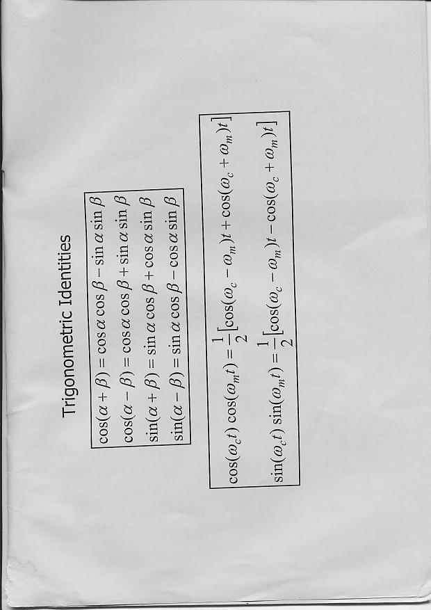
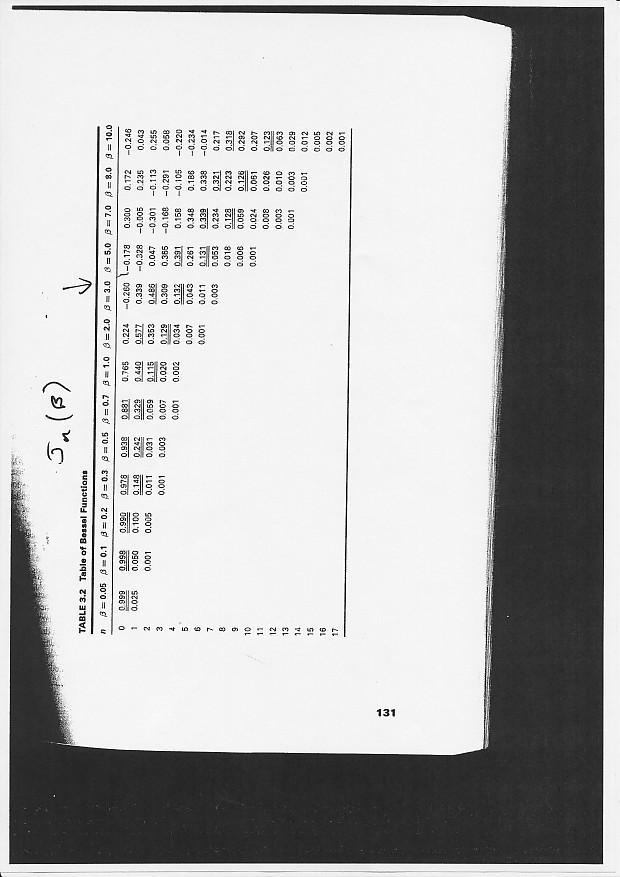
1 TELE3013 Mid-session QUIZ 1 Week 7 10 th April, 2006 Name: Student No: Instrutions to Candidates (1) Time allowed: 90 minutes or so (2) Answer all questions. Total Marks = 90. (3) Marks are as indiated. Questions do NOT have equal marks. (4) All answers are to written in the spae provided in this question paper. (5) This paper may not be retained by the andidate. (6) Trigonometri Identities, Fourier Transform table, and Bessel funtion table are attahed. (7) The paper onsist of 8 questions.
2 Question 1 (5 marks) a) Sketh a blok diagram showing a omplete ommuniation system. Inlude an enoder, modulator, transmitter, and their onverse funtional bloks. (3 marks) b) Explain the purpose of modulation. (2 marks)
3 Question 2 (16 marks) A arrier signal t) A os( ω t) ( = is modulated with a message, m( t) = 3 os + ( ω t) sin( ω t) The message frequeny is f = 100Hz, the arrier frequeny is f = 980kHz, and the arrier amplitude is m A = 20V. a) Express the message in the form m t ) = A ( ω t θ ) ( os m m. [Hint: reall the trigonometri identity, a os ( α ) + bsin( α ) a + b os α tan ( b a) m ( ) m.] (2 marks) b) Hene find the amplitude sensitivity fator, k a, needed to produe an AM s( t) = A 1+ k m( t) os ω t, with a modulation index of signal of the form [ ] ( ) 1 μ = 2. (2 marks) a ) Sketh a blok diagram of an AM modulator. (2 marks)
4 d) Sketh s(t), the modulated signal in the time domain. Show learly the maximum and minimum values of the arrier envelope on your diagram. (2 marks) e) Sketh the magnitude spetra of (i) the arrier, (ii) the message, and (iii) the AM signal. Show all numerial values on your axes that you an. (6 marks) f) What is the modulation effiieny of this AM signal? (2 marks)
5 Question 3 (12 marks) a) Under what onditions an an envelope detetor be used to demodulate an amplitude modulated signal? (2 marks) b) Draw a iruit diagram of an envelope detetor. (3 marks) ) With the aid of graphs, explain the priniples of operation of an envelope detetor. (5 marks) d) An envelope detetor is to be used to reover a message of bandwidth 5 khz from a arrier of frequeny 1 MHz. The resistor used in the RC iruit is to be 100 kω. Choose a suitable value for the apaitor. [Note: There is no unique answer here. Just pik a apaitor value within the range that will get the job done.] (2 marks)
6 Question 4 (14 marks) A message m(t) has the following spetrum; M(f) 2 4 f (khz) It is to be modulated onto a arrier of frequeny 1.2 MHz. a) Write a time domain expression for the DSB-SC signal for this message, in terms of m(t). (1 mark) b) Draw a blok diagram illustrating a simple DSB modulator. (2 marks) ) Sketh the spetrum of the DSB modulated signal. (2 marks) d) What is the bandwidth of the DSB modulated signal? (1 mark)
7 e) Write a time domain expression for the SSB-Upper Sideband modulated signal for this message, in terms of m(t), and the Hilbert transform of the message, m ˆ ( t). (2 marks) f) Draw a blok diagram for an SSB modulator, using the simple phase shift tehnique. (3 marks) g) Sketh the spetrum of the SSB-USB signal for this message. (2 marks) h) What is the bandwidth of the SSB signal for this message? (1 mark)
8 Question 5 (8 marks) a) Under what irumstanes is VSB a more pratial modulation tehnique than SSB? (1 mark) b) Draw a blok diagram of a VSB modulation system. (3 marks) ) A message of bandwidth 10 khz is to be modulated using VSB onto a arrier wave and sent down a hannel that has a bandwidth restrition of 900 khz to 915 khz. (i) Choose an appropriate arrier frequeny. (1 mark) (ii) Sketh a possible transfer funtion for the VSB shaping filter. (3 marks)
9 Question 6 (13 marks) a) Draw a blok diagram for a oherent detetor. (3 marks) b) Derive an expression for the output of the oherent detetor when the input is a DSB modulated signal arrying a message m(t). Denote the frequeny error of the loal osillator Δω and the phase offset θ. (5 marks)
10 ) Draw a blok diagram showing a Phase Loked Loop (PLL). (3 marks) d) Explain briefly why PLLs are so important in oherent detetors. (2 marks)
11 Question 7 (8 marks) a) Draw a blok diagram of a superheterodyne reeiver. (4 marks) b) A superheterodyne reeiver uses an intermediate frequeny of f IF = 455kHz. You wish to tune into a radio station with a arrier frequeny f = 1580 khz. Assuming high-side tuning, what is the frequeny of the loal osillator? (2 marks) ) What is the image frequeny in this ase? (2 marks)
12 Question 8 (14 marks) A single-tone message, m( t) = 2os( 2π 500t), is modulated onto a arrier of frequeny f = 92.9 MHz. The peak frequeny deviation of the modulated wave is Δf = 1kHz. a) What is the modulation index, β? (2 marks) b) Write a time domain expression for the FM modulated wave, assuming a arrier amplitude of 10 Volts. (3 marks) ) Is this Narrowband FM? (1 mark) d) What is the approximate bandwidth of this FM signal? (2 marks) e) Sketh the magnitude spetrum of this FM signal, showing the relative heights of the spetral omponents. (6 marks)
13
14
15
ENSC327 Communications Systems 4. Double Sideband Modulation. Jie Liang School of Engineering Science Simon Fraser University
 ENSC327 Communiations Systems 4. Double Sideband Modulation Jie Liang Shool of Engineering Siene Simon Fraser University 1 Outline DSB: Modulator Spetrum Coherent Demodulator: Three methods Quadrature-arrier
EE140 Introduction to Communication Systems Lecture 7
 3/4/08 EE40 Introdution to Communiation Systems Leture 7 Instrutor: Prof. Xiliang Luo ShanghaiTeh University, Spring 08 Arhiteture of a (Digital) Communiation System Transmitter Soure A/D onverter Soure
ENSC327 Communications Systems 4. Double Sideband Modulation. School of Engineering Science Simon Fraser University
 ENSC327 Communiations Systems 4. Double Sideband Modulation Shool of Engineering Siene Simon Fraser University 1 Outline Required Bakground DSB: Modulator Spetrum Coherent Demodulator: Three methods Quadrature-arrier
6. Amplitude Modulation
 6. Amplitude Modulation Modulation is a proess by whih some parameter of a arrier signal is varied in aordane with a message signal. The message signal is alled a modulating signal. Definitions A bandpass
Introduction to Analog And Digital Communications
 Introdution to Analog And Digital Communiations Seond Edition Simon Haykin, Mihael Moher Chapter 9 Noise in Analog Communiations 9.1 Noise in Communiation Systems 9. Signal-to-Noise Ratios 9.3 Band-Pass
Lecture 4: Amplitude Modulation (Double Sideband Suppressed Carrier, DSB-SC) Dr. Mohammed Hawa
 Dr. Mohammed Hawa") Leture 4: Amplitude Modulation (Double Sideband Suppressed Carrier, DSB-SC) Dr. Mohammed Hawa Eletrial Engineering Department University of Jordan EE421: Communiations I Notation 2 1 Three Modulation Types
Leture 4: Amplitude Modulation (Double Sideband Suppressed Carrier, DSB-SC) Dr. Mohammed Hawa Eletrial Engineering Department University of Jordan EE421: Communiations I Notation 2 1 Three Modulation Types
Dr. Md. Farhad Hossain Associate Professor Department of EEE, BUET
 EEE 309 Communiation Theory Semester: January 06 Dr. Md. Farhad Hossain Assoiate Proessor Department o EEE, BUET Email: marhadhossain@eee.buet.a.bd Oie: ECE 33, ECE Building Part 03-3 Single-sideband Suppressed
Lecture 4: Amplitude Modulation (Double Sideband Suppressed Carrier, DSB-SC) Dr. Mohammed Hawa
 Dr. Mohammed Hawa") Leture 4: Amplitude Modulation (Double Sideband Suppressed Carrier, DSB-SC) Dr. Mohammed Hawa Eletrial Engineering Department University of Jordan EE421: Communiations I Notation 2 1 Three Modulation Types
Leture 4: Amplitude Modulation (Double Sideband Suppressed Carrier, DSB-SC) Dr. Mohammed Hawa Eletrial Engineering Department University of Jordan EE421: Communiations I Notation 2 1 Three Modulation Types
Analog Communications
 1 Analog Communiations Amplitude Modulation (AM) Frequeny Modulation (FM) 2 Radio broadasting 30-300M Hz SOURCE Soure Transmitter Transmitted signal Channel Reeived signal Reeiver User Analog baseband
ELEC 350 Communications Theory and Systems: I. Analog Signal Transmission and Reception. ELEC 350 Fall
 ELEC 350 Communiations Theory and Systems: I Analog Signal Transmission and Reeption ELEC 350 Fall 2007 1 ELEC 350 Fall 2007 2 Analog Modulation A large number o signals are analog speeh musi video These
ANALOG COMMUNICATION (9)
") 11/5/013 DEARTMENT OF ELECTRICAL &ELECTRONICS ENGINEERING ANALOG COMMUNICATION (9) Fall 013 Original slides by Yrd. Doç. Dr. Burak Kellei Modified by Yrd. Doç. Dr. Didem Kivan Tureli OUTLINE Noise in Analog
11/5/013 DEARTMENT OF ELECTRICAL &ELECTRONICS ENGINEERING ANALOG COMMUNICATION (9) Fall 013 Original slides by Yrd. Doç. Dr. Burak Kellei Modified by Yrd. Doç. Dr. Didem Kivan Tureli OUTLINE Noise in Analog
Single Sideband (SSB) AM
 AM") Single Sideband (SSB) AM Leture 7 Why SSB-AM? Spetral eiieny is o great importane. Conventional & DSB-SC oupy twie the message bandwidth. All the inormation is ontained in either hal the other is redundant.
Single Sideband (SSB) AM Leture 7 Why SSB-AM? Spetral eiieny is o great importane. Conventional & DSB-SC oupy twie the message bandwidth. All the inormation is ontained in either hal the other is redundant.
Chapter 3 Amplitude Modulation. Wireless Information Transmission System Lab. Institute of Communications Engineering National Sun Yat-sen University
 Chapter 3 Amplitude Modulation Wireless Information Transmission System Lab. Institute of Communiations Engineering National Sun Yat-sen University Outline 3.1 Introdution 3.2 Amplitude Modulation 3.3
Modulation Technique:
 Modulation Tehnique: There are two basi failies of ontinuous-wave odulation tehniques: 1. Aplitude odulation, in whih the aplitude of a sinusoidal arrier is varied in aordane with an inoing essage signal.
ELG3175 Introduction to Communication Systems. Conventional AM
 ELG317 Introdution to Communiation Systems Conventional AM Disadvantages o DSB-SC The reeiver must generate a replia o the arrier in order to demodulate a DSB-SC signal. Any phase and/or requeny error
AMPLITUDE MODULATION AND DEMODULATION
 Modulation is a tehnique to transit inforation via radio arrier wavefor. It is a non-linear proess that generates additional frequenies, as we will see. Aplitude Modulation (AM) works by varying the aplitude
ANALOG COMMUNICATIONS IV Sem. Prepared by Mr. T. Nagarjuna ECE Department
 ANALOG COMMUNICAIONS IV Sem Prepared by Mr.. Nagaruna ECE Department UNI I SIGNAL ANALYSIS AND LI SYSEMS Classifiation of Signals Deterministi & Non Deterministi Signals Periodi & A periodi Signals Even
EKT358 Communication Systems
 EKT358 Communiation Systems Chapter 2 Amplitude Modulation Topis Covered in Chapter 2 2-1: AM Conepts 2-2: Modulation Index and Perentage of Modulation 2-3: Sidebands and the Frequeny Domain 2-4: Single-Sideband
Communication Systems Lecture 7. Dong In Kim School of Info/Comm Engineering Sungkyunkwan University
 Communiation Systems Leture 7 Dong In Kim Shool o Ino/Comm Engineering Sungkyunkwan University 1 Outline Expression o SSB signals Waveorm o SSB signals Modulators or SSB: Frequeny disrimination Phase disrimination
Module 5 Carrier Modulation. Version 2 ECE IIT, Kharagpur
 Module 5 Carrier Modulation Version ECE II, Kharagpur Lesson 5 Quaternary Phase Shift Keying (QPSK) Modulation Version ECE II, Kharagpur After reading this lesson, you will learn about Quaternary Phase
Figure 4.11: Double conversion FM receiver
 74 4.8 FM Reeivers FM reeivers, like their AM ounterparts, are superheterodyne reeivers. Figure 4.11 shows a simplified blok diagram for a double onversion superheterodyne FM reeiver Figure 4.11: Double
(b) What are the differences between FM and PM? (c) What are the differences between NBFM and WBFM? [9+4+3]
![(b) What are the differences between FM and PM? (c) What are the differences between NBFM and WBFM? [9+4+3]](/thumbs/85/91561193.jpg "(b) What are the differences between FM and PM? (c) What are the differences between NBFM and WBFM? [9+4+3]") Code No: RR220401 Set No. 1 1. (a) The antenna current of an AM Broadcast transmitter is 10A, if modulated to a depth of 50% by an audio sine wave. It increases to 12A as a result of simultaneous modulation
Code No: RR220401 Set No. 1 1. (a) The antenna current of an AM Broadcast transmitter is 10A, if modulated to a depth of 50% by an audio sine wave. It increases to 12A as a result of simultaneous modulation
Code No: R Set No. 1
 Code No: R05220405 Set No. 1 II B.Tech II Semester Regular Examinations, Apr/May 2007 ANALOG COMMUNICATIONS ( Common to Electronics & Communication Engineering and Electronics & Telematics) Time: 3 hours
Amplitude Modulation, II
 Amplitude Modulation, II Single sideband modulation (SSB) Vestigial sideband modulation (VSB) VSB spectrum Modulator and demodulator NTSC TV signsals Quadrature modulation Spectral efficiency Modulator
B.Tech II Year II Semester (R13) Supplementary Examinations May/June 2017 ANALOG COMMUNICATION SYSTEMS (Electronics and Communication Engineering)
 Supplementary Examinations May/June 2017 ANALOG COMMUNICATION SYSTEMS (Electronics and Communication Engineering)") Code: 13A04404 R13 B.Tech II Year II Semester (R13) Supplementary Examinations May/June 2017 ANALOG COMMUNICATION SYSTEMS (Electronics and Communication Engineering) Time: 3 hours Max. Marks: 70 PART A
Code: 13A04404 R13 B.Tech II Year II Semester (R13) Supplementary Examinations May/June 2017 ANALOG COMMUNICATION SYSTEMS (Electronics and Communication Engineering) Time: 3 hours Max. Marks: 70 PART A
Introductory Notions
 Introdutory Notions - he blok diagram of a transmission link, whih onveys information by means of eletromagneti signals, is depited in the figure below. Message Signal aqusition blok Information ransmitter
Digitally Demodulating Binary Phase Shift Keyed Data Signals
 Digitally Demodulating Binary Phase Shift Keyed Signals Cornelis J. Kikkert, Craig Blakburn Eletrial and Computer Engineering James Cook University Townsville, Qld, Australia, 4811. E-mail: Keith.Kikkert@ju.edu.au,
Principles of Communications
 Priniples of Communiations Meixia Tao Dept. of Eletroni Engineering Shanghai Jiao Tong University Chapter 3: Analog Modulation Seleted from Ch 3, Ch 4.-4.4, Ch 6.-6. of of Fundamentals of Communiations
Problems from the 3 rd edition
 (2.1-1) Find the energies of the signals: a) sin t, 0 t π b) sin t, 0 t π c) 2 sin t, 0 t π d) sin (t-2π), 2π t 4π Problems from the 3 rd edition Comment on the effect on energy of sign change, time shifting
BPSK so that we have a discrete set of RF signals. t)cos(
cos(") BPSK. BPSK Introdution Reall that the most general modulation has the form s( t) a( t)os[ t ( t)]. We remared earlier that phase modulation was not an effetive way to implement analog ommuniation, one
BPSK. BPSK Introdution Reall that the most general modulation has the form s( t) a( t)os[ t ( t)]. We remared earlier that phase modulation was not an effetive way to implement analog ommuniation, one
Outline. Communications Engineering 1
 Outline Introduction Signal, random variable, random process and spectra Analog modulation Analog to digital conversion Digital transmission through baseband channels Signal space representation Optimal
EE (082) Chapter IV: Angle Modulation Lecture 21 Dr. Wajih Abu-Al-Saud
 Chapter IV: Angle Modulation Lecture 21 Dr. Wajih Abu-Al-Saud") EE 70- (08) Chapter IV: Angle Modulation Leture Dr. Wajih Abu-Al-Saud Effet of Non Linearity on AM and FM signals Sometimes, the modulated signal after transmission gets distorted due to non linearities
EE 70- (08) Chapter IV: Angle Modulation Leture Dr. Wajih Abu-Al-Saud Effet of Non Linearity on AM and FM signals Sometimes, the modulated signal after transmission gets distorted due to non linearities
Angle Modulated Systems
 Angle Modulated Systems Angle of carrier signal is changed in accordance with instantaneous amplitude of modulating signal. Two types Frequency Modulation (FM) Phase Modulation (PM) Use Commercial radio
Fatih University Electrical and Electronics Engineering Department EEE Communications I EXPERIMENT 4 AM DEMODULATORS
 Fatih University Eletrial and Eletronis Engineering Departent EEE 316 - Couniations I EXPERIMENT 4 AM DEMODULATORS 4.1 OBJECTIVES 1. Understanding the priniple of aplitude odulation and deodulation.. Ipleenting
Objectives. Presentation Outline. Digital Modulation Lecture 04
 Digital Modulation Leture 04 Filters Digital Modulation Tehniques Rihard Harris Objetives To be able to disuss the purpose of filtering and determine the properties of well known filters. You will be able
4- Single Side Band (SSB)
") 4- Single Side Band (SSB) It can be shown that: s(t) S.S.B = m(t) cos ω c t ± m h (t) sin ω c t -: USB ; +: LSB m(t) X m(t) cos ω c t -π/ cos ω c t -π/ + s S.S.B m h (t) X m h (t) ± sin ω c t 1 Tone Modulation:
4- Single Side Band (SSB) It can be shown that: s(t) S.S.B = m(t) cos ω c t ± m h (t) sin ω c t -: USB ; +: LSB m(t) X m(t) cos ω c t -π/ cos ω c t -π/ + s S.S.B m h (t) X m h (t) ± sin ω c t 1 Tone Modulation:
Generating 4-Level and Multitone FSK Using a Quadrature Modulator
 Generating 4-Level and Multitone FSK Using a Quadrature Modulator Page 1 of 9 Generating 4-Level and Multitone FSK Using a Quadrature Modulator by In a reent olumn (lik on the Arhives botton at the top
Speech, music, images, and video are examples of analog signals. Each of these signals is characterized by its bandwidth, dynamic range, and the
 Speech, music, images, and video are examples of analog signals. Each of these signals is characterized by its bandwidth, dynamic range, and the nature of the signal. For instance, in the case of audio
Amplitude Modulated Systems
 Amplitude Modulated Systems Communication is process of establishing connection between two points for information exchange. Channel refers to medium through which message travels e.g. wires, links, or
2. Continuous-wave modulation
 . Continuous-wave odulation 1. Appliation goal We study representations in tie and frequeny doain for two types of ontinuous wave odulation: aplitude odulation (AM) and frequeny odulation (FM).. Continuous-wave
 Modulations Analog Modulations Amplitude modulation (AM) Linear modulation Frequency modulation (FM) Phase modulation (PM) cos Angle modulation FM PM Digital Modulations ASK FSK PSK MSK MFSK QAM PAM Etc.
A 24 GHz Band FM-CW Radar System for Detecting Closed Multiple Targets with Small Displacement
 A 24 GHz Band FM-CW Radar System for Deteting Closed Multiple Targets with Small Displaement Kazuhiro Yamaguhi, Mitsumasa Saito, Takuya Akiyama, Tomohiro Kobayashi and Hideaki Matsue Tokyo University of
Angle Modulation Frequency Modulation
 Angle Modulation Frequeny Modulation Consider again the general arrier v t =V osω t + φ ωt + φ represents the angle o the arrier. There are two ways o varying the angle o the arrier. a) By varying the
Analog Communication (10EC53) Unit 3 Quadrature Carrier Multiplexing
 Unit 3 Quadrature Carrier Multiplexing") Analog Couniation (0EC53) Unit 3 Quadrature Carrier Multiplexing A Quadrature Carrier Multiplexing (QCM) or Quadrature Aplitude Modulation (QAM) ethod enables two DSBSC odulated waves, resulting ro two
Analog Couniation (0EC53) Unit 3 Quadrature Carrier Multiplexing A Quadrature Carrier Multiplexing (QCM) or Quadrature Aplitude Modulation (QAM) ethod enables two DSBSC odulated waves, resulting ro two
Chapter 3: Analog Modulation Cengage Learning Engineering. All Rights Reserved.
 Contemporary Communication Systems using MATLAB Chapter 3: Analog Modulation 2013 Cengage Learning Engineering. All Rights Reserved. 3.1 Preview In this chapter we study analog modulation & demodulation,
AM Limitations. Amplitude Modulation II. DSB-SC Modulation. AM Modifications
 Lecture 6: Amplitude Modulation II EE 3770: Communication Systems AM Limitations AM Limitations DSB-SC Modulation SSB Modulation VSB Modulation Lecture 6 Amplitude Modulation II Amplitude modulation is
Amplitude Modulation II
 Lecture 6: Amplitude Modulation II EE 3770: Communication Systems Lecture 6 Amplitude Modulation II AM Limitations DSB-SC Modulation SSB Modulation VSB Modulation Multiplexing Mojtaba Vaezi 6-1 Contents
Communication Systems, 5e
 Communiation Systems, 5e Chapter 7: Analog Communiation Systems A. Brue Carlson Paul B. Crilly 010 The Mraw-Hill Companies Chapter 7: Analog Communiation Systems Reeiver blok diagram design Image requeny
3.1 Introduction to Modulation
 Haberlesme Sistemlerine Giris (ELE 361) 9 Eylul 2017 TOBB Ekonomi ve Teknoloji Universitesi, Guz 2017-18 Dr. A. Melda Yuksel Turgut & Tolga Girici Lecture Notes Chapter 3 Amplitude Modulation Speech, music,
Fatih University Electrical and Electronics Engineering Department EEE Communications I EXPERIMENT 5 FM MODULATORS
 Fatih University Eletrial and Eletronis Engineering epartent EEE 36 - Couniations I EXPERIMENT 5 FM MOULATORS 5. OBJECTIVES. Studying the operation and harateristis of a varator diode.. Understanding the
CHAPTER 2. AMPLITUDE MODULATION (AM) 2.3 AM Single Side Band Communications
 2.3 AM Single Side Band Communications") CHAPTER AMPLITUDE MODULATION (AM).3 AM Single Side Band Couniations OBJECTIVES To define and desribe AM single sideband To opare single sideband transission to onventional double sideband AM The explain
CHAPTER AMPLITUDE MODULATION (AM).3 AM Single Side Band Couniations OBJECTIVES To define and desribe AM single sideband To opare single sideband transission to onventional double sideband AM The explain
Multiplication/Modulation Property For Continuous-Time.
 Multipliation/Modulation Property For Continuous-Time. X( X(j) y(=(.( Y(j)=[C(j) X(j)]/2π )] ( )* ( [ 2 ) ( ). (. π j X j C t t T F X ( C(j) + = = = θ θ θ θ θ π d Xj j C jw Y ) ( ) ( 2 ) ( Multipliation/Modulation
Parameters of the radio channels that affect digital signal transmissions Propagation Environment Attenuation Index, γ
 Parameters of the radio hannels that affet digital signal transmissions 1.Free spae attenuation - the signal undergoes an average attenuation that depends on the length of the path and signal s frequeny
Lecture 6. Angle Modulation and Demodulation
 Lecture 6 and Demodulation Agenda Introduction to and Demodulation Frequency and Phase Modulation Angle Demodulation FM Applications Introduction The other two parameters (frequency and phase) of the carrier
Lecture Notes On Analogue Communication Techniques(Module 1 & 2) Topics Covered: 1. Spectral Analysis of Signals 2. Amplitude Modulation Techniques
 Topics Covered: 1. Spectral Analysis of Signals 2. Amplitude Modulation Techniques") Leture Notes On Analogue Communiation Tehniques(Module 1 & ) Topis Covered: 1. Spetral Analysis of Signals. Amplitude Modulation Tehniques 3. Angle Modulation 4. Mathematial Representation of Noise 5.
Leture Notes On Analogue Communiation Tehniques(Module 1 & ) Topis Covered: 1. Spetral Analysis of Signals. Amplitude Modulation Tehniques 3. Angle Modulation 4. Mathematial Representation of Noise 5.
EC2252: COMMUNICATION THEORY SEM / YEAR: II year DEPARTMENT OF ELECTRONICS AND COMMUNICATION ENGINEERING
 EC2252: COMMUNICATION THEORY SEM / YEAR: II year DEPARTMENT OF ELECTRONICS AND COMMUNICATION ENGINEERING QUESTION BANK SUBJECT CODE : EC2252 SEM / YEAR : II year SUBJECT NAME : COMMUNICATION THEORY UNIT
THE STATE UNIVERSITY OF NEW JERSEY RUTGERS. College of Engineering Department of Electrical and Computer Engineering
 THE STATE UNIVERSITY OF NEW JERSEY RUTGERS College of Engineering Department of Electrical and Computer Engineering 332:322 Principles of Communications Systems Spring Problem Set 3 1. Discovered Angle
Twelve voice signals, each band-limited to 3 khz, are frequency -multiplexed using 1 khz guard bands between channels and between the main carrier
 Twelve voice signals, each band-limited to 3 khz, are frequency -multiplexed using 1 khz guard bands between channels and between the main carrier and the first channel. The modulation of the main carrier
Master Degree in Electronic Engineering
 Master Degree in Electronic Engineering Analog and telecommunication electronic course (ATLCE-01NWM) Miniproject: Baseband signal transmission techniques Name: LI. XINRUI E-mail: s219989@studenti.polito.it
VALLIAMMAI ENGINEERING COLLEGE
 VALLIAMMAI ENGINEERING COLLEGE SRM Nagar, Kattankulathur 603 203. DEPARTMENT OF ELECTRONICS & COMMUNICATION ENGINEERING QUESTION BANK SUBJECT : EC6402 COMMUNICATION THEORY SEM / YEAR: IV / II year B.E.
Calculation of the maximum power density (averaged over 4 khz) of an angle modulated carrier
 of an angle modulated carrier") Re. ITU-R SF.675-3 1 RECOMMENDATION ITU-R SF.675-3 * CALCULATION OF THE MAXIMUM POWER DENSITY (AVERAGED OVER 4 khz) OF AN ANGLE-MODULATED CARRIER Re. ITU-R SF.675-3 (199-1992-1993-1994) The ITU Radioommuniation
Re. ITU-R SF.675-3 1 RECOMMENDATION ITU-R SF.675-3 * CALCULATION OF THE MAXIMUM POWER DENSITY (AVERAGED OVER 4 khz) OF AN ANGLE-MODULATED CARRIER Re. ITU-R SF.675-3 (199-1992-1993-1994) The ITU Radioommuniation
ELEC 350 Communications Theory and Systems: I. Review. ELEC 350 Fall
 ELEC 350 Communications Theory and Systems: I Review ELEC 350 Fall 007 1 Final Examination Saturday, December 15-3 hours Two pages of notes allowed Calculator Tables provided Fourier transforms Table.1
Elements of Communication System Channel Fig: 1: Block Diagram of Communication System Terminology in Communication System
 Content:- Fundamentals of Communication Engineering : Elements of a Communication System, Need of modulation, electromagnetic spectrum and typical applications, Unit V (Communication terminologies in communication
Analog Communication.
 Analog Communication Vishnu N V Tele is Greek for at a distance, and Communicare is latin for to make common. Telecommunication is the process of long distance communications. Early telecommunications
Reasons for Choosing Encoding Techniques. Signal Encoding Techniques. Reasons for Choosing Encoding Techniques. Signal Encoding Criteria
 Reaon for Chooing Enoding Tehnique Signal Enoding Tehnique Chapter 6 Digital data, digital ignal Equipment le omplex and expenive than digital-to-analog modulation equipment Analog data, digital ignal
EE470 Electronic Communication Theory Exam II
 EE470 Electronic Communication Theory Exam II Open text, closed notes. For partial credit, you must show all formulas in symbolic form and you must work neatly!!! Date: November 6, 2013 Name: 1. [16%]
1B Paper 6: Communications Handout 2: Analogue Modulation
 1B Paper 6: Communications Handout : Analogue Modulation Ramji Venkataramanan Signal Processing and Communications Lab Department of Engineering ramji.v@eng.cam.ac.uk Lent Term 16 1 / 3 Modulation Modulation
Plastic SO-16 Package. Pin Configuration 16 V CC L. 15 RF out 14 GROUND 13 GROUND. 12 I ref. 11 I mod 10 GROUND 9 DO NOT CONNECT
 Silicon Bipolar RFI 9 MHz Vector Modulator Technical Data HPMX-3 Features 1 MHz Output Frequency Range + dbm Peak P out Unbalanced Ω Output Internal 9 Phase Shifter Volt, 3 ma Bias SO-1 Surface Mount Package
Solutions to some sampled questions of previous finals
 Solutions to some sampled questions of previous finals First exam: Problem : he modulating signal m(a m coπf m is used to generate the VSB signal β cos[ π ( f c + f m ) t] + (1 β ) cos[ π ( f c f m ) t]
Linear analysis limitations
 RF power amplifier he final stage (output stage) allows delivering power needed by devies suh as speakers, antennas, et he output signal shows high dynami both in voltage and in urrent, so overing a great
Amplitude Modulation Chapter 2. Modulation process
 Question 1 Modulation process Modulation is the process of translation the baseband message signal to bandpass (modulated carrier) signal at frequencies that are very high compared to the baseband frequencies.
Abstract. 1. Introduction. 2. Fading
 An Interative Simulation for Flat Fading P.Marihamy*, J.Senthilkumar and V.Vijayarangan ECE Dept., National Engineering College Kovilpatti -68 503, India. * Nizwa College of Tehnology, Sultanate of Oman
Version of 7. , using 30 points from 5 rad/s to 5 krad/s. Paste your plot below. Remember to label your plot.
 Version 1.2 1 of 7 Your Name Passive and Ative Filters Date ompleted PELAB MATLAB = 1000 s + 1000, using 30 points from 5 rad/s to 5 krad/s. Paste your plot below. emember to label your plot. 1. reate
Introduction & Amplitude Modulation
 Departent of Eletronis and Couniation Engineering, KUET Introdution & Aplitude Modulation Dr. Monir Hossen ECE, KUET Departent of Eletronis and Couniation Engineering, KUET Introdution (1/) Long distane
Research on Blanket Jamming to Beidou Navigation Signals Based on BOC Modulation
 Int. J. Communiations, Network and System Sienes, 6, 9, 35-44 Published Online May 6 in SiRes. http://www.sirp.org/ournal/ins http://dx.doi.org/.436/ins.6.95 Researh on Blanket Jamming to Beidou Navigation
ELE636 Communication Systems
 ELE636 Communication Systems Chapter 5 : Angle (Exponential) Modulation 1 Phase-locked Loop (PLL) The PLL can be used to track the phase and the frequency of the carrier component of an incoming signal.
Charan Langton, Editor
 Charan Langton, Editor SIGNAL PROCESSING & SIMULATION NEWSLETTER Baseband, Passband Signals and Amplitude Modulation The most salient feature of information signals is that they are generally low frequency.
DEPARTMENT OF E.C.E.
 PVP SIDDHARTHA INSTITUTE OF TECHNOLOGY, KANURU, VIJAYAWADA-7 DEPARTMENT OF E.C.E. ANALOG COMMUNICATIONS LAB MANUAL Department of Electronics & Communication engineering Prasad V.Potluri Siddhartha Institute
Introduction to Amplitude Modulation
 1 Introduction to Amplitude Modulation Introduction to project management. Problem definition. Design principles and practices. Implementation techniques including circuit design, software design, solid
r v = Q enclosed r r E d r l = $ d% B dt r B d r i through dt Where does the word "laser" come from?
 Where does the word "laser" ome from? A: The name of the physiist who invented it. B: The name of the dog of the physiist who invented it C: "Light Amplifiation by Stimulated mission of Radiation" D: It's
EE4512 Analog and Digital Communications Chapter 6. Chapter 6 Analog Modulation and Demodulation
 Chapter 6 Analog Modulation and Demodulation Chapter 6 Analog Modulation and Demodulation Amplitude Modulation Pages 306-309 309 The analytical signal for double sideband, large carrier amplitude modulation
Amplitude Modulation. Ahmad Bilal
 Amplitude Modulation Ahmad Bilal 5-2 ANALOG AND DIGITAL Analog-to-analog conversion is the representation of analog information by an analog signal. Topics discussed in this section: Amplitude Modulation
EE 464 Band-Pass Sampling Example Fall 2018
 EE 464 Band-Pass Sampling Example Fall 2018 Summary This example demonstrates the use of band-pass sampling. First, a band-pass signal is onstruted as a osine modulated speeh signal. This is a double sideband
Double and single side-band suppressed-carrier optical modulator implemented at 1320 nm using LiNbO 3 crystals and bulk optics.
 Double and single side-band suppressed-arrier optial odulator ipleented at 13 n using LiNbO 3 rystals and bulk optis. Azad Siahakoun 1 and Sergio Granieri Departent of Physis and Applied Optis, Rose-Hulan
Problem Sheet 1 Probability, random processes, and noise
 Problem Sheet 1 Probability, random processes, and noise 1. If F X (x) is the distribution function of a random variable X and x 1 x 2, show that F X (x 1 ) F X (x 2 ). 2. Use the definition of the cumulative
DSP First Lab 05: FM Synthesis for Musical Instruments - Bells and Clarinets
 DSP First Lab 05: FM Synthesis for Musial Instruments - Bells and Clarinets Pre-Lab and Warm-Up: You should read at least the Pre-Lab and Warm-up setions of this lab assignment and go over all exerises
Communication Channels
 Communication Channels wires (PCB trace or conductor on IC) optical fiber (attenuation 4dB/km) broadcast TV (50 kw transmit) voice telephone line (under -9 dbm or 110 µw) walkie-talkie: 500 mw, 467 MHz
CHAPTER 3 BER EVALUATION OF IEEE COMPLIANT WSN
 CHAPTER 3 EVALUATIO OF IEEE 8.5.4 COMPLIAT WS 3. OVERVIEW Appliations of Wireless Sensor etworks (WSs) require long system lifetime, and effiient energy usage ([75], [76], [7]). Moreover, appliations an
 VALLIAMMAI ENGINEERING COLLEGE SRM Nagar, Kattankulathur 603 203. DEPARTMENT OF ELECTRONICS & COMMUNICATION ENGINEERING QUESTION BANK EC6402 COMMUNICATION THEORY III YEAR / VI SEMESTER ACADEMIC YEAR 2015-16(EVEN)
EXAMINATION FOR THE DEGREE OF B.E. Semester 1 June COMMUNICATIONS IV (ELEC ENG 4035)
") EXAMINATION FOR THE DEGREE OF B.E. Semester 1 June 2007 101902 COMMUNICATIONS IV (ELEC ENG 4035) Official Reading Time: Writing Time: Total Duration: 10 mins 120 mins 130 mins Instructions: This is a closed
EXAMINATION FOR THE DEGREE OF B.E. Semester 1 June 2007 101902 COMMUNICATIONS IV (ELEC ENG 4035) Official Reading Time: Writing Time: Total Duration: 10 mins 120 mins 130 mins Instructions: This is a closed
Communications IB Paper 6 Handout 2: Analogue Modulation
 Communications IB Paper 6 Handout 2: Analogue Modulation Jossy Sayir Signal Processing and Communications Lab Department of Engineering University of Cambridge jossy.sayir@eng.cam.ac.uk Lent Term c Jossy
Principles of Communications Lecture 3: Analog Modulation Techniques (1) Chih-Wei Liu 劉志尉 National Chiao Tung University
 Chih-Wei Liu 劉志尉 National Chiao Tung University") Priniples of ouniaions Leure 3: nalog Modulaion Tehniques 1 hih-wei Liu 劉志尉 Naional hiao Tung Universiy wliu@wins.ee.nu.edu.w Oulines Linear Modulaion ngle Modulaion Inerferene Feedbak Deodulaors nalog
Priniples of ouniaions Leure 3: nalog Modulaion Tehniques 1 hih-wei Liu 劉志尉 Naional hiao Tung Universiy wliu@wins.ee.nu.edu.w Oulines Linear Modulaion ngle Modulaion Inerferene Feedbak Deodulaors nalog
Vestigial Sideband Modulation KEEE343 Communication Theory Lecture #11, April 7, Prof. Young-Chai Ko
 Vestigial Sideband Modulation KEEE343 Communication Theory Lecture #11, April 7, 2011 Prof. Young-Chai Ko koyc@korea.ac.kr Summary Vestigial sideband modulation Baseband representation of modulated wave
ECE 359 Spring 2003 Handout # 16 April 15, SNR for ANGLE MODULATION SYSTEMS. v(t) = A c cos(2πf c t + φ(t)) for FM. for PM.
 = A c cos(2πf c t + φ(t)) for FM. for PM.") ECE 359 Spring 23 Handout # 16 April 15, 23 Recall that for angle modulation: where The modulation index: ag replacements SNR for ANGLE MODULATION SYSTEMS v(t) = A c cos(2πf c t + φ(t)) t 2πk f m(t )dt
ECE 359 Spring 23 Handout # 16 April 15, 23 Recall that for angle modulation: where The modulation index: ag replacements SNR for ANGLE MODULATION SYSTEMS v(t) = A c cos(2πf c t + φ(t)) t 2πk f m(t )dt
Design and Performance of a 24 GHz Band FM-CW Radar System and Its Application
 Frequeny Design and Performane of a 24 GHz Band FM-CW Radar System and Its Appliation Kazuhiro Yamaguhi, Mitsumasa Saito, Kohei Miyasaka and Hideaki Matsue Tokyo University of Siene, Suwa CQ-S net In.,
UNIT-I AMPLITUDE MODULATION (2 Marks Questions and Answers)
") UNIT-I AMPLITUDE MODULATION (2 Marks Questions and Answers) 1. Define modulation? Modulation is a process by which some characteristics of high frequency carrier Signal is varied in accordance with the
UNIT-I AMPLITUDE MODULATION (2 Marks Questions and Answers) 1. Define modulation? Modulation is a process by which some characteristics of high frequency carrier Signal is varied in accordance with the
Copyright Blind Selected Mapping Techniques for Space-Time Block Coded Filtered Single-Carrier Signals
 Blind Seleted Mapping Tehniques for Spae-Time Blok Coded Filtered Single-Carrier Signals IEEE VTS AWCS 6 6 August 6 @ Tokyo, Japan Amnart Boonkaay Fumiyuki Adahi Wireless Signal roessing Researh Group
Metrol. Meas. Syst., Vol. XVIII (2011), No. 2, pp METROLOGY AND MEASUREMENT SYSTEMS. Index , ISSN
, No. 2, pp METROLOGY AND MEASUREMENT SYSTEMS. Index , ISSN") METROLOGY AND MEASUREMENT SYSTEMS Index 330930, ISSN 0860-8229 www.metrology.pg.gda.pl DAC TESTING USING MODULATED SIGNALS Pavel Fexa, Josef Vedral, Jakub Svatoš CTU Prague, Faulty of Eletrial Engineering
METROLOGY AND MEASUREMENT SYSTEMS Index 330930, ISSN 0860-8229 www.metrology.pg.gda.pl DAC TESTING USING MODULATED SIGNALS Pavel Fexa, Josef Vedral, Jakub Svatoš CTU Prague, Faulty of Eletrial Engineering
Chapter 5. Amplitude Modulation
 Chapter 5 Amplitude Modulation So far we have developed basic signal and system representation techniques which we will now apply to the analysis of various analog communication systems. In particular,
and division (stretch).
.") Filterg AC signals Topi areas Eletrial and eletroni engeerg: AC Theory. Resistane, reatane and impedane. Potential divider an AC iruit. Low pass and high pass filters. Mathematis: etor addition. Trigonometry.
Filterg AC signals Topi areas Eletrial and eletroni engeerg: AC Theory. Resistane, reatane and impedane. Potential divider an AC iruit. Low pass and high pass filters. Mathematis: etor addition. Trigonometry.