ANALOG COMMUNICATIONS IV Sem. Prepared by Mr. T. Nagarjuna ECE Department
|
|
|
- Daniel Jordan
- 5 years ago
- Views:
Transcription
1 ANALOG COMMUNICAIONS IV Sem Prepared by Mr.. Nagaruna ECE Department
2 UNI I SIGNAL ANALYSIS AND LI SYSEMS
3 Classifiation of Signals Deterministi & Non Deterministi Signals Periodi & A periodi Signals Even & Odd Signals Energy & Power Signals
4 Deterministi & Non Deterministi Signals Deterministi signals Behavior of these signals is preditable w.r.t time. here is no unertainty with respet to its value at any time. hese signals an be expressed mathematially. For example xt = sin3t is deterministi signal. Non Deterministi or Random signals Behavior of these signals is random i.e. not preditable w.r.t time. here is an unertainty with respet to its value at any time. hese signals an t be expressed mathematially. For example hermal Noise generated is non deterministi signal.
5 Periodi and Non-periodi Signals Given xt is a ontinuous-time signal x t is periodi if xt = xt+ₒ for any and any integer n Example xt = A oswt xt+ₒ = A os[w t+ₒ+ = A oswt+wₒ= Aoswt+2 = A oswt For non-periodi signals xt xt+ₒ A non-periodi signal is assumed to have a period = Example of non periodi signal is an exponential signal
6 Even and Odd Signals A signal xt is said to be, Even if, xt=x t Odd if, xt= x t xt= x t
7
8 Signal Energy and Power

9 Fourier transform of Standard Signals
10 Systems
11 LI System
12
13 Convolution
14
15 Correlation of signals
16

17 Relation between Convolution and orrelation
18 UNI-II AMPLIUDE AND DOUBLE SIDE BAND SUPPRESSED CARRIER MODULAION Introdution to ommuniation system, need for modulation, frequeny division multiplexing; Amplitude modulation, definition; ime domain and frequeny domain desription, single tone modulation, power relations in amplitude modulation waves; Generation of amplitude modulation wave using,square law and swithing modulators; Detetion of amplitude modulation waves using square law and envelope detetors; Double side band modulation: Double side band suppressed arrier time domain and frequeny domain desription; Generation of double side band suppressed arrier waves using balaned and ring modulators; Coherent detetion of double side band suppressed arrier modulated waves; Costas loop; Noise in amplitude modulation, noise in double side band suppressed arrier.

19 Basi analog ommuniations system Baseband signal eletrial signal Input transduer ransmitter Modulator EM waves modulated signal ransmission Channel Carrier Output transduer Baseband signal eletrial signal Reeiver Demodulator EM waves modulated signal
20 ypes of Analog Modulation Amplitude Modulation AM Amplitude modulation is the proess of varying the amplitude of a arrier wave in proportion to the amplitude of a baseband signal. he frequeny of the arrier remains onstant Frequeny Modulation FM Frequeny modulation is the proess of varying the frequeny of a arrier wave in proportion to the amplitude of a baseband signal. he amplitude of the arrier remains onstant Phase Modulation PM Another form of analog modulation tehnique whih we will not disuss
21 Amplitude Modulation Carrier wave Baseband signal Modulated wave Amplitude varyingfrequeny onstant
22 Advantages of Modulation Redution of antenna size No signal mixing Inreased ommuniation range Multiplexing of signals Possibility of bandwidth adustments Improved reeption quality
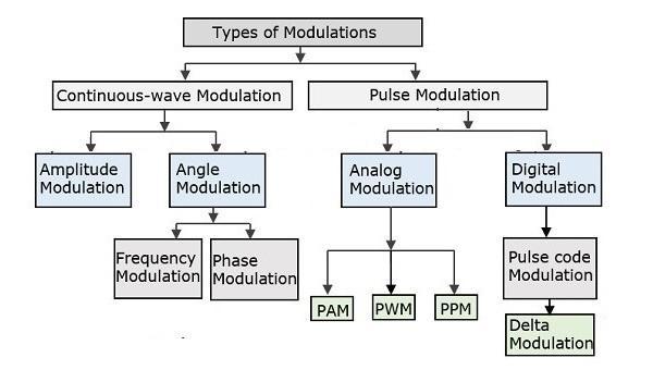
23 ypes of Modulation
24 AM Modulation/Demodulation Soure Channel Sink Modulator Demodulator Baseband Signal with frequeny fm Modulating Signal Bandpass Signal with frequeny f Modulated Signal f >> fm Voie: Hz GSM Cell phone: 900/1800MHz Original Signal with frequeny fm CSULB May 22,
25 Amplitude Modulation he amplitude of high-arrier signal is varied aording to the instantaneous amplitude of the modulating message signal mt. o s 2 f t o s t C a rrie r S ig n a l: o r m t : o s 2 f t o s t M o d u la tin g M e ssag e S ig n a l: o r m m h e A M S ig n a l: s t [ A m t ] o s 2 f t A M CSULB May 22,
26 * AM Signal Math Expression * Mathematial expression for AM: time domain S t 1 k o s t o s t A M m expanding this produes: S t o s t k o s t o s t A M using : os A os B 1 2 os A B os A B m S t o s t o s t o s t k k A M 2 m 2 m In the frequeny domain this gives: Carrier, A=1. Amplitude k/2 k/2 frequeny lower sideband f-fm f f+fm upper sideband CSULB May 22,
27 AM Modulators Square Law Modulator
28 Swithing Modulator
29 Envelope Detetor
30 Square Law Demodulator
31 DSBSC Modulation
32 Balaned Modulator
33 Ring Modulator
34 Coherent Detetor
35 COSAS LOOP
36
37
38 SSBSC Modulation
39 UNI-III SSB-SC AND VSB
40 Frequeny Disrimination Method
41 Phase Disrimination Method
42 Coherent Detetor
43 Consider the following SSBSC wave having a lower sideband. st=a m A /2 os*2πf f m t] he output of the loal osillator is t=a os2πf t From the figure, we an write the output of produt modulator as vt=stt Substitute st and t values in the above equation. vt=a m A /2 os[2πf f m t]a os2πf t =A m A 2 /2 os[2πf f m t]os2πf t =A m A 2 /4 {os[2π2f f m t]+os2πf m t} =A m A 2 /4 {os[2π2f f m t]+os2πf m t} vt=a m A 2 /4 os2πf m t+a m A 2 / 4 os[2π2f f m t] vt=a m A 2 /4 os2πf m t+a m A 2 / 4 os[2π2f f m t] In the above equation, the first term is the saled version of the message signal. It an be extrated by passing the above signal through a low pass filter.
44 herefore, the output of low pass filter is v 0 t=a m A 2 /4 os2πf m t v 0 t=a m A 2 /4 os2πf m t Here, the saling fator is A 2 /4.

45 VSBSC MODULAION
46 Bandwidth of VSBSC Modulation i.e., Bandwidth of VSBSC Modulated Wave = f m + f v Advantages: he following are the advantages of VSBSC modulation. Highly effiient. Redution in bandwidth when ompared to AM and DSBSC waves. Filter design is easy, sine high auray is not needed. he transmission of low frequeny omponents is possible, without any diffiulty. Possesses good phase harateristis. Disadvantages: Following are the disadvantages of VSBSC modulation. Bandwidth is more when ompared to SSBSC wave. Demodulation is omplex. Appliations: he most prominent and standard appliation of VSBSC is for the transmission of television signals. Also, this is the most onvenient and effiient tehnique when bandwidth usage is onsidered.
47 Generation of VSBSC
48 he output of the produt modulator is pt=a os2πf tmt Apply Fourier transform on both sides Pf=A /2 *Mf f +Mf+f ] he above equation represents the equation of DSBSC frequeny spetrum. Let the transfer funtion of the sideband shaping filter be Hf. his filter has the input pt and the output is VSBSC modulated wave st. he Fourier transforms of ptand st are Pf and Sf respetively. Mathematially, we an write Sfas Sf=PfHf Substitute Pf value in the above equation. Sf=A /2 *Mf f +Mf+f ]Hf he above equation represents the equation of VSBSC frequeny spetrum.
49 Demodulation of VSBSC
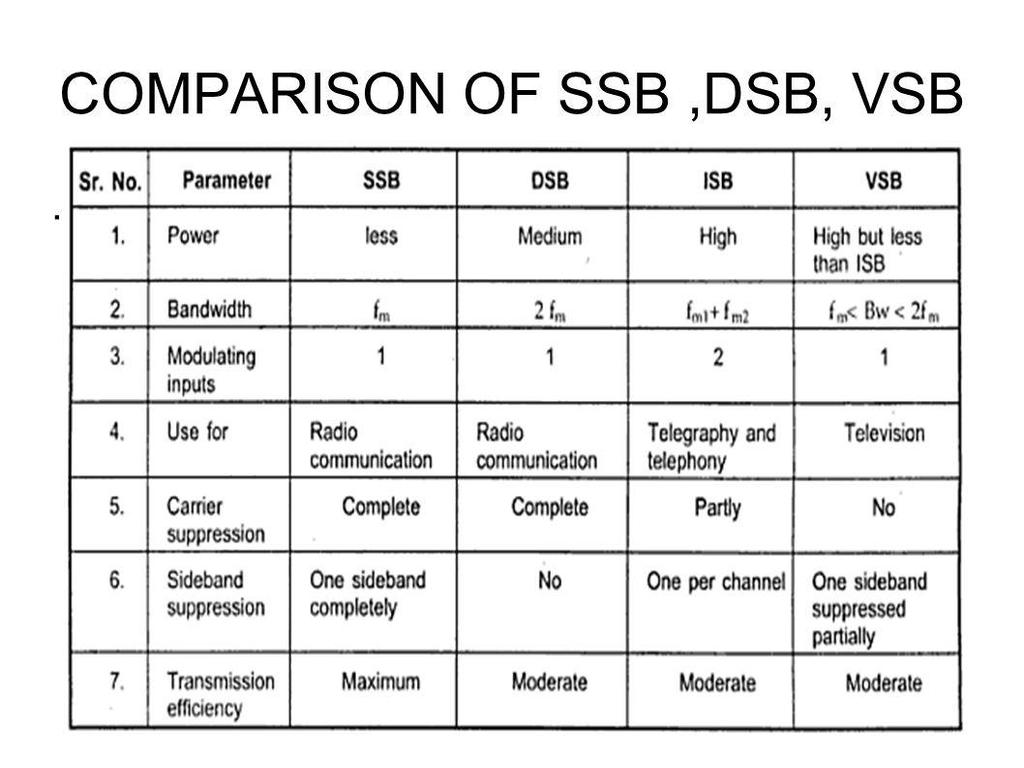
50 Comparison of AM
51
52 Unit-4 Angle Modulation Basi onepts, frequeny modulation: Single tone frequeny modulation, spetrum analysis of sinusoidal frequeny modulation wave, narrow band frequeny modulation, wide band frequeny modulation, transmission bandwidth of frequeny modulation wave, phase modulation, omparison of frequeny modulation and phase modulation; Generation of frequeny modulation waves, diret frequeny modulation and indiret frequeny modulation, detetion of frequeny modulation waves: Balaned frequeny disriminator, Foster Seeley disriminator, ratio detetor, zero rossing detetor, phase loked loop, omparison of frequeny modulation and amplitude modulation; Noise in angle modulation system, threshold effet in angle modulation system, pre-emphasis and de-emphasis.

53 Phase Modulation PM phase modulation signal s t A o s 2 f t k m t p t k m t, k : p h ase sen sitiv ity p p in stan tan o u s freq u en y f t f i k p 2 d m t dt


54 Frequeny Modulation FM frequeny modulation signal s t A o s 2 f t 2 k m d f 0 k f : fre q u e n y s e n s itiv ity in s ta n ta n o u s fre q u e n y f t f k m t i f t a n g le t 2 f d i t 0 i Assume zero initial phase 2 f t 2 k m d f t 0


55 FM Charateristis Charateristis of FM signals Zero-rossings are not regular Envelope is onstant FM and PM signals are similar
56 Relations between FM and PM F M o f m t P M o f m d t 0 P M o f m t F M o f d m t dt
57 FM/PM Example ime/frequeny
58 Frequeny Modulation FM frequeny modulation signal s t A o s 2 f t 2 k m d f 0 k f : fre q u e n y s e n s itiv ity in s ta n ta n o u s fre q u e n y f t f k m t i f t a n g le t 2 f d i t 0 i Assume zero initial phase 2 f t 2 k m d f t 0 m t A o s 2 f t f f k A o s 2 f t m m i f m m f i d 2 k A o s 2 f d f m m d d f t d t 2 d t 2 d t t 1 f 2 k A f m o s 2 f m 2 L e t t
59 Frequeny deviation Δf Frequeny Deviation differene between the maximum instantaneous and arrier frequeny Definition: f k A k m a x m t f m f Relationship with instantaneous frequeny sin g le-to n e m t ase: f f f o s2 f t i m g en eral ase: f f f f f i Question: Is bandwidth of st ust 2Δf? No, instantaneous frequeny is not equivalent to spetrum frequeny with non-zero power! St has spetrum frequeny with non-zero power.
60 Modulation Index Indiate by how muh the modulated variable instantaneous frequeny varies around its unmodulated level message frequeny m a x k m t a A M e n v e lo p e :, 1 F M fre q u e n y: A m a x k m t f f m t Bandwidth a t m d t Re t A os w t k f a t sin w t k 2 f 2! a 2 t os w t k 2 f 3! a 3 t sin w t...

61 Narrow Band Angle Modulation Definition k f a t 1 Equation t A os w t k f m t sin w t Comparison with AM Only phase differene of Pi/2 Frequeny: similar ime: AM: frequeny onstant FM: amplitude onstant Conlusion: NBFM signal is similar to AM signal NBFM has also bandwidth 2W. twie message signal bandwidth
62 Example
63 Blok diagram of a method for generating a narrowband FM signal.
64 Wideband FM signal Wide Band FM m t A o s 2 f t Fourier series representation m s t A o s 2 f t sin 2 f t m m s t A J o s 2 f n f t n m n A S f J f f n f f f n f n m m 2 n J n : n-th o rd e r B e ssel fu n tio n o f th e firs t k in d
65 Example

66 Bessel Funtion of First Kind If is s m a ll, th e n 1,, 2 0 fo r a ll n n n n n n J J J J J n J
67 Spetrum of WBFM Chapter 5.2 Spetrum when mt is single-tone s t A o s 2 f t sin 2 f t A J o s 2 f n f t m n m n A S f Example 2.2 J f f n f f f n f n m m 2 n
68 Spetrum Properties 1. freq u en ies: f, f f, f 2 f,, f n f, m m m fo r all n. h eo retially in fin i te b an d w id th. 2. F o r << 1 N B F M, freq u en y: f, f f m J 1, J J, J 0 fo r all n n A 3. M ag n itu d e o f f n f : J, d ep en d o n m n 2 4. C a rrie r f m a g n itu d e J a n b e 0 fo r so m e A v e ra g e p o w e r: P A J A 2 2 n n
69 Bandwidth of FM Fats FM has side frequenies extending to infinite frequeny theoretially infinite bandwidth But side frequenies beome negligibly small beyond a point pratially finite bandwidth FM signal bandwidth equals the required transmission hannel bandwidth Bandwidth of FM signal is approximately by Carson s Rule whih gives lower-bound
70 Carson s Rule Nearly all power lies within a bandwidth of For single-tone message signal with frequeny f m B 2 f 2 f 2 1 f m m For general message signal mt with bandwidth or highest frequeny W B 2 f 2W 2 D 1 W w h e re D f is d e v ia tio n ra tio e q u iv a le n t to, W f m ax k m t f
71 ECE 4371 Fall 2008

72 ECE 4371 Fall 2008
73 ECE 4371 Fall 2008
74 ECE 4371 Fall 2008
75 ECE 4371 Fall 2008
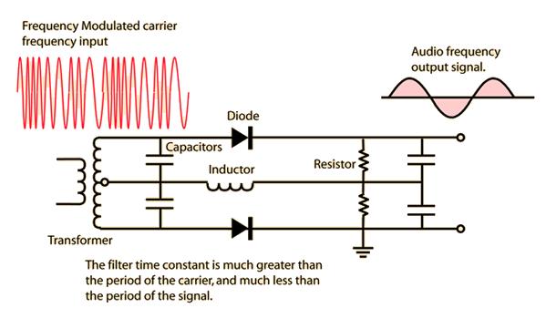
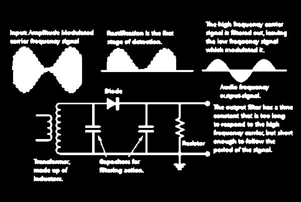
76 FM demodulation

77
78
79
80
81
82
83
84
85
86

87 Frequeny Response
88 Unit-V Reeivers and Sampling heorem
89
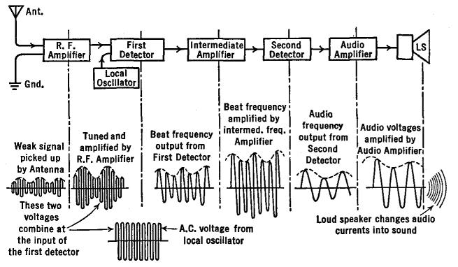
90 Super heterodyne Reeiver
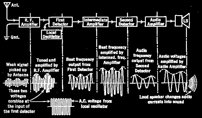
91 FM superheterodyne Rx
92 AGC
93 Sampling heorem
94 Continuous to Disrete-ime Signal Converter x t C/D xn= x n Sampling rate
95 C/D System x t st x s t Conversion from impulse train to disrete-time sequene xn= x n
96 Sampling with Periodi Impulse train x t x t t t xn xn n n

97 Sampling with Periodi Impulse train We want to restore x t from xn. What ondition has to be plaed on the sampling rate? x t x t t t xn xn n n
98 C/D System x t st x s t Conversion from impulse train to disrete-time sequene xn= x n n s t t n n x s t x t s t n x t t n n n n x n t n
99 C/D System X s 1 X * S Conversion from 2 x s t impulse train to disrete-time sequene s s x t st S 2 k, 2 k xn= x n n s t t n n x s t x t s t n x t t n n n n x n t n
100 C/D System * 2 1 S X X s k S s k s 2, 2 s : Sampling Frequeny k s s k X X 2 * 2 1
101 C/D System k s s k X X 2 * 2 1 k s k X * 1 k s k X 1 k s s k X X 1
102 Band-Limited Signals Band-Limited 1 X N N Band-Unlimited Y
103 X 1 k k Sampling s of Band-Limited ssignals s X, 2 Band-Limited 1 X 3 s Sampling with Higher Frequeny 2 s N 2/ N S s s 2 s 3 s Sampling with Lower Frequeny 2/ S 6 s 4 s 2 s 2 s 4 s 6 s

104 X s 1 X k Reoverability k s, s 2 Band-Limited 1 X 3 s Sampling with Higher Frequeny 2 s N 2/ N S s > 2 N s s 2 s 3 s Sampling with Lower Frequeny 2/ S s < 2 N 6 s 4 s 2 s 2 s 4 s 6 s
105 X 1 k scase 1: s > 2 k N X s, s 2 N 1 X N 2/ S 3 s 3 s 2 s 2 s s s 2 s 3 s 1/ X s s s 2 s 3 s


106 X 1 k scase 1: s > 2 k N X s, s 2 Passing X s through a lowpass filter with utoff frequeny N < < s N, the original signal an be reovered. N 1 2/ X N S X s is a periodi funtion with period s. 3 s 3 s 2 s 2 s s s 2 s 3 s 1/ X s s s 2 s 3 s
107 X s 1 k X k s, s 2 Case 2: s < 2 N 1 X N N 2/ S 6 s 4 s 2 s 2 s 4 s 6 s 1/ X s 6 s 4 s 2 s 2 s 4 s 6 s


108 X s 1 k X k s, s 2 Case 2: s < 2 N No way to reover the original signal. N 1 2/ X N S X s is a periodi funtion with period s. 6 s 4 s 2 s 2 s 4 s 6 s 1/ X s 6 s 4 s 2 s 2 s 4 s 6 s
109 Nequist Rate Band-Limited 1 X N N Nequist frequeny N he highest frequeny of a band-limited signal Nequist rate = 2 N
110 Nequist Sampling heorem Band-Limited 1 X N N s > 2 N Reoverable s < 2 N Aliasing
111 1 C/D X System X s k k s x t st x s t Conversion from impulse train to disrete-time sequene xn= x n n s t t n n x s t x t s t n x t t n n n n x n t n
112 X s Continuous-ime Fourier ransform 1 k X k s x t st x s t Conversion from impulse train to disrete-time sequene xn= x n X s n n s t t n n X n e n x s t x t s t n x t t n n n n x n t n

113 1 CF X vs. DF s k X k s x t st x s t Conversion from impulse train to disrete-time sequene xn= x n X s n X n e X e n n xn x n e n
114 1 CF X vs. DF s k X k s x t st x s t Conversion from impulse train to disrete-time sequene xn= x n X s X n X n e X e n n s xn X e x n e X e X s n
115 CF vs. DF s X e X k s s k X X 1 k k X e X 2 1
116 1 CF X e vs. DF X k 2 k 1 X 1/ X s s 2 s 1/ Xe s
117 CF vs. DF X Amplitude saling & Repeating e 1 1 k X X 2 k Frequeny saling s 2 s 1/ 1/ X s Xe s s
118 Key Conepts x t CF X Sampling C/D t ICF / / Retrieve One period xn F Xe n IF
119 X e X / / 1 Interpolation t d e X t x / / 2 1 t d e e X / / 2 1 t n n d e e n x / / 2 t n n d e e n x / / 2 n t n d e n x / / 2 n t n t n x n / ] / sin[
120 Interpolation x t n x n sin[ t t n n / / ] xn n t x t x n t n n
121 Ideal D/C Reonstrution System xn Covert from x s t x r t sequene to impulse train Ideal Reonstrution Filter H r
122 Obtained from sampling x t using an ideal C/D system. Ideal D/C Reonstrution System xn Covert from x s t x r t sequene to impulse train Ideal Reonstrution Filter H r H r x s t x n t n n / /

123 x t x n sin Ideal D/C Reonstrution System r / t n n / t n xn Covert from x s t x r t sequene to impulse train Ideal Reonstrution Filter H r X s X e X r H r X e
124 Ideal D/C Reonstrution System x r t n x n sin / / t t n n x t C/D xn D/C x r t In what ondition x r t = x t?
125 he Model x t C/D xn Disrete-ime System yn D/C y r t x t Continuous-ime System y r t
126 he Model x t C/D xn H e Disrete-ime System yn D/C y r t x t Continuous-ime H eff System y r t
127 LI Disrete-ime Systems yn y r t D/C Disrete-ime System x t C/D xn H e X e X e Y Y r H r k k X e X 2 1 r r e Y H Y r e X e H H k r k X e H H 2 1


128 LI Disrete-ime Systems yn y r t D/C Disrete-ime System x t C/D xn H e X e X e Y Y r H r k r r k X e H H Y 2 1 X e H Y r / 0 /

129 LI Disrete-ime Systems Continuous-ime System x t y r t H eff X e H Y r / 0 / X X H Y r eff r e H H eff / 0 /
130 Example:Ideal Lowpass Filter H eff H 0 e / / X x t C/D xn He Disrete-ime 1 System yn D/C Y r y r t H eff 1 0 / /

131 Example:Ideal Lowpass Filter Continuous-ime System x t y r t 1 H eff e H e H H eff / 0 /
132 Example: Ideal Bandlimited Differentiator x t Continuous-ime System y d t x t dt H / H eff 0 /
133 Example: Ideal Bandlimited Differentiator H eff x t Continuous-ime System y d t x t dt H / H eff 0 /
134 Example: Ideal Bandlimited Differentiator H eff x t Continuous-ime System y d t x t dt H e /,
135 Impulse Invariane H e H /, x t Continuous-ime LI system h t, H y t x t C/D xn Disrete-ime LI System hn He yn D/C y t What is the relation between h t and hn?
136 Impulse Invariane, / H e H e X n x X t x n x n x k k X e X 2 1, 1 X e X
137 Impulse Invariane, / H e H e H n h H t h n h n h, 1 H e H n h n h, H e H


138 Impulse Invariane h n h n x t Continuous-ime LI system h t, H y t x t C/D xn Disrete-ime LI System hn He yn D/C y t What is the relation between h t and hn?
ENSC327 Communications Systems 4. Double Sideband Modulation. Jie Liang School of Engineering Science Simon Fraser University
 ENSC327 Communiations Systems 4. Double Sideband Modulation Jie Liang Shool of Engineering Siene Simon Fraser University 1 Outline DSB: Modulator Spetrum Coherent Demodulator: Three methods Quadrature-arrier
EE140 Introduction to Communication Systems Lecture 7
 3/4/08 EE40 Introdution to Communiation Systems Leture 7 Instrutor: Prof. Xiliang Luo ShanghaiTeh University, Spring 08 Arhiteture of a (Digital) Communiation System Transmitter Soure A/D onverter Soure
ENSC327 Communications Systems 4. Double Sideband Modulation. School of Engineering Science Simon Fraser University
 ENSC327 Communiations Systems 4. Double Sideband Modulation Shool of Engineering Siene Simon Fraser University 1 Outline Required Bakground DSB: Modulator Spetrum Coherent Demodulator: Three methods Quadrature-arrier
TELE3013 Mid-session QUIZ 1
 TELE3013 Mid-session QUIZ 1 Week 7 10 th April, 2006 Name: Student No: Instrutions to Candidates (1) Time allowed: 90 minutes or so (2) Answer all questions. Total Marks = 90. (3) Marks are as indiated.
ELEC 350 Communications Theory and Systems: I. Analog Signal Transmission and Reception. ELEC 350 Fall
 ELEC 350 Communiations Theory and Systems: I Analog Signal Transmission and Reeption ELEC 350 Fall 2007 1 ELEC 350 Fall 2007 2 Analog Modulation A large number o signals are analog speeh musi video These
Chapter 3 Amplitude Modulation. Wireless Information Transmission System Lab. Institute of Communications Engineering National Sun Yat-sen University
 Chapter 3 Amplitude Modulation Wireless Information Transmission System Lab. Institute of Communiations Engineering National Sun Yat-sen University Outline 3.1 Introdution 3.2 Amplitude Modulation 3.3
6. Amplitude Modulation
 6. Amplitude Modulation Modulation is a proess by whih some parameter of a arrier signal is varied in aordane with a message signal. The message signal is alled a modulating signal. Definitions A bandpass
ANALOG COMMUNICATION (9)
") 11/5/013 DEARTMENT OF ELECTRICAL &ELECTRONICS ENGINEERING ANALOG COMMUNICATION (9) Fall 013 Original slides by Yrd. Doç. Dr. Burak Kellei Modified by Yrd. Doç. Dr. Didem Kivan Tureli OUTLINE Noise in Analog
11/5/013 DEARTMENT OF ELECTRICAL &ELECTRONICS ENGINEERING ANALOG COMMUNICATION (9) Fall 013 Original slides by Yrd. Doç. Dr. Burak Kellei Modified by Yrd. Doç. Dr. Didem Kivan Tureli OUTLINE Noise in Analog
Analog Communications
 1 Analog Communiations Amplitude Modulation (AM) Frequeny Modulation (FM) 2 Radio broadasting 30-300M Hz SOURCE Soure Transmitter Transmitted signal Channel Reeived signal Reeiver User Analog baseband
Introduction to Analog And Digital Communications
 Introdution to Analog And Digital Communiations Seond Edition Simon Haykin, Mihael Moher Chapter 9 Noise in Analog Communiations 9.1 Noise in Communiation Systems 9. Signal-to-Noise Ratios 9.3 Band-Pass
Module 5 Carrier Modulation. Version 2 ECE IIT, Kharagpur
 Module 5 Carrier Modulation Version ECE II, Kharagpur Lesson 5 Quaternary Phase Shift Keying (QPSK) Modulation Version ECE II, Kharagpur After reading this lesson, you will learn about Quaternary Phase
Chapter 3 Digital Transmission Fundamentals
 Chapter 3 Digital Transmission Fundamentals Modems and Digital Modulation CSE 33, Winter Instrutor: Foroohar Foroozan Modulation of Digital Data Modulation of Digital Data Modulation proess of onverting
Figure 4.11: Double conversion FM receiver
 74 4.8 FM Reeivers FM reeivers, like their AM ounterparts, are superheterodyne reeivers. Figure 4.11 shows a simplified blok diagram for a double onversion superheterodyne FM reeiver Figure 4.11: Double
EE (082) Chapter IV: Angle Modulation Lecture 21 Dr. Wajih Abu-Al-Saud
 Chapter IV: Angle Modulation Lecture 21 Dr. Wajih Abu-Al-Saud") EE 70- (08) Chapter IV: Angle Modulation Leture Dr. Wajih Abu-Al-Saud Effet of Non Linearity on AM and FM signals Sometimes, the modulated signal after transmission gets distorted due to non linearities
EE 70- (08) Chapter IV: Angle Modulation Leture Dr. Wajih Abu-Al-Saud Effet of Non Linearity on AM and FM signals Sometimes, the modulated signal after transmission gets distorted due to non linearities
Analog Transmission of Digital Data: ASK, FSK, PSK, QAM
 Analog Transmission of Digital Data: ASK, FSK, PSK, QAM Required reading: Forouzan 5. Garia 3.7 CSE 33, Fall 6 Instrutor: N. Vlaji Why Do We Need Digital-to-Analog Conversion?! ) The transmission medium
EKT358 Communication Systems
 EKT358 Communiation Systems Chapter 2 Amplitude Modulation Topis Covered in Chapter 2 2-1: AM Conepts 2-2: Modulation Index and Perentage of Modulation 2-3: Sidebands and the Frequeny Domain 2-4: Single-Sideband
Outline. Communications Engineering 1
 Outline Introduction Signal, random variable, random process and spectra Analog modulation Analog to digital conversion Digital transmission through baseband channels Signal space representation Optimal
2. Continuous-wave modulation
 . Continuous-wave odulation 1. Appliation goal We study representations in tie and frequeny doain for two types of ontinuous wave odulation: aplitude odulation (AM) and frequeny odulation (FM).. Continuous-wave
(b) What are the differences between FM and PM? (c) What are the differences between NBFM and WBFM? [9+4+3]
![(b) What are the differences between FM and PM? (c) What are the differences between NBFM and WBFM? [9+4+3]](/thumbs/85/91561193.jpg "(b) What are the differences between FM and PM? (c) What are the differences between NBFM and WBFM? [9+4+3]") Code No: RR220401 Set No. 1 1. (a) The antenna current of an AM Broadcast transmitter is 10A, if modulated to a depth of 50% by an audio sine wave. It increases to 12A as a result of simultaneous modulation
Code No: RR220401 Set No. 1 1. (a) The antenna current of an AM Broadcast transmitter is 10A, if modulated to a depth of 50% by an audio sine wave. It increases to 12A as a result of simultaneous modulation
AMPLITUDE MODULATION AND DEMODULATION
 Modulation is a tehnique to transit inforation via radio arrier wavefor. It is a non-linear proess that generates additional frequenies, as we will see. Aplitude Modulation (AM) works by varying the aplitude
Objectives. Presentation Outline. Digital Modulation Lecture 04
 Digital Modulation Leture 04 Filters Digital Modulation Tehniques Rihard Harris Objetives To be able to disuss the purpose of filtering and determine the properties of well known filters. You will be able
BPSK so that we have a discrete set of RF signals. t)cos(
cos(") BPSK. BPSK Introdution Reall that the most general modulation has the form s( t) a( t)os[ t ( t)]. We remared earlier that phase modulation was not an effetive way to implement analog ommuniation, one
BPSK. BPSK Introdution Reall that the most general modulation has the form s( t) a( t)os[ t ( t)]. We remared earlier that phase modulation was not an effetive way to implement analog ommuniation, one
Introductory Notions
 Introdutory Notions - he blok diagram of a transmission link, whih onveys information by means of eletromagneti signals, is depited in the figure below. Message Signal aqusition blok Information ransmitter
Principles of Communications
 Priniples of Communiations Meixia Tao Dept. of Eletroni Engineering Shanghai Jiao Tong University Chapter 3: Analog Modulation Seleted from Ch 3, Ch 4.-4.4, Ch 6.-6. of of Fundamentals of Communiations
Lecture 4: Amplitude Modulation (Double Sideband Suppressed Carrier, DSB-SC) Dr. Mohammed Hawa
 Dr. Mohammed Hawa") Leture 4: Amplitude Modulation (Double Sideband Suppressed Carrier, DSB-SC) Dr. Mohammed Hawa Eletrial Engineering Department University of Jordan EE421: Communiations I Notation 2 1 Three Modulation Types
Leture 4: Amplitude Modulation (Double Sideband Suppressed Carrier, DSB-SC) Dr. Mohammed Hawa Eletrial Engineering Department University of Jordan EE421: Communiations I Notation 2 1 Three Modulation Types
ELG3175 Introduction to Communication Systems. Conventional AM
 ELG317 Introdution to Communiation Systems Conventional AM Disadvantages o DSB-SC The reeiver must generate a replia o the arrier in order to demodulate a DSB-SC signal. Any phase and/or requeny error
ANALOG COMMUNICATION (8)
") /5/3 DEPARTMENT OF ELECTRICAL &ELECTRONICS ENGINEERING ANALOG COMMUNICATION (8) Fall 3 Original slides by Yrd. Doç. Dr. Burak Kellei Modified by Yrd. Doç. Dr. Didem Kivan Tureli OUTLINE Random Variables
/5/3 DEPARTMENT OF ELECTRICAL &ELECTRONICS ENGINEERING ANALOG COMMUNICATION (8) Fall 3 Original slides by Yrd. Doç. Dr. Burak Kellei Modified by Yrd. Doç. Dr. Didem Kivan Tureli OUTLINE Random Variables
Calculation of the maximum power density (averaged over 4 khz) of an angle modulated carrier
 of an angle modulated carrier") Re. ITU-R SF.675-3 1 RECOMMENDATION ITU-R SF.675-3 * CALCULATION OF THE MAXIMUM POWER DENSITY (AVERAGED OVER 4 khz) OF AN ANGLE-MODULATED CARRIER Re. ITU-R SF.675-3 (199-1992-1993-1994) The ITU Radioommuniation
Re. ITU-R SF.675-3 1 RECOMMENDATION ITU-R SF.675-3 * CALCULATION OF THE MAXIMUM POWER DENSITY (AVERAGED OVER 4 khz) OF AN ANGLE-MODULATED CARRIER Re. ITU-R SF.675-3 (199-1992-1993-1994) The ITU Radioommuniation
Lecture 4: Amplitude Modulation (Double Sideband Suppressed Carrier, DSB-SC) Dr. Mohammed Hawa
 Dr. Mohammed Hawa") Leture 4: Amplitude Modulation (Double Sideband Suppressed Carrier, DSB-SC) Dr. Mohammed Hawa Eletrial Engineering Department University of Jordan EE421: Communiations I Notation 2 1 Three Modulation Types
Leture 4: Amplitude Modulation (Double Sideband Suppressed Carrier, DSB-SC) Dr. Mohammed Hawa Eletrial Engineering Department University of Jordan EE421: Communiations I Notation 2 1 Three Modulation Types
Lecture 6. Angle Modulation and Demodulation
 Lecture 6 and Demodulation Agenda Introduction to and Demodulation Frequency and Phase Modulation Angle Demodulation FM Applications Introduction The other two parameters (frequency and phase) of the carrier
Modulation Technique:
 Modulation Tehnique: There are two basi failies of ontinuous-wave odulation tehniques: 1. Aplitude odulation, in whih the aplitude of a sinusoidal arrier is varied in aordane with an inoing essage signal.
Multiplication/Modulation Property For Continuous-Time.
 Multipliation/Modulation Property For Continuous-Time. X( X(j) y(=(.( Y(j)=[C(j) X(j)]/2π )] ( )* ( [ 2 ) ( ). (. π j X j C t t T F X ( C(j) + = = = θ θ θ θ θ π d Xj j C jw Y ) ( ) ( 2 ) ( Multipliation/Modulation
Angle Modulated Systems
 Angle Modulated Systems Angle of carrier signal is changed in accordance with instantaneous amplitude of modulating signal. Two types Frequency Modulation (FM) Phase Modulation (PM) Use Commercial radio
Dr. Md. Farhad Hossain Associate Professor Department of EEE, BUET
 EEE 309 Communiation Theory Semester: January 06 Dr. Md. Farhad Hossain Assoiate Proessor Department o EEE, BUET Email: marhadhossain@eee.buet.a.bd Oie: ECE 33, ECE Building Part 03-3 Single-sideband Suppressed
EC2252: COMMUNICATION THEORY SEM / YEAR: II year DEPARTMENT OF ELECTRONICS AND COMMUNICATION ENGINEERING
 EC2252: COMMUNICATION THEORY SEM / YEAR: II year DEPARTMENT OF ELECTRONICS AND COMMUNICATION ENGINEERING QUESTION BANK SUBJECT CODE : EC2252 SEM / YEAR : II year SUBJECT NAME : COMMUNICATION THEORY UNIT
EE 464 Band-Pass Sampling Example Fall 2018
 EE 464 Band-Pass Sampling Example Fall 2018 Summary This example demonstrates the use of band-pass sampling. First, a band-pass signal is onstruted as a osine modulated speeh signal. This is a double sideband
An Acquisition Method Using a Code-Orthogonalizing Filter in UWB-IR Multiple Access
 6 IEEE Ninth International Symposium on Spread Spetrum Tehniques and Appliations An Aquisition Method Using a Code-Orthogonalizing Filter in UWB-IR Multiple Aess Shin ihi TACHIKAWA Nagaoka University of
Communication Channels
 Communication Channels wires (PCB trace or conductor on IC) optical fiber (attenuation 4dB/km) broadcast TV (50 kw transmit) voice telephone line (under -9 dbm or 110 µw) walkie-talkie: 500 mw, 467 MHz
UNIT 1 QUESTIONS WITH ANSWERS
 UNIT 1 QUESTIONS WITH ANSWERS 1. Define modulation? Modulation is a process by which some characteristics of high frequency carrier signal is varied in accordance with the instantaneous value of the modulating
B.Tech II Year II Semester (R13) Supplementary Examinations May/June 2017 ANALOG COMMUNICATION SYSTEMS (Electronics and Communication Engineering)
 Supplementary Examinations May/June 2017 ANALOG COMMUNICATION SYSTEMS (Electronics and Communication Engineering)") Code: 13A04404 R13 B.Tech II Year II Semester (R13) Supplementary Examinations May/June 2017 ANALOG COMMUNICATION SYSTEMS (Electronics and Communication Engineering) Time: 3 hours Max. Marks: 70 PART A
Code: 13A04404 R13 B.Tech II Year II Semester (R13) Supplementary Examinations May/June 2017 ANALOG COMMUNICATION SYSTEMS (Electronics and Communication Engineering) Time: 3 hours Max. Marks: 70 PART A
15.Calculate the local oscillator frequency if incoming frequency is F1 and translated carrier frequency
 DEPARTMENT OF ELECTRONICS & COMMUNICATION ENGINEERING SUBJECT NAME:COMMUNICATION THEORY YEAR/SEM: II/IV SUBJECT CODE: EC 6402 UNIT I:l (AMPLITUDE MODULATION) PART A 1. Compute the bandwidth of the AMP
Communication Systems, 5e
 Communiation Systems, 5e Chapter 7: Analog Communiation Systems A. Brue Carlson Paul B. Crilly 010 The Mraw-Hill Companies Chapter 7: Analog Communiation Systems Reeiver blok diagram design Image requeny
Lecture Notes On Analogue Communication Techniques(Module 1 & 2) Topics Covered: 1. Spectral Analysis of Signals 2. Amplitude Modulation Techniques
 Topics Covered: 1. Spectral Analysis of Signals 2. Amplitude Modulation Techniques") Leture Notes On Analogue Communiation Tehniques(Module 1 & ) Topis Covered: 1. Spetral Analysis of Signals. Amplitude Modulation Tehniques 3. Angle Modulation 4. Mathematial Representation of Noise 5.
Leture Notes On Analogue Communiation Tehniques(Module 1 & ) Topis Covered: 1. Spetral Analysis of Signals. Amplitude Modulation Tehniques 3. Angle Modulation 4. Mathematial Representation of Noise 5.
Single Sideband (SSB) AM
 AM") Single Sideband (SSB) AM Leture 7 Why SSB-AM? Spetral eiieny is o great importane. Conventional & DSB-SC oupy twie the message bandwidth. All the inormation is ontained in either hal the other is redundant.
Single Sideband (SSB) AM Leture 7 Why SSB-AM? Spetral eiieny is o great importane. Conventional & DSB-SC oupy twie the message bandwidth. All the inormation is ontained in either hal the other is redundant.
ELEC 350 Communications Theory and Systems: I. Review. ELEC 350 Fall
 ELEC 350 Communications Theory and Systems: I Review ELEC 350 Fall 007 1 Final Examination Saturday, December 15-3 hours Two pages of notes allowed Calculator Tables provided Fourier transforms Table.1
Homework: Please number questions as numbered on assignment, and turn in solution pages in order.
 ECE 5325/6325: Wireless Communiation Systems Leture Notes, Spring 2010 Leture 6 Today: (1) Refletion (2) Two-ray model (3) Cellular Large Sale Path Loss Models Reading for today s leture: 4.5, 4.6, 4.10.
VALLIAMMAI ENGINEERING COLLEGE
 VALLIAMMAI ENGINEERING COLLEGE SRM Nagar, Kattankulathur 603 203. DEPARTMENT OF ELECTRONICS & COMMUNICATION ENGINEERING QUESTION BANK SUBJECT : EC6402 COMMUNICATION THEORY SEM / YEAR: IV / II year B.E.
Signals and Systems Lecture 9 Communication Systems Frequency-Division Multiplexing and Frequency Modulation (FM)
") Signals and Systems Lecture 9 Communication Systems Frequency-Division Multiplexing and Frequency Modulation (FM) April 11, 2008 Today s Topics 1. Frequency-division multiplexing 2. Frequency modulation
Signals and Systems Lecture 9 Communication Systems Frequency-Division Multiplexing and Frequency Modulation (FM) April 11, 2008 Today s Topics 1. Frequency-division multiplexing 2. Frequency modulation
Communication Systems Lecture 7. Dong In Kim School of Info/Comm Engineering Sungkyunkwan University
 Communiation Systems Leture 7 Dong In Kim Shool o Ino/Comm Engineering Sungkyunkwan University 1 Outline Expression o SSB signals Waveorm o SSB signals Modulators or SSB: Frequeny disrimination Phase disrimination
Digitally Demodulating Binary Phase Shift Keyed Data Signals
 Digitally Demodulating Binary Phase Shift Keyed Signals Cornelis J. Kikkert, Craig Blakburn Eletrial and Computer Engineering James Cook University Townsville, Qld, Australia, 4811. E-mail: Keith.Kikkert@ju.edu.au,
Code No: R Set No. 1
 Code No: R05220405 Set No. 1 II B.Tech II Semester Regular Examinations, Apr/May 2007 ANALOG COMMUNICATIONS ( Common to Electronics & Communication Engineering and Electronics & Telematics) Time: 3 hours
A 24 GHz Band FM-CW Radar System for Detecting Closed Multiple Targets with Small Displacement
 A 24 GHz Band FM-CW Radar System for Deteting Closed Multiple Targets with Small Displaement Kazuhiro Yamaguhi, Mitsumasa Saito, Takuya Akiyama, Tomohiro Kobayashi and Hideaki Matsue Tokyo University of
Revision: April 18, E Main Suite D Pullman, WA (509) Voice and Fax
 Voice and Fax") Lab 9: Steady-state sinusoidal response and phasors Revision: April 18, 2010 215 E Main Suite D Pullman, WA 99163 (509) 334 6306 Voie and Fax Overview In this lab assignment, we will be onerned with the
Lab 9: Steady-state sinusoidal response and phasors Revision: April 18, 2010 215 E Main Suite D Pullman, WA 99163 (509) 334 6306 Voie and Fax Overview In this lab assignment, we will be onerned with the
UNIT-2 Angle Modulation System
 UNIT-2 Angle Modulation System Introduction There are three parameters of a carrier that may carry information: Amplitude Frequency Phase Frequency Modulation Power in an FM signal does not vary with modulation
EFFICIENT IIR NOTCH FILTER DESIGN VIA MULTIRATE FILTERING TARGETED AT HARMONIC DISTURBANCE REJECTION
 EFFICIENT IIR NOTCH FILTER DESIGN VIA MULTIRATE FILTERING TARGETED AT HARMONIC DISTURBANCE REJECTION Control Systems Tehnology group Tehnishe Universiteit Eindhoven Eindhoven, The Netherlands Dennis Bruijnen,
CHAPTER 3 BER EVALUATION OF IEEE COMPLIANT WSN
 CHAPTER 3 EVALUATIO OF IEEE 8.5.4 COMPLIAT WS 3. OVERVIEW Appliations of Wireless Sensor etworks (WSs) require long system lifetime, and effiient energy usage ([75], [76], [7]). Moreover, appliations an
Calculating the input-output dynamic characteristics. Analyzing dynamic systems and designing controllers.
 CHAPTER : REVIEW OF FREQUENCY DOMAIN ANALYSIS The long-term response of a proess is nown as the frequeny response whih is obtained from the response of a omplex-domain transfer funtion. The frequeny response
ANALYSIS OF THE IONOSPHERIC INFLUENCE ON SIGNAL PROPAGATION AND TRACKING OF BINARY OFFSET CARRIER (BOC) SIGNALS FOR GALILEO AND GPS
 SIGNALS FOR GALILEO AND GPS") ANALYSIS OF THE IONOSPHERIC INFLUENCE ON SIGNAL PROPAGATION AND TRACKING OF BINARY OFFSET CARRIER (BOC) SIGNALS FOR GALILEO AND GPS Thomas Pany (1), Bernd Eissfeller (2), Jón Winkel (3) (1) University
ANALYSIS OF THE IONOSPHERIC INFLUENCE ON SIGNAL PROPAGATION AND TRACKING OF BINARY OFFSET CARRIER (BOC) SIGNALS FOR GALILEO AND GPS Thomas Pany (1), Bernd Eissfeller (2), Jón Winkel (3) (1) University
Generating 4-Level and Multitone FSK Using a Quadrature Modulator
 Generating 4-Level and Multitone FSK Using a Quadrature Modulator Page 1 of 9 Generating 4-Level and Multitone FSK Using a Quadrature Modulator by In a reent olumn (lik on the Arhives botton at the top
DSP First Lab 05: FM Synthesis for Musical Instruments - Bells and Clarinets
 DSP First Lab 05: FM Synthesis for Musial Instruments - Bells and Clarinets Pre-Lab and Warm-Up: You should read at least the Pre-Lab and Warm-up setions of this lab assignment and go over all exerises
Abstract. 1. Introduction. 2. Fading
 An Interative Simulation for Flat Fading P.Marihamy*, J.Senthilkumar and V.Vijayarangan ECE Dept., National Engineering College Kovilpatti -68 503, India. * Nizwa College of Tehnology, Sultanate of Oman
Reasons for Choosing Encoding Techniques. Signal Encoding Techniques. Reasons for Choosing Encoding Techniques. Signal Encoding Criteria
 Reaon for Chooing Enoding Tehnique Signal Enoding Tehnique Chapter 6 Digital data, digital ignal Equipment le omplex and expenive than digital-to-analog modulation equipment Analog data, digital ignal
CHAPTER-8 Spread Spectrum Modulation Introduction: Problem of radio transmission Solution Firstly Secondly
 CHAPER-8 Spread Spetrum Modulation Introdution: Initially developed for military appliations during II world war, that was less sensitive to intentional interferene or jamming y third parties. Spread spetrum
page 7.51 Chapter 7, sections , pp Angle Modulation No Modulation (t) =2f c t + c Instantaneous Frequency 2 dt dt No Modulation
 =2f c t + c Instantaneous Frequency 2 dt dt No Modulation") page 7.51 Chapter 7, sections 7.1-7.14, pp. 322-368 Angle Modulation s(t) =A c cos[(t)] No Modulation (t) =2f c t + c s(t) =A c cos[2f c t + c ] Instantaneous Frequency f i (t) = 1 d(t) 2 dt or w i (t)
page 7.51 Chapter 7, sections 7.1-7.14, pp. 322-368 Angle Modulation s(t) =A c cos[(t)] No Modulation (t) =2f c t + c s(t) =A c cos[2f c t + c ] Instantaneous Frequency f i (t) = 1 d(t) 2 dt or w i (t)
 VALLIAMMAI ENGINEERING COLLEGE SRM Nagar, Kattankulathur 603 203. DEPARTMENT OF ELECTRONICS & COMMUNICATION ENGINEERING QUESTION BANK EC6402 COMMUNICATION THEORY III YEAR / VI SEMESTER ACADEMIC YEAR 2015-16(EVEN)
Analog Communication.
 Analog Communication Vishnu N V Tele is Greek for at a distance, and Communicare is latin for to make common. Telecommunication is the process of long distance communications. Early telecommunications
Fatih University Electrical and Electronics Engineering Department EEE Communications I EXPERIMENT 5 FM MODULATORS
 Fatih University Eletrial and Eletronis Engineering epartent EEE 36 - Couniations I EXPERIMENT 5 FM MOULATORS 5. OBJECTIVES. Studying the operation and harateristis of a varator diode.. Understanding the
ELE636 Communication Systems
 ELE636 Communication Systems Chapter 5 : Angle (Exponential) Modulation 1 Phase-locked Loop (PLL) The PLL can be used to track the phase and the frequency of the carrier component of an incoming signal.
The University of Texas at Austin Dept. of Electrical and Computer Engineering Final Exam
 The University of Texas at Austin Dept. of Electrical and Computer Engineering Final Exam Date: December 18, 2017 Course: EE 313 Evans Name: Last, First The exam is scheduled to last three hours. Open
Research on Blanket Jamming to Beidou Navigation Signals Based on BOC Modulation
 Int. J. Communiations, Network and System Sienes, 6, 9, 35-44 Published Online May 6 in SiRes. http://www.sirp.org/ournal/ins http://dx.doi.org/.436/ins.6.95 Researh on Blanket Jamming to Beidou Navigation
UNIT-I AMPLITUDE MODULATION (2 Marks Questions and Answers)
") UNIT-I AMPLITUDE MODULATION (2 Marks Questions and Answers) 1. Define modulation? Modulation is a process by which some characteristics of high frequency carrier Signal is varied in accordance with the
UNIT-I AMPLITUDE MODULATION (2 Marks Questions and Answers) 1. Define modulation? Modulation is a process by which some characteristics of high frequency carrier Signal is varied in accordance with the
Effect of Pulse Shaping on Autocorrelation Function of Barker and Frank Phase Codes
 Columbia International Publishing Journal of Advaned Eletrial and Computer Engineering Researh Artile Effet of Pulse Shaping on Autoorrelation Funtion of Barker and Frank Phase Codes Praveen Ranganath
Elements of Communication System Channel Fig: 1: Block Diagram of Communication System Terminology in Communication System
 Content:- Fundamentals of Communication Engineering : Elements of a Communication System, Need of modulation, electromagnetic spectrum and typical applications, Unit V (Communication terminologies in communication
Parameters of the radio channels that affect digital signal transmissions Propagation Environment Attenuation Index, γ
 Parameters of the radio hannels that affet digital signal transmissions 1.Free spae attenuation - the signal undergoes an average attenuation that depends on the length of the path and signal s frequeny
Metrol. Meas. Syst., Vol. XVIII (2011), No. 2, pp METROLOGY AND MEASUREMENT SYSTEMS. Index , ISSN
, No. 2, pp METROLOGY AND MEASUREMENT SYSTEMS. Index , ISSN") METROLOGY AND MEASUREMENT SYSTEMS Index 330930, ISSN 0860-8229 www.metrology.pg.gda.pl DAC TESTING USING MODULATED SIGNALS Pavel Fexa, Josef Vedral, Jakub Svatoš CTU Prague, Faulty of Eletrial Engineering
METROLOGY AND MEASUREMENT SYSTEMS Index 330930, ISSN 0860-8229 www.metrology.pg.gda.pl DAC TESTING USING MODULATED SIGNALS Pavel Fexa, Josef Vedral, Jakub Svatoš CTU Prague, Faulty of Eletrial Engineering
4.1 REPRESENTATION OF FM AND PM SIGNALS An angle-modulated signal generally can be written as
 1 In frequency-modulation (FM) systems, the frequency of the carrier f c is changed by the message signal; in phase modulation (PM) systems, the phase of the carrier is changed according to the variations
KINGS COLLEGE OF ENGINEERING DEPARTMENT OF ELECTRONICS AND COMMUNICATION ENGINEERING QUESTION BANK
 KINGS COLLEGE OF ENGINEERING DEPARTMENT OF ELECTRONICS AND COMMUNICATION ENGINEERING QUESTION BANK SUB.NAME : COMMUNICATION THEORY SUB.CODE: EC1252 YEAR : II SEMESTER : IV UNIT I AMPLITUDE MODULATION SYSTEMS
EXPLORATIONS IN COMMUNICATION SYSTEMS USING A VIRTUAL TOOLKIT
 EXPLORATIONS IN COMMUNICATION SYSTEMS USING A VIRTUAL TOOLKIT Murat Tanyel Dordt College Session 2320 Abstrat A typial ommuniation systems ourse is rih with proesses that are best desribed by blok diagrams.
Application of TEM horn antenna in radiating NEMP simulator
 Journal of Physis: Conferene Series Appliation of TEM horn antenna in radiating NEMP simulator To ite this artile: Yun Wang et al 013 J. Phys.: Conf. Ser. 418 010 View the artile online for updates and
Amplitude Modulated Systems
 Amplitude Modulated Systems Communication is process of establishing connection between two points for information exchange. Channel refers to medium through which message travels e.g. wires, links, or
EE470 Electronic Communication Theory Exam II
 EE470 Electronic Communication Theory Exam II Open text, closed notes. For partial credit, you must show all formulas in symbolic form and you must work neatly!!! Date: November 6, 2013 Name: 1. [16%]
Part-I. Experiment 6:-Angle Modulation
 Part-I Experiment 6:-Angle Modulation 1. Introduction 1.1 Objective This experiment deals with the basic performance of Angle Modulation - Phase Modulation (PM) and Frequency Modulation (FM). The student
1B Paper 6: Communications Handout 2: Analogue Modulation
 1B Paper 6: Communications Handout : Analogue Modulation Ramji Venkataramanan Signal Processing and Communications Lab Department of Engineering ramji.v@eng.cam.ac.uk Lent Term 16 1 / 3 Modulation Modulation
Fatih University Electrical and Electronics Engineering Department EEE Communications I EXPERIMENT 4 AM DEMODULATORS
 Fatih University Eletrial and Eletronis Engineering Departent EEE 316 - Couniations I EXPERIMENT 4 AM DEMODULATORS 4.1 OBJECTIVES 1. Understanding the priniple of aplitude odulation and deodulation.. Ipleenting
University of Toronto Electrical & Computer Engineering ECE 316, Winter 2015 Thursday, February 12, Test #1
 Name: Student No.: University of Toronto Electrical & Computer Engineering ECE 36, Winter 205 Thursday, February 2, 205 Test # Professor Dimitrios Hatzinakos Professor Deepa Kundur Duration: 50 minutes
Introduction & Amplitude Modulation
 Departent of Eletronis and Couniation Engineering, KUET Introdution & Aplitude Modulation Dr. Monir Hossen ECE, KUET Departent of Eletronis and Couniation Engineering, KUET Introdution (1/) Long distane
Journal of Communications Vol. 12, No. 7, July 2017
 Journal of ommuniations Vol., o. 7, July 7 Performane Analysis of FSO ommuniation Systems with Higher-Order Spatial Diversity Shemes Using BPSK- S over Log-ormal Atmospheri urbulene hannels Okikiade A.
Communications IB Paper 6 Handout 2: Analogue Modulation
 Communications IB Paper 6 Handout 2: Analogue Modulation Jossy Sayir Signal Processing and Communications Lab Department of Engineering University of Cambridge jossy.sayir@eng.cam.ac.uk Lent Term c Jossy
Dispersion and Dispersion Slope Compensation of an Optical Delay Line Filter (DLF) based on Mach-Zehnder Interferometers
 based on Mach-Zehnder Interferometers") Dispersion and Dispersion Slope Compensation of an Optial Delay Line Filter (DLF) based on Mah-Zehnder Interferometers P.Pavithra 1, K.Karthika 2 1,2 Department of Eletronis and Communiation Engineering,
Dispersion and Dispersion Slope Compensation of an Optial Delay Line Filter (DLF) based on Mah-Zehnder Interferometers P.Pavithra 1, K.Karthika 2 1,2 Department of Eletronis and Communiation Engineering,
Journal of Communications Vol. 12, No. 6, June 2017
 Journal of ommuniations Vol., o. 6, June 7 Performane Analysis of FSO ommuniation Systems with Higher-Order Spatial Diversity Shemes Using BPSK- S over Log-ormal Atmospheri urbulene hannels Okikiade A.
Master Degree in Electronic Engineering
 Master Degree in Electronic Engineering Analog and telecommunication electronic course (ATLCE-01NWM) Miniproject: Baseband signal transmission techniques Name: LI. XINRUI E-mail: s219989@studenti.polito.it
AM Limitations. Amplitude Modulation II. DSB-SC Modulation. AM Modifications
 Lecture 6: Amplitude Modulation II EE 3770: Communication Systems AM Limitations AM Limitations DSB-SC Modulation SSB Modulation VSB Modulation Lecture 6 Amplitude Modulation II Amplitude modulation is
Amplitude Modulation II
 Lecture 6: Amplitude Modulation II EE 3770: Communication Systems Lecture 6 Amplitude Modulation II AM Limitations DSB-SC Modulation SSB Modulation VSB Modulation Multiplexing Mojtaba Vaezi 6-1 Contents
A NOVEL 10 GHZ SUPER-HETERODYNE BIO-RADAR SYSTEM BASED ON A FREQUENCY MULTIPLIER AND PHASE-LOCKED LOOP
 Progress In Eletromagnetis Researh C, Vol. 19, 149 162, 2011 A NOVEL 10 GHZ SUPER-HETERODYNE BIO-RADAR SYSTEM BASED ON A FREQUENCY MULTIPLIER AND PHASE-LOCKED LOOP S.-S. Myoung, Y.-J. An, and J.-G. Yook
Speech, music, images, and video are examples of analog signals. Each of these signals is characterized by its bandwidth, dynamic range, and the
 Speech, music, images, and video are examples of analog signals. Each of these signals is characterized by its bandwidth, dynamic range, and the nature of the signal. For instance, in the case of audio
Part A: Question & Answers UNIT I AMPLITUDE MODULATION
 PANDIAN SARASWATHI YADAV ENGINEERING COLLEGE DEPARTMENT OF ELECTRONICS & COMMUNICATON ENGG. Branch: ECE EC6402 COMMUNICATION THEORY Semester: IV Part A: Question & Answers UNIT I AMPLITUDE MODULATION 1.
Average Current Mode Interleaved PFC Control
 Freesale Semiondutor, n. oument Number: AN557 Appliation Note ev. 0, 0/06 Average Current Mode nterleaved PFC Control heory of operation and the Control oops design By: Petr Frgal. ntrodution Power Fator
Movement Detection Using a Modified FMCW Waveform and GNU Radio
 Movement Detetion Using a Modified FMCW Waveform and GNU Radio Ali Bazzi, Majd Ghareeb, Mohammad Raad and Samih Abdul-Nabi Shool of Engineering, Computer and Communiation Department Lebanese International
Final Exam Solutions June 7, 2004
 Name: Final Exam Solutions June 7, 24 ECE 223: Signals & Systems II Dr. McNames Write your name above. Keep your exam flat during the entire exam period. If you have to leave the exam temporarily, close
Amplitude Modulation Chapter 2. Modulation process
 Question 1 Modulation process Modulation is the process of translation the baseband message signal to bandpass (modulated carrier) signal at frequencies that are very high compared to the baseband frequencies.