G : Ground-penetrating radar (GPR)
|
|
|
- Marian Bryant
- 6 years ago
- Views:
Transcription


1 G : Ground-penetrating radar (GPR) The EM methods described in GEOP424 use low frequency signals that travel in the Earth by diffusion. These methods can image resistivity of the Earth on various scales. Because they are diffusive, they will not be reflected from sharp interfaces between layers with different resistivities. Seismic exploration is the most widely used exploration method in geophysics. It uses the propagation of elastic waves in the Earth and can give detailed images of the subsurface. Can show that the best vertical resolution that can be obtained in one quarter of a wavelength. However it can be difficult to apply seismics to the study of shallow structure on the scale of 10 s of metres as high frequency signals are needed. In addition, seismic sources can be awkward to operate repeatedly. RADAR (Radio detection and ranging) was developed during WW2 to measure the distance and velocity of an aircraft. From In the 1960 s and 1970 s radar was applied to imaging subsurface structure. Frequency must be chosen carefully to ensure that (a) signals travel as waves and (b) that the depth of penetration is not limited by the skin depth phenomena. Ground penetrating radar (GPR) is now a widely used technique for imaging near surface structure. The radio wave pulses can be transmitted much more easily than in seismic exploration. Most seismic data processing techniques can be easily applied to GPR data. Calculation What will be the round-trip travel time for a reflection from a surface 5 m from the TX-RX? Assume speed of light is 3 x 10 8 m/s. Compare this with sound waves travelling at 300 m/s 1

2 G1 : Wave propagation In section C we considered how to determine if an EM signal will travel in the Earth as a wave or by diffusion. To determine if wave propagation or diffusion will dominate, can consider the σ ratio defined as r = 2πfε, where f is the frequency, µ is the permittivity of the subsurface and à is the electrical conductivity. Assume that the permittivity has the free space value µ = µ 0 = F/m If r is large, then EM diffusion will occur. If r is small then wave propagation occurs G1.1 : Velocity of propagation 1 In free space radio waves travel at the speed of light, c, where c = µ 0ε 0 and µ 0 is the permeability of free space and µ 0 is the permittivity of free space µ 0 = 4À x 10-7 H/m and µ 0 = 8.85 x F/m giving c = 3 x10 8 m/s In the Earth the permeability (µ) and permittivity (µ) do not have their free space values. This is because the atoms/molecules behave as magnetic and/or electric dipoles. The magnetic behaviour of the atoms/molecules can be expressed in terms of relative permeability (µ r ) as µ = µ r µ 0 and section C describes this topic. The relative permeability is usually close to 1, except in deposits of magnetic minerals. The relative permittivity (µ r ) is defined as ε = ε rε 0. This quantity is also called the dielectric constant (K). The permittivity will be greater than 1 if the molecules can act as electric dipoles. Water is one of the most polar molecules since the hydrogen atoms develop a positive charge and the oxygen develops a negative charge. 2
3 Can write the velocity of a radar wave in the Earth (v) in terms of the relative permittivity and permeability as c v = µ ε r Some typical values are listed below (from Davis and Annan, 1989) r Material µ r Ã(mS/m) v(m/ns) (f = 100 MHz) Air Distilled water m Fresh water m Seawater m Dry sand m Saturated sand m Limestone m Clay m Granite m Dry salt m Ice m Most materials are mixtures so need to consider a combination of properties. Topp et al., 1980 derived an empirical relationship between the dielectric constant (K a ) and the water content ( v). Figure 5 from this paper is illustrated below. 3
4 K a v = θ = θ v + 146θ v 76.7θ v x x10 K a 5.5x10 K a + 4.3x10 K a Calculation A 200 MHz GPR signal travels in the Earth with v = 0.06 m/ns. What is the wavelength? G1.2 Reflection at interfaces When a radar pulse reaches an interface between two layers, some energy will be reflected and some will be transmitted. Consider the case when the signal is normally incident on a horizontal interface In the upper layer the velocity is v 1 and in the lower layer it is v 2 If the incident wave has an amplitude A =1, then can show that the amplitude of the reflected and transmitted wave is given by the coefficients R and T. R = Ar A i v = v 2 2 v + v 1 1 T = A A t i 2v1 = v + v 2 1 If the velocity variation is solely due to changes in permittivity, then R = ε 1 ε + 1 ε ε 2 2 T = 2 1 ε ε + 2 ε 2 4
5 Example 1 : Increase in velocity with depth This example has an increase in velocity from 0.06 to 0.15 m/ns which would correspond to water saturated sediments overlying granite. Note the positive reflection coefficient as predicted by v R = v 2 2 v + v 1 1 Confirm that the round trip travel time is correctly computed. 5
6 Example 2 : Decrease in velocity with depth Velocity decreases from 0.15 to 0.06 m/ns corresponding to the water table Note the decrease in velocity that corresponds to the increase in permittivity Reflection has negative polarity as predicted by v R = v 2 2 v + v 1 1 6
7 Example 3 : Low velocity layer Low velocity layer produced by a zone of water saturated sand. The 3 layers have velocities v 1, v 2 and v 3 Note the negative polarity reflection from the top of the layer which is caused by v2 v1 a decrease in velocity according to R = v + v The second reflection comes from the base of the low velocity layer and has a positive polarity. To calculate the amplitude must consider both transmission at the top of the layer and reflection at the base. 2 1 Amplitude = 2v R = v2 + v v v 3 v + v 2 v v2 + v 2 Note that the middle term can be positive or negative. However the first and third terms (transmission on downward and upward paths) are both positive. Thus the polarity of the second reflection is determined by the velocity change where it is reflected. 7
 in the low velocity layer. As the layer gets thinner, the reflections arrive closer in time.")
8 Can you confirm the relative magnitude of these two reflections for the numerical values used in this case? In the animation you can also see reverberation (multiple internal reflections) in the low velocity layer. As the layer gets thinner, the reflections arrive closer in time. Can show that the λ two reflections can only be distinguished if t > where t is the thickness of the 4 layer. Calculation A 100 MHz survey takes place in a region where dry sand has v = 0.15 m/ns. What is the thinnest layer that could be detected? G1.3 Factors that reduce the amplitude of radar waves The amplitude of radar waves will be reduced by two primary effects (a) Geometric spreading. As the wave spreads out to cover a larger area, conservation of energy requires that the amplitude decreases. This is very similar to the way that ripples on a pond decrease in amplitude. (b) Attenuation through the skin depth effect. This is the most important effect and you should always compute the skin depth from the frequency and conductivity. At high frequency in a high conductivity medium, the skin depth can be just centimetres (see table above). 8
9 G2 : Travel time curves for GPR G2.1 Half-space with variable TX-RX offset Air wave Ground wave G2.2 Single interface with variable TX-RX offset G2.2.1 Forward problem Air wave, Ground wave, Reflection, normal moveout Example from Figures 8.16 and 8.17 from Burger et al., G Inverse problem (a) With a single zero offset trace we only have a measure of the travel time at normal incidence (t 0 ). Unfortunately with just once data point, we cannot determine 2 variables (d 1 and v 1 ). (b) Plot a graph of NMO as a function of x 2 and from slope can determine v 1 Only valid when x < d (c) Plot a graph of x 2 -t 2. From the slope can determine v 1 Figure 8.20 (Burger) 9
10 G2.3 Single interface with constant TX-RX offset profiling Air wave, Ground wave Reflection Since t = d/v we cannot resolve d and v with this approach G2.4 Diffraction with constant TX-RX offset profiling Air wave, Ground wave Reflection Example from Figures 8.19 (Burger) G2.5 Variable depth with constant offset profiling As basement shallows, the travel time decreases Diffraction from corners Note that the reflection does not occur directly below the TX-RX. Can cause some distortion of the geometry. Process called migration used to remove this effect. 10


11 G3 : Data collection and analysis techniques for GPR data G3.1 Instrumentation Frequency range 10 MHZ to 1 GHz Low frequencies used for deeper imaging, but with reduced resolution from the longer wavelengths. Ground and airborne systems developed Sensors and Software, PulseEkko-100 system Ramac GPR system 11


12 Ramac GPR system mounted in a sled G3.2 Choice of frequency Vertical resolution controlled by frequency. Smallest layer that can be detected is a thickness of ¼ wavelength. Thus to image small structures a short wavelength is needed. However shorter wavelengths require a higher frequency. Since attenuation increases with frequency, this represents a trade-off in terms of resolution and depth of penetration. Illustrated in Figure 8.14 (50, 100, 200 MHz) 12


13 G3.3 Survey geometry G3.4 Velocity analysis G3.3.1 Walk away test G Buried object G3.3.3 Analysis of reflections See G2 for details 13


14 G4 : Applications of ground-penetrating radar G4.1 Geotechnical and environmental applications of GPR The following examples of GPR data are from Sensors and Software Ltd. are thanked for permission to use these figures. G4.1.1 Soil water content From Soil water content of a California vineyard Velocity of the ground wave decreases as the water content of the soil increases. This allows for non-invasive mapping in locations such as in a vineyard. 14
 15")
15 The radar measurements give good agreement with other methods of measuring soil-water content. Details in Hubbard et al., The Leading Edge, (2002) 15


16 G4.1.2 Water table depth From G4.1.3 Contaminant mapping From 16


17 G4.1.4 Contaminant remediation From G4.1.5 Underground storage tanks From 17


18 G4.1.6 Saltwater intrusion From G4.1.7 Depth to bedrock From Davis and Annan, Geophysical Prospecting, (1989) 18


19 G4.2 Archaeology

 using a GPR survey, from the time of Joshua Bin-Nun")
20 Detection of an archaeological cave in the Biblical city of Nysa (Shomron, Israel) using a GPR survey, from the time of Joshua Bin-Nun (around 1300 BC). This cave is known as the "Mikve" of the city. 20


21 G4.3 Forensics Locating clandestine burials G4.4 Concrete and rebar From 21

22 G4.5 Location of buried utilities G4.6 Military applications Applications include landmine clearance, unexploded ordinance detection and location of clandestine tunnels and bunkers. 22

23 G4.7 Sedimentology Real time studies of sedimentation in a gravel bar in Bangladesh from Best et al., (2003) 23

24 G4.8 Mining Example from Davis and Annan (1989) of GPR data collected in a mine. Fractures can be identified, as well as a dyke. 24

25 GPR Data collected in a potash mine 25

26 G4.9 Glaciology D4.9.1 Measuring ice thickness and bedrock topography Figure from Martin Sharp (EAS) Problems: off-nadir returns (migration), internal reflections, scattering from crevasses, absorption by water Resolution/penetration trade-off in frequency selection Map internal reflectors, bed reflection power as indicators of thermal structure 26
27 Figures from Martin Sharp (EAS) 27

28 28
. Also called radio-echo sounding (RES). Radio waves travel at 0.168 m/ns.")

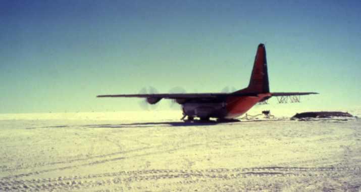
29 Photos from Martin Sharp and Jeff Kavanaugh (EAS) Antarctica One of the first applications of radar for measuring ice thickness was described by Walford (1964). Also called radio-echo sounding (RES). Radio waves travel at m/ns. General review of radar applications in glaciology given by Plewes and Hubbard (2001). Extensive data base collected in Antarctica in the 1960 s and 1970s using airborne radar system. More than 400,000 km of profile data collected Scott Polar Research Institute, NSF and Technical University of Denmark. Figures below are from 29


30 Recent compilation of ice thickness data in the BEDMAP project 30


31 31


32 Icepod / Rosetta project Looking at the Ross Ice Shelf with Airborne radar and other geophysical techniques 32
.")
33 Canadian Arctic Radar section from John Evans Glacier, Ellesmere Island. For details see Copland and Sharp (2001). Measuring ice thickness can confirm space geodetic studies of glacier volume. 33
.")
34 G4.9.2 Mapping internal structure of ice sheets and glaciers. Internal reflections believed to be due to isochronous layers. Layers of dust from volcanic eruptions can give strong reflections. Example below is taken from the Fletcher Promontory, Antarctica and the undulations in the isochronous layers are not correlated with bedrock topography (Vaughan et al., 1999). One feature occurs at an ice divide and reflects non-linear rheology of ice. Mapping this internal structure helps with interpretation of ice core data. The internal reflections can also used to understand flow pattern of glacier. 34
")
35 Vaughan et al., Nature, (1999) 35

36 Figure from Martin Sharp (EAS) Local-scale snow accumulation variability on the Greenland ice sheet from ground-penetrating radar (GPR) G4.9.3 Determine basal conditions Sub-glacial lakes first identified on the basis of character of a flat basal reflection, and flat ice surface. Lake Vostock was detected from both airborne and satellite radar. 36


37 More information Animation : Elsewhere the amplitude of the basal reflection can be used to study the composition of sub-glacial sediments. Reflections from a frozen base or one containing free water are quite different. This parameter is important for understanding how easily the glacier or ice sheet can move. For examples see Holt et al., (2006) who used airborne radar to infer that the bed of the Taylor Glacier is frozen. 37


38 G4.9.4 Crevasse detection Photos from Antarctica New Zealand in
39 G5 References Arcone SA (1996), High resolution of glacial ice stratigraphy: A ground-penetrating radar study of Pegasus Runway, McMurdo Station, Antarctica. Geophysics. 61(6): Best JL, PJ Ashworth, CS Bristow, and J Roden, Three-Dimensional Sedimentary Architecture of a Large, Mid-Channel Sand Braid Bar, Jamuna River, Bangladesh, J. of Sedimentary Research, : Copland L and Sharp M Mapping thermal and hydrological conditions beneath a polythermal glacier using radio echo sounding. Journal of Glaciology, 47, Davis JL, and P Annan, Ground-penetrating radar for high resolution mapping of soil and rock stratigraphy, Geophysical Prospecting, 37, , Grote, K., S. Hubbard, Y. Rubin, GPR monitoring of volumetric water content in soils applied to highway construction and maintenance, The Leading Edge, May, Holt JW, ME Peters, DL Morse, DD Blankenship, LE Lindzey, JL Kavanaugh and KM Cuffey, Identifying and characterizing subsurface echoes in airborne radar sounding data from a high clutter environment in Taylor Valley, Antarctica, 11 th International conference of Ground Penetrating radar, June 19-22, Columbus, Ohio, USA, Hubbard S, K Grote, Y Rubin, Mapping the volumetric soil water content of a California vineyard using high frequency GPR ground wave data, The Leading Edge, , June Huisman JA, S Hubbard, JD Redman and AP Annan, Measuring soil water content with groundpenetrating radar : A review, Vadose Zone Journal, 2(4), , Plewes LA and B Hubbard, A review of the use of radio echo sounding in glaciology, Progress in Physical Geography 2001; 25; 203, DOI: / Roth K, R Schulin, H Flühler, and W Attinger (1990), Calibration of Time Domain Reflectometry for Water Content Measurement Using a Composite Dielectric Approach, Water Resour. Res., 26(10), Topp GC, Davis JL, Annan AP, Electromagnetic determination of soil water content: measurements in coaxial transmission lines. Water Resources Research 16(3), Vaughan DG, HFJ Corr, CSM Doake, and ED Waddington (1999), Distortion of isochronous layers in ice revealed by ground-penetrating radar. Nature. 398: Walford MER (1964), Radio-echo sounding through an ice shelf. Nature. 204: Welch BC, WT Pfeffer, JT Harper and NF Humphrey (1998), Mapping subglacial surfaces of temperate valley glaciers by two-pass migration of radio-echo sounding survey data, Journal of Glaciology. 44: Winebrenner DP, BE Smith, GA Catania, HB Conway and CF Raymond (2003), Radiofrequency attenuation between Siple Dome, West Antarctica, from wide-angle and profiling radar observations. Annals of Glaciology. 37:
Ground Penetrating Radar (day 1) EOSC Slide 1
 EOSC Slide 1") Ground Penetrating Radar (day 1) Slide 1 Introduction to GPR Today s Topics Setup: Motivational Problems Physical Properties - Dielectric Permittivity and Radiowaves - Microwave Example Basic Principles:
Ground Penetrating Radar (day 1) Slide 1 Introduction to GPR Today s Topics Setup: Motivational Problems Physical Properties - Dielectric Permittivity and Radiowaves - Microwave Example Basic Principles:
7. Consider the following common offset gather collected with GPR.
 Questions: GPR 1. Which of the following statements is incorrect when considering skin depth in GPR a. Skin depth is the distance at which the signal amplitude has decreased by a factor of 1/e b. Skin
Applied Geophysics Nov 2 and 4
 Applied Geophysics Nov 2 and 4 Effects of conductivity Surveying geometries Noise in GPR data Summary notes with essential equations Some Case histories EOSC 350 06 Slide 1 GPR Ground Penetrating Radar
GPR Part II: Effects of conductivity. Surveying geometries. Noise in GPR data. Summary notes with essential equations. Some Case histories
 GPR Part II: Effects of conductivity Surveying geometries Noise in GPR data Summary notes with essential equations Some Case histories EOSC 350 06 Slide 1 GPR Ground Penetrating Radar R = ε ε 2 2 + ε ε
Radar Methods General Overview
 Environmental and Exploration Geophysics II Radar Methods General Overview tom.h.wilson tom.wilson@mail.wvu.edu Department of Geology and Geography West Virginia University Morgantown, WV Brown (2004)
Electromagnetic Induction
 Electromagnetic Induction Recap the motivation for using geophysics We have problems to solve Slide 1 Finding resources Hydrocarbons Minerals Ground Water Geothermal Energy SEG Distinguished Lecture slide
Ground Penetrating Radar
 Ground Penetrating Radar Begin a new section: Electromagnetics First EM survey: GPR (Ground Penetrating Radar) Physical Property: Dielectric constant Electrical Permittivity EOSC 350 06 Slide Di-electric
Downloaded from library.seg.org by on 10/26/14. For personal use only. SEG Technical Program Expanded Abstracts 2014
 Ground penetrating abilities of broadband pulsed radar in the 1 70MHz range K. van den Doel, Univ. of British Columbia, J. Jansen, Teck Resources Limited, M. Robinson, G. C, Stove, G. D. C. Stove, Adrok
GPR Data Acquisition and Interpretation
 1 GPR Data Acquisition and Interpretation Mezgeen Rasol PhD Candidate Geophysics and Seismic Engineering Polytechnic University of Catalonia mezgeen.rasol@upc.edu BIG-SKY-EARTH Cost Action TD143 Workshop
Archaeo-Geophysical Associates, LLC
 Geophysical Survey at the Parker Cemetery Rockwall, Texas. AGA Report 2010-6 Report Submitted To: Texas Cemetery Restoration 10122 Cherry Tree Dr. Dallas, Texas 75243 May 14, 2010 Chester P. Walker, Ph.D.
Pitfalls in GPR Data Interpretation: Differentiating Stratigraphy and Buried Objects from Periodic Antenna and Target Effects
 GEOPHYSICAL RESEARCH LETTERS, VOL. 27, NO. 20, PAGES 3393-3396, OCTOBER 15, 2000 Pitfalls in GPR Data Interpretation: Differentiating Stratigraphy and Buried Objects from Periodic Antenna and Target Effects
ωκε ωκε 5.11 Ground Penetrating Radar (GPR)
") 5. Ground Penetrating Radar (GPR) The plane wave solutions we have studied so far have been valid for frequencies and conductivities such that the conduction currents dominate the displacement currents
5. Ground Penetrating Radar (GPR) The plane wave solutions we have studied so far have been valid for frequencies and conductivities such that the conduction currents dominate the displacement currents
Experiment on Artificial Frozen Soil Boundary GPR Detection During Cross-passage Construction in Tunnels
 354 Progress In Electromagnetics Research Symposium 2005, Hangzhou, China, August 22-26 Experiment on Artificial Frozen Soil Boundary GPR Detection During Cross-passage Construction in Tunnels Yong-Hui
Understanding Seismic Amplitudes
 Understanding Seismic Amplitudes The changing amplitude values that define the seismic trace are typically explained using the convolutional model. This model states that trace amplitudes have three controlling
Here the goal is to find the location of the ore body, and then evaluate its size and depth.
 Geophysics 223 March 2009 D3 : Ground EM surveys over 2-D resistivity models D3.1 Tilt angle measurements In D2 we discussed approaches for mapping terrain conductivity. This is appropriate for many hydrogeology
SIMULATION OF GPR SCENARIOS USING FDTD
 SIMULATION OF GPR SCENARIOS USING FDTD 1 GAMIL ALSHARAHI, 2 ABDELLAH DRIOUACH, 3 AHMED FAIZE 1,2 Department of physic, Abdelmalek Essaâdi University, Faculty of sciences, Morocco 3 Department of physic,
Rec. ITU-R P RECOMMENDATION ITU-R P * ELECTRICAL CHARACTERISTICS OF THE SURFACE OF THE EARTH
 Rec. ITU-R P.527-3 1 RECOMMENDATION ITU-R P.527-3 * ELECTRICAL CHARACTERISTICS OF THE SURFACE OF THE EARTH Rec. 527-3 (1978-1982-1990-1992) The ITU Radiocommunication Assembly, considering a) that ground-wave
Application of Ground Penetrating Radar for River Ice Surveys
 CGU HS Committee on River Ice Processes and the Environment 14th Workshop on the Hydraulics of Ice Covered Rivers Quebec City, June 19-22, 2007 Application of Ground Penetrating Radar for River Ice Surveys
Advanced Ground Investigation Techniques to Help Limit Risk or Examine Failure. Advanced Subsurface Investigations
 Advanced Ground Investigation Techniques to Help Limit Risk or Examine Failure Overview Introduction What is geophysics? Why use it? Common Methods Seismic Ground Radar Electrical Case Studies Conclusion
The use of high frequency transducers, MHz, allowing the resolution to target a few cm thick in the first half meter suspect.
 METHODOLOGY GPR (GROUND PROBING RADAR). In recent years the methodology GPR (Ground Probing Radar) has been applied with increasing success under the NDT thanks to the high speed and resolving power. As
Ground Penetrating Radar Theory, Data Collection, Processing, and Interpretation: A Guide for Archaeologists
 Ground Penetrating Radar Theory, Data Collection, Processing, and Interpretation: A Guide for Archaeologists Created by: Lisa Dojack April 2012 Table of Contents Acknowledgments... i Foreword... ii Section
Identification of Pipelines from the Secondary Reflect Wave Travel Time of Ground-Penetrating Radar Waves
 Journal of Emerging Trends in Engineering and Applied Sciences (JETEAS) 2 (5): 770-774 Scholarlink Research Institute Journals, 2011 (ISSN: 2141-7016) jeteas.scholarlinkresearch.org Journal of Emerging
Developing improved techniques for GPR guided wave data analysis
 Scholars' Mine Masters Theses Student Theses and Dissertations Fall 2018 Developing improved techniques for GPR guided wave data analysis Yunyi Guan Follow this and additional works at: http://scholarsmine.mst.edu/masters_theses
This presentation was prepared as part of Sensor Geophysical Ltd. s 2010 Technology Forum presented at the Telus Convention Center on April 15, 2010.
 This presentation was prepared as part of Sensor Geophysical Ltd. s 2010 Technology Forum presented at the Telus Convention Center on April 15, 2010. The information herein remains the property of Mustagh
Seismic Reflection Method
 1 of 25 4/16/2009 11:41 AM Seismic Reflection Method Top: Monument unveiled in 1971 at Belle Isle (Oklahoma City) on 50th anniversary of first seismic reflection survey by J. C. Karcher. Middle: Two early
Rec. ITU-R P RECOMMENDATION ITU-R P *
 Rec. ITU-R P.682-1 1 RECOMMENDATION ITU-R P.682-1 * PROPAGATION DATA REQUIRED FOR THE DESIGN OF EARTH-SPACE AERONAUTICAL MOBILE TELECOMMUNICATION SYSTEMS (Question ITU-R 207/3) Rec. 682-1 (1990-1992) The
Propagation Mechanism
 Propagation Mechanism ELE 492 FUNDAMENTALS OF WIRELESS COMMUNICATIONS 1 Propagation Mechanism Simplest propagation channel is the free space: Tx free space Rx In a more realistic scenario, there may be
Geology 228/378 Environmental Geophysics Lecture 10. Electromagnetic Methods (EM) I And frequency EM (FEM)
 I And frequency EM (FEM)") Geology 228/378 Environmental Geophysics Lecture 10 Electromagnetic Methods (EM) I And frequency EM (FEM) Lecture Outline Introduction Principles Systems and Methods Case Histories Introduction Many EM
Geology 228/378 Environmental Geophysics Lecture 10 Electromagnetic Methods (EM) I And frequency EM (FEM) Lecture Outline Introduction Principles Systems and Methods Case Histories Introduction Many EM
GROUND PENETRATING RADAR (GPR)
") Introduction GROUND PENETRATING RADAR (GPR) (After Basson 2000) GPR is an electromagnetic (EM) geophysical method for high-resolution detection, imaging and mapping of subsurface soils and rock conditions.
Introduction GROUND PENETRATING RADAR (GPR) (After Basson 2000) GPR is an electromagnetic (EM) geophysical method for high-resolution detection, imaging and mapping of subsurface soils and rock conditions.
Tri-band ground penetrating radar for subsurface structural condition assessments and utility mapping
 Tri-band ground penetrating radar for subsurface structural condition assessments and utility mapping D. Huston *1, T. Xia 1, Y. Zhang 1, T. Fan 1, J. Razinger 1, D. Burns 1 1 University of Vermont, Burlington,
Ground Penetrating Radar (GPR) By Dr. Eng. Zubair Ahmed
 By Dr. Eng. Zubair Ahmed") Ground Penetrating Radar (GPR) By Dr. Eng. Zubair Ahmed Acknowledgement Golder Associates, Whitby, Ontario Stantec Consulting, Kitchener, Ontario Infrasense Inc. USA Geophysical Survey Systems Inc. (GSSI),
Ground Penetrating Radar (GPR) By Dr. Eng. Zubair Ahmed Acknowledgement Golder Associates, Whitby, Ontario Stantec Consulting, Kitchener, Ontario Infrasense Inc. USA Geophysical Survey Systems Inc. (GSSI),
Investigating multi-polarization GPR wave transmission through thin layers: Implications for vertical fracture characterization
 GEOPHYSICAL RESEARCH LETTERS, VOL. 33, L20401, doi:10.1029/2006gl027788, 2006 Investigating multi-polarization GPR wave transmission through thin layers: Implications for vertical fracture characterization
An acousto-electromagnetic sensor for locating land mines
 An acousto-electromagnetic sensor for locating land mines Waymond R. Scott, Jr. a, Chistoph Schroeder a and James S. Martin b a School of Electrical and Computer Engineering b School of Mechanical Engineering
HELICOPTER-BORNE GEOPHYSICAL SURVEY SYSTEMS
 HELICOPTER-BORNE GEOPHYSICAL SURVEY SYSTEMS APPLICATIONS: base & precious metals exploration diamondiferous kimberlite exploration geological mapping mapping of fault zones for engineering and mining applications
GPR SURVEY METHOD. Ground probing radar
 The ground penetrating radar (GPR - Ground Probing Radar) is a geophysical method used to investigate the near surface underground. Thanks to its high degree of resolution, the GPR is the most effective
L O C A T O R G P R. Introducing the. Radarteam. Ground Probing Radar/Antenna system with Rugged PC and Cart ü
 Introducing the L O C A T O R G P R Ground Probing Radar/Antenna system with Rugged PC and Cart ü Fully integrated system. Multi Frequency operation: 100-900 MHz ü Air/Ground Coupled operation. Multiple
ARCHAEOLOGICAL GEOPHYSICS: SENSOR SELECTION AND SITE SUITABILITY
 ARCHAEOLOGICAL GEOPHYSICS: SENSOR SELECTION AND SITE SUITABILITY A SPARC Webinar presented on October 17, 2014 Eileen G. Ernenwein, PhD ETSU: http://faculty.etsu.edu/ernenwei/ CAST: http://goo.gl/wyzlp
We are IntechOpen, the world s leading publisher of Open Access books Built by scientists, for scientists. International authors and editors
 We are IntechOpen, the world s leading publisher of Open Access books Built by scientists, for scientists 3,500 108,000 1.7 M Open access books available International authors and editors Downloads Our
Ultra-Wideband Radars for Measurements Over Land and Sea Ice
 Ultra-Wideband Radars for Measurements Over Land and Sea Ice R. Hale, H. Miller, S. Gogineni, J.-B. Yan, F. Rodriguez-Morales, C. Leuschen, Z. Wang, J. Paden, D. Gomez-Garcia, T. Binder, D. Steinhage,
The application of GPR for the modeling of ERT data and the evaluation of resolution for different electrode configurations
 BACHELOR THESIS The application of GPR for the modeling of ERT data and the evaluation of resolution for different TU Wien Department of Geodesy and Geoinformation Research Group Geophysics Performed by
Microwave Remote Sensing (1)
") Microwave Remote Sensing (1) Microwave sensing encompasses both active and passive forms of remote sensing. The microwave portion of the spectrum covers the range from approximately 1cm to 1m in wavelength.
Microwave Remote Sensing (1) Microwave sensing encompasses both active and passive forms of remote sensing. The microwave portion of the spectrum covers the range from approximately 1cm to 1m in wavelength.
Analysis of Crack Detection in Metallic and Non-metallic Surfaces Using FDTD Method
 ECNDT 26 - We.4.3.2 Analysis of Crack Detection in Metallic and Non-metallic Surfaces Using FDTD Method Faezeh Sh.A.GHASEMI 1,2, M. S. ABRISHAMIAN 1, A. MOVAFEGHI 2 1 K. N. Toosi University of Technology,
GPR MEASUREMENTS OF WATER LEVEL IN SILTY SOILS. Sandeep Pyakurel
 GPR MEASUREMENTS OF WATER LEVEL IN SILTY SOILS Sandeep Pyakurel Problem report submitted to the College of Engineering and Mineral Resources at West Virginia University in partial fulfillment of the requirements
Autonomous FMCW Radar Survey of Antarctic Shear Zone
 Boise State University ScholarWorks CGISS Publications and Presentations Center for Geophysical Investigation of the Shallow Subsurface (CGISS) 8-16-21 Autonomous FMCW Radar Survey of Antarctic Shear Zone
Experimental investigation of the acousto-electromagnetic sensor for locating land mines
 Proceedings of SPIE, Vol. 3710, April 1999 Experimental investigation of the acousto-electromagnetic sensor for locating land mines Waymond R. Scott, Jr. a and James S. Martin b a School of Electrical
# DEFINITIONS TERMS. 2) Electrical energy that has escaped into free space. Electromagnetic wave
 Electrical energy that has escaped into free space. Electromagnetic wave") CHAPTER 14 ELECTROMAGNETIC WAVE PROPAGATION # DEFINITIONS TERMS 1) Propagation of electromagnetic waves often called radio-frequency (RF) propagation or simply radio propagation. Free-space 2) Electrical
CHAPTER 14 ELECTROMAGNETIC WAVE PROPAGATION # DEFINITIONS TERMS 1) Propagation of electromagnetic waves often called radio-frequency (RF) propagation or simply radio propagation. Free-space 2) Electrical
FREQUENCY-DOMAIN ELECTROMAGNETIC (FDEM) MIGRATION OF MCSEM DATA SUMMARY
 MIGRATION OF MCSEM DATA SUMMARY") Three-dimensional electromagnetic holographic imaging in offshore petroleum exploration Michael S. Zhdanov, Martin Čuma, University of Utah, and Takumi Ueda, Geological Survey of Japan (AIST) SUMMARY Off-shore
Three-dimensional electromagnetic holographic imaging in offshore petroleum exploration Michael S. Zhdanov, Martin Čuma, University of Utah, and Takumi Ueda, Geological Survey of Japan (AIST) SUMMARY Off-shore
Geophysical Survey Rock Hill Bleachery TBA Site Rock Hill, South Carolina EP-W EPA, START 3, Region 4 TABLE OF CONTENTS Section Page Signature
 Geophysical Survey Rock Hill Bleachery TBA Site Rock Hill, South Carolina EP-W-05-054 EPA, START 3, Region 4 Prepared for: Tetra Tech EM, Inc. October 12, 2012 Geophysical Survey Rock Hill Bleachery TBA
GEOPIC, Oil & Natural Gas Corporation Ltd, Dehradun ,India b
 Estimation of Seismic Q Using a Non-Linear (Gauss-Newton) Regression Parul Pandit * a, Dinesh Kumar b, T. R. Muralimohan a, Kunal Niyogi a,s.k. Das a a GEOPIC, Oil & Natural Gas Corporation Ltd, Dehradun
P Forsmark site investigation. RAMAC and BIPS logging in borehole HFM11 and HFM12
 P-04-39 Forsmark site investigation RAMAC and BIPS logging in borehole HFM11 and HFM12 Jaana Gustafsson, Christer Gustafsson Malå Geoscience AB/RAYCON March 2004 Svensk Kärnbränslehantering AB Swedish
RADAR INSPECTION OF CONCRETE, BRICK AND MASONRY STRUCTURES
 RADAR INSPECTION OF CONCRETE, BRICK AND MASONRY STRUCTURES C.P.Hobbs AEA Industrial Technology Materials and Manufacturing Division Nondestructive Testing Department Building 447 Harwell Laboratory Oxon
ANALYSIS OF RADIO WAVE PROPAGATION IN SOIL WITH APPLICATION IN ARCHEOLOGY
 ANALYSIS OF RADIO WAVE PROPAGATION IN SOIL WITH APPLICATION IN ARCHEOLOGY A. CHELMUS, D. ENE, L. ANGHELUTA National Institute for Research and Development in Optoelectronics-INOE 2000, Atomistilor str.
Statement of Qualifications
 Revised January 29, 2011 ClearView Geophysics Inc. 12 Twisted Oak Street Brampton, ON L6R 1T1 Canada Phone: (905) 458-1883 Fax: (905) 792-1884 general@geophysics.ca www.geophysics.ca 1 1. Introduction
Session2 Antennas and Propagation
 Wireless Communication Presented by Dr. Mahmoud Daneshvar Session2 Antennas and Propagation 1. Introduction Types of Anttenas Free space Propagation 2. Propagation modes 3. Transmission Problems 4. Fading
Seismic reflection method
 Seismic reflection method Seismic reflection method is based on the reflections of seismic waves occurring at the contacts of subsurface structures. We apply some seismic source at different points of
GeoRadar Division. GPR for Archeology and Cultural Heritage. GeoRadar Division. GPR Configuration for Archeology and Cultural Heritage Application
 GeoRadar Division GPR Configuration for Archeology and Cultural Heritage Application We believe that the Archaeological patrimony and the Cultural Heritage are one of the most important aspect of this
A low-frequency ice-penetrating radar system adapted for use from an airplane: test results from Bering and Malaspina Glaciers, Alaska, USA
 Annals of Glaciology 51 2009 93 A low-frequency ice-penetrating radar system adapted for use from an airplane: test results from Bering and Malaspina Glaciers, Alaska, USA Howard CONWAY, 1 Ben SMITH, 1
Experimental quantification of bulk sampling volume of ECH 2 O soil moisture sensors
 Hydrology Days 29 Experimental quantification of bulk sampling volume of ECH 2 O soil moisture sensors Anuchit Limsuwat 1, Toshihiro Sakaki 1, Tissa H. Illangasekare 1 Center for Experimental Study of
Using GPR Technique Assessment for Study the Sub-Grade of Asphalt and Concrete Conditions
 Using GPR Technique Assessment for Study the Sub-Grade of Asphalt and Concrete Conditions Alaa S. Mahdi Remote Sensing Unit, College of Science, University of Baghdad, Baghdad, Iraq Abstract The Ground
Resolution in evaluation of structural elements by using ground-penetrating radar.
 Resolution in evaluation of structural elements by using ground-penetrating radar. V. Perez-Gracia Departamento de Resistencia de Materiales y Estructuras en la Ingeniería. EUETIB/CEIB. Universidad Politécnica
Power loss in dipping internal reflectors, imaged using ice-penetrating radar
 Annals of Glaciology 55(67) 2014 doi: 10.3189/2014AoG67A005 49 Power loss in dipping internal reflectors, imaged using ice-penetrating radar Nicholas HOLSCHUH, 1 Knut CHRISTIANSON, 2 Sridhar ANANDAKRISHNAN
Estimating Debye Parameters from GPR Reflection Data Using Spectral Ratios
 Boise State University ScholarWorks Geosciences Faculty Publications and Presentations Department of Geosciences 9-7-2009 Estimating Debye Parameters from GPR Reflection Data Using Spectral Ratios John
Resolutionof Ground-penetrating Radar Reflections at Differing Frequencies
 Archaeological Prospection Archaeol. Prospect. 13, 141 145 (2006) Published online in Wiley InterScience (www.interscience.wiley.com). DOI: 10.1002/arp.283 Resolutionof Ground-penetrating Radar Reflections
UNIVERSITI MALAYSIA PERLIS
 UNIVERSITI MALAYSIA PERLIS SCHOOL OF COMPUTER & COMMUNICATIONS ENGINEERING EKT 341 LABORATORY MODULE LAB 2 Antenna Characteristic 1 Measurement of Radiation Pattern, Gain, VSWR, input impedance and reflection
Electrical Resistivity Imaging
 Approved for Public Release; Distribution Unlimited Electrical Resistivity Imaging David Hull US Army Research Lab hull@arl.army.mil 17 Jun 2009 ARL Workshop on Personnel, Vehicle, and Tunnel Detection
Investigation of Bridge Decks Utilizing Ground Penetrating Radar
 Investigation of Bridge Decks Utilizing Ground Penetrating Radar Steve Cardimona *, Brent Willeford *, John Wenzlick +, Neil Anderson * * The University of Missouri-Rolla, Department of Geology and Geophysics
Detection of Obscured Targets
 Detection of Obscured Targets Waymond R. Scott, Jr. and James Mcclellan School of Electrical and Computer Engineering Georgia Institute of Technology Atlanta, GA 30332-0250 waymond.scott@ece.gatech.edu
Effect of Frequency and Migration Aperture on Seismic Diffraction Imaging
 IOP Conference Series: Earth and Environmental Science PAPER OPEN ACCESS Effect of Frequency and Migration Aperture on Seismic Diffraction Imaging To cite this article: Y. Bashir et al 2016 IOP Conf. Ser.:
INTRODUCTION TO ONSHORE SEISMIC ACQUISITION AND PROCESSING
 INTRODUCTION TO ONSHORE SEISMIC ACQUISITION AND PROCESSING SEPTEMBER 2017 1 SIMPLIFIED DIAGRAM OF SPLIT SPREAD REFLECTION SEISMIC DATA ACQUISITION RECORDING TRUCK ENERGY SOURCE SHOTPOINTS 1 2 3 4 5 6 7
EKKO_Project is the all-inclusive software SUBSURFACE VIEWS. EKKO_Project V4 Released. In this issue GPR INNOVATIONS HARDWARE AND SOFTWARE
 SUBSURFACE VIEWS GPR INNOVATIONS HARDWARE AND SOFTWARE In this issue 1, 2, 3 EKKO_Project V4 Released 3, 4 EAGE 2015 Boot Camp 5, 6 TIPS: Using the Water Table to Add Topography January, 2016 - Vol. 12,
VALIDATION OF GROUND PENETRATING RADAR DATA INTERPRETATION USING AN ELECTROMAGNETIC WAVE PROPAGATION SIMULATOR
 Romanian Reports in Physics, Vol. 68, No. 4, P. 1584 1588, 2016 VALIDATION OF GROUND PENETRATING RADAR DATA INTERPRETATION USING AN ELECTROMAGNETIC WAVE PROPAGATION SIMULATOR A. CHELMUS National Institute
10 Radar Imaging Radar Imaging
 10 Radar Imaging Active sensors provide their own source of energy to illuminate the target. Active sensors are generally divided into two distinct categories: imaging and non-imaging. The most common
In search of a Historic Grave: GPR Investigation near the Yellowstone Lake Store: 7/15/2010
 In search of a Historic Grave: GPR Investigation near the Yellowstone Lake Store: 7/15/2010 Steven Sheriff Professor of Geophysics Department of Geosciences University of Montana Missoula, Montana Introduction
GCM mapping Vildbjerg - HydroGeophysics Group - Aarhus University
 GCM mapping Vildbjerg - HydroGeophysics Group - Aarhus University GCM mapping Vildbjerg Report number 06-06-2017, June 2017 Indholdsfortegnelse 1. Project information... 2 2. DUALEM-421s... 3 2.1 Setup
Advanced Utility Locating Technologies (R01B)
") Advanced Utility Locating Technologies (R01B) Jacob Sheehan Senior Geophysicist Olson Engineering Phil Sirles Principal Geophysicist Olson Engineering Introduction: Utility Bundle Overview SHRP2 Strategic
Advanced Utility Locating Technologies (R01B) Jacob Sheehan Senior Geophysicist Olson Engineering Phil Sirles Principal Geophysicist Olson Engineering Introduction: Utility Bundle Overview SHRP2 Strategic
MICROWAVE THICKNESS MEASUREMENTS OF MAGNETIC COATINGS. D.D. Palmer and V.R. Ditton
 MICROWAVE THICKNESS MEASUREMENTS OF MAGNETIC COATINGS D.D. Palmer and V.R. Ditton McDonnell Aircraft Company McDonnell Douglas Corporation P.O. Box 516 St. Louis, MO 63166 INTRODUCTION Microwave nondestructive
Anisotropic Frequency-Dependent Spreading of Seismic Waves from VSP Data Analysis
 Anisotropic Frequency-Dependent Spreading of Seismic Waves from VSP Data Analysis Amin Baharvand Ahmadi* and Igor Morozov, University of Saskatchewan, Saskatoon, Saskatchewan amin.baharvand@usask.ca Summary
Radar Imaging Wavelengths
 A Basic Introduction to Radar Remote Sensing ~~~~~~~~~~ Rev. Ronald J. Wasowski, C.S.C. Associate Professor of Environmental Science University of Portland Portland, Oregon 3 November 2015 Radar Imaging
Reflector Antenna, its Mount and Microwave. Absorbers for IIP Radiometer Experiments
 Reflector Antenna, its Mount and Microwave Absorbers for IIP Radiometer Experiments Nakasit Niltawach, and Joel T. Johnson May 8 th, 2003 1 Introduction As mentioned in [1], measurements are required for
7. Experiment K: Wave Propagation
 7. Experiment K: Wave Propagation This laboratory will be based upon observing standing waves in three different ways, through coaxial cables, in free space and in a waveguide. You will also observe some
Old & New? INTRODUCTION. The Best Proximal Geophysical Detector Ever!
 Measuring Soil Conductivity with Geonics Limited Electromagnetic Geophysical Instrumentation INTRODUCTION This presentation will briefly discuss the principles of operation and the practical applications
RECONSTRUCTION OF BURIED OBJECTS BY IMPLEMENTATION OF GROUND PENETRATING RADAR TECHNIQUE: EXAMPLE ON ROMAN TOMB IN BRESTOVIK (SERBIA)
") Geoarchaeology and Archaeomineralogy (Eds. R. I. Kostov, B. Gaydarska, M. Gurova). 2008. Proceedings of the International Conference, 29-30 October 2008 Sofia, Publishing House St. Ivan Rilski, Sofia,
Geoarchaeology and Archaeomineralogy (Eds. R. I. Kostov, B. Gaydarska, M. Gurova). 2008. Proceedings of the International Conference, 29-30 October 2008 Sofia, Publishing House St. Ivan Rilski, Sofia,
We are IntechOpen, the world s leading publisher of Open Access books Built by scientists, for scientists. International authors and editors
 We are IntechOpen, the world s leading publisher of Open Access books Built by scientists, for scientists 3,900 116,000 120M Open access books available International authors and editors Downloads Our
Electromagnetic soil properties variability in a mine-field trial site in Cambodia
 Electromagnetic soil properties variability in a mine-field trial site in Cambodia Ainhoa G. Gorriti a,antoniorañada-shaw a,arnoldj.schoolderman a, Jan B. Rhebergen a and Evert C. Slob. b a TNO Defence,
GPR Investigation: Post Tension Cable Mapping
 CMD Civil Pty Ltd PO Box 1119 Huntingdale VIC 3166 +61 3 9544 8833 info@cmdcivil.com www.cmdcivil.com Case Study: GPR Investigation: Post Tension Cable Mapping This application note demonstrates an example
Lecture Series SGL 308: Introduction to Geological Mapping Lecture 8 LECTURE 8 REMOTE SENSING METHODS: THE USE AND INTERPRETATION OF SATELLITE IMAGES
 LECTURE 8 REMOTE SENSING METHODS: THE USE AND INTERPRETATION OF SATELLITE IMAGES LECTURE OUTLINE Page 8.0 Introduction 114 8.1 Objectives 115 115 8.2 Remote Sensing: Method of Operation 8.3 Importance
Interferometric Approach to Complete Refraction Statics Solution
 Interferometric Approach to Complete Refraction Statics Solution Valentina Khatchatrian, WesternGeco, Calgary, Alberta, Canada VKhatchatrian@slb.com and Mike Galbraith, WesternGeco, Calgary, Alberta, Canada
Radar Reprinted from "Waves in Motion", McGourty and Rideout, RET 2005
 Radar Reprinted from "Waves in Motion", McGourty and Rideout, RET 2005 What is Radar? RADAR (Radio Detection And Ranging) is a way to detect and study far off targets by transmitting a radio pulse in the
Soil Moisture Observation Utilizing Reflected GNSS Signals
 Soil Moisture Observation Utilizing Reflected GNSS Signals GNSS-R Tech in Soil Moisture New Data Processing Method Prof. Dongkai YANG Joint African/Asia-Pacific UN-Regional Centers and International Training
Prototype Software-based Receiver for Remote Sensing using Reflected GPS Signals. Dinesh Manandhar The University of Tokyo
 Prototype Software-based Receiver for Remote Sensing using Reflected GPS Signals Dinesh Manandhar The University of Tokyo dinesh@qzss.org 1 Contents Background Remote Sensing Capability System Architecture
THE BEST GPR DATA QUALITY AT THE BEST PRICE! GROUND PENETRATING RADAR ZOND-12e G R O U N D P E N E T R A T I N G R A D A R S
 GROUND PENETRATING RADAR ZOND-12e General Purpose Pulse GPR ZOND-12e SINGLE CHANNEL OR ADVANCED CONTROL UNITS ZOND 12e GPR is a portable digital Ground Penetrating Radar carried by a single operator. The
Report. Mearns Consulting LLC. Former Gas Station 237 E. Las Tunas Drive San Gabriel, California Project # E
 Mearns Consulting LLC Report Former Gas Station 237 E. Las Tunas Drive San Gabriel, California Project #1705261E Charles Carter California Professional Geophysicist 20434 Corisco Street Chatsworth, CA
Detection of Multipath Propagation Effects in SAR-Tomography with MIMO Modes
 Detection of Multipath Propagation Effects in SAR-Tomography with MIMO Modes Tobias Rommel, German Aerospace Centre (DLR), tobias.rommel@dlr.de, Germany Gerhard Krieger, German Aerospace Centre (DLR),
Laboratory measurement of fragmented ore bulk density using ground penetrating radar
 Author(s): Benter, A.M. ; Moore, W. ; Antolovich, M. Title: Laboratory measurement of fragmented ore bulk density using ground penetrating radar Journal: Mining Technology: Transactions of the Institute
Helicopter Hard-mounted GPR Snow and Ice Thickness Measurement Systems. Call-up Number: # F
 Helicopter Hard-mounted GPR Snow and Ice Thickness Measurement Systems Call-up Number: # F5955-09-0319 by Sensors by Design, Ltd. 217 Lorne Avenue Newmarket, Ontario L3Y 4K5 Prepared for: Dr. Simon Prinsenberg
Rec. ITU-R P RECOMMENDATION ITU-R P PROPAGATION BY DIFFRACTION. (Question ITU-R 202/3)
") Rec. ITU-R P.- 1 RECOMMENDATION ITU-R P.- PROPAGATION BY DIFFRACTION (Question ITU-R 0/) Rec. ITU-R P.- (1-1-1-1-1-1-1) The ITU Radiocommunication Assembly, considering a) that there is a need to provide
Rec. ITU-R P.- 1 RECOMMENDATION ITU-R P.- PROPAGATION BY DIFFRACTION (Question ITU-R 0/) Rec. ITU-R P.- (1-1-1-1-1-1-1) The ITU Radiocommunication Assembly, considering a) that there is a need to provide
Evaluation of Ice-Coupled and Elevated GPR Antenna Acquisition on Ice
 Evaluation of Ice-Coupled and Elevated GPR Antenna Acquisition on Ice Tyler MacFarlane and Robert J. Ferguson ABSTRACT Elevated ice radar Two acquisition methods for near surface Ground Penetrating Radar
Covert Tunnel Detection Technologies
 2015 Covert Tunnel Detection Technologies Homeland Security Research Corp. Covert Tunnel Detection Technologies 2015 August 2015 Homeland Security Research Corp. (HSRC) is an international market and technology
Annex 5. Determination of the interference field strength in the Land Mobile Service
 Annex 5 Determination of the interference field strength in the Land Mobile Service Annex 5, page 2 of 18 1 General 1.1 This calculation method is based on Recommendation ITU-R P.1546, taking into account
ATS 351 Lecture 9 Radar
 ATS 351 Lecture 9 Radar Radio Waves Electromagnetic Waves Consist of an electric field and a magnetic field Polarization: describes the orientation of the electric field. 1 Remote Sensing Passive vs Active