Recent Development of SFCL in the USA
|
|
|
- Robert Carson
- 5 years ago
- Views:
Transcription


1 superior performance. powerful technology. Recent Development of SFCL in the USA Juan-Carlos H. Llambes, Ph.D. SFCL Program Manager / Senior High Voltage Engineer 23 rd International Superconductivity Symposium ISS2010 Nov 1-3, 2010 Tsukuba, Japan SuperPower, Inc. is a subsidiary of Royal Philips Electronics N.V.
2 Zenergy HTS Superconducting DC Magnet FCL SuperLimiter Fault Current Limiter Waukesha SFCL Transformer SuperPower s SFCL SFCL Summary 2

3 Zenergy s Inductive Saturating 1G FCL Concept Project Title: Design, Test and Demonstration of Saturable-Core Reactor HTS Fault Current Limiter Organization and Partners: Zenergy Power Inc Los Alamos National Laboratory 3
4 Zenergy s Inductive Saturating 1G FCL Concept Presently, Zenergy has designed and tested a commercial 12kV SFCL and is intending to complete the design of a 138kV demonstration device based on host utility input and initiate construction of 1 phase of a 3-phase device The HTS material is used only to form a very strong electromagnet the DC coil that saturates an iron core inside the AC coils with a DC magnetic flux In this device, the AC line current of the power grid is always carried by conventional copper conductors formed into AC coils It is the large AC fault current that drives the AC iron core out of saturation, increasing the AC reactance and thereby limiting the current that flows in the power grid and acts as an auto-reactor 4


5 Zenergy s Inductive Saturating HTS FCL Concept Inductive saturating FCL concept employs HTS technology to normally saturate the iron with a single DC magnet Inductance (H) Equivalent FCL inductance showing low inductance at small currents and nonlinear inductance increase at high currents for positive and negative values Current (ka) 5

6 Zenergy s Inductive Saturating 12kV FCL Concept 6
 Middle: Prototype device of just AC coils and magnets 2.6 m 2 footprint (2 x 1.3m) Right: Future 15 kv design prototype of 2.")
7 Zenergy s Inductive Saturating HTS FCL Concept Left: FCL demonstration device 6.25 m 2 footprint (2.5m x 2.5m) Middle: Prototype device of just AC coils and magnets 2.6 m 2 footprint (2 x 1.3m) Right: Future 15 kv design prototype of 2.55m 2 footprint (1.8m OD) 7

8 Current Testing and Performance of 12kV SFCL Gain impedance for a FCL saturable-core is 4-5 while for a conventional Current-Limiter-Reactor (CLR) is about 2. The SFCL demonstration shows a 20% fault reduction after 23 cycles of prospective fault current and 16% limitation at 1 st peak. Loss of substation power and shut down of the DC magnet. Proper operation of the SFCL depends on the power to excite the Magnet. Cryogenics and power in the DC magnet comes back to normal operation after the substation power is restored. 8
9 Zenergy 1G HTS Superconducting DC Magnet FCL SuperLimiter Fault Current Limiter Waukesha SFCL Transformer SuperPower s SFCL SFCL Summary 9
10 SuperLimiter Fault Current Limiter Project Title: Development and In-Grid Demonstration of a Voltage SuperLimiter Fault Current Limiter Organization and Partners: American Superconductor Corporation Southern California Edison Siemens AG Nexans GmbH & Co. KG 10
11 SuperLimiter Fault Current Limiter American Superconductor (AMSC) is addressing the development and in-grid testing of a 3-phase, high-voltage, 138-kV resistive FCL called SuperLimiter The SuperLimiter features a proprietary Siemens-developed, low inductance bifilar coil technology that makes the FCL invisible to the grid until it switches to a resistive state After 3 cycles of fault, the coils are disconnected from the power, switching the power to a reactor, to allow the 2G bifilar coils to recover without load The design uses high voltage components developed by Nexans and demonstrated on the DOE-funded LIPA cable project AMSC is employing resistive SFCLs because they are expected to be simpler and more compact in design 11
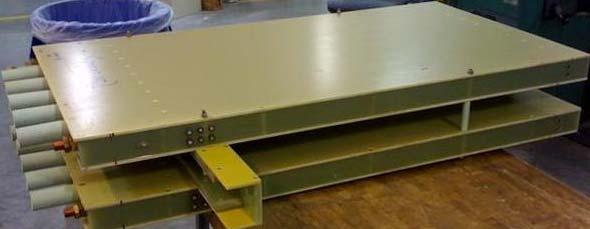
12 SuperLimiter Fault Current Limiter Prototype SFCL system for 115kV Nominal Voltage, 900A, 63 ka prospective, limited to 40kA. 12


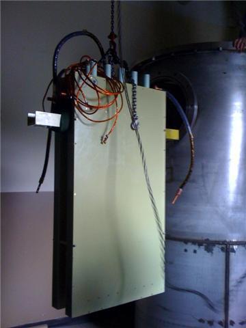
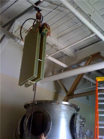
13 SuperLimiter Fault Current Limiter Horizontal stainless steel Dewar facilitates the assembly of the bifilar coil setup 13
 Voltage per length of the stainless steel is 56 Vrms/m Thus rated voltage is 56 Vrms/m x 26 m/coil x 21 coils = 30.6 kvrms 30.")
14 SuperLimiter Fault Current Limiter The module comprises 21 sub-assemblies, each containing 3 parallel coils, i.e. 63 coils in total Quench current is 3 x 2 x 260 A x 1.3 = 2028 A at 74 K (Ic of 1 tape = 260A) Voltage per length of the stainless steel is 56 Vrms/m Thus rated voltage is 56 Vrms/m x 26 m/coil x 21 coils = 30.6 kvrms 30.6 kvrms is lower than phase to ground voltage at 115 kv owing to the shunted limiter concept - voltage The modular approach comprises 21 sub-assemblies containing 3 parallel coils each. Therefore, the module contains a total of 63 bifilar coils. 14

15 SuperLimiter Fault Current Limiter Maximum load coils are subjected to under nominal condition is Rmax/R295 = 106 % (~350 K) 15
16 Zenergy 1G HTS Superconducting DC Magnet FCL SuperLimiter Fault Current Limiter Waukesha SFCL Transformer SuperPower s SFCL SFCL Summary 16

17 Waukesha SFCL Transformer SFCL Project: HTS Transformer R&D by Waukesha Electric Systems Organization and Partners: Waukesha Electric Systems Oak Ridge National Laboratory Southern California Edison SuperPower Inc. 17
18 Waukesha SFCL Transformer The objective of the project is to demonstrate the technical and economic feasibility and benefits of HTS transformers in ratings of 10 MVA and above To develop a 28-MVA, 69-kV fault-current-limiting (FCL) HTS transformer for the DOE Smart Grid Initiative The ultimate goal is to fabricate and test a pre-commercial prototype HTS transformer operating at transmission level voltages in the 138-kV class To speed the addition of HTS transformers to Waukesha s product line, WES intends to use as much of its conventional transformer manufacturing technology as possible The project supports DOE s mission to develop revolutionary power equipment using HTS wires 18
 Alpha-2 (1 Phase with HTS conductor) Waukesha manufacturing techniques will utilize experienced coil")
19 Waukesha SFCL Transformer Main Components: Uses Waukesha design software and ORNL design spreadsheet Coil Dewar surrounds warm steel core Air-cooled core with blower Proof-of-concept divided into: Alpha-1 (1 Phase with normal conductor) Alpha-2 (1 Phase with HTS conductor) Waukesha manufacturing techniques will utilize experienced coil winders 19

20 Waukesha SFCL Transformer Transformer Design: Original design used parallel copper Motivated by ANSI requirement for a conventional non-fcl transformer to recover normal operation after a 2-sec fault Disadvantages of using thick stabilizer: Copper produces high eddy current losses Evaluating alloy options for replacing copper Fault current will be reduced to about ½ that of conventional unit SCE substation opening time is ~1 sec in area of interest for 28 MVA HTS Transformer design will be based on known engineering of conventional transformer design. 20

21 Waukesha SFCL Transformer Standard WES design: Copper conductor with WES polymer insulation LV & HV disc windings Bushing Test Commercial 650 kv BIL bushing successfully tested in FY09 Commercial HV bushings 650kV testing has been successfully tested in the standard Waukesha LV and HV disc design. 21

22 Waukesha SFCL Transformer AC Losses: AC losses ~ (Ipeak/Ic)n Losses are similar for cowound Cu and Stainless For Ipeak/Ic < 0.4, n ~ 1.5 Consistent with ferromagnetic Ni-W Substrate For Ipeak/Ic > 0.4, n ~ 2 Eddy or coupling mechanism AC losses shown in HTS/Cu stabilizer are the largest ~100 (mw/m) 22
23 Zenergy 1G HTS Superconducting DC Magnet FCL SuperLimiter Fault Current Limiter Waukesha SFCL Transformer SuperPower s SFCL SFCL Summary 23
24 SuperPower s SFCL Project Title: SuperPower 2G Modular SFCL Device for Distribution and Power Lines Organization and Partners: SuperPower Inc. University of Houston Florida State University Oak Ridge National Laboratory Rensselaer Polytechnic Institute 24
25 SuperPower s SFCL The current project purpose is focused on the development of based modules for a superconducting fault current limiter for operation at voltage levels up to transmission level This modular design allow us to scale up validated module voltages and currents in order to accomplish both Distribution and levels This design consists of parallel elements and conventional copper coils. By using a cold shunt coil, no external or ancillary components or equipment are required; the device is self-contained SuperPower s design also offers Recovery Under Load (RUL) capabilities. RUL enables the device to recover to the superconducting state while carrying load current from other (non-faulted) lines 25
26 Modular SFCL system design components integration Modular SFCL device design specifications Shunt Coils Zsh = Rsh + jxsh, X/R ratio, EM force withstand, thermal and electrical properties, connectors, size, weight, over-banding, ease of assembly and manufacturablity HTS assembly Tape per element, RUL per element, element energy capability, connectors, size, cooling orientation, failure mechanisms and mitigation, losses and their effects on cryogenics design HV design LN2 and GN2 design stress criteria, spacing between tapes, elements and modules, stress shield dimensions, using solid barriers or not, bushings and assembly integration, assembly supporting structure (post insulators), overall assembly to cryostat spacing and integration Cryogenics LN2 flow control, LN2 and GN2 interface, pressurizing, safety issues, thermal handling of fault and steady state losses Sub-cooled Improves the Recovery Under Load performance and enhances current carry capabilties. Improvement of LN 2 dielectrics Pressurized LN 2 helps to increase dielectric properties, avoiding bubbles and lowering breakdown voltage probability. Shunt Coils HTS assembly 26


27 SFCL module manufacturing and assembly 2 nd Assembly of Supports 1 st SFCL Module Manufacturing 4 th Module Installation 5 th Internal Installation 3 rd Assembly of Connections 27


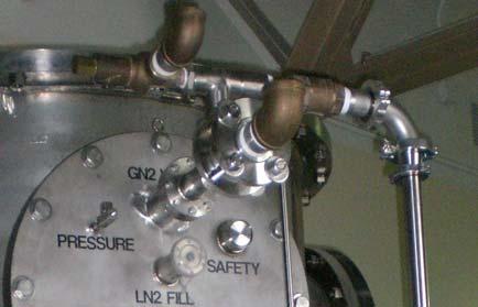


28 QF40 Port Vacuum Line 1 Thermocouples Digital Pressure Gage LN2 Main Filling Port High Voltage Bushings Vacuum Line 2 Pressure Valve Vacuum Lines Pressure Burst Disk Pressure Valve Pressure Gage Main Vacuum Valve Vacuum Line 1 28
 90kA Prospective is limited to 30 ka at 1 st peak and 20kA at 5 th.")
.")
29 SFCL Fault Current Dynamics 90 ka Prospective Fault 30 ka (66% Limited) 20 ka (77% Limited) 90kA Prospective is limited to 30 ka at 1 st peak and 20kA at 5 th. RUL Power recovered for the 3 first AEP Re-closure Sequence Faults. SFCL Voltage versus different X/R ratios (baseline, 200%, 300%). RUL versus different X/R ratios (baseline, 200%, 300%). 29
 Current at different frequencies play a critical")
30 Peak load current per tape and voltage for 74K and 77K Sub-cooled conditions at 74K improves voltage in 192% and current in 132%, a total of ~253% increase in power. A single circuit of 2 tapes in a SFCL module will limit 65% of 1 st peak fault in the entire voltage range (up to 25kA prospective tested at CAPS) Current at different frequencies play a critical role in percentage limitation, showing how important is to select the adequate reactance. Different tape architecture also plays an important role in the overall system percentage fault limitation at different frequencies. 30


31 Generalized SFCL specification development A Distribution SCFL 11-15kV phase, 800-2KA rms load current will limit ~65-75% when assembled with 3 SFCL modules 1.25m 2.5m Distribution SCFL 15kV phase illustration A SCFL 138kV phase, 1700A rms load, 40kA prospective will limit ~65-75% if assembled with 14 SFCL modules 1.25m 2.5m SCFL 138kV phase illustration 31
32 Zenergy 1G HTS Superconducting DC Magnet FCL SuperLimiter Fault Current Limiter Waukesha SFCL Transformer SuperPower s SFCL SFCL Summary 32


33 Zenergy 12kV SFCL Waukesha 66kV SFCL XFR SuperLimiter 115kV SFCL SuperPower 138kV SFCL 33
34 SFCL Summary Zenergy Zenergy Distribution AMSC Waukesha (Transformer / SFCL) SuperPower SuperPower Distribution Line Voltage (kv) 138kV 12kV 115kV 66kV / 12kV 138kV 15kV Load Current (A) 1,840A 800A 900A 425A / 2,300A 1,840A 2,300A Power (MVA) 254 MVA 9.6 MVA 104 MVA 28MVA 254 MVA 34.5MVA Prospective Fault 27kA 23kA 63kA 20kA 40-90kA 40-90kA Limited Fault 9.5kA 18.4kA 40kA 10kA 10-20kA ka Limited (%/100%) 50% 20% 36% 50% 66%-77% 66%-77% Limiting Type Inductive Inductive Superconductor 1G/ 1G/ Basic Technology (Reliability) -1G/ Wire -Iron Core -Reactor -1G/ Wire -Iron Core -Reactor - Wire -HV Switches -Shunt Reactor - Wire -Iron Core - Wire -Shunt or Reactor - Wire -Shunt or Reactor Temperature (K) 68K 68K 74K 70K-77K 68K-77K 68K-77K Recovery Load RUL Capable RUL Capable Non-RUL Non-RUL RUL Capable RUL Capable Multiple Faults Instantaneous Instantaneous After 16 sec After Minutes Instantaneous Instantaneous Fault Duration 3 Cycles Less than 2 sec Controls Required -Magnet Switch -Magnet Switch -2G-Coil -HV Switches -Non-RUL Switch -No Controls are necessary. -No Controls are necessary. Passive Systems Reactor Reactor Transformer 100% Passive 100% Passive Active Systems Magnet Ctrl. Magnet Ctrl. Non-RUL Ctrl. HV Switch Ctrl. Non-RUL Ctrl. Ground footprint NA 6.25 m 2 20 m 2 10 m 2 6 m 2 2 m 2 MVA / Footprint NA 1.5 (MVA / m 2 ) 5.2 (MVA/m 2 ) 2.8 (MVA / m 2 ) 42.3 (MVA / m 2 ) 17.2 (MVA / m 2 ) 34
35 SFCL Summary Zenergy Zenergy Distribution AMSC Waukesha (Transformer / SFCL) SuperPower SuperPower Distribution Line Voltage (kv) 138kV 12kV 115kV 66kV / 12kV 138kV 15kV Load Current (A) 1,840A 800A 900A 425A / 2,300A 1,840A 2,300A Power (MVA) 254 MVA 9.6 MVA 104 MVA 28MVA 254 MVA 34.5MVA Prospective Fault 27kA 23kA 63kA 20kA 40-90kA 40-90kA Limited Fault 9.5kA 18.4kA 40kA 10kA 10-20kA ka Limited (% / 100%) 50% 20% 36% 50% 66%-77% 66%-77% Limiting Type Inductive Inductive Superconductor 1G/ 1G/ Basic Technology (Reliability) -1G/ Wire -Iron Core -Reactor -1G/ Wire -Iron Core -Reactor SFCL - Wire Power - Wire -HV Switches -Iron Core -Shunt Reactor - Wire -Shunt or Reactor - Wire -Shunt or Reactor Temperature (K) 68K 68K 74K 70K-77K 68K-77K 68K-77K Recovery Load Multiple Faults RUL Capable Instantaneous Characteristics RUL Capable Non-RUL Non-RUL RUL Capable Instantaneous After 16 sec After Minutes Instantaneous RUL Capable Instantaneous Fault Duration 3 Cycles Less than 2 sec Controls Required -Magnet Switch -Magnet Switch -2G-Coil -HV Switches -Non-RUL Switch -No Controls are necessary. -No Controls are necessary. Passive Systems Reactor Reactor Transformer 100% Passive 100% Passive Active Systems Magnet Ctrl. Magnet Ctrl. Non-RUL Ctrl. HV Switch Ctrl. Non-RUL Ctrl. Ground footprint NA 6.25 m 2 20 m 2 10 m 2 6 m 2 2 m 2 MVA / Footprint NA 1.5 (MVA / m 2 ) 5.2 (MVA/m 2 ) 2.8 (MVA / m 2 ) 42.3 (MVA / m 2 ) 17.2 (MVA / m 2 ) 35
36 SFCL Summary Zenergy Zenergy Distribution AMSC Waukesha (Transformer / SFCL) SuperPower SuperPower Distribution Line Voltage (kv) 138kV 12kV 115kV 66kV / 12kV 138kV 15kV Load Current (A) 1,840A 800A 900A 425A / 2,300A 1,840A 2,300A Power (MVA) 254 MVA 9.6 MVA 104 MVA 28MVA 254 MVA 34.5MVA Prospective Fault 27kA 23kA 63kA 20kA 40-90kA 40-90kA Limited Fault 9.5kA 18.4kA 40kA 10kA 10-20kA ka Limited (%/100%) 50% 20% 36% 50% 66%-77% 66%-77% Limiting Type Inductive Inductive Superconductor 1G/ 1G/ Basic Technology -1G/ Wire -Iron Core -Reactor -1G/ Wire -Iron Core -Reactor - Wire - Wire -HV Switches SFCL -Iron Core -Shunt Reactor - Wire -Shunt or Reactor - Wire -Shunt or Reactor Temperature (K) 68K 68K 74K 70K-77K 68K-77K 68K-77K Recovery Load Multiple Faults Fault Duration RUL Capable RUL Capable Non-RUL Non-RUL RUL Capable RUL Capable Limiting Performance Instantaneous Instantaneous After 16 sec After Minutes Instantaneous Instantaneous 3 Cycles Less than 2 sec Controls Required -Magnet Switch -Magnet Switch -2G-Coil -HV Switches -Non-RUL Switch -No Controls are necessary. -No Controls are necessary. Passive Systems Reactor Reactor Transformer 100% Passive 100% Passive Active Systems Magnet Ctrl. Magnet Ctrl. Non-RUL Ctrl. HV Switch Ctrl. Non-RUL Ctrl. Ground footprint NA 6.25 m 2 20 m 2 10 m 2 6 m 2 2 m 2 MVA / Footprint NA 1.5 (MVA / m 2 ) 5.2 (MVA/m 2 ) 2.8 (MVA / m 2 ) 42.3 (MVA / m 2 ) 17.2 (MVA / m 2 ) 36
37 SFCL Summary Zenergy Zenergy Distribution AMSC Waukesha (Transformer / SFCL) SuperPower SuperPower Distribution Line Voltage (kv) 138kV 12kV 115kV 66kV / 12kV 138kV 15kV Load Current (A) 1,840A 800A 900A 425A / 2,300A 1,840A 2,300A Power (MVA) 254 MVA 9.6 MVA 104 MVA 28MVA 254 MVA 34.5MVA Prospective Fault 27kA 23kA 63kA 20kA 40-90kA 40-90kA Limited Fault 9.5kA 18.4kA 40kA 10kA 10-20kA ka Limited(%/ 100%) 50% 20% 36% 50% 66%-77% 66%-77% Limiting Type Inductive Inductive Superconductor 1G/ 1G/ Basic Technology Temperature (K) -1G/ Wire -Iron Core -Reactor 68K -1G/ Wire -Iron Core -Reactor 68K - Wire - Wire -HV Switches -Iron Core SFCL -Shunt Reactor Type 74K 70K-77K 68K-77K - Wire -Shunt or Reactor - Wire -Shunt or Reactor 68K-77K Recovery Load RUL Capable RUL Capable Non-RUL Non-RUL RUL Capable RUL Capable Multiple Faults Fault Duration Controls Required Passive Systems Active Systems Ground footprint Instantaneous Instantaneous After 16 sec After Minutes Instantaneous Instantaneous and 3 Cycles Less than 2 sec -Magnet Switch -Magnet Switch -2G-Coil -Non-RUL Switch -No Controls are -No Controls are -HV Switches necessary. necessary. Reactor Conductor Reactor Technology Transformer 100% Passive 100% Passive Magnet Ctrl. Magnet Ctrl. Non-RUL Ctrl. Non-RUL Ctrl. HV Switch Ctrl. NA 6.25 m 2 20 m 2 10 m 2 6 m 2 2 m 2 MVA / Footprint NA 1.5 (MVA / m 2 ) 5.2 (MVA/m 2 ) 2.8 (MVA / m 2 ) 42.3 (MVA / m 2 ) 17.2 (MVA / m 2 ) 37
38 SFCL Summary Zenergy Zenergy Distribution AMSC Waukesha (Transformer / SFCL) SuperPower SuperPower Distribution Line Voltage (kv) 138kV 12kV 115kV 66kV / 12kV 138kV 15kV Load Current (A) Power (MVA) Prospective Fault Limited Fault Limited (% / 100%) Limiting Type Superconductor Basic Technology (Reliability) Temperature (K) 1,840A 254 MVA 27kA 1G/ -1G/ Wire -Iron Core -Reactor 68K 800A 9.6 MVA 23kA 1G/ -1G/ Wire -Iron Core -Reactor 68K SFCL 900A 425A / 2,300A 104 MVA 28MVA 63kA 20kA - Wire -HV Switch -Shunt Reactor 74K - Wire -Iron Core 70K-77K 1,840A 254 MVA 40-90kA 9.5kA 18.4kA 40kA 10kA 10-20kA System Reliability 50% 20% 36% 50% 66%-77% Inductive Inductive - Wire -Cold Shunt 68K-77K 2,300A 34.5MVA 40-90kA ka 66%-77% - Wire -Cold Shunt 68K-77K Recovery Load RUL Capable RUL Capable Non-RUL Non-RUL RUL Capable RUL Capable Multiple Faults Instantaneous Instantaneous After 16 sec After Minutes Instantaneous Instantaneous Fault Duration 3 Cycles Less than 2 sec Controls Required -Magnet Switch -Magnet Switch -2G-Coil -HV Switches -Non-RUL Switch -No Controls are necessary. -No Controls are necessary. Passive Systems Reactor Reactor Transformer 100% Passive 100% Passive Active Systems Magnet Ctrl. Magnet Ctrl. Non-RUL Ctrl. HV Switch Ctrl. Non-RUL Ctrl. Ground footprint NA 6.25 m 2 20 m 2 10 m 2 6 m 2 2 m 2 MVA / Footprint NA 1.5 (MVA / m 2 ) 5.2 (MVA/m 2 ) 2.8 (MVA / m 2 ) 42.3 (MVA / m 2 ) 17.2 (MVA / m 2 ) 38
39 Zenergy Zenergy Distribution AMSC Waukesha (Transformer / SFCL) SuperPower SuperPower Distribution Line Voltage (kv) 138kV 12kV 115kV 66kV / 12kV 138kV 15kV Load Current (A) Power (MVA) Prospective Fault Limited Fault Limited (% / 100%) Limiting Type Superconductor Basic Technology Temperature (K) 1,840A 254 MVA 27kA 1G/ -1G/ Wire -Iron Core -Reactor 68K 800A 9.6 MVA 23kA 1G/ 900A SFCL 425A / 2,300A 104 MVA 28MVA 63kA 20kA 1,840A 254 MVA 40-90kA 2,300A 34.5MVA 40-90kA 9.5kA 18.4kA 40kA 10kA 10-20kA ka Dynamics, Reliability, 50% 20% 36% 50% 66%-77% 66%-77% Inductive Inductive Fault -1G/ Wire -2G Robustness HTS Wire - Wire - Wire -Iron Core -HV Switches -Iron Core -Shunt or Reactor -Reactor -Shunt Reactor 68K 74K 70K-77K 68K-77K 68K-77K - Wire -Shunt or Reactor Recovery Load RUL Capable RUL Capable Non-RUL Non-RUL RUL Capable RUL Capable Multiple Faults Instantaneous Instantaneous After 16 sec After Minutes Instantaneous Instantaneous Fault Duration 3 Cycles Less than 2 sec Controls Required -Magnet Switch -Magnet Switch -2G-Coil -HV Switches -Non-RUL Switch -No Controls are necessary. -No Controls are necessary. Passive Systems Reactor Reactor Transformer 100% Passive 100% Passive Active Systems Magnet Ctrl. Magnet Ctrl. Non-RUL Ctrl. HV Switch Ctrl. Non-RUL Ctrl. Ground footprint NA 6.25 m 2 20 m 2 10 m 2 6 m 2 2 m 2 MVA / Footprint NA 1.5 (MVA / m 2 ) 5.2 (MVA/m 2 ) 2.8 (MVA / m 2 ) 42.3 (MVA / m 2 ) 17.2 (MVA / m 2 ) 39
40 SFCL Summary Zenergy Zenergy Distribution AMSC Waukesha (Transformer / SFCL) SuperPower SuperPower Distribution Line Voltage (kv) 138kV 12kV 115kV 66kV / 12kV 138kV 15kV Load Current (A) 1,840A 800A 900A 425A / 2,300A Power (MVA) Prospective Fault Limited Fault Limited (% / 100%) Limiting Type Superconductor Basic Technology Temperature (K) 254 MVA 27kA 9.5kA 50% Inductive 1G/ 9.6 MVA 23kA 18.4kA 20% Inductive SFCL Stability 1,840A 2,300A 1G/ 104 MVA 63kA 40kA 28MVA -1G/ Wire -1G/ Wire - Wire - Wire - Wire - Wire Robustness -Iron Core -Iron Core -HV Switches Fault -Iron Core -Shunt Control or Reactor -Shunt or Reactor -Reactor -Reactor -Shunt Reactor 68K 68K 74K 70K-77K 68K-77K 68K-77K 20kA 10kA 36% and 50% 254 MVA 40-90kA 10-20kA 66%-77% 34.5MVA 40-90kA ka 66%-77% Recovery Load RUL Capable RUL Capable Non-RUL Non-RUL RUL Capable RUL Capable Multiple Faults Instantaneous Instantaneous After 16 sec After Minutes Instantaneous Instantaneous Fault Duration 3 Cycles Less than 2 sec Controls Required -Magnet Switch -Magnet Switch -2G-Coil -HV Switches -Non-RUL Switch -No Controls are necessary. -No Controls are necessary. Passive Systems Reactor Reactor Transformer 100% Passive 100% Passive Active Systems Magnet Ctrl. Magnet Ctrl. Non-RUL Ctrl. HV Switch Ctrl. Non-RUL Ctrl. Ground footprint NA 6.25 m 2 20 m 2 10 m 2 6 m 2 2 m 2 MVA / Footprint NA 1.5 (MVA / m 2 ) 5.2 (MVA/m 2 ) 2.8 (MVA / m 2 ) 42.3 (MVA / m 2 ) 17.2 (MVA / m 2 ) 40
41 SFCL Summary Zenergy Zenergy Distribution AMSC Waukesha (Transformer / SFCL) SuperPower SuperPower Distribution Line Voltage (kv) 138kV 12kV 115kV 66kV / 12kV 138kV 15kV Load Current (A) 1,840A 800A 900A 425A / 2,300A 1,840A 2,300A Power (MVA) Prospective Fault 254 MVA 27kA 9.6 MVA 23kA 104 MVA SFCL 28MVA 63kA 20kA 254 MVA 40-90kA 34.5MVA 40-90kA Limited Fault 9.5kA 18.4kA 40kA 10kA 10-20kA ka Limited (% / 100%) Limiting Type Superconductor 50% Inductive 1G/ 20% Power 36% Density 50% 66%-77% Inductive 1G/ 66%-77% Basic Technology Temperature (K) -1G/ Wire -Iron Core -Reactor 68K -1G/ Wire -Iron Core -Reactor 68K - Wire -HV Switches -Shunt Reactor 74K - Wire -Iron Core and 70K-77K - Wire -Shunt or Reactor 68K-77K - Wire -Shunt or Reactor 68K-77K Recovery Load Multiple Faults Fault Duration RUL Capable RUL Capable Non-RUL Non-RUL RUL Capable RUL Capable Footprint on Ground Instantaneous Instantaneous After 16 sec After Minutes Instantaneous Instantaneous 3 Cycles Less than 2 sec Controls Required -Magnet Switch -Magnet Switch -2G-Coil -HV Switches -Non-RUL Switch -No Controls are necessary. -No Controls are necessary. Passive Systems Reactor Reactor Transformer 100% Passive 100% Passive Active Systems Magnet Ctrl. Magnet Ctrl. Non-RUL Ctrl. HV Switch Ctrl. Non-RUL Ctrl. Ground footprint NA 6.25 m 2 20 m 2 10 m 2 6 m 2 2 m 2 MVA / Footprint NA 1.5 (MVA / m 2 ) 5.2 (MVA/m 2 ) 2.8 (MVA / m 2 ) 42.3 (MVA / m 2 ) 17.2 (MVA / m 2 ) 41
42 Critical Aspects of HTS Wire for SFCL Development in the USA Zenergy Zenergy Distribution AMSC Waukesha (Transformer / SFCL) SuperPower SuperPower Distribution HTS $KA/m $KA/m $KA/m $KA/m $KA/m $KA/m Requirement Relevancy Jc Pinning angle AC Losses Jc Pinning angle AC Losses V/m Dielectrics Cryo-Cost Jc V/m Dielectrics V/m Dielectrics Cryo-Cost V/m Dielectrics Cryo-Cost Cryo-Cost Cryo-Cost Vacuum-Cost Pinning angle Vacuum-Cost Vacuum-Cost Vacuum-Cost Vacuum-Cost Quenching AC Losses Quenching Quenching Longer-wire Longer-wire Cryo-Cost Vacuum-Cost Longer-wire Quenching = More / Higher required = Less / Lower required 42
43 HTS Research Themes Priorities for the Development of SFCL in the USA. Superconducting Fault Current Limiters Priority Level (%) Improved Jc Improved Ic Pinning over all Angles Low AC Loss Performance Improved Quench Propagation Improved Normal State Voltage per Length Longer Length Production Wire Cost Reduction Lower Cost Cryogenics with same or Higher Ic Lower Cost Vacuum Jacket Technology 10 0 FCL Research Themes Ranking: 100% High Priority, 70% Medium Priority, 30% Low Priority 0% Not applicable 43
44 Questions? Please contact: 44
Sub-cooled SFCL Device and Modules for Power Transmission / Distribution
 superior performance. powerful technology. Sub-cooled SFCL Device and Modules for Power Transmission / Distribution Juan-Carlos H. Llambes, Ph.D. SFCL Program Manager / Senior High Voltage Engineer University
Superconducting Fault Current Limiter Modules for Power Transmission / Distribution
 superior performance. powerful technology. Superconducting Fault Current Limiter Modules for Power Transmission / Distribution Program Manager: Juan-Carlos H. Llambes, Ph.D. Superconductivity for Electric
Ein supraleitender Strombegrenzer für die Energieübertragung
 Ein supraleitender Strombegrenzer für die Energieübertragung 6. Braunschweiger Supraleiterseminar 11. - 12. Mai 2011 Wolfgang Schmidt, Hans-Peter Krämer Siemens AG, Corporate Technology Erlangen Page 1
KIT-ENERGY CENTRE. KIT The research University in the Helmholtz Association
 Superconducting Transformers Prof. Dr.-Ing. Mathias Noe, Karlsruhe Institute of Technology Institute for Technical Physics EUCAS Short Course Power Applications, September 17th 2017., Geneva KIT-ENERGY
Markus Abplanalp, 7. Braunschweiger Supraleiterseminar, Strombegrenzerkonzepte im Vergleich
 Markus Abplanalp, 7. Braunschweiger Supraleiterseminar, 6.6.2013 Strombegrenzerkonzepte im Vergleich Motivation Why fault current Limiter? Compromise in Power Systems High short-circuit capacity during
Resistive and Inductive Fault Current Limiters: Kinetics of Quenching and Recovery
 Resistive and Inductive Fault Current Limiters: Kinetics of Quenching and Recovery Inductive and Resistive HS Fault Current Limiters: Prototyping, esting, Comparing F. Mumford, Areva &D A. Usoskin, Bruker
INNOVATIVE PERSPECTIVES FOR ELECTRICITY TRANSPORT
 INNOVATIVE PERSPECTIVES FOR ELECTRICITY TRANSPORT Jean-Maxime SAUGRAIN Corporate VP Technical Sharing Knowledge Across the Mediterranean Rabat Morocco May 9, 2013 Introduction to superconductors Superconductors
Past CIGRE and Emerging IEEE Guide Documents on FCLs
 Past CIGRE and Emerging IEEE Guide Documents on FCLs Michael Mischa Steurer Leader Power Systems Research Group at FSU-CAPS Email: steurer@caps.fsu.edu, phone: 850-644-1629 Presented by W. Hassenzahl Advanced
Lumped Network Model of a Resistive Type High T c fault current limiter for transient investigations
 Lumped Network Model of a Resistive Type High T c fault current limiter for transient investigations Ricard Petranovic and Amir M. Miri Universität Karlsruhe, Institut für Elektroenergiesysteme und Hochspannungstechnik,
DEVELOPMENT OF A TEST PROTOCOL FOR A 15 KV CLASS SOLID-STATE CURRENT LIMITER
 DEVELOPMENT OF A TEST PROTOCOL FOR A 15 KV CLASS SOLID-STATE CURRENT LIMITER ABSTRACT Ashok Sundaram Electric Power Research Inc., USA asundara@epri.com The Solid-state Fault Current Limiter (SSFCL) is
HTS PARTIAL CORE TRANSFORMER- FAULT CURRENT LIMITER
 EEA CONFERENCE & EXHIBITION 2013, 19-21 JUNE, AUCKLAND HTS PARTIAL CORE TRANSFORMER- FAULT CURRENT LIMITER JIT KUMAR SHAM*, UNIVERSITY OF CANTERBURY, CHRISTCHURCH, NEW ZEALAND PROF. PAT BODGER, UNIVERSITY
Standards Developments for Fault Current Limiters
 tandards Developments for Fault Current Limiters Dr. Michael Mischa teurer steurer@caps.fsu.edu Center for Advanced Power ystems (CAP) Florida tate University 2000 Levy Avenue, Building A, Tallahassee,
FAULT CURRENT LIMITER SURGE PROTECTION DEVICE FOR THE POWER GRID BASED UPON ZERO POWER CONSUMPTION CERAMIC FERRITE PERMANENT MAGNETS
 FAULT CURRENT LIMITER SURGE PROTECTION DEVICE FOR THE POWER GRID BASED UPON ZERO POWER CONSUMPTION CERAMIC FERRITE PERMANENT MAGNETS Jeremy HALL Wolfson Centre for Magnetics, Cardiff University UK halljp@cf.ac.uk
TRANSFORMER TECHNOLOGY GPT
 Core-Form TRANSFORMER TECHNOLOGY GlobalPT Corporation performs research and engineering developments and co-ordination of works of technical partners in the field of technological progress and commercial
Fault Current Limiter Selection Considerations for Utility Engineers
 21, rue d Artois, F-75008 PARIS CIGRE US National Committee http: //www.cigre.org 2014 Grid of the Future Symposium Fault Current Limiter Selection Considerations for Utility Engineers K. TEKLETSADIK,
Saturated Core Fault Current Limiters: successful testing/ service performance
 ADVERTORIAL Saturated Core Fault Current Limiters: successful testing/ service performance ABSTRACT Various Fault Current Limiter technologies are under development to tackle increasing fault levels in
TECHNICAL SPECIFICATIONS. FOR AN MRBR 7.0 TESLA / 160mm ACTIVELY SHIELDED ROOM TEMPERATURE BORE MAGNET SYSTEM
 TECHNICAL SPECIFICATIONS FOR AN MRBR 7.0 TESLA / 160mm ACTIVELY SHIELDED ROOM TEMPERATURE BORE MAGNET SYSTEM Prepared by:- Magnex Scientific Limited The Magnet Technology Centre 6 Mead Road Oxford Industrial
Recent Results in 2G HTS Wire Technology Development at SuperPower
 superior performance. powerful technology. Recent Results in 2G HTS Wire Technology Development at SuperPower J. Jimenez, Y. Chen, X. Xiong, Y. Xie, X. Zhang, A. Rar, M. Martchevskii, Y. Qiao, A.Knoll,
S C Strength of Winding Exits and Leads : A critical area for Failure Prevention in Power Transformers
 S C Strength of Winding Exits and Leads : A critical area for Failure Prevention in Power Transformers by MANAN PANDYA SIEMENS LTD. manan.pandya@siemens.com 1 Introduction Short circuit withstand capability
A Glance into the Future of Transformers and Beyond
 A Glance into the Future of Transformers and Beyond Pat Bodger and Wade Enright Department of Electrical and Computer Engineering University of Canterbury, Christchurch Abstract: An overview of the research
Transformer Winding Design. The Design and Performance of Circular Disc, Helical and Layer Windings for Power Transformer Applications
 The Design and Performance of Circular Disc, Helical and Layer Windings for Power Transformer Applications Minnesota Power Systems Conference November 3 5, 2009 Earl Brown Heritage Center University of
Development and performance analysis of a saturated core high temperature superconducting fault current limiter
 University of Wollongong Research Online Faculty of Engineering - Papers (Archive) Faculty of Engineering and Information Sciences 29 Development and performance analysis of a saturated core high temperature
POWER TRANSFORMER SPECIFICATION, DESIGN, QUALITY CONTROL AND TESTING 18 MARCH 2009
 POWER TRANSFORMER SPECIFICATION, DESIGN, QUALITY CONTROL AND TESTING 18 MARCH 2009 Nkosinathi Buthelezi Senior Consultant: Power Transformers and Reactors Presentation Content Standardization of Power
The Results of the KSTAR Superconducting Coil Test
 K orea S uperconducting T okamak A dvanced R esearch The Results of the KSTAR Superconducting Coil Test Nov. 5 2004 Presented by Yeong-KooK Oh Y. K. Oh, Y. Chu, S. Lee, S. J. Lee, S. Baek, J. S. Kim, K.
SPECIFICATIONS FOR A 4.7 TESLA/310MM BORE ACTIVELY SHIELDED MAGNET SYSTEM
 SPECIFICATIONS FOR A 4.7 TESLA/310MM BORE ACTIVELY SHIELDED MAGNET SYSTEM Prepared by:- Magnex Scientific Limited The Magnet Technology Centre 6 Mead Road Oxford Industrial Park Yarnton, Oxford OX5 1QU,
Enhancement of Fault Current and Overvoltage by Active Type superconducting fault current limiter (SFCL) in Renewable Distributed Generation (DG)
 in Renewable Distributed Generation (DG)") Enhancement of Fault Current and Overvoltage by Active Type superconducting fault current limiter (SFCL) in Renewable Distributed Generation (DG) PATTI.RANADHEER Assistant Professor, E.E.E., PACE Institute
Enhancement of Fault Current and Overvoltage by Active Type superconducting fault current limiter (SFCL) in Renewable Distributed Generation (DG) PATTI.RANADHEER Assistant Professor, E.E.E., PACE Institute
KNOW MORE ABOUT THE TRANSFORMERS. Glossary Transformers
 KNOW MORE ABOUT THE TRANSFORMERS Glossary Transformers Ambient temperature The existing temperature of the atmosphere surrounding a transformer installation. Ampere The practical unit of electric current.
Available online at ScienceDirect. Energy Procedia 80 (2015 ) 47 55
 47 55") Available online at www.sciencedirect.com ScienceDirect Energy Procedia 80 (2015 ) 47 55 12th Deep Sea Offshore Wind R&D Conference, EERA DeepWind'2015 Superconducting Fault Current Limiters for HVDC Systems
Available online at www.sciencedirect.com ScienceDirect Energy Procedia 80 (2015 ) 47 55 12th Deep Sea Offshore Wind R&D Conference, EERA DeepWind'2015 Superconducting Fault Current Limiters for HVDC Systems
DEMO 5: HVDC Superconducting Link
 DEMO 5: HVDC Superconducting Link INNOVATIVE NETWORK TECHNOLOGIES AND THE FUTURE OF EUROPE'S ELECTRICITY GRID BEST PATHS DISSEMINATION WORKSHOP MADRID, 22 of November 2017 Christian-Eric BRUZEK (Nexans
Minimizing of Fault Current Using SFCL Technology
 Minimizing of Fault Current Using SFCL Technology 1 Rupali Pawar, 2 Pranita Chavan 1 P.G Student, 2 HOD Electrical Department, 1 Y.T.I.E.T, Mumbai University,India Abstract Fault current limiters are the
(2) New Standard IEEE P (3) Core : (4) Windings :
 New Standard IEEE P (3) Core : (4) Windings :") (d) Electrical characteristics (such as short-circuit withstand, commutating reactance, more number of windings, etc); (e) Longer life expectancy; (f) Energy efficiency; (g) more demanding environment.
(d) Electrical characteristics (such as short-circuit withstand, commutating reactance, more number of windings, etc); (e) Longer life expectancy; (f) Energy efficiency; (g) more demanding environment.
A Pyrotechnic Fault Current Limiter Model for Transient Calculations in Industrial Power Systems
 A Pyrotechnic Fault Current Limiter Model for Transient Calculations in Industrial Power Systems T. C. Dias, B. D. Bonatto, J. M. C. Filho Abstract-- Isolated industrial power systems or with high selfgeneration,
Poornima G P. IJECS Volume 3 Issue 6 June, 2014 Page No Page 6453
 www.ijecs.in International Journal Of Engineering And Computer Science ISSN:2319-7242 Volume 3 Issue 6 June, 2014 Page No. 6453-6457 Role of Fault Current Limiter in Power System Network Poornima G P.1,
TECHNOLOGIES FOR TOMORROW
 TECHNOLOGIES FOR TOMORROW Development of large-capacity, 3-phase, 500kV that is disassembled for shipment and reassembled at the site 1. Introduction In order to maintain the quality verified by testing
Current limiting characteristic of saturated iron core SFCLs
 Journal of Physics: Conference Series Current limiting characteristic of saturated iron core SFCLs To cite this article: W Z Gong et al 2010 J. Phys.: Conf. Ser. 234 032016 Related content - Development
Shunt Reactors. Global Top Energy, Machinery & Plant Solution Provider
 Shunt Reactors Global Top Energy, Machinery & Plant Solution Provider Our Business Brief introduction of Hyosung Power & Industrial Systems PG While Hyosung is an established name for world-class electrical
FAULT CURRENT LIMITERS PRINCIPLES AND APPLICATION
 FAULT CURRENT LIMITERS PRINCIPLES AND APPLICATION Georgi GANEV 1, Krastjo HINOV 2, Nikolay KARADZHOV 3 1 TU Sofia, branch Plovdiv, e-mail: gganev@tu-plovdiv.bg 2 TU Sofia, e-mail: k_hinov@yahoo.co.uk 3
SPECIFICATIONS FOR AN MRBR 7.0 TESLA / 210MM ACTIVELY SHIELDED MAGNET SYSTEM
 SPECIFICATIONS FOR AN MRBR 7.0 TESLA / 210MM ACTIVELY SHIELDED MAGNET SYSTEM Prepared by:- Magnex Scientific Limited The Magnet Technology Centre 6 Mead Road Oxford Industrial Park Yarnton, Oxford OX5
PES & IAS NY Chapter And NY LMAG June 23 rd, 2015
 PES & IAS NY Chapter And NY LMAG June 23 rd, 2015 High Temperature Insulation Systems and their use in Mobile Transformers Myron B. Bell, PE mbell@deltastar.com Delta Star, Inc. June 23 rd 2015 Introduction
D2-02_13. Saturable-Core FCL Based on the Normal Conductor Direct Current Coil
 D2-02_13 Saturable-Core FCL Based on the Normal Conductor Direct Current Coil SUMMARY by DONG KUN*, ZHOU WEN, XIEZHI XUN, MA HELOU (HELEN) CN Due to the increase of power demand, the generation and parallel
Overcurrent and Overload Protection of AC Machines and Power Transformers
 Exercise 2 Overcurrent and Overload Protection of AC Machines and Power Transformers EXERCISE OBJECTIVE When you have completed this exercise, you will understand the relationship between the power rating
Reactor and inductor are names used interchangeably for this circuit device.
 Recommended Design Criteria for Air-Cooled Reactor for Line and Track Circuits Revised 2015 (7 Pages) A. Purpose This Manual Part recommends design criteria for an air-cooled reactor for line and track
Review on Superconducting Fault Current Limiter
 Review on Superconducting Fault Current Limiter Pravin S. Chaudhari, Prabhod kumar Khampariya prvn.chaudhari@rediffmail.com SSSIST, Sehore, Madhya Pradesh, India Abstract- In this paper, different current
2.3 PF System. WU Weiyue PF5 PF PF1
 2.3 PF System WU Weiyue 2.3.1 Introduction The poloidal field (PF) system consists of fourteen superconducting coils, including 6 pieces of central selenoid coils, 4 pieces of divertor coils and 4 pieces
Particulate Control O&M Training. APC/PCUG Conference July 12-16, 2009 The Woodlands, TX
 Particulate Control O&M Training APC/PCUG Conference July 12-16, 2009 The Woodlands, TX WPCA Particulate Training Seminar July 11, 2009 ESP Power Supply Choices Slide No 1 Precipitator Power Supplies Conventional
28/11/2016 Juan Carlos Perez TE-MSC-MDT Jose Ferradas TE-MSC-MDT
 TE-MSC-MDT 28/11/2016 Juan Carlos Perez Jose Ferradas TE-MSC-MDT TE-MSC-MDT Outline Description and status of the project Project TE3536 at Laboratory 927 Magnet Design and Technology (MDT) Main results
Curve accuracy (enough data points to be statistically significant): See Attachment B.
: See Attachment B.") Curve accuracy (enough data points to be statistically significant): See Attachment B. /11.0 proposals Mar 2006.doc /11.0 proposals Mar 2006.doc ATTACHMENT A New Business By Subhash Tuli Waukesha Electric
Curve accuracy (enough data points to be statistically significant): See Attachment B. /11.0 proposals Mar 2006.doc /11.0 proposals Mar 2006.doc ATTACHMENT A New Business By Subhash Tuli Waukesha Electric
DATA SHEET FOR LIGHTING TRANSFORMER APPD. BY VDV PROJECT NO
 PART - A : SPECIFIC REQUIREMENTS THIS DATA SHEET IS APPLICABLE FOR IN BOILER A CLIMATIC CONDITIONS PACKAGE 1 DESIGN AMBIENT TEMPERATURE 45 C 2 ALTITUDE ( ABOVE MSL ) 6.71 MTRS. 3 RELATIVE HUMIDITY 74 %
Fixed Series Compensation
 Fixed Series Compensation High-reliable turnkey services for fixed series compensation NR Electric Corporation The Fixed Series Compensation (FSC) solution is composed of NR's PCS-9570 FSC control and
MATEFU Insulation co-ordination and high voltage testing of fusion magnets
 Stefan Fink: MATEFU Insulation co-ordination and high voltage testing of fusion magnets Le Chateau CEA Cadarache, France April 7th, 29 Insulation co-ordination Some principle considerations of HV testing
Use of inductive heating for superconducting magnet protection*
 PSFC/JA-11-26 Use of inductive heating for superconducting magnet protection* L. Bromberg, J. V. Minervini, J.H. Schultz, T. Antaya and L. Myatt** MIT Plasma Science and Fusion Center November 4, 2011
High Voltage Instrumentation Cables for the ITER Superconducting Magnet Systems
 High Voltage Instrumentation Cables for the ITER Superconducting Magnet Systems Summary for Call for Nominations 1. Background and scope ITER will be the world's largest experimental facility to demonstrate
4. Superconducting sector magnets for the SRC 4.1 Introduction
 4. Superconducting sector magnets for the SRC 4.1 Introduction The key components for the realization for the SRC are: the superconducting sector magnet and the superconducting bending magnet (SBM) for
Mosca-Genova: SMART CITY futuro o realtà?
 ASG @ Mosca-Genova: SMART CITY futuro o realtà? www.asgsuperconductors.com ASG AND COMPANIES OF THE MALACALZA FAMILY www.asgsuperconductors.com 2 ASG: A GLIMPSE OF THE GENOA WORKS www.asgsuperconductors.com
Alternative Coupling Method for Immunity Testing of Power Grid Protection Equipment
 Alternative Coupling Method for Immunity Testing of Power Grid Protection Equipment Christian Suttner*, Stefan Tenbohlen Institute of Power Transmission and High Voltage Technology (IEH), University of
Simulation of HTS saturable core-type FCLs for MV distribution systems
 University of Wollongong Research Online Faculty of Informatics - Papers (Archive) Faculty of Engineering and Information Sciences 2006 Simulation of HTS saturable core-type FCLs for MV distribution systems
Electrical Design Process
 Electrical Design Process Jason Varnell Lead Design Engineer Jason.Varnell@spx.com SPX Transformer Solutions, Inc. September 26, 2018 Agenda 1. Bid Design Process Parameters Affecting Bid Design 2. Final
SPECIFICATION FOR A 7.0 TESLA/400MM ROOM TEMPERATURE BORE MAGNET SYSTEM
 SPECIFICATION FOR A 7.0 TESLA/400MM ROOM TEMPERATURE BORE MAGNET SYSTEM Prepared by:- Magnex Scientific Limited The Magnet Technology Centre 6 Mead Road Oxford Industrial Park Yarnton, Oxford OX5 1QU,
Transformer Factory Testing
 Transformer Factory Testing John J. Foschia Test Engineer John.Foschia@spx.com September 2018 Reasons for Testing Compliance with user specifications Assessment of quality and reliability Verification
The Effects of Optimized Thermal Characteristics In Resistance Welding Transformers
 The Effects of Optimized Thermal Characteristics In Resistance Welding Transformers TABLE OF CONTENTS List of Charts and Figures...3 Abstract...4 Introduction...5 Background...6 Evolution From Fixture
PRELIMINARY SPECIFICATIONS MRBR 7.0 TESLA / 210MM ACTIVELY SHIELDED CRYO-COOLED MAGNET SYSTEM
 PRELIMINARY SPECIFICATIONS MRBR 7.0 TESLA / 210MM ACTIVELY SHIELDED CRYO-COOLED MAGNET SYSTEM Prepared by:- Magnex Scientific Limited The Magnet Technology Centre 6 Mead Road Oxford Industrial Park Yarnton,
ANALYSIS OF FAULTS INTERRUPTED BY GENERATOR
 ANALYSIS OF FAULTS INTERRUPTED BY GENERATOR CIRCUIT BREAKER SF 6 ING. VÁCLAV JEŽEK PROF. ING. ZDENĚK VOSTRACKÝ, DRSC., DR.H.C. Abstract: This article describes the analysis of faults interrupted by generator
DMRC ELECTRICAL STANDARDS & DESIGN WING (DESDW)
") DELHI METRO RAIL CORPORATION LIMITED DMRC ELECTRICAL STANDARDS & DESIGN WING (DESDW) SPECIFICATION NO. DMES- 0005/ DMRC-E-TR-TRANSF-05 SPECIFICATIONS FOR THREE PHASE 33 kv/415 V AUXILIARY Issued on: Date
DELHI METRO RAIL CORPORATION LIMITED DMRC ELECTRICAL STANDARDS & DESIGN WING (DESDW) SPECIFICATION NO. DMES- 0005/ DMRC-E-TR-TRANSF-05 SPECIFICATIONS FOR THREE PHASE 33 kv/415 V AUXILIARY Issued on: Date
HVDC Transmission. Michael Muhr. Institute of High Voltage Engineering and System Performance Graz University of Technology Austria P A S S I O N
 S C I E N C E P A S S I O N T E C H N O L O G Y HVDC Transmission Michael Muhr Graz University of Technology Austria www.tugraz.at 1 Definition HV High Voltage AC Voltage > 60kV 220kV DC Voltage > 60kV
TRANSFORMERS PART A. 2. What is the turns ratio and transformer ratio of transformer? Turns ratio = N2/ N1 Transformer = E2/E1 = I1/ I2 =K
 UNIT II TRANSFORMERS PART A 1. Define a transformer? A transformer is a static device which changes the alternating voltage from one level to another. 2. What is the turns ratio and transformer ratio of
VariSTAR Type AZL heavy-duty distribution-class MOV arrester
 Surge s Catalog Data CA235006EN Supersedes TD235007EN September 2014 COOPER POWER SERIES VariSTAR Type AZL heavy-duty distribution-class MOV arrester General Eaton incorporates the latest in metal oxide
The Fault Level Reduction in Distribution System Using an Active Type SFCL
 www.ijecs.in International Journal Of Engineering And Computer Science ISSN: 2319-7242 Volume 5 Issues 8 Aug 2016, Page No. 17392-17396 The Fault Level Reduction in Distribution System Using an Active
Brett Parker, representing the
 Compact Superconducting Magnet Solution for the 20 mr Crossing Angle Final Focus Brett Parker, representing the Brookhaven Superconducting Magnet Division Message: Progress continues on the compact superconducting
Sensor Technology. Applications for medium voltage
 Sensor Technology Applications for medium voltage Contents Introduction to sensor technology... 3 Sensors versus instrument transformers... 6 Advantages for builders and users of switchgear... 7 The impact
Transformer Technology Seminar What to consider at Design Reviews
 Pomona CA, May 24-25, 2016 Transformer Technology Seminar Siemens AG Transformers siemens.com/answers Why to perform Design Review Meetings? To ensure both parties having the same understanding of the
Validation of a Power Transformer Model for Ferroresonance with System Tests on a 400 kv Circuit
 Validation of a Power Transformer Model for Ferroresonance with System Tests on a 4 kv Circuit Charalambos Charalambous 1, Z.D. Wang 1, Jie Li 1, Mark Osborne 2 and Paul Jarman 2 Abstract-- National Grid
MEDIUM & HIGH VOLTAGE
 MEDIUM & HIGH VOLTAGE TESTING EQUIPMENT VOLTAGE WITHSTAND SGM Series Resonant Systems The SGM series are used for generating high AC voltages at a fixed frequency (mainly 50 or 60 Hz) by means of an excited
Feasibility of Electric Power Transmission by DC Superconducting Cables
 Feasibility of Electric Power Transmission by DC Superconducting s P. Chowdhuri, Fellow, IEEE, C. Pallem, Student Member, IEEE, J.A. Demko and M.J. Gouge Abstract--The electrical characteristics of dc
Study of Design of Superconducting Magnetic Energy Storage Coil for Power System Applications
 Study of Design of Superconducting Magnetic Energy Storage Coil for Power System Applications Miss. P. L. Dushing Student, M.E (EPS) Government College of Engineering Aurangabad, INDIA Dr. A. G. Thosar
EDS FAULT LEVELS
 Document Number: EDS 08-1110 Network(s): Summary: EPN, LPN, SPN ENGINEERING DESIGN STANDARD EDS 08-1110 FAULT LEVELS This standard provides guidance on the calculation, application and availability of
Effects of Harmonic Distortion I
 Effects of Harmonic Distortion I Harmonic currents produced by nonlinear loads are injected back into the supply systems. These currents can interact adversely with a wide range of power system equipment,
DEVELOPING TESTING PROCEDURES FOR HIGH VOLTAGE INNOVATION TECHNOLOGIES
 DEVELOPING TESTING PROCEDURES FOR HIGH VOLTAGE INNOVATION TECHNOLOGIES Daniel HARDMAN Jonathan BERRY Neil MURDOCH WSP Parsons Brinckerhoff UK Western Power Distribution UK WSP Parsons Brinckerhoff UK daniel.hardman@pbworld.com
TESLA Quad Package With BPM
 TESLA Quad Package With BPM H. Brueck, DESY Zeuthen, January 22, 2004 Technology Working Group 1 Topics The TESLA Quadrupole Package Status of Components Magnet Feedthroughs HTc Leads BPM Test in ACC6
Design considerations in MgB2-based superconducting coils for use in saturated-core fault current limiters
 University of Wollongong Research Online Australian Institute for Innovative Materials - Papers Australian Institute for Innovative Materials 2014 Design considerations in MgB2-based superconducting coils
FIELD DEMONSTRATION OF WORLD WIDE LARGEST SUPERCONDUCTING FAULT CURRENT LIMITER AND NOVEL CONCEPTS
 FIELD DEMONSTRATION OF WORLD WIDE LARGEST SUPERCONDUCTING FAULT CURRENT LIMITER AND NOVEL CONCEPTS J. Bock*, S. Elschner, F. Breuer, H. Walter, M. Noe, M. Kleimaier, R. Kreutz, K.H. Weck, X. Yuan, K. Tekletsadik
ESB National Grid Transmission Planning Criteria
 ESB National Grid Transmission Planning Criteria 1 General Principles 1.1 Objective The specific function of transmission planning is to ensure the co-ordinated development of a reliable, efficient, and
Generation of Sub-nanosecond Pulses
 Chapter - 6 Generation of Sub-nanosecond Pulses 6.1 Introduction principle of peaking circuit In certain applications like high power microwaves (HPM), pulsed laser drivers, etc., very fast rise times
RESONANT TRANSFORMER
 RESONANT TRANSFORMER Whenever the requirement of the test voltage is too much high, a single unit transformer can not produce such high voltage very economically, because for high voltage measurement,
Tertiary Winding Design in wye-wye Connected Transformers Restricted Siemens Energy 2013 All rights reserved.
 Pomona, CA, May 24 & 25, 2016 Tertiary Winding Design in wye-wye Connected Transformers Scope of Presentation > Tertiary vs. Stabilizing Winding? Tertiary vs. Stabilizing Winding? Need for Stabilizing
Liquid-Filled Transformers
 Liquid-Filled Transformers Custom Transformers at Standard Prices NIAGARA TRANSFORMER CORP. Induction Furnace Transformer Cycloconverter Rectifier Duty Transformer Arc Furnace Transformer Full Range of
Transmission of Electrical Energy
 Transmission of Electrical Energy Electrical energy is carries by conductors such as overhead transmission lines and underground cables. The conductors are usually aluminum cable steel reinforced (ACSR),
WDBR Series (RoHS compliant)
") WDBR Series (RoHS compliant) This new range of thick film planar power resistors on steel, offering high pulse withstand capability, compact footprint and low profile, to many demanding applications including
WDBR Series (RoHS compliant) This new range of thick film planar power resistors on steel, offering high pulse withstand capability, compact footprint and low profile, to many demanding applications including
FGJTCFWP"KPUVKVWVG"QH"VGEJPQNQI[" FGRCTVOGPV"QH"GNGEVTKECN"GPIKPGGTKPI" VGG"246"JKIJ"XQNVCIG"GPIKPGGTKPI
 FGJTFWP"KPUKWG"QH"GEJPQNQI[" FGRTOGP"QH"GNGETKEN"GPIKPGGTKPI" GG"46"JKIJ"XQNIG"GPIKPGGTKPI Resonant Transformers: The fig. (b) shows the equivalent circuit of a high voltage testing transformer (shown
Transformer energisation after network blackout
 Transformer energisation after network blackout Impact on network restoration and improvement of its process ABSTRACT According to ENTSO-E Network policy 5, responsibility for system restoration after
MAHARASHTRA STATE BOARD OF TECHNICAL EDUCATION
 Important Instructions to examiners: 1) The answers should be examined by key words and not as word-to-word as given in the model answer scheme. 2) The model answer and the answer written by candidate
148 Electric Machines
 148 Electric Machines 3.1 The emf per turn for a single-phase 2200/220- V, 50-Hz transformer is approximately 12 V. Calculate (a) the number of primary and secondary turns, and (b) the net cross-sectional
nical catalogue Tech
 Technical catalogue About Etra 33 has been acting as transformer manufacturer over more than 75 years. Specializing in the manufacturing of power transformers rating up to 500 MVA and 420 kv the company
Power System Transient Stability Enhancement by Coordinated Control of SMES, SFCL & UPFC
 ISSN: 39-8753 Vol. 3, Issue 4, April 4 Power System Transient Stability Enhancement by Coordinated Control of SMES, SFCL & UPFC Athira.B #, Filmy Francis * # PG Scholar, Department of EEE, Saintgits College
NUMERICAL MODEL OF THE 10 KVA TRANSFORMER WITH COPPER WINDINGS
 Maszyny Elektryczne - Zeszyty Problemowe Nr 3/2017 (115) 77 Łukasz Woźniak, Leszek Jaroszyński, Paweł Surdacki Lublin University of Technology NUMERICAL MODEL OF THE 10 KVA TRANSFORMER WITH COPPER WINDINGS
GOVERNMENT COLLEGE OF ENGINEERING, BARGUR
 1. Which of the following is the major consideration to evolve a good design? (a) Cost (b) Durability (c) Compliance with performance criteria as laid down in specifications (d) All of the above 2 impose
Superconducting Fault Current Limiter for Energy Storage Protection in a Micro Grid
 International Journal of Engineering Inventions e-issn: 2278-7461, p-issn: 2319-6491 Volume 4, Issue 12 [Aug. 2015] PP: 107-111 Superconducting Fault Current Limiter for Energy Storage Protection in a
Tougher than any challenge. Transformers for highcurrent. industrial applications. siemens.com/transformers
 Tougher than any challenge Transformers for highcurrent and large drive industrial applications siemens.com/transformers Powering industry Water-cooled LV-side high-current U-tube bushings Metallurgical
EEE3441 Electrical Machines Department of Electrical Engineering. Lecture. Basic Operating Principles of Transformers
 Department of Electrical Engineering Lecture Basic Operating Principles of Transformers In this Lecture Basic operating principles of following transformers are introduced Single-phase Transformers Three-phase
Cryogenic Testing of Superconducting Corrector Magnets for the LHC Main Dipole
 Cryogenic Testing of Superconducting Corrector Magnets for the LHC Main Dipole A.M. Puntambekar SC Tech Lab, AAMD Div. Raja Ramanna Centre For Advanced Technology, Indore Workshop on Cryogenic Science
Basics of electrical transformer
 Visit: https://engineeringbasic.com Complete basics and theory of Electrical Transformer Electrical Transformer is the most used electrical machine in power system. Both in the power transmission and distribution