Curve accuracy (enough data points to be statistically significant): See Attachment B.
|
|
|
- Clarence Dixon
- 6 years ago
- Views:
Transcription
1
2
3
4 Curve accuracy (enough data points to be statistically significant): See Attachment B.
5
6
7 /11.0 proposals Mar 2006.doc
8 /11.0 proposals Mar 2006.doc
9 ATTACHMENT A New Business By Subhash Tuli Waukesha Electric Systems To: Paulette Payne Powell Working Group Temperature Rise Test Section 11.0 of C Often, a Temperature Rise Test is performed with constant current (I TC ) starting with Top Oil rise near Ambient temperature v/s accelerated constant watts with tap(s) position giving the highest average winding temperature rise and Oil rise (usually maximum total loss tap position) to simulate total losses at load current (I L ) based on pre specified load per equations 1,2 & 3 for calculating I TC per C to obtain thermal constants such as, oil and each windings time constants and exponents. I TC = I L. [(Cu losses + Fe losses/cu losses) ] Copper losses corrected for reference temperature (75 or 85 C) and Core losses Corrected to 20 C. Once top oil temperature has stabilized (i.e. change in top oil temperature rise above ambient is less than 2.5% or 1 o C in a time period, whichever is greater during a consecutive 3 hours period), data such as total losses, voltage and current, top oil, bottom oil, ambient temperature, temperatures of winding and Oil gauges etc, are recorded. I have found on several occasions that the actual measured losses at the time of oil stability to be 10 15% higher than the actual calculated total losses (Cu losses + Fe losses) out of which I TC was initially calculated, when the test began as measured losses have increased due to transformer heating and thus true Top oil temperature rise is affected and therefore should be corrected for the change in total losses from starting total loss per the equation for temperature correction in C , equation # 28 and page 53: T d = T b [(W/w) n -1]. Where: T d = liquid rise correction ( o C) T b = observed liquid rise ( o C) W= required loss (Watts) w = actual loss (Watts) n = 0.8 for ONAN, 0.9 for ONAF and OFAF, and 1.0 for ODAF. If the Thermal tests are made with constant loss for top oil rise then there should not be any issue. If at the end of oil rise period or even prior to three hours of oil rise period, if the winding current is less than rated current heat run test must be performed with at least at rated current for top oil rise and winding rises. Subhash Tuli 10/23/05 Revised 2/24/06 /11.0 proposals Mar 2006.doc
10 ATTACHMENT A "Tom Harbaugh" <tharbaugh@patransformer.com> 12/06/ :18 AM To: "Paulette Payne" papayne@pepco.com Subject: Temperature Test new business Hello Paulette, I do not have Subhash's address and it probably is more appropriate that I respond to you anyway regarding the question he raised. Please feel free to forward it to Subhash if you feel it is appropriate. Subash asked whether to adjust top oil rise due to a change in watts during oil temperature stability vs. calculated watts prior to the temperature test. This is an issue that I too have discussed with customer witnesses in the past. Clause states "Short-circuit one or more windings and circulate sufficient current at rated frequency to produce total losses for the connection and loading used. Total losses shall be those measured with clauses 8 and 9 of this standard and converted to a temperature equal to the rated average winding temperature rise plus 20 C". *** The purpose for the temperature rise test is to determine the maximum winding rises at rated (or customer specified) current and voltage.*** Transformer nameplates provide no reference to watts - just amps and volts, and I don't believe any user loads transformers by monitoring watts. The question is asked "Do I monitor and hold calculated losses, or do I monitor and hold a calculated current, to obtain oil temperature stability?". Why would a temperature test be conducted loading by watts??? The problem with calculating the watts to a temperature equal to the rated average winding temperature rise plus 20 C is that this presupposes the windings will rise to that temperature during the heat run. We all know that there can be significant variation, for many reasons, that can cause the windings to be at a much different temperature and thus the watts will be much different! Monitoring watts is not the way the test should be conducted! Recognizing that fact (and in keeping with the intent of the temperature test) temperature tests should be loaded by monitoring and holding compensated rated current (ignoring watts!). Compensate the current by increasing it to account for the core losses (there could be a discussion on what temperature basis should be used to calculate core losses to compensate the load current). This method takes all uncertainty out of the question about adjusting rises based on watts variability and is more in line with the intent of the temperature test. Tom Harbaugh PTTI QA/Test Manager /11.0 proposals Mar 2006.doc
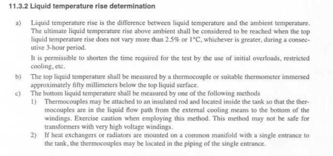
11 ATTACHMENT B Paulette Payne Powell PEPCO Ref: PC D , Hot Resistance Measurements Paulette: Please note my suggestions with respect the above Clause and the defining of the cooling curve. It is my impression that the concerns among many of the WG members is that use of the cooling curve method has become arbitrary with respect to the length of time allowed for the curve and the accuracy of the results so obtained. We should keep in mind that the use of the cooling curve method is a method based on fitting a series of resistance measurements that are changing non-linearly over the time period during which the measurements are taken. The regression curve produced from the best-fit yields the value of the resistance at time zero or the instant of shutdown. Since the analysis is based on a statistical method, the size of the sample or the number of data points has an impact on the accuracy of the curve and the results of the Temperature Rise of the Windings. In my opinion, if one is going to use a cooling curve, then 4 samples are not enough to establish an accurate curve. On the other hand, hundreds of points measured over a long time offer no significant increase in the prediction of the temperatures given the other variables present in the test process. In an effort to attempt to resolve this concern, I submit the following: a) The time from instant of shutdown shall be recorded for each resistance measurement, and b) At least one resistance measurement shall be taken on all windings under test within 4 min after shutdown, and c) A series of at least four resistance measurements shall be made on all windings under test. Each winding of the same phase shall conform to the cooling curve format requiring additional data points. These windings will be used as the basis for correction to time zero for the remaining windings tested, and d) Resistance time measurements in accordance with c) shall be made on all windings, and e) The resistance-time data collected in c) shall be corrected to the instant of shutdown using a resistance-time cooling curve determined by plotting the data on suitable coordinate paper, or by using a computerized curve fitting program. f) The cooling curve format shall consist of a minimum time range from zero to 10 minutes. All resistance measurements taken under 4 minutes will be recorded at no longer than 15-second intervals. All resistance measurements taken after 4 minutes will be recorded at 30-second intervals up to the 10-minute mark. g) The resistance-time data obtained with the cooling curve can be used to determine the correction to shutdown for the same winding of the other phases, provided the first measurement on each of the other phases has been taken within 4 minutes after shutdown. Respectfully submitted, Robert G. Ganser, PE
12 ATTACHMENT C Thermal Calculations - BLUME Method barry Beaster
13 ATTACHMENT C Thermal Calculations - BLUME Method barry Beaster WINDING HV R COLD = Ω Tinf = C T COLD = 30 C Rinf = Ω T AMBIENT = 27.5 C Time (min) R HOT = Blume Fitted 1.50 Ω R t=0 = Ω 2.00 Ω Ω θave = C Ω Ω θrise = C Ω Ω Ω Click to Solve Ω Ω Ω Ω Ω Ω Ω Ω Ω Ω Ω Ω Ω Ω = Intercept = Slope = R = R 2
14 ATTACHMENT C Thermal Calculations - BLUME Method barry Beaster Cooling Curve - Raw Data & Curve Fit HV OHMS Minutes Measured HOT ohms Fitted Values
15 ATTACHMENT D DRAFT PCS REVISIONS TO C Task force for Resistance measurements (Clause 5 of C ) Proposed Changes to Section 5 5. Resistance measurements Resistance measurements are of fundamental importance for the following purposes: a) Calculation of the I 2 R component of conductor losses b) Calculation of winding temperatures at the end of a temperature test c) As a quality control test of the manufacturing process d) As a base for assessing possible damage in the field 5.1 Determination of cold temperature The cold temperature of the winding shall be determined as accurately as possible when measuring the cold resistance. The precautions in through shall be observed General Cold resistance measurements shall not be made on a transformer when it is located in drafts or when it is located in a room in which the liquid or winding temperature is fluctuating rapidly Transformer windings immersed in insulating liquid The temperature of the windings shall be assumed to be the same as the average temperature of the insulating liquid, provided a) The windings have been under insulating liquid with no excitation and with no current in the windings from 3 h to 8 h (depending upon the size of the transformer) for a transformer without pumps and for 1 h for transformer with pumps running before the cold resistance is measured. b) The temperature of the insulating liquid has stabilized, and the difference between top and bottom temperature does not exceed 5 C Transformer windings out of insulating liquid The temperature of the windings shall be recorded as the average of several thermometers or thermocouples inserted between the coils, with care used to see that their measuring points are as nearly as possible in actual contact with the winding conductors. It should not be assumed that the windings are at the same temperature as the surrounding air. 5.2 Conversion of resistance measurements Cold winding resistance measurements are normally converted to a standard reference temperature equal to the rated average winding temperature rise plus 20 C. In addition, it may be necessary to convert the resistance measurements to the temperature at which the impedance loss measurements were made. The conversions are accomplished by Equation (1).
16 ATTACHMENT D DRAFT (1) where Rs is resistance at desired temperature Ts, Rm is measured resistance, Rs is desired reference temperature ( C), Tm is the temperature at which resistance was measured ( C), Tk is C (copper) or 225 C (aluminum). NOTE Τhe value of Tk may be as high as 230 C for alloyed aluminum. 5.3 Resistance measurement methods Voltmeter-ammeter method The voltmeter-ammeter method is the most common method used for transformer winding resistance measurement. It should be employed only if the rated current of the transformer winding is 1 A or more. Resistance measuring systems employing computer controlled digital voltmeters, current measuring shunts, and/or digital ammeters of appropriate accuracy are commonly used for cold resistance measurements and in connection with temperature-rise determinations. To use this method, the following steps should be taken: a) Measurement is made with direct current, and simultaneous readings of current and voltage are taken using the connections of Figure 1. The required resistance is calculated from the readings in accordance with Ohm s Law. Electronic switching power supplies are generally used as voltage sources, however batteries or filtered rectifiers may also be used, especially in those instances where less ripple is desired in the measurement. Automatic recording of periodic voltage and current or resistance readings is recommended so that the pattern of resistance readings can be established. This pattern can then be analyzed to determine the resistance parameters for the test. VOLTAGE SOURCE Figure 1 Connections for voltmeter-ammeter method of resistance measurement b) The voltmeter leads shall be independent of the current leads and shall be connected as closely as possible to the terminals of the winding to be measured. This is to avoid including in the reading the resistances of current-carrying leads and their contacts and of extra lengths of leads. d) Resistance is recommended to be measured at intervals of 5-10 seconds and the readings used shall be after the current and voltage have reached steady-state values. When measuring the cold resistance, preparatory to making a heat run, note the time required for the readings to become constant. That period of time should be allowed to elapse before taking the
17 ATTACHMENT D DRAFT first reading when final winding hot resistance measurements are being made. The residual flux in the core should be made the same for both the cold and hot resistance measurements by saturating the core with dc current prior to the measurement. In general, the winding will exhibit a long dc time constant. To reduce the time required for the current to reach its steady-state value, a noninductive external resistor may be added in series with the dc source. The resistance should be large compared to the inductance of the winding. It will then be necessary to increase the source voltage to compensate for the voltage drop in the series resistor. The time will also be reduced by operating all other transformer windings open-circuited passing a dc current through other windings in either the same polarity as the winding being tested for windings on the same phase or opposite polarity for other phases during these tests. For deltaconnected windings, the time can also be reduced by opening the delta connection. e) It is recommended that at ten or more readings, but a minimum of four readings shall be used for each cold resistance measurement and the average of the resistances calculated from these measurements shall be considered to be the resistance of the circuit. Readings shall be taken with not less than four values of current when deflecting instruments are used. For hot resistance readings, it is recommended that the individual readings are recorded every 5-10 seconds from the point where the inductive effect has subsided for at least 5 minutes (minimum of 30 readings). In no case should less than eight readings be used. The current used shall not exceed 15% of the rated current of the winding whose resistance is to be measured. Larger values may cause inaccuracy by heating the winding and thereby changing its temperature and resistance. c) When making manual resistance measurements: 1) to minimize errors of observation the measuring instruments shall have ranges that will give reasonably large deflection. 2) The polarity of the core magnetization shall be kept constant during all resistance readings. NOTE A reversal in magnetization of the core can change the time constant and result in erroneous readings. 2) To protect the voltmeter from injury by off-scale deflections, the voltmeter should be disconnected from the circuit before switching the current on or off. To protect test personnel from inductive kick, the current should be switched off by a suitably insulated switch. If the drop of voltage is less than 1 V, a potentiometer or millivoltmeter shall be used. 3) Due to inaccuracy of deflecting ammeters and voltmeters, current shunts and digital voltmeters or high-accuracy digital ammeters or other high accuracy instrumentation should be used that meets the requirement of ANSI Std. C Bridge method Bridge methods or other high-accuracy digital instruments should be used in cases where the rated current of the transformer winding to be measured is less than 1 A. NOTE For resistance values of 1Ω or more, a Wheatstone Bridge (or equivalent) is commonly used; for values less than 1Ω, a Kelvin Bridge (or equivalent) is commonly used. Some modern resistance bridges have capability in both ranges. 5.4 Resistance measurement connections and reporting The individual phase or terminal to terminal resistance readings should be reported along with the sum total winding resistance Wye Windings
18 ATTACHMENT D DRAFT For wye windings, the reported resistance measurement may be from terminal to terminal or from terminal to neutral. For the reported total winding resistance, the resistance of the lead from the neutral connection to the neutral bushing may be excluded Delta Windings For delta windings, the reported resistance measurement may be from terminal to terminal with the delta closed or from terminal to terminal with the delta open to obtain the individual phase readings. The reported total winding resistance is the sum of the three phase readings if the delta is open. If the delta is closed, the reported total winding resistance is the sum of the three phase-to-phase readings times Autotransformer Windings For autotransformer series winding resistance, the current shall be circulated between the HV and neutral terminals and the voltage measured between the HV terminal and the LV terminal. For the common winding resistance, the current shall be circulated between the HV and neutral terminals and the voltage measured between the LV and neutral terminals. For the resistance of the lead and in-line windings (if any) between the neutral connection and the LV terminal, the current shall be applied between the HV terminal and the LV terminal and the voltage measured between the LV terminal and the neutral terminal.
19 ATTACHMENT E DRAFT Proposed Change to C /D2 12 April 2002 As we discussed during the Oct meeting of the task force, I have written a proposed change to the wording of e). The issue is that if all of the required hot resistance readings are not completed in the allowed time, the transformer must be heated again before performing another shutdown and continuing the resistance readings. Now the clause states that d) shall be repeated, which implies that the heating should be for 1 hour. If the liquid temperature does not return to the value of the first shutdown, then the measured resistances need to be corrected for the difference in the liquid temperature, adding another step of complexity, and another source for errors. Proposal: Existing wording d) Rated Current Run: Reduce the current in the windings to the rated value for the connection and the loading used. Hold the current constant for one hour. Measure the liquid temperatures and immediately shut down and measure the hot resistances in accordance with e) Repeat step d) for not resistance measurements on additional terminal pairs if needed to meet the time limit criteria of Proposed wording [retain d), revise e)]: d) Rated Current Run: Reduce the current in the windings to the rated value for the connection and the loading used. Hold the current constant for one hour. Measure the liquid temperatures and immediately shut down and measure the hot resistances in accordance with e) If some of the required hot resistance measurements cannot be completed during the time limit criteria of the liquid must be brought back to the original test temperature before making any additional hot resistance measurements on the remaining terminal pairs. Repeat the application of the rated current value for the connection and the loading used and hold until the liquid temperature returns to the value measured in step d). Then proceed to complete the hot resistance measurements in accordance with , repeating this step as needed. Don Platts March 2, 2006
KNOW MORE ABOUT THE TRANSFORMERS. Glossary Transformers
 KNOW MORE ABOUT THE TRANSFORMERS Glossary Transformers Ambient temperature The existing temperature of the atmosphere surrounding a transformer installation. Ampere The practical unit of electric current.
Dennis Marlow has begun work on the first two topics. The others will be addressed in new business.
 9.7 Insulation Life Subcommittee - D.W. Platts The Insulation Life Subcommittee met at 8:00 AM Wednesday, October 17, 2001 in Orlando.. Attendance was 37 members and 72 guests. The minutes of the April
Transformer & Induction M/C
 UNIT- 2 SINGLE-PHASE TRANSFORMERS 1. Draw equivalent circuit of a single phase transformer referring the primary side quantities to secondary and explain? (July/Aug - 2012) (Dec 2012) (June/July 2014)
Back to the Basics Current Transformer (CT) Testing
 Testing") Back to the Basics Current Transformer (CT) Testing As test equipment becomes more sophisticated with better features and accuracy, we risk turning our field personnel into test set operators instead of
Back to the Basics Current Transformer (CT) Testing As test equipment becomes more sophisticated with better features and accuracy, we risk turning our field personnel into test set operators instead of
Regional Technical Seminar TAP CHANGERS
 Regional Technical Seminar TAP CHANGERS SPX Transformer Solutions, Inc. September 4, 2018 De-Energized and Load Tap Changers Jason Varnell Lead Design Engineer jason.varnell@spx.com SPX Transformer Solutions,
PCS Working Group on General Requirements C
 WG Item 82 C57.12.00-2000 Section 7.1.4.4 Stabilizing windings Change Requested by : V. Sankar 5/07/2005 & 10/23/2006 Requested Change : Request to form a task force to discuss the following on buried
A 11/89. Instruction Manual and Experiment Guide for the PASCO scientific Model SF-8616 and 8617 COILS SET. Copyright November 1989 $15.
 Instruction Manual and Experiment Guide for the PASCO scientific Model SF-8616 and 8617 012-03800A 11/89 COILS SET Copyright November 1989 $15.00 How to Use This Manual The best way to learn to use the
Transformer Winding Design. The Design and Performance of Circular Disc, Helical and Layer Windings for Power Transformer Applications
 The Design and Performance of Circular Disc, Helical and Layer Windings for Power Transformer Applications Minnesota Power Systems Conference November 3 5, 2009 Earl Brown Heritage Center University of
Single-Phase Transformation Review
 Single-Phase Transformation Review S T U D E N T M A N U A L March 2, 2005 2 STUDENT TRAINING MANUAL Prerequisites: None Objectives: Given the Construction Standards manual and a formula sheet, you will
Reactor and inductor are names used interchangeably for this circuit device.
 Recommended Design Criteria for Air-Cooled Reactor for Line and Track Circuits Revised 2015 (7 Pages) A. Purpose This Manual Part recommends design criteria for an air-cooled reactor for line and track
Understanding the Value of Electrical Testing for Power Transformers. Charles Sweetser, OMICRON electronics Corp. USA
 Understanding the Value of Electrical Testing for Power Transformers Charles Sweetser, OMICRON electronics Corp. USA Understanding the Value of Electrical Testing for Power Transformers Charles Sweetser,
~=E.i!=h. Pre-certification Transformers
 7 Transformers Section 26 of the electrical code governs the use and installations of transformers. A transformer is a static device used to transfer energy from one alternating current circuit to another.
MAHARASHTRA STATE BOARD OF TECHNICAL EDUCATION
 Important Instructions to examiners: 1) The answers should be examined by key words and not as word-to-word as given in the model answer scheme. 2) The model answer and the answer written by candidate
Optimization of power transformers based on operative service conditions for improved performance
 21, rue d Artois, F-75008 PARIS A2-207 CIGRE 2012 http : //www.cigre.org SUMMARY Optimization of power transformers based on operative service conditions for improved performance A.Prieto, M.Cuesto, P.Pacheco,
ISSN: [IDSTM-18] Impact Factor: 5.164
![ISSN: [IDSTM-18] Impact Factor: 5.164](/thumbs/91/106796217.jpg "ISSN: [IDSTM-18] Impact Factor: 5.164") IJESRT INTERNATIONAL JOURNAL OF ENGINEERING SCIENCES & RESEARCH TECHNOLOGY A REVIEW OF ROUTINE TESTING ON DISTRIBUTION TRANSFORMER Sukhbir Singh 1, Parul Jangra 2, Anoop Bhagat 3, Vipin Saini 4 1 Assistant
IJESRT INTERNATIONAL JOURNAL OF ENGINEERING SCIENCES & RESEARCH TECHNOLOGY A REVIEW OF ROUTINE TESTING ON DISTRIBUTION TRANSFORMER Sukhbir Singh 1, Parul Jangra 2, Anoop Bhagat 3, Vipin Saini 4 1 Assistant
R Distribution Transformers. Mineral Oil-Immersed, Self-Cooled, 60 Hertz Voltages and Connections. Reference Data
 Distribution Transformers Mineral Oil-Immersed, Self-Cooled, 60 Hertz Voltages and Connections R201-90-2 Reference Data CONTENTS POPULAR DlSTRIBUTlON TRANSFORMER AND CIRCUIT VOLTAGES... 1 2400-Volt Systems
PES & IAS NY Chapter And NY LMAG June 23 rd, 2015
 PES & IAS NY Chapter And NY LMAG June 23 rd, 2015 High Temperature Insulation Systems and their use in Mobile Transformers Myron B. Bell, PE mbell@deltastar.com Delta Star, Inc. June 23 rd 2015 Introduction
Group F : Sl. No. - 1) 33/0.403 KV, 100 KVA Station Transformer GUARANTEED & OTHER TECHNICAL PARTICULARS. Table : A
 33/0.403 KV, 100 KVA Station Transformer GUARANTEED & OTHER TECHNICAL PARTICULARS. Table : A") Group F : No. - 1) 33/0.403 KV, 100 KVA Station Transformer GUARANTEED & OTHER TECHNICAL PARTICULARS Table : A No. Description 1. Make & Manufacturer 2. Place of Manufacturer 3. Voltage Ratio 4. Rating
Group F : No. - 1) 33/0.403 KV, 100 KVA Station Transformer GUARANTEED & OTHER TECHNICAL PARTICULARS Table : A No. Description 1. Make & Manufacturer 2. Place of Manufacturer 3. Voltage Ratio 4. Rating
TRANSFORMER THEORY. Mutual Induction
 Transformers Transformers are used extensively for AC power transmissions and for various control and indication circuits. Knowledge of the basic theory of how these components operate is necessary to
Overcurrent and Overload Protection of AC Machines and Power Transformers
 Exercise 2 Overcurrent and Overload Protection of AC Machines and Power Transformers EXERCISE OBJECTIVE When you have completed this exercise, you will understand the relationship between the power rating
Experiment 45. Three-Phase Circuits. G 1. a. Using your Power Supply and AC Voltmeter connect the circuit shown OBJECTIVE
 Experiment 45 Three-Phase Circuits OBJECTIVE To study the relationship between voltage and current in three-phase circuits. To learn how to make delta and wye connections. To calculate the power in three-phase
Temperature Rise Tests
 Temperature Rise Tests Centre for Power Transformer Monitoring, Diagnostics and Life Management (transformerlife) Monash University, Australia Oleg Roizman IntellPower, Australia Valery Davydov Monash
HPS Universal BUCK-BOOST TRANSFORMERS
 BUCK-BOOST TRANSFORMERS Single and Three Phase Potted Buck-Boost Transformers Buck-Boost Applications & Standard Specification... 80 Selecting Buck-Boost Transformers... 81 Single Phase Selection Tables...
OHM S LAW. Ohm s Law The relationship between potential difference (V) across a resistor of resistance (R) and the current (I) passing through it is
 across a resistor of resistance (R) and the current (I) passing through it is") OHM S LAW Objectives: a. To find the unknown resistance of an ohmic resistor b. To investigate the series and parallel combination of resistors c. To investigate the non-ohmic resistors Apparatus Required:
OHM S LAW Objectives: a. To find the unknown resistance of an ohmic resistor b. To investigate the series and parallel combination of resistors c. To investigate the non-ohmic resistors Apparatus Required:
Particulate Control O&M Training. APC/PCUG Conference July 12-16, 2009 The Woodlands, TX
 Particulate Control O&M Training APC/PCUG Conference July 12-16, 2009 The Woodlands, TX WPCA Particulate Training Seminar July 11, 2009 ESP Power Supply Choices Slide No 1 Precipitator Power Supplies Conventional
Technician License Course Chapter 3. Lesson Plan Module 4 Electricity
 Technician License Course Chapter 3 Lesson Plan Module 4 Electricity Fundamentals of Electricity Radios are powered by electricity and radio signals are a form of electrical energy. A basic understanding
(2) New Standard IEEE P (3) Core : (4) Windings :
 New Standard IEEE P (3) Core : (4) Windings :") (d) Electrical characteristics (such as short-circuit withstand, commutating reactance, more number of windings, etc); (e) Longer life expectancy; (f) Energy efficiency; (g) more demanding environment.
(d) Electrical characteristics (such as short-circuit withstand, commutating reactance, more number of windings, etc); (e) Longer life expectancy; (f) Energy efficiency; (g) more demanding environment.
DATA SHEET FOR LIGHTING TRANSFORMER APPD. BY VDV PROJECT NO
 PART - A : SPECIFIC REQUIREMENTS THIS DATA SHEET IS APPLICABLE FOR IN BOILER A CLIMATIC CONDITIONS PACKAGE 1 DESIGN AMBIENT TEMPERATURE 45 C 2 ALTITUDE ( ABOVE MSL ) 6.71 MTRS. 3 RELATIVE HUMIDITY 74 %
Understanding and Extracting Valuable Information from Basic and Advanced Power Transformer Testing Techniques
 Understanding and Extracting Valuable Information from Basic and Advanced Power Transformer Testing Techniques Charles Sweetser, Services Manager, PRIM Engineering, Waltham, Mass. Topics of Discussion
Measurement of Resistance and Potentiometers
 Electrical Measurements International Program Department of Electrical Engineering UNIVERSITAS INDONESIA Measurement of Resistance and Potentiometers Jahroo Renardi Lecturer : Ir. Chairul Hudaya, ST, M.Eng.,
Resistance Temperature Detectors (RTDs)
") Exercise 2-1 Resistance Temperature Detectors (RTDs) EXERCISE OBJECTIVES To explain how resistance temperature detectors (RTDs) operate; To describe the relationship between the temperature and the electrical
Exercise 2-1 Resistance Temperature Detectors (RTDs) EXERCISE OBJECTIVES To explain how resistance temperature detectors (RTDs) operate; To describe the relationship between the temperature and the electrical
148 Electric Machines
 148 Electric Machines 3.1 The emf per turn for a single-phase 2200/220- V, 50-Hz transformer is approximately 12 V. Calculate (a) the number of primary and secondary turns, and (b) the net cross-sectional
SECTION 3 BASIC AUTOMATIC CONTROLS UNIT 12 BASIC ELECTRICITY AND MAGNETISM. Unit Objectives. Unit Objectives 2/29/2012
 SECTION 3 BASIC AUTOMATIC CONTROLS UNIT 12 BASIC ELECTRICITY AND MAGNETISM Unit Objectives Describe the structure of an atom. Identify atoms with a positive charge and atoms with a negative charge. Explain
Rarely used, problems with unbalanced loads.
 THREE-PHASE TRANSFORMERS Transformers used in three-phase systems may consist of a bank of three single-phase transformers or a single three-phase transformer which is wound on a common magnetic core.
Lecture 6 ECEN 4517/5517
 Lecture 6 ECEN 4517/5517 Experiment 4: inverter system Battery 12 VDC HVDC: 120-200 VDC DC-DC converter Isolated flyback DC-AC inverter H-bridge v ac AC load 120 Vrms 60 Hz d d Feedback controller V ref
ELECTRICAL MEASUREMENTS
 R10 Set No: 1 1. a) Derive the expression for torque equation for a moving iron attraction type instrument and comment up on the nature of scale [8] b) Define the terms current sensitivity, voltage sensitivity
Methods of secondary short circuit current control in single phase transformers
 2015; 1(8): 412-417 ISSN Print: 2394-7500 ISSN Online: 2394-5869 Impact Factor: 5.2 IJAR 2015; 1(8): 412-417 www.allresearchjournal.com Received: 17-05-2015 Accepted: 20-06-2015 Parantap Nandi A/2, Building
+ 24V 3.3K - 1.5M. figure 01
 ELECTRICITY ASSESSMENT 35 questions Revised: 08 Jul 2013 1. Which of the wire sizes listed below results in the least voltage drop in a circuit carrying 10 amps: a. 16 AWG b. 14 AWG c. 18 AWG d. 250 kcmil
Webinar Organizers. Ryan Shea. Don Miller. Joe Ryan. Support Specialist. Applications Specialist. Product Manager. Precision Digital Corporation
 Webinar Organizers Joe Ryan Product Manager Precision Digital Corporation Ryan Shea Applications Specialist Precision Digital Corporation Don Miller Support Specialist Precision Digital Corporation Agenda,
DLVP A OPERATOR S MANUAL
 DLVP-50-300-3000A OPERATOR S MANUAL DYNALOAD DIVISION 36 NEWBURGH RD. HACKETTSTOWN, NJ 07840 PHONE (908) 850-5088 FAX (908) 908-0679 TABLE OF CONTENTS INTRODUCTION...3 SPECIFICATIONS...5 MODE SELECTOR
Sine waves by far the most important form of alternating quantity important properties are shown below
 AC DC METERS 1 Sine waves by far the most important form of alternating quantity important properties are shown below 2 Average value of a sine wave average value over one (or more) cycles is clearly zero
Electrical Description
 History of this Document Rev. no.: Date: Description of change 0 First edition 2 2003-10-08 Section 3: The rated power of the transformer can be increased by 40% if they are equipped with 6 fans for forced
Tertiary Winding Design in wye-wye Connected Transformers Restricted Siemens Energy 2013 All rights reserved.
 Pomona, CA, May 24 & 25, 2016 Tertiary Winding Design in wye-wye Connected Transformers Scope of Presentation > Tertiary vs. Stabilizing Winding? Tertiary vs. Stabilizing Winding? Need for Stabilizing
Electric Current & DC Circuits
 Electric Current & DC Circuits PSI AP Physics B Name Multiple-Choice 1. The length of an aluminum wire is quadrupled and the radius is doubled. By which factor does the resistance change? (A) 2 (B) 4 (C)
Power Factor Insulation Diagnosis: Demystifying Standard Practices
 Power Factor Insulation Diagnosis: Demystifying Standard Practices Dinesh Chhajer, PE 4271 Bronze Way, Dallas Tx Phone: (214) 330 3238 Email: dinesh.chhajer@megger.com ABSTRACT Power Factor (PF) testing
Generator Advanced Concepts
 Generator Advanced Concepts Common Topics, The Practical Side Machine Output Voltage Equation Pitch Harmonics Circulating Currents when Paralleling Reactances and Time Constants Three Generator Curves
Short-Circuit Current Calculations
 Basic Point-to-Point Calculation Procedure Step. Determine the transformer full load amps (F.L.A.) from either the nameplate, the following formulas or Table : Multiplier = 00 *% Z transformer Step 2.
CONSULTANT PROCEDURES & DESIGN GUIDELINES Liquid-Filled Utility Transformers UNIVERSITY OF MISSOURI
 GENERAL: The scope of this document is to provide instruction for the installation and testing of Medium Voltage, 3 Phase, Pad Mounted Transformers installed at the University of Missouri. Preferred transformers
1. Explain in detail the constructional details and working of DC motor.
 DHANALAKSHMI SRINIVASAN INSTITUTE OF RESEARCH AND TECHNOLOGY, PERAMBALUR DEPT OF ECE EC6352-ELECTRICAL ENGINEERING AND INSTRUMENTATION UNIT 1 PART B 1. Explain in detail the constructional details and
AC/DC Power Supply Series APPLICATION NOTE
 -175 AC/DC Power Supply Series APPLICATION NOTE NV175 Application notes 3.4.doc Document Number 69493 Page 1 of 16 1. INPUT...3 AC INPUT LINE REQUIREMENTS... 3 2. DC OUTPUT...3 OUTPUT VOLTAGES... 3 REMOTE
Chapters 34: Ohm s Law
 Text: Chapter 34 Think and Explain: 1-3, 6-8, 10 Think and Solve: 1-6 Chapters 34: Ohm s Law Vocabulary: Ohm s Law, resistance, resistivity, superconductor, current, amps, volts, ohms, kw-h, AC, DC Equations:
AUTOMATION OF THE TEMPERATURE ELEVATION TEST IN TRANSFORMERS WITH INSULATING OIL
 AUTOMATION OF THE TEMPERATURE ELEVATION TEST IN TRANSFORMERS WITH INSULATING OIL José Manuel Esteves Vicente Ângelo José Junqueira Rezek Antônio Tadeu Lyrio de Almeida UNIFEI/IEE/DET Federal University
The measurement of winding resistance is useful in detecting a number of types of fault in a transformer. Malfunctioning tap changer mechanisms
 Why Measure Winding Resistance? The measurement of winding resistance is useful in detecting a number of types of fault in a transformer. Malfunctioning tap changer mechanisms Partial or dead short-circuited
Module 1, Lesson 2 Introduction to electricity. Student. 45 minutes
 Module 1, Lesson 2 Introduction to electricity 45 minutes Student Purpose of this lesson Explanations of fundamental quantities of electrical circuits, including voltage, current and resistance. Use a
Chapter 6. WIRING SYSTEMS Safe Electrical Design
 Chapter 6 WIRING SYSTEMS Safe Electrical Design Topic 6-3 CABLE SELECTION BASED ON CURRENT CARRYING CAPACITY REQUIREMENTS INSTALLATION CONDITIONS Current carrying capacity (CCC) is the maximum continuous
Ohm s Law and Electrical Circuits
 Ohm s Law and Electrical Circuits INTRODUCTION In this experiment, you will measure the current-voltage characteristics of a resistor and check to see if the resistor satisfies Ohm s law. In the process
15. the power factor of an a.c circuit is.5 what will be the phase difference between voltage and current in this
 1 1. In a series LCR circuit the voltage across inductor, a capacitor and a resistor are 30 V, 30 V and 60 V respectively. What is the phase difference between applied voltage and current in the circuit?
SPECIFICATION FOR STEP UP TRANSFORMER 0.415/11Kv and (630KVA & 1000KVA)
") SPECIFICATION FOR STEP UP TRANSFORMER 0.415/11Kv and (630KVA & 1000KVA) 0.415/33kV DESIGN AND CONSTRUCTION General 1. The transformer shall be three phase, oil immersed type, air cooled, core type, outdoor
SPECIFICATION FOR STEP UP TRANSFORMER 0.415/11Kv and (630KVA & 1000KVA) 0.415/33kV DESIGN AND CONSTRUCTION General 1. The transformer shall be three phase, oil immersed type, air cooled, core type, outdoor
MODEL INFORMATION. Model AWRMS TM 200. Automated Winding Resistance Measurement System
 Model AWRMS TM 200 Automated Winding Resistance Measurement System Currents up to 200A for performing Winding Resistance and Heat Run Tests. Heavy Duty Protection Circuit. Accuracy with Four Wire Measurements
Chapter 20 Electric Circuits
 Chapter 20 Electric Circuits 1 20.1 Electromotive Force and Current In an electric circuit, an energy source and an energy consuming device are connected by conducting wires through which electric charges
WESTERN UNDERGROUND COMMITTEE GUIDE 2.6 (2.6/00/0868)
") WESTERN UNDERGROUND COMMITTEE GUIDE 2.6 (2.6/00/0868) THREE-PHASE SUBSURFACE UNDERGROUND COMMERCIAL DISTRIBUTION (UCD) TRANSFORMER NOTE: This "Guide" summarizes the opinions, recommendations, and practices
WESTERN UNDERGROUND COMMITTEE GUIDE 2.6 (2.6/00/0868) THREE-PHASE SUBSURFACE UNDERGROUND COMMERCIAL DISTRIBUTION (UCD) TRANSFORMER NOTE: This "Guide" summarizes the opinions, recommendations, and practices
APPLICATION NOTE. Wide Range of Resistance Measurement Solutions from μω to PΩ
 APPLICATION NOTE Wide Range of Resistance Measurement Solutions from μω to PΩ Introduction Resistance measurement is one of the fundamental characterizations of materials, electronic devices, and circuits.
Question Bank SENSORS AND INSTRUMENTATION [EE-305/405]
![Question Bank SENSORS AND INSTRUMENTATION [EE-305/405]](/thumbs/95/124646158.jpg "Question Bank SENSORS AND INSTRUMENTATION [EE-305/405]") UNIT-1 1. Discuss liquid in glass thermometers? 2. Write a short note on strain gauges. 3. Mention the various temperature scales and relation between them. 4. An experiment is conducted to calibrate a
UNIT-1 1. Discuss liquid in glass thermometers? 2. Write a short note on strain gauges. 3. Mention the various temperature scales and relation between them. 4. An experiment is conducted to calibrate a
TesTIng of Power. Transformers are the largest, most. feature. By brandon dupuis
 feature By brandon dupuis An Introduction to Electrical diagnostic TesTIng of Power Transformers 38 Transformers are the largest, most expensive, and highly critical components of most utility substations.
ON-LINE STATOR TEMPERATURE MONITOR FOR SINGLE-PHASE INDUCTION MOTORS
 ONLINE STATOR TEMPERATURE MONITOR FOR SINGLEPHASE INDUCTION MOTORS W.L. Soong, A. Harris and C.H. Fong Adelaide University A. Kennewell, J. Botiuk and D. Gray ITS, Adelaide Abstract All electrical appliances
Resistance and Ohm s law
 Resistance and Ohm s law Objectives Characterize materials as conductors or insulators based on their electrical properties. State and apply Ohm s law to calculate current, voltage or resistance in an
INPUT: 110/220VAC. Parallel Input Series Input Parallel Output Series Output (W/CT)
") Linear power supply design: To make a simple linear power supply, use a transformer to step down the 120VAC to a lower voltage. Next, send the low voltage AC through a rectifier to make it DC and use a
Linear power supply design: To make a simple linear power supply, use a transformer to step down the 120VAC to a lower voltage. Next, send the low voltage AC through a rectifier to make it DC and use a
Transformer Factory Testing
 Transformer Factory Testing John J. Foschia Test Engineer John.Foschia@spx.com September 2018 Reasons for Testing Compliance with user specifications Assessment of quality and reliability Verification
1 V = IR P = IV R eq. 1 R i. = R i. = R eq. V = Energy Q. I = Q t
 Chapters 34 & 35: Electric Circuits NAME: Text: Chapter 34 Chapter 35 Think and Explain: 1-3, 6-8, 10 Think and Explain: 1-10 Think and Solve: 1-6 Think and Solve: 1-4 Vocabulary: Ohm s Law, resistance,
AC Resistance Thermometry Bridges and their Advantages By Peter Andrews
 AC Resistance Thermometry Bridges and their Advantages By Peter Andrews AC Resistance Thermometry Bridges and their advantages What is at the heart of the AC bridge concept? And what makes it so special?
Transformers. gpmacademics.weebly.com
 TRANSFORMERS Syllabus: Principles of operation, Constructional Details, Losses and efficiency, Regulation of Transformer, Testing: OC & SC test. TRANSFORMER: It is a static device which transfers electric
Regional Technical Seminar SHORT CIRCUIT FORCES
 Regional Technical Seminar SHORT CIRCUIT FORCES Short Circuit Forces Wallace Exum Electrical Design Engineer wallace.exum@spx.com Agenda 1. What is Short Circuit 2. Types of Faults 3. How to Calculate
Glossary 78 LIFETIME LIMITED WARRANTY. GREENLEE Phone: (International)
") A AC alternating current, or current that reverses direction at regular rate. When graphed, alternating current can appear as a series of curves, squares, or triangles. The shape of the graph is referred
A AC alternating current, or current that reverses direction at regular rate. When graphed, alternating current can appear as a series of curves, squares, or triangles. The shape of the graph is referred
McPherson Voltage Regulators 4501 NW 27 Ave Miami FL
 McPherson Voltage Regulators 4501 NW 27 Ave Miami FL 33142 305-634-1511 To avoid of possible personal injury or equipment damage read and understand this manual before installation. (A.V.R) 208 / 380 /
νµθωερτψυιοπασδφγηϕκλζξχϖβνµθωερτ ψυιοπασδφγηϕκλζξχϖβνµθωερτψυιοπα σδφγηϕκλζξχϖβνµθωερτψυιοπασδφγηϕκ χϖβνµθωερτψυιοπασδφγηϕκλζξχϖβνµθ
 θωερτψυιοπασδφγηϕκλζξχϖβνµθωερτψ υιοπασδφγηϕκλζξχϖβνµθωερτψυιοπασδ φγηϕκλζξχϖβνµθωερτψυιοπασδφγηϕκλζ ξχϖβνµθωερτψυιοπασδφγηϕκλζξχϖβνµ Physics θωερτψυιοπασδφγηϕκλζξχϖβνµθωερτψ Current and Electricity υιοπασδφγηϕκτψυιοπασδφγηϕκλζξχϖβν
Power Transformers Basics
 Power Transformers Basics Transformer Basic Objective Introduce Basic Transformer Theory as it Relates to Diagnostics Provide a Better Understanding of the Diagnostic Test Environment Identify Important
Electronic Measurements & Instrumentation. 1. Draw the Maxwell s Bridge Circuit and derives the expression for the unknown element at balance?
 UNIT -6 1. Draw the Maxwell s Bridge Circuit and derives the expression for the unknown element at balance? Ans: Maxwell's bridge, shown in Fig. 1.1, measures an unknown inductance in of standard arm offers
Three Phase Transformers
 EE/CME 392 Laboratory 6-1 Three Phase Transformers Safety The voltages used in this experiment are lethal. Assemble or modify a circuit only with the breakers off. Do not apply power until the wiring has
Howard Smart Transformer Specification Guide
 Howard Smart Transformer Specification Guide General Requirements Overhead pole-type smart distribution transformers shall be single phase, 60 Hz, mineral-oil filled and self-cooled and shall conform as
Automatic Transformer Winding Analyser
 2293 Automatic Transformer Winding Analyser The 2293 is an automatic winding analyser, optimized for three phase power and distribution transformer measurements. It uniquely combines winding resistance
Half-wave Rectifier AC Meters
 Note-4 1 Half-wave Rectifier AC Meters Disadvantages: 1. In negative half-cycle, reverse current flows through the circuit reduces average value of current meter reads lower than actual. 2. High peak inverse
POWER TRANSFORMER SPECIFICATION, DESIGN, QUALITY CONTROL AND TESTING 18 MARCH 2009
 POWER TRANSFORMER SPECIFICATION, DESIGN, QUALITY CONTROL AND TESTING 18 MARCH 2009 Nkosinathi Buthelezi Senior Consultant: Power Transformers and Reactors Presentation Content Standardization of Power
ECG 741 Power Distribution Transformers. Y. Baghzouz Spring 2014
 ECG 741 Power Distribution Transformers Y. Baghzouz Spring 2014 Preliminary Considerations A transformer is a device that converts one AC voltage to another AC voltage at the same frequency. The windings
TABLE 1 - SPECIFICATIONS PARAMETER CSM2512 CSM3637
 Bulk Metal Technology High Precision, Current Sensing, Power Surface Mount, Metal Strip Resistor with Resistance Value from 1 mω, Rated Power up to 3 W and TCR to ± 15 ppm/ C Maximum No minimum order quantity
Practical Tricks with Transformers. Larry Weinstein K0NA
 Practical Tricks with Transformers Larry Weinstein K0NA Practical Tricks with Transformers Quick review of inductance and magnetics Switching inductive loads How many voltages can we get out of a $10 Home
FIELD ELECTRICAL TESTING SPX TRANSFORMER SOLUTIONS, INC.
 Regional Technical Seminar FIELD ELECTRICAL TESTING SPX TRANSFORMER SOLUTIONS, INC. Field Electrical Testing Applications Key Purposes of Field Electrical Testing: Receiving inspection Acceptance testing/commissioning
1A Ultra Low Dropout Voltage Regulator with Multi-Functions
 1A Ultra Low Dropout Voltage Regulator with Multi-Functions DESCRIPTION The TS39104 are 1A ultra low dropout linear voltage regulators that provide low voltage, high current output from an extremely small
GE Ventilated Dry-Type Transformers. Secondary Substation Transformers - 5 and 15kV Class
 GE Ventilated Dry-Type Transformers Secondary Substation Transformers - 5 and 15kV Class GE ventilated dry-type transformers are designed for indoor or outdoor applications in schools, hospitals, industrial
MGM Transformer. Vacuum Pressure Impregnated (VPI) Dry-Type Substation Transformer Specification Guide
 Dry-Type Substation Transformer Specification Guide") MGM Transformer Vacuum Pressure Impregnated (VPI) Dry-Type Substation Transformer Specification Guide MGM Transformer Company 5701 Smithway Street Commerce, CA 90040 www.mgmtransformer.com Phone: 323.726.0888
MGM Transformer Vacuum Pressure Impregnated (VPI) Dry-Type Substation Transformer Specification Guide MGM Transformer Company 5701 Smithway Street Commerce, CA 90040 www.mgmtransformer.com Phone: 323.726.0888
Technical Information General Purpose Relays
 Glossary CONTACTS Contact Form The contact mechanism of the Relay. Number of Contact Poles The number of contact circuits. Rated Load The rated load of the contact of the Relay, which determines the characteristic
MAHARASHTRA STATE BOARD OF TECHNICAL EDUCATION
 Important Instructions to examiners: 1) The answers should be examined by key words and not as word-to-word as given in the model answer scheme. 2) The model answer and the answer written by candidate
Beyond the Knee Point: A Practical Guide to CT Saturation
 Beyond the Knee Point: A Practical Guide to CT Saturation Ariana Hargrave, Michael J. Thompson, and Brad Heilman, Schweitzer Engineering Laboratories, Inc. Abstract Current transformer (CT) saturation,
Experiment 6. Electromagnetic Induction and transformers
 Experiment 6. Electromagnetic Induction and transformers 1. Purpose Confirm the principle of electromagnetic induction and transformers. 2. Principle The PASCO scientific SF-8616 Basic Coils Set and SF-8617
Training Fees 3,300$ per participant including Materials/Handouts, Tea/Coffee Refreshments & International Buffet Lunch.
 Training Title POWER TRANSFORMERS Training Duration 5 days Training Venue and Dates Power transformers 5 20-24 May $3,300 Abu Dhabi In any of the 5 star hotel. The exact venue will be informed soon. Training
UNIVERSITY OF TECHNOLOGY By: Fadhil A. Hasan ELECTRICAL MACHINES
 UNIVERSITY OF TECHNOLOGY DEPARTMENT OF ELECTRICAL ENGINEERING Year: Second 2016-2017 By: Fadhil A. Hasan ELECTRICAL MACHINES І Module-II: AC Transformers o Single phase transformers o Three-phase transformers
Winding Temperature Measurement in a 154 kv Transformer Filled with Natural Ester Fluid
 J Electr Eng Technol Vol. 8, No. 1: 156-162, 2013 http://dx.doi.org/10.5370/jeet.2013.8.1.156 ISSN(Print) 1975-0102 ISSN(Online) 2093-7423 Winding Temperature Measurement in a 154 kv Transformer Filled
Downloaded from
 Question 1: What does an electric circuit mean? An electric circuit consists of electric devices, switching devices, source of electricity, etc. that are connected by conducting wires. Question 2: Define
Transformer Protection Principles
 Transformer Protection Principles 1. Introduction Transformers are a critical and expensive component of the power system. Due to the long lead time for repair of and replacement of transformers, a major
Exercise 10. Transformers EXERCISE OBJECTIVE DISCUSSION OUTLINE DISCUSSION. Introduction to transformers
 Exercise 10 Transformers EXERCISE OBJECTIVE When you have completed this exercise, you will be familiar with the basic operating principles of transformers, as well as with the different ratios of transformers:
IDAHO PURPA GENERATOR INTERCONNECTION REQUEST (Application Form)
") IDAHO PURPA GENERATOR INTERCONNECTION REQUEST (Application Form) Transmission Provider: IDAHO POWER COMPANY Designated Contact Person: Jeremiah Creason Address: 1221 W. Idaho Street, Boise ID 83702 Telephone
IDAHO PURPA GENERATOR INTERCONNECTION REQUEST (Application Form) Transmission Provider: IDAHO POWER COMPANY Designated Contact Person: Jeremiah Creason Address: 1221 W. Idaho Street, Boise ID 83702 Telephone