R2009/R3016 User Manual
|
|
|
- Tracy Byrd
- 5 years ago
- Views:
Transcription

1 R2009/R3016 User Manual ENGLISH navico-commercial.com
2
3 Preface Disclaimer As Navico is continuously improving this product, we retain the right to make changes to the product at any time which may not be reflected in this version of the manual. Please contact your nearest distributor if you require any further assistance. It is the owner s sole responsibility to install and use the equipment in a manner that will not cause accidents, personal injury or property damage. The user of this product is solely responsible for observing maritime safety practices. NAVICO HOLDING AS AND ITS SUBSIDIARIES, BRANCHES AND AFFILIATES DISCLAIM ALL LIABILITY FOR ANY USE OF THIS PRODUCT IN A WAY THAT MAY CAUSE ACCIDENTS, DAMAGE OR THAT MAY VIOLATE THE LAW. This manual represents the product as at the time of printing. Navico Holding AS and its subsidiaries, branches and affiliates reserve the right to make changes to specifications without notice. Governing Language This statement, any instruction manuals, user guides and other information relating to the product (Documentation) may be translated to, or has been translated from, another language (Translation). In the event of any conflict between any Translation of the Documentation, the English language version of the Documentation will be the official version of the Documentation. Copyright Copyright 2016 Navico Holding AS. Warranty The warranty card is supplied as a separate document. In case of any queries, refer to the brand website of your display or system: navicocommercial.com/. Regulatory statements This equipment is intended for use in international waters as well as coastal sea areas administrated by member states pursuant to international conventions. The R2009 and R3016 Control units comply with: EMC directive 2014/30/EU Refer to the product website for the latest information about product compliance. The relevant Declaration of Conformity is available on the product's section on the following website: navico-commercial.com/. About this manual This manual is a reference guide for operating, installing and configuring the software for the R2009 and R3016 Control units. Ú Note: This manual does not cover installation of the various antennas that can be used in these radar systems. In addition to this manual the following documents are available for the R2009 and R3016 Control units: R2009/R3016 Quick Guide ( n) R2009 Control unit Mounting template ( n) R3016 Control unit Mounting template ( n) The last digit in the part numbers is the document's revision code. The latest version of all documents can be downloaded from the product website on navico-commercial.com/. Ú Note: Separate manuals are delivered for the R U/6X type approved radar system. Preface R2009/R3016 User manual 3
4 Important text conventions Important text that requires special attention from the reader is emphasized as follows: Ú Note: Used to draw the reader s attention to a comment or some important information. Warning: Used when it is necessary to warn personnel that they should proceed carefully to prevent risk of injury and/or damage to equipment/ personnel. Intended audience This manual is written for system operators and installers. It assumes that the user has basic knowledge of radars, navigation, nautical terminology and practices. Viewing the manual on the screen The PDF viewer included in the unit makes it possible to read the manuals and other PDF files on the screen. The manuals can be read from a card inserted in the card reader or copied to the unit s internal memory. The PDF file is opened from the File manager, refer to "Files" on page 48. Manuals can be downloaded at: navico-commercial.com/ Use the keys to maneuver in the PDF file as described below: Scroll pages Use the rotary knob. Zoom in/out Use the + and - keys. Maneuver on a page that is larger than the display area Use the arrow keys. Exit the PDF viewer Use the EXIT key Safety precautions Safety precautions described in this section are applicable to the radar system. They are general safety precautions that are not related to any specific procedure, and they might therefore not appear elsewhere in this manual. They are recommended precautions that personnel must understand and apply during operation and maintenance of the system. You are obliged to read these operating instructions prior to operation, and to adhere to the operating instructions in order to prevent possible danger. Prevention of danger includes that operator personnel are trained and authorized for safe operation of the equipment. We assume no liability for damage due to improper operation which could have been prevented. The system must only be operated by persons who have passed the relevant mandatory training on the respective systems and applications. Only reading these operating instructions cannot replace such training. Persons authorized to operate, maintain and troubleshoot the system are instructed and trained by Simrad. Persons operating or servicing this radar system must be familiar with the general safety regulations and specific safety systems, and they must have passed all required training. They must have read the relevant operating instructions and manuals before starting to work. Have these operating instructions always at hand on all relevant locations, and ensure that copies are available to all operators. Operating personnel must at all times follow all safety regulations. During normal operation, the unit can be quickly disconnected from the main power line by turning OFF the relevant circuit breaker located on the electric switchboard. Do not replace components or make adjustments inside the unit when the voltage supply is turned ON. Always remove power and discharge to ground a circuit before touching it. Under no circumstances should any person initiate servicing or repairing the unit except in the presence of a qualified person. 4 Preface R2009/R3016 User manual
5 Ensure unobstructed access to all operator panels, controls, and relevant switchgear cabinets in order to enable instant response to alarms. Whenever it is necessary to disconnect the waveguide from a radar transmitter for maintenance purpose, the transmitter output should be terminated with a matched load. If this is not possible, care should be taken. Do not stand in front of an open-ended waveguide from which power is being radiated. Ú Note: Main power is always present on the terminal board unless the main break from the power distribution panel of the vessel is turned off. Warning: Never look down a waveguide from which power is being radiated! Warnings High voltage Radar equipment includes high voltage that can cause injury or loss of life. Danger exists only when the units are opened, exposing internal circuits, as when servicing the equipment. This radar has been carefully designed to protect personnel from possible injury from high voltages. Although every effort has been made to eliminate danger to personnel, no responsibility is accepted for any injury or loss of life suffered in connection with this equipment. Trademarks Navico is a registered trademark of Navico. Simrad is used by license from Kongsberg. NMEA and NMEA 2000 are registered trademarks of the National Marine Electronics Association. SimNet is a registered trademark of Navico. SD and microsd are trademarks or registered trademarks of SD-3C, LLC in the United States, other countries or both. HDMI and HDMI, the HDMI Logo, and High-Definition Multimedia Interface are trademarks or registered trademarks of HDMI Licensing LLC in the United States and other countries. Preface R2009/R3016 User manual 5
6 Contents 9 Introduction 9 R2009 and R3016 Radar Control units 9 O2000 Controller 9 System diagrams 11 The user interface 11 Front panel and keys 12 Main panel 13 PPI symbols 13 Picture freeze indicator 14 Softkeys 14 The menu system 15 Measurements units 15 Radar palettes 16 On-screen keyboard 16 Screen capture 17 Basic operation 17 Turning the system on and off 17 Adjusting display brightness 17 Selecting radar source 17 Switching between Transmit and Standby mode 17 Adjusting the radar range 17 Using the cursor 18 Target tracking 18 Selecting speed source and stabilization mode 19 Adjusting the radar image 19 Gain 19 Rain anti-clutter 19 Sea anti-clutter 20 Tune 21 Radar view options 21 Target trails and past position 21 Radar orientation 21 Radar motion mode 22 Offsetting the PPI center 22 Vectors 23 Cursor bearings 23 Applying default control settings 24 Target tracking 24 Managing targets 24 Defining dangerous vessels 24 Radar targets 27 AIS targets 28 Displaying target information 30 Navigation tools 30 Guard zones 30 EBL/VRM markers 32 Measuring range and bearing 34 Advanced radar options 34 Use modes 6 Contents R2009/R3016 User manual
7 34 Radar threshold 34 Rejecting radar interference 35 Noise rejection 35 Target boost 35 Target expansion 35 Target separation 35 Fast scan 36 Installation 36 Box contents 36 Mounting location 37 Viewing angle 38 U-bracket mounting 38 Panel mounting 39 Wiring 39 Guidelines 39 Rear connections 40 Ethernet connector 40 Power connection 41 External alarm 42 NMEA 2000 backbone 44 NMEA 0183 device connection 46 Connect an external monitor 47 Software setup 47 System settings 48 Network settings 52 Radar settings 57 Own ship 58 Simulator 58 Demo mode 58 Simulator source files 58 Advanced simulator settings 60 Maintenance 60 Preventive maintenance 60 Cleaning the display unit 60 Cleaning the media port door 60 Checking the keys 60 Checking the connectors 60 NMEA Data logging 61 Software upgrades 61 Backing up your system data 62 The alert system 62 Type of alerts 62 Alert notifications 63 Acknowledging alerts 63 The Alerts dialog 64 Alphabetic alarm listing 65 Operating modes fallback 66 Terms and abbreviations 70 Spare parts and accessories 70 R2009 Options and accessories Contents R2009/R3016 User manual 7
8 70 R2009 Spare parts and service packs 70 R3016 Options and accessories 71 R3016 Spare parts and service packs 72 Technical specifications 72 Overview 72 Display 72 Technical/environmental 73 Power 73 Compass safe distance 74 Menu tree 75 Dimensional drawings 75 R2009 Control unit 75 R3016 Control unit 8 Contents R2009/R3016 User manual
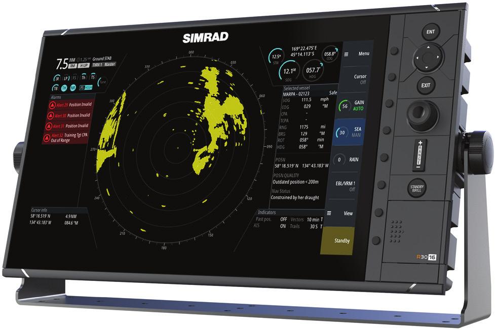
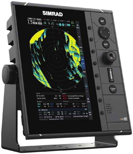
9 ABC DEF GHI JKL MNO PQRS TUV WXYZ 1 Introduction R2009 and R3016 Radar Control units The R2009 and R3016 are dedicated Radar Control units with integrated 9-inch portrait and 16-inch widescreen display. The units are compatible with a range of Simrad radar solutions, including Halo Pulse Compression, Broadband 3G /4G, and HD Digital radars. The R2009 is fitted with a high brightness screen and is suited for both pilot house and outside installation. The R3016 is suited to pilot house installation only. Ú Note: The R3016 is also used as control unit in the Category 3 type approved R U/6X Radar systems. Separate manuals are delivered for the R U/6X Radar systems. O2000 Controller The optional O2000 Controller can be used to remotely operate up to 4 radar control units. Separate documentation is delivered for the O2000 Controller. STANDBY C System diagrams The images on the next pages shows examples of typical radar installations with the R2009 and R3016 control units. The first illustration is an example of a basic system installation with one control unit, a radar antenna, a heading sensor and a position sensor The second illustration shows a complex radar installation. In addition to the R3016 Control unit and sensors this has the optional O2000 Remote controller and two radar antennas connected. It is also indicated how the system can be combined with an MFD and with a second monitor mirroring the radar signal. Halo R3016 (or R2009) ETHERNET HDMI NMEA2000 POWER NMEA0183 NMEA0183 Heading and position sensors RI-12 T T + _ 12 / 24 V DC + _ 12 V DC Introduction R2009/R3016 User manual 9
10 Introduction R2009/R3016 User manual _ 12 / 24 V DC + RI-12 RI-10 4G NEP-2 NETWORK NETWORK Halo NETWORK HDMI-1 _ NETWORK NETWORK ETHERNET HDMI USB T NMEA2000 POWER NMEA0183 NMEA0183 T VIDEO-3 VIDEO-4 NMEA2K SERIAL 12 / 24 V DC + DVI-2 POWER MO Monitor (repeater from 3016 only) R3016 (or R2009) POWER 10 _ ETHERNET ETHERNET HDMI NMEA 2000 VIDEO POWER SONAR STRUCTURE Heading and position sensors NSS evo2 12 V DC + O2000
11 2 The user interface Front panel and keys Softkeys Press a key once to access options for the corresponding function. 2 Enter (ENT) key With no menu or cursor not active: no function. With cursor active on PPI: press to acquire a selected target, press and hold to display options for managing targets. Menu and pop-up operation: press to select an option or activate/deactivate an option. 3 Arrow keys With no menu active: press to move the cursor on the radar PPI. Menu operation: press to move through menu items and to adjust a value. 4 Exit (EXIT) key With no menu or cursor not active: no function. With cursor active on PPI: press to remove cursor. Menu operation: press to return to previous menu level or to exit a dialog. 5 Rotary knob With no menu active: behavior depending on operational mode. Menu operation: rotate to scroll through menu items and to adjust values, press to select or to save settings. 6 Range (RANGE) key Press the + or the - indication to increase or decrease the radar range. 7 Standby/Brilliance (STANDBY/BRILL) key Press once to display the Brilliance/Standby pop-up, press again to toggle between Standby and Transmit mode. Press and hold to switch the radar system on/off. 8 Card reader door 9 SD card reader The user interface R2009/R3016 User manual 11
 Radar video area where all tracking and navigation options are performed.")

12 Main panel The main panel is divided into predefined areas as shown in the figure below. R2009 R Plan Position Indicator (PPI) Radar video area where all tracking and navigation options are performed. 2 Own ship information Stabilization mode indicator, picture freeze indicator and gauges showing primary and secondary sensors. 3 Target panel Detailed information about selected targets and AIS targets. 4 Softkey bar Reference for softkey functions. 5 Target indicators Overview of target indicator settings. 6 Markers Details for active VRM and EBL markers. 12 The user interface R2009/R3016 User manual


13 7 Cursor information Range and bearing from the vessel to the cursor position. Also including position information if a position source is available. 8 Alerts panel List of all active alerts. 9 Signal indicators Gauges for signal processing and indicators for radar functions. 10 System information Range, mode and pulse details. PPI symbols Range rings and heading line symbols can be turned on and off individually from the PPI symbols sub menu. The Overlay graphic off menu option turns off all graphics overlaid on the radar PPI, showing only the video signal. Ú Note: The Heading line off and Overlay graphic off menu options are mono stable, meaning that you need to press and hold the ENT key or the right arrow key to temporarily remove the relevant symbols from the panel. The graphics are invisible as long as the key is pressed, and will turn on again when the key is released. Picture freeze indicator The Own ship information area includes a picture freeze indicator (A). The small dot blinks at an interval of 1 second to show that the screen is alive and that information from sensors are updated. If the picture freezes the R3016 Control unit needs to be restarted. The user interface R2009/R3016 User manual 13


14 Softkeys The softkeys are always accessible, and the softkey bar is always displayed on the radar panel. When a softkey is pressed, the function for the selected softkey becomes available. The arrow keys, the rotary knob and the ENT key have different functions depending on which softkey is selected. More details about the softkey functionality are available in the separate section describing the functions later in this manual. Softkey pop-ups If you press the GAIN, SEA and EBL/VRM softkey twice, their corresponding pop-up is displayed. If a pop-up has more than one option, you select the options by using the arrow keys. You remove the pop-up and revert to the softkey's main function by re-pressing the softkey, by pressing another softkey or by pressing the EXIT key. The menu system The menu system consists of the main menu with sub menus. The main menu gives access to the Settings dialogs. If a menu is inactive for 10 seconds the menu will automatically close. Main menu and sub menus You access the Main menu by pressing the Menu softkey. Use the up and down arrow keys or turn the rotary knob to move up and down in a menu Press the ENT key, the right arrow key or the rotary knob to access a sub menu, to toggle options and to confirm a selection Press the EXIT key or the left arrow key to return to previous menu level and then exit the menu system A selected menu item is indicated with a blue background. If a sub-menu is available this is indicated with a right arrow after the text. Selected menu item Sub-menu indication Settings dialogs The various Settings dialogs provide access to system settings and for vessel specific settings. You access the Settings dialogs from the Main menu. 14 The user interface R2009/R3016 User manual


15 Use the up and down arrow keys or turn the rotary knob to move up and down in a Settings dialog Press the ENT key, the right arrow key or the rotary knob to access the Settings details and to confirm a selection Press the EXIT key to close a dialog There is no time-out for the Settings dialogs. A dialog remains open until it is manually closed. Measurements units You can change the measurement units from the Units Settings dialog. Ú Note: Measurements units can only be changed when the connected antenna is in standby. Radar palettes Different palettes are available for the radar video and for the target trails. You select the palettes from the Radar Settings dialog. The user interface R2009/R3016 User manual 15

16 On-screen keyboard A numeric or alphanumeric virtual keyboard is displayed when required to enter user information in dialogs. Select a virtual key by using the arrow keys followed by the ENT key to confirm the selection Complete the entry and close the dialog by selecting the Enter virtual key You remove the virtual keyboard without entering information by pressing the EXIT key. Screen capture Simultaneously press the ENT and Power/Brilliance keys to take a screen capture. Screen captures are saved to internal memory. To view files, refer to "Files" on page The user interface R2009/R3016 User manual


17 3 Basic operation Turning the system on and off The system is switched ON by pressing the STANDBY/BRILL key on the control unit. Press and hold the STANDBY/BRILL key for 5 seconds to turn the control unit and the radar antenna off Ú Note: The R2009 Control unit can be wired and configured for power control. If the unit is configured as a power slave, the unit will turn on and off when the power master is turned on and off. Refer to "Power Control" on page 48. Adjusting display brightness At first start-up the display brilliance is set to 100%. When the unit is restarted the brilliance is automatically set to the level it was prior to switching the unit off. The brilliance is adjusted from the Brilliance/Standby pop-up. Display the pop-up by pressing the STANDBY/BRILL key, then adjust the display brilliance by turning the rotary knob. The system includes a Day and a Night color palette, optimized for day and night light conditions. When the brilliance is set to 40% or lower, the system switches to use the night palette. With the pop-open, you switch between Day and Night palette by pressing the left (40%) or right (100%) arrow keys. You remove the pop-up from the panel by pressing the EXIT key. Selecting radar source More than one antenna can be connected to the radar control unit. You select active antenna from the main menu. Switching between Transmit and Standby mode You toggle between Transmit and Standby mode by pressing the STANDBY/BRILL key when the Brilliance/Standby pop-up is displayed. Adjusting the radar range You increase or decrease the range by one step by pressing the + and - icons on the Range key. The radar range is shown in the upper left corner of the radar panel. The range available depends on the connected radar antenna. Refer to the specifications for your radar antenna for information. Using the cursor The cursor can be used to measure a distance and to aquire and select targets within the PPI area. The cursor is by default not active after power on. You activate the cursor and display the cursor icon by pressing one of the Arrow keys You move the cursor within the PPI area by pressing one of the Arrow keys You deactivate the cursor and remove the cursor icon from the PPI by pressing the EXIT key Ú Note: The cursor cannot be activated, deactivated or moved when a menu or a Settings dialog is open. When the cursor is active on the radar PPI, the cursor information area will show range and bearing from the vessel to the cursor position. If the system is connected to a position source (i.e. EPFS), the cursor information area includes the geographic position of the cursor. Basic operation R2009/R3016 User manual 17


18 When the cursor is active the ENT key is used for managing targets. Target tracking When the cursor is active, you can use the ENT key for acquiring radar targets. Press the ENT key once to aquire the target at cursor position without displaying the Cursor ENTER menu Press and hold the ENT key to display the Cursor ENTER menu. The items in the Cursor ENTER menu depends on if a target is positioned at the cursor position, the type of target, and the status of the target. No target at cursor position Target at cursor position See more details about Radar targets and AIS target in "Managing targets" on page 24. Selecting speed source and stabilization mode Speed information can be obtained from different speed sources connected to the system. You can at any time switch the preferred primary speed source to any of the available speed sensors from the Speed source menu. The stabilization mode depends on selected speed source, and the system will automatically switch to the available stabilization mode when you switch speed source. The table shows stabilization modes available for each speed source type. Any restrictions for a source are detailed under each speed source description in the following sections. Speed source Stabilization mode available Restrictions Speed LOG (Single axis) Sea None Speed LOG (Dual axis) Sea and Ground (depending on the transducer) None EPFS Ground None Primary speed source (A), secondary speed source (B) and stabilization mode (C) are shown in the Own ship information panel. Speed LOG The speed LOG can be Single or Dual axis input, either water track or bottom track. Therefore the stabilization mode available can be either Sea or Ground depending on the sensor in use. Ú Note: The speed through water measured close to the hull is affected by the tide and by the current, so from time to time it will differ significantly from speed over the ground. A Speed Log measuring speed through water may in specific cases be affected by poor conditions due to e.g. air or ice below the sensor. If the sensor measures only the longitudinal component of the speed, the transversal ship component is unknown to the radar. EPFS The EPFS provides True Speed and True Course Over Ground. 18 Basic operation R2009/R3016 User manual


19 4 Adjusting the radar image You may improve the radar image by adjusting the gain, by filtering out unwanted echoes due to sea clutter, rain or other weather conditions, and by tuning the sensitivity of the radar receiver. Ú Note: Tuning is only available for HD radar sensors. Ú Note: The radar image settings do not affect the AIS targets. Sea and rain clutter could be present at the same time and further degradation in detection performance will be experienced. As sea clutter is related to short range and rain clutter is usually present in a longer range, rain clutter settings can be adjusted without affecting the echoes in the sea clutter area. Some functions include both a manual and an automatic mode. It is recommended to use the manual mode only if the automatic mode doesn't provide satisfactory results. The radar image is controlled by dedicated softkeys as described in the next sections. Ú Note: It is recommended to turn Trails OFF when you adjust the radar image as trails might hinder the proper video adjustment feedback. Gain The Gain option controls the sensitivity of the radar receiver. A higher gain makes the radar more sensitive to radar echoes, allowing it to display weaker targets. If the gain is set too high, the image might be cluttered with background noise. Ú Note: The Gain control shall not be used to clean the picture from sea or rain clutter. The value of the Gain should be set so that the background noise is just visible on the radar panel. At start-up of the system, the Gain is 80% in order to receive the optimum noise level. Gain has a manual and an automatic mode. You adjust the gain by using the GAIN softkey: Press the softkey once to activate the function, then turn the rotary knob to manually adjust the setting Press and hold the softkey to turn on/off the automatic option Press the softkey twice to display the Gain pop-up, then press the ENT key to turn on/off the automatic option Rain anti-clutter Rain anti-clutter is used to reduce the effect of rain, snow or other weather conditions on the radar image. When you increase the value, the sensitivity of the long distance field clutter caused by rain is reduced. The value should not be increased too much as this may filter out real targets. Rain anti-clutter has no automatic mode. You adjust the rain anti-clutter by using the RAIN softkey: Press the softkey once to activate the function, then turn the rotary knob to manually adjust the setting. Sea anti-clutter The Sea anti-clutter option is used to filter the effect of random echo returns from waves or rough water near the vessel. When you increase the value, the sensitivity of the near field clutter caused by waves is reduced. If the value is increased too much, both sea clutter and targets will disappear from the display and targets around own ship may not show potentially dangerous targets. Adjusting the radar image R2009/R3016 User manual 19

20 Warning: At increasing levels of sea clutter, some targets cannot be detected even by means of the Sea anti-clutter filtering, since buoys or other small objects are producing echoes of a level lower than the ones coming from waves. The value of the Sea anti-clutter should be set so that the clutter is seen as small dots, and small targets will become distinguishable around the ship. Sea anti-clutter has a manual and an automatic mode, and the system includes predefined settings for Calm, Moderate and Rough sea state conditions. In Auto mode the Sea anti-clutter can be manually adjusted by the rotary knob to fine tune the settings to achieve the best possible clutter cancellation. The text within the control icon will then change from AUTO to A ± XX indicating that the setting is adjusted to remove a superior or an inferior amount of clutter. You adjust the sea clutter by using the SEA softkey: Press the softkey once to activate the function, then turn the rotary knob to manually adjust the setting Press and hold the softkey to turn on/off the automatic option Press the softkey twice to display the Sea pop-up, then: - press the ENT key to turn on/off the automatic option - use the rotary knob to fine tune the setting in automatic mode - use the arrow keys to select the Sea state option, then press the ENT key to toggle through the predefined sea state conditions Tune Ú Note: Tuning is only required for HD radar sensors. You can tune the radar receiver to have maximum target returns on the screen. Tuning has a manual and an automatic mode. In automatic tuning mode, the transceiver performs a tuning of the receiver when the range scale changes. Manual tuning should only be used if the automatic tuning fails. The tuning should not be performed earlier than 10 minutes after the radar has been switched on. Manual tuning is best done by a long pulse setting (range set to 24 NM), and by using a high level of gain. In this condition, adjust the tuning control to obtain the maximum signal strength. You adjust the tuning from the Tune sub-menu. 20 Adjusting the radar image R2009/R3016 User manual

21 5 Radar view options Several radar view options are available from the View sub menu, activated by pressing the View softkey. Target trails and past position You select how the radar targets are displayed on the radar image in the Trails and past position sub menu. See "Display settings for radar targets" on page 25. Radar orientation Selected radar orientation is shown in the System information panel (A). Head-up In Head-up mode the heading line on the PPI is oriented on the 0 on the bearing scale and towards the top of the screen. The radar image is displayed relative to own ship, and when the ship turns the radar image rotates. Ú Note: Head-up is only available in Relative motion mode, and it is the only orientation mode available if the radar is not connected to a heading source. North up In North up mode the 0 indication on the PPI represents north. The heading line on the PPI is oriented according to own ship heading obtained from the gyro compass. When the ship turns the heading line changes its direction according to the ship's heading, while the radar image remains stabilized. The North up orientation is not available if no heading source is connected to the radar. If heading data is lost, the system will automatically switch to Head-up orientation. Course up In Course up mode, the top of the bearing scale indicates the ship s true course measured from north at the time Course up was activated. When the ship turns the bearing scale remains fixed, while the heading line rotates with the ship's yawing and course change. The Course up orientation is reset by re-selecting the Course up mode. Radar motion mode Selected radar motion mode is shown in the System information panel (B). Relative motion In Relative motion your vessel remains in a fixed location on the Radar PPI, and all other objects move relative to your position. You select the position of the fixed location as described in "Offsetting the PPI center" on page 22. Radar view options R2009/R3016 User manual 21
, the radar image is redrawn with the vessel symbol re-positioned (B) 180 opposite the current heading bearing.")

22 True motion In True motion your vessel and all moving targets move across the Radar PPI as you travel. All stationary objects remain in a fixed position. When the vessel s symbol reaches 75% of the PPI radius (A), the radar image is redrawn with the vessel symbol re-positioned (B) 180 opposite the current heading bearing. A B When True motion is selected, the True motion reset option is available from the menu. This allows for manually resetting the radar image and vessel symbol to its starting position. Ú Note: True motion is only available when the PPI is in either North Up or Course Up orientation mode. Offsetting the PPI center You can set the antenna position origin to different location on the radar PPI. The options described in the next sections are available. Ú Note: Offsetting the PPI center is allowed only in Relative motion. PPI center: Center PPI center: Look Ahead PPI Center: Offset You return the antenna center to PPI center by using the Reset offset option in the View menu. Center The Center option resets the antenna position to the center of the PPI. Look ahead The Look ahead option is used to maximize the view ahead of the vessel. When selected the PPI center is placed at 70% of the radius of the PPI, 180 opposite the top of the display. Ú Note: Look ahead is only available for Heading Up radar orientation. Offset to cursor position This option allows you to use the cursor for selecting the antenna center. When the option is selected the PPI center is immediately moved to the cursor position. Vectors A target vector indicates the expected target movement within a defined time. The vectors are computed by multiplying the target speed with the set time value. 22 Radar view options R2009/R3016 User manual
. Ú Note: True speed indication is not possible if there is a Gyro or Speed source failure.")
23 You can select to show target vectors with true or relative speed, and you can set the length of the vector. The length represents the vessel movement within the given time period. Vector settings are shown in the Target indicators panel (A). Ú Note: True speed indication is not possible if there is a Gyro or Speed source failure. If the vectors are in true presentation and one of the sensors (gyro or speed log) fails, the presentation is automatically switched to relative. Cursor bearings You can select to show the cursor bearings as True or Relative to own vessel. Ú Note: True can only be selected when a gyro is available. Applying default control settings The default control settings allows for quickly setting the system back to a known state. The default parameters are: Function Default setting Vector Mode - relative; time - 6 min Target trails Mode - relative; time - 6 min Collision warning CPA - 2 NM; TCPA - 12 min VRM EBL One EBL/VRM, EBL NM; VRM - 0 Range 6 NM Range rings Off Orientation North up Motion mode True Off-centering Look ahead Speed source EPFS; Stabilization - Ground Past position Off AIS On Radar view options R2009/R3016 User manual 23


24 6 Target tracking Radar targets and AIS targets are used to estimate the relative speed and direction, and the system can alert the user about potentially dangerous targets and loss of communication with an AIS target. Managing targets When the cursor is active, you can use the ENT key for acquiring radar targets. Press the ENT key once to acquire the target at cursor position without displaying the Cursor ENTER menu Press and hold the ENT key to display the Cursor ENTER menu. The items in the Cursor ENTER menu depends on if a target is positioned at the cursor position, the type of target, and the status of the target. If more than one target is located at cursor position, the menu will show the targets' reference number. No target at cursor position One target at cursor position Two radar targets at cursor position Selecting and de-selecting targets AIS targets and tracked radar targets can be selected, but only one target can be selected at a time. When a target is selected the target symbol will change to selected target, and the Targets panel will show detailed information for the target. You de-select a target and remove the detailed target information in the Target Panel by selecting the deselect target option in the Cursor ENTER menu. Defining dangerous vessels You can use the CPA (Closest point of approach) and TCPA (Time to closest point of approach) values to define when a target should be considered as dangerous. When a radar or AIS target comes within this distance, the symbol changes to the dangerous target symbol. Radar targets Any radar echo can be acquired and tracked. Acquiring radar targets The acquire target option is used for acquiring any targets within the radar range. To start tracking a radar target, move the cursor to the target and then either: Press the ENT key once to acquire the selected target without displaying the Cursor ENTER menu Press and hold the ENT key to display the Cursor ENTER menu, the select the Acquire target menu option There might be a delay after having selected the target before the system received stable target data: 24 Target tracking R2009/R3016 User manual


25 After 1 minute the symbol will show a trend vector, and speed and course of the trend will be shown in the Target panel After 3 minutes the symbol will become steady, and all the data fields of selected targets will be available. The target symbol will change to tracked radar target symbol The above time references represent worst case situations. In a stable situation the radar target information is available immediately. Ú Note: The CPA/TCPA anti-collision functions will be enabled for tracked radar targets. Radar target symbols The following symbols are used for radar targets in the system: Symbol Description Tracked Radar target with velocity vector. Selected Radar target, indicated with a square (dotted line) around the target symbol. Dangerous Radar target indicated with bold line and with red color.the symbol flashes until the target alarm is acknowledged by the operator. It remains red until the system no longer defines it as a dangerous target. Lost Radar target, indicated with crossed lines centered on the target symbol. The symbol is located at the last received position from the target. Display settings for radar targets You select how the radar targets are displayed on the radar image in the Trails and past position sub menu. The settings are indicated in the Indicators panel. Trails and past position presentation mode Trails and past position indicators can be displayed as either true or relative to own ship. Trails and past position indicators are available in both Sea and Ground stabilization modes. See "Selecting speed source and stabilization mode" on page 18. Target trails A target trail indicates the target movement by leaving an afterglow, gradually reducing the intensity over time. Target trails show where a target used to be, and the function is useful for quickly assessing the movement of targets relative to your own vessel. You can set the length of the trails. The length represents the time it takes for the trails to fade out. The Clear trails option clears target trails from your radar panel temporarily. The trails start to build up again unless you switch the function off. Target tracking R2009/R3016 User manual 25

26 Showing a target's past positions The Past position option is used to visualize the previous positions of a tracked target or an activated AIS target. The time defines the length of time for which each target's past positions should be displayed on the PPI, while the interval defines interval between each past position indicator. Warning: Trails build-up starts when exiting from the standby condition. Trails or past position length will be reached only after the selected time duration. Possible target tracking errors Some factors can generate tracking errors or make the radar image difficult to read, and therefore reduce target detection capability: Sea, rain, snow and low clouds returns Radar Interference Sidelobe echoes Blind sectors Low signal to noise ratio and signal to clutter ratio Warning: The speed and course of a radar target are obtained by consecutive measurements of the echo position. The data is then filtered to reach the required precision. This means, that every abrupt change of speed and direction will be recognized with a certain delay to reach absolute certainty that the target is moving in a different way. The confirmation delay is about five scans and after that some additional time is needed to reach the same data precision as from before the maneuver. Sea, rain, snow and low clouds returns Radar echoes in sea, rain or weather clutter areas may be masked by the clutter. The effects of such errors appear as continuous big changes of the target course and speed vectors. Sometimes the symbol of a target that has been acquired at high speed can slip away from the real target position after a certain time, and this might generate the lost target alarm. These errors can be avoided or at least minimized by proper manual adjustments of sea and rain controls, or by selecting the automatic control option. For more details, see "Adjusting the radar image" on page 19. Radar interference Other radars operating in the same frequency band can generate interference. Normally this is seen on the radar screen as a series of spirals. When the interference falls on the tracked target, it can cause a deformation of the size of the echo, and consequently a small error in the target's course and speed values. Adjustment option is available in the Advanced menu. See "Rejecting radar interference" on page 34. Sidelobe echoes Radar antennas have a radiation pattern consisting of a main lobe and several very small sidelobes. Most of the energy transmitted by the radar is radiated and received back on the main lobe, and a very small part on the sidelobes. This has no effect in case of distant or small targets, but the returns from a large target at short range (less than 3 NM) can generate, on both sides of the main echo and at the same range, arcs or series of small echoes. These effects, when they are an extension of the main echo, can cause momentary errors for the tracking, and course and speed values given by the tracking can become unstable. The problem can usually be eliminated or strongly reduced by an accurate adjustment of the Sea control. Refer "Sea anti-clutter" on page Target tracking R2009/R3016 User manual
27 Blind sectors Funnels, masts or other obstructions (when located near the radar antenna) may cause blind or shadow sectors, where the target visibility may be completely lost or strongly reduced. Targets remaining in these sectors for long time (more than 10 antenna revolutions) will be considered lost, and the lost target alert will be triggered. Low signal to noise ratio and signal to clutter ratio In situations where the signal to noise or the signal to clutter ratio of the radar echoes is low (small vessels in heavy sea or rain clutter, or big vessels close to the radar horizon), target detection is poor and the tracking will not detect the target at each antenna revolution. This will cause errors in the tracking, and it can range from missed information and up to complete loss of the target when it is missed for 10 consecutive antenna revolutions. AIS targets If a compatible AIS receiver is connected to the radar system, any targets detected by these devices can be displayed and tracked. You can set alarms to notify you if an AIS target gets too close or if the target is lost. The system can display up to 20 AIS targets. An alert is triggered if the number of AIS targets exceeds 95% of the maximum system limitation. By default, all AIS targets are shown on the panel if an AIS device is connected to the system and the AIS function turned ON. You can select to filter AIS targets as described in "AIS target filtering" on page 28. The AIS function is available when: AIS data is available through the serial line Gyro compass heading is available. If gyro heading is lost the AIS function is automatically switched OFF EPFS valid position is available AIS target symbols The following icons are used for AIS targets in the system: Symbol Description AIS target with heading line, SOG/COG (dotted line) and passed track. AIS target with heading line and SOG/COG (dotted line), and with indicated turn direction. Selected AIS target, indicated with a square (dotted line) around the target symbol. Dangerous AIS target indicated with bold line and with red color.the symbol flashes until the target alarm is acknowledged by the operator. Real ATON (Aids To Navigation) Lost AIS target, indicated with crossed lines centered on the target symbol. The symbol is located at the last received position from the target. Ú Note: A symbol is drawn with a dotted line if the collision avoidance cannot be calculated. Target tracking R2009/R3016 User manual 27


28 AIS target filtering By default, all AIS targets are shown on the panel if an AIS device is connected to the system and the AIS function turned ON. You can select to filter the icons based on range and target speed from the AIS sub menu. Displaying target information The Target panel By default the Target panel displays basic information about four targets. The panel displays both tracked radar targets and AIS targets, listed by distance to own vessel. When you select a radar or an AIS target, the Target panel changes to show detailed information for the selected target. This information remains in the Target panel until the target is de-selected. Target panel - no targets selected Target panel - AIS target selected 28 Target tracking R2009/R3016 User manual


29 The Vessels dialog The Vessels dialog displays a list of all tracked targets. The dialog is activated from the TT/AIS menu. This dialog lists targets by distance to own vessel, but allows for sorting the targets based on target name. The dialog also lists received AIS messages. Target tracking R2009/R3016 User manual 29

30 7 Navigation tools Guard zones The Guard zone function is used to warn the user about objects inside a specified zone ahead or around your vessel. You can define two guard zones with individual settings. When a guard zone is activated the following happens: Any radar echo and AIS target received near the same position for 3 consecutive scans are automatically acquired The target symbol change to indicate a dangerous target An alert text is displayed in the Alert panel The alert indications remains as long as the target is within the guard zone. You turn the guard zones on/off and manage the guard zone settings from the Guard zones sub menu. Defining a guard zone 1. Turn on the guard zone you want to define 2. Select the shape for the zone - The adjustment options depends on the guard zone shape 3. Select Adjust to define the setting for the guard zone: - A: Bearing, relative to vessel heading - B: Depth - C: Range, relative to vessel center - D: Width 4. Return to previous menu level by pressing the EXIT key or by selecting the Finish adjusting option in the menu. D C A B C B Shape: Sector Shape: Circle EBL/VRM markers The EBL/VRM markers are a basic tool for collision avoidance. They are used to mark any fixed or moving radar target, and to measure distances between two objects. The EBL/VRM markers are by default positioned at the center of the vessel. It is, however, possible to offset the reference point to any selected position on the radar image to measure the distance between two objects on the PPI, or to fix the marker to a target. Two different EBL/VRMs can be placed on the radar image. They are identified as dashed rings/lines with different colors to be able to discriminate them from each other and from the fixed range rings: EBM/VRM1 is cyan EBL/VRM2 is blue The EBL presentation can be defined with true or relative presentation: 30 Navigation tools R2009/R3016 User manual
 Relative motion: the EBL follows a moving reference (own vessel or a moving target) The markers' line width indicates whether the marker")


31 True motion: the reference is geographic (e.g. a coastal line or current own vessel position) Relative motion: the EBL follows a moving reference (own vessel or a moving target) The markers' line width indicates whether the marker is in edit mode (bold lines) or at a fixed position (thin lines). EBL/VRM1 OFF, function not active EBL/VRM1 ON, EBL adjustable by rotary knob EBL/VRM1 ON, VRM adjustable by rotary knob The EBL/VRM pop-up You display the EBL/VRM pop-up by pressing the EBL/VRM softkey twice, or by re-pressing the softkey when the function is active. The content of the pop-up depends on status of the active EBL/VRM. The example shows the pop-up when active EBL/VRM is offset. The adjustable parameter is indicated with blue text in the softkey. From the pop-up you can: switch between active EBL/VRM 1 and EBL/VRM 2 marker turn on and off displaying of the active marker switch between adjusting EBL and VRM for the active marker. You can also switch between adjustable parameter by pressing the rotary knob set offset for active marker reset an offset marker to vessel position Turning the EBL/VRM markers on and off Both EBL/VRM markers are by system startup turned off. Turn ON the selected EBL/VRM by pressing the EBL/VRM softkey once Switch between EBL/VRM 1 and EBL/VRM 2 in the function's pop-up Turn OFF the selected EBL/VRM by pressing the EXIT key. Repress the EXIT key to turn off the second marker if this is on. Leave the EBL/VRM function with the marker ON by pressing one of the other softkeys You can also turn the EBL/VRM marker on and off from the function's pop-up. Adjusting the EBL/VRM marker The markers' line width indicates whether the marker is in edit mode or at a fixed position. When in edit mode the adjustable parameter is bold. EBL/VRM1 ON, function not in edit mode EBL/VRM1 ON, EBL adjustable by rotary knob EBL/VRM1 ON, VRM adjustable by rotary knob When an EBL/VRM marker is in edit mode, the following options are available for adjusting the marker: use the arrow keys to move the EBL/VRM intersection turn the rotary knob to adjust the adjustable parameter (bold line and blue text in softkey) Navigation tools R2009/R3016 User manual 31
32 press the rotary knob to switch between adjusting EBL and VRM Offsetting the EBL/VRM marker 1. Press the EBL/VRM softkey twice to display the pop-up 2. Select the Set offset option - The pop-up closes, and the cursor is positioned in the EBL/VRM center 3. Use the arrow keys to move the EBL/VRM center, then select one of the following options: - press the ENT key to fix the marker to the selected position, then use the arrow keys to move the EBL/VRM intersection - turn the rotary knob to adjust the EBL - press the rotary knob to toggle between EBL and VRM, then turn the rotary knob or use the arrow keys to adjust the item that is editable You remove the EBL/VRM marker from the radar image by pressing the EXIT key. Measuring range and bearing Different options are available for measuring the position, speed, course, distance and bearing of radar echoes. Cursor position Range rings and bearing scale EBL (Electronic Bearing Lines) and VRM (Variable Range Markers) It is important to minimize the range to obtain the best precision for the measurement. In most cases you can use a higher range if you position the PPI in one of the off-center modes. Refer "Offsetting the PPI center" on page 22. Ú Note: Every measurement made with cursor or EBL/VRM is always referred to the Consistent Common Reference Point (CCRP). Using the cursor When you position the cursor over an echo, the cursor information area will show range and bearing from the vessel to the cursor position. This measuring option gives a fast and precise measurement of distance to a target. Range rings and bearing scale Range rings and bearing scale is used to measure distance when a fast measurement is required. This measuring option gives only an approximate distance and speed of a target. The range scale (A) and the distance between two adjacent range rings (B) are shown in the System Information are on the radar image. The range scales, the related distance between the range rings and number of rings are: Range (NM) Distance between the range rings (NM) Number of range rings 1/8 1/40 5 1/4 1/20 5 1/2 1/10 5 3/4 1/ / / Navigation tools R2009/R3016 User manual
. Measuring distance from own vessel 1.")
33 Range (NM) Distance between the range rings (NM) Number of range rings Measuring by using EBL/VRM markers The Electronic Bearing Line (EBL) and Variable Range Marker (VRM) allows quick measurements of range and bearing from own vessel to a target, or between two targets on the PPI. Bearing and range are shown in the Markers panel (A). Measuring distance from own vessel 1. Press the EBL/VRM softkey to turn the selected EBL/VRM marker on 2. Repress the EBL/VRM softkey to display the pop-up if you need to reposition the marker to vessel position (if the center of the selected EBL/VRM is offset 3. Use the arrow keys or turn the rotary knob to position the EBL/VRM on the second measuring point Measuring distance between two objects 1. Press the EBL/VRM softkey twice - The selected EBL/VRM marker is turned on and the pop-up displayed 2. Select the Set offset option 3. Use the arrow keys to reposition the EBL/VRM marker's center on the object from where you want to measure the distance 4. Press the ENT key to confirm the position - The cursor will automatically be moved from the marker's center to the EBL/VRM intersection 5. Use the arrow keys or turn the rotary knob to move the EBL/VRM to the second measuring point - Range and bearing from the EBL/VRM marker's center to cursor position is now displayed in the Markers panel You can reset the EBL/VRM marker's center to vessel position by selecting the Reset offset option in the EBL/VRM pop-up. Navigation tools R2009/R3016 User manual 33

34 8 Advanced radar options Use modes Ú Note: Radar User modes are only available for Halo radar antennas. Use modes are available with preset control settings for different environments. The following modes are available: Custom - In this mode all radar controls can be adjusted and will be retained after a mode change or radar power cycle. Radar defaults are set for general purpose use. Harbor - In this mode the radar settings are optimized for areas such as busy waterways and large man-made structures where good target discrimination and rapid image updates are needed. Offshore - In this mode the radar settings are optimized for offshore sea conditions and making isolated targets larger and easy to see. Weather - In this mode the radar settings are optimized for best detection and presentation of rain clutter. Image update rate is slowed and color depth is increased. Bird - In this mode the radar settings are optimized for best detection of birds. The radar is set up for maximum sensitivity. This mode is not recommended for use in congested harbor environments. Not all controls are adjustable in each mode. The following table shows preset controls and adjustability for each control. Mode: Control: Custom Harbor Offshore Weather Bird Range Full * Full * Full * Full * Up to 24nm Gain Adjustable Adjustable Adjustable Adjustable Adjustable Sea Adjustable Adjustable Adjustable Adjustable Adjustable Rain Adjustable Adjustable Adjustable Adjustable Adjustable Noise rejection Adjustable Medium High Medium High Threshold Adjustable 30% 30% 0% 0% Target Expansion Interference Reject Target Separation Adjustable Low Medium Off Off Adjustable Adjustable Adjustable Adjustable Adjustable Adjustable Medium Off Off Off Fast scan Adjustable High High Off Off * Maximum range is dependent on antenna length: 3 = 48 nm, 4 = 64 nm and 6 = 72 nm. Radar threshold The threshold sets required signal strength for the lowest radar signals. Radar returns below this limit are filtered and are not displayed. Default value: 30%. Rejecting radar interference Interference could be caused by radar signals from other radar units operating in the same frequency band. A high setting reduces the interference from other radars. In order not to miss weak targets, the interference rejection should be set to low when no interference exists. 34 Advanced radar options R2009/R3016 User manual
35 Noise rejection The Noise Rejection control sets the amount of noise filtering applied by the radar. Target sensitivity is increased at longer ranges when this control is set to Low or High, but does cause some loss of target discrimination. Target boost The target boost control increases pulse length or reduces radar bandwidth to make targets appear larger in range and increase radar sensitivity. Target expansion Target expansion increases the length of targets in range, making them easier to see. Target separation The Target separation control allows you to control the target discrimination of the radar (separation between objects is more prominent). Fast scan Sets the speed of the radar antenna rotation (from 20 RPM in standard mode to 36 RPM in Fast scan mode). This option gives faster target updates. Advanced radar options R2009/R3016 User manual 35
36 9 Installation Box contents ENGLISH ENGLISH Installation Manual Installation Manual ENGLISH bandg.com bandg.com ENGLISH Installation Manual Installation Manual 3 bandg.com bandg.com Control unit 2 Panel mounting gasket 3 Sun cover 4 Bezels 5 Gimbal inserts (R3016 only) 6 Power cable 7 Knobs 8 Fixing screws 9 Documentation pack 10 U-brackets 11 U-bracket straps (one for R2009, two for R3016) Mounting location Choose the mounting locations carefully before you drill or cut. The unit should be mounted so that the operator can easily use the controls and clearly see the screen. 36 Installation R2009/R3016 User manual
37 Do not mount the R3016 in an outside location exposed to direct sunlight, it is intended for pilothouse installation only. The R2009 may be mounted both inside, or outside in direct sunlight due to a high brightness screen. Ensure that any holes cut are in a safe position and will not weaken the boat s structure. If in doubt, consult a qualified boat builder, or marine electronics installer. Before cutting a hole in a panel, make sure that there are no hidden electrical wires or other parts behind the panel. Check that it is possible to route cables to the intended mounting location. Leave sufficient clearance to connect all relevant cables. Do not mount any part where it can be used as a hand hold, where it might be submerged, or where it will interfere with the operation, launching, or retrieving of the boat. For overall width and height requirements, refer to "Dimensional drawings" on page 75. Good ventilation is required. Choose a location that will not expose the unit to conditions that exceed the specifications - refer to "Technical specifications" on page 72. Warning: When installing, ensure appropriate safety equipment is used. For example, ear muffs, protective glasses, gloves and a dust mask. Power tools may exceed safe noise levels, and can cast off dangerous projectiles. The dust from many materials commonly used in boat construction may cause irritation or damage to eyes, skin, and lungs. Viewing angle The viewing angle influences the viewability of the monitor. The recommended viewing angles relative to perpendicular are shown in the illustrations below. A C 80 C C A 30 9" 80 A A 80 C 9" B C C A A C C A " Horizontal viewing angles 16" Vertical viewing angles A B C Optimum viewing angle Good viewing angle Poor viewing angle or obstructed view Ú Note: Installations requiring better left hand visibility on the 9" unit can optimize the display for viewing from the left. Refer to "View from left" on page 56. Installation R2009/R3016 User manual 37
38 U-bracket mounting 1. Place the bracket in the desired mounting location. Ensure that the chosen location has enough height to accommodate the unit fitted in the bracket, and allows tilting of the unit. Also adequate space is required on both sides to allow tightening and loosening of the knobs. 2. Mark the screw locations using the bracket as a template, and drill pilot holes. Use fasteners suited to the mounting surface material. If the material is too thin for selftappers, reinforce it, or mount the bracket with machine screws and large washers. Use only 304 or 316 stainless steel fasteners. 3. Screw down the bracket. 4. (16" units only) Using the screws provided in the gimbal kit, fasten the gimbals to the unit. 5. Mount the unit to the bracket using the knobs. Hand tighten only. The ratchet teeth in the bracket and display case ensure a positive grip and prevent the unit changing from the desired angle. 6. Fix the bracket straps Panel mounting The screws and gasket used for panel mounting are included in the box. For mounting instructions, refer to the Panel mounting template. 38 Installation R2009/R3016 User manual
39 10 Wiring Guidelines Don't: make sharp bends in the cables run cables in a way that allows water to flow down into the connectors run the data cables adjacent to radar, transmitter, or large/high current carrying cables or high frequency signal cables. run cables so they interfere with mechanical systems Do this: make drip and service loops use cable-tie on all cables to keep them secure solder/crimp and insulate all wiring connections if extending or shortening the cables. Extending cables should be done with suitable crimp connectors or solder and heat shrink. Keep joins as high as possible to minimize possibility of water immersion. leave room adjacent to connectors to ease plugging and unplugging of cables Warning: Before starting the installation, be sure to turn electrical power off. If power is left on or turned on during the installation, fire, electrical shock, or other serious injury may occur. Be sure that the voltage of the power supply is compatible with the unit. Warning: The positive supply wire (red) should always be connected to (+) DC with the supplied fuse or a circuit breaker (closest available to fuse rating). Rear connections ETHERNET NMEA2000 POWER NMEA R2009 Rear connections ETHERNET HDMI NMEA2000 POWER NMEA0183 NMEA R3016 Rear connections 1 Ethernet, 5-pin 2 HDMI (available on R3016 only) 3 NMEA 2000, 5-pin 4 Power, 4-pin Wiring R2009/R3016 User manual 39
40 5 NMEA 0183 (Serial 1) Port 1: 1x input, 1x output Port 2: 1x input 6 NMEA 0183 (Serial 2) Port 3: 1x input, 1x output Port 4: 1x input Ethernet connector The unit is equipped with an Ethernet port, which allows connecting the unit to your network using the 5 pin Ethernet connector Unit socket (female) 1 Cable plug (male) Key Purpose Color 1 Transmit positive TX+ Blue/White 2 Transmit negative TX- Blue 3 Receive positive RX+ Orange/White 4 Receive negative RX- Orange 5 Shield Bare Power connection The unit is designed to be powered by a 12 or 24 VDC system. It is protected against reverse polarity, under voltage and over voltage (for a limited duration). A fuse should be fitted to the positive supply; 2 A for the 9" model and 5 A for the 16" model Unit socket (male) Cable plug (female) Key Purpose Color 1-12/24 VDC Black 2 External alarm Blue 3 Power control (R2009), Return for blue wire isolated signal (R3016) Yellow 4 +12/24 VDC Red 40 Wiring R2009/R3016 User manual
41 Power Control connection Ú Note: R2009 only. The yellow Power Control wire in the power cable is an input that will turn on the unit when power is applied. The following power control options are available for the R2009 Control unit: Power controlled by the STANDBY/BRILL key: Yellow wire not connected Power controlled by a Power Master unit: Yellow wires on the R2009 and on the Power Master unit are connected (power control bus). Ú Note: If the R2009 is set to Power Slave, the unit cannot be powered down using its own POWER/BRILL key. Pressing and holding this key will set the unit to standby. Refer to "Power Control" on page 48. Power Control unconnected Device will turn on and off when the power button on the front of the unit is pressed. Leave the yellow Power Control wire disconnected and tape or heat-shrink the end to prevent shorting. Power Control to supply positive (auto on) Device will turn on immediately when power is applied. Common the yellow wire with the red wire after the fuse. Ú Note: The unit cannot be powered down by power button, but can be put in to standby mode. (The screen backlight turns off.) External alarm The display power cable has four wires, two of which provide power to the display, and two for the alarm output. The alarm output does not mirror the display buzzer. It is only used to report radar functionality alarms, so connection is only recommended where an Alarm Management System is present. R2009 Alarm output connection ETHERNET NMEA2000 POWER NMEA Key Purpose Color 1 Alert Management System 2 24 V Relay (NO/NC dependant on AMS requirements) 3 Alarm output (grounded on alarm) Blue 4 Power control Yellow 5 Positive DC supply (24V DC system) Red 6 Negative DC supply (24V DC system) Black Wiring R2009/R3016 User manual 41
42 Key Purpose Color 7 Fuse - see table at end of section 8 Fuse - to suit relay coil requirements 9 DC supply R3016 Alarm output connection ETHERNET HDMI NMEA2000 POWER NMEA0183 NMEA Key Purpose Color 1 Alert Management System 2 Alarm output (N/C isolated contact) Blue 3 Alarm output (N/C isolated contact) Yellow 4 Positive DC supply (24V DC system) Red 5 Negative DC supply (24V DC system) Black 6 Fuse 7 DC supply NMEA 2000 backbone NMEA 2000 Device connection The NMEA 2000 data port allows the receiving and sharing of a multitude of data from various sources Unit socket (male) 3 Cable plug (female) Key Purpose Color 1 Shield Drain 2 NET-S (+12 VDC) Red 3 NET-C (- 12 VDC) Black 42 Wiring R2009/R3016 User manual
43 Key Purpose Color 4 NET-H White 5 NET-L Blue Planning and installing a network backbone The backbone needs to run between the locations of all products to be installed - typically in a bow to stern layout - and be no further than 6 m from a device to be connected. Choose from the following components to make up the backbone: Micro-C cables: 0.6 m (2 ft), 1.8 m (6 ft), 4.5 m (15 ft), and 7.6 m (25 ft) cables. T-connector or 4-way connector. Used to connect a drop cable to the backbone. Micro-C power cable. Connect to the backbone at a position that is central to the network load using a T-connector or 4-way connector. Power the network The network requires its own 12 V DC power supply protected by a 3 amp fuse or breaker. Connect power at any location in the backbone for smaller systems. For larger systems introduce power at central point in the backbone to balance the voltage drop of the network. Ú Note: If joining to an existing NMEA 2000 network that already has its own power supply, do not make another power connection elsewhere in the network, and ensure the existing network is not powered by 24 V DC. Ú Note: Do not connect the NMEA 2000 power cable to the same terminals as the engine start batteries, autopilot computer, bow thruster or other high current devices. The following drawing demonstrates a typical small network. The backbone is made up of directly interconnected T-connectors. 1 2 _ + 12 V DC T 6 T NMEA 2000 device 2 Connector to unit 3 Drop-cable, should not exceed 6 m (20 ft) 4 Terminators 5 Backbone 6 Power cable Wiring R2009/R3016 User manual 43
44 NMEA 0183 device connection The NMEA 0183 serial port provides input (Listeners) and outputs (Talkers) for the various IEC interfaced sensors. The port uses the NMEA 0183 (serial balanced) standard, and can be configured in the software for different baud rates up to 38,400 baud. For configuring of the ports, refer to "Serial ports" on page 51. The R2009 unit has one NMEA 0183 serial port, providing two inputs and two outputs. Cable used: NMEA 0183 serial cable. The R3016 unit has two The NMEA 0183 serial ports, providing four inputs and two outputs. Cable used: NMEA 0183 High speed serial cable. NMEA 0183 serial cable Ú Note: R2009 only. Cable labelled: Spare part number: Unit socket (male) Cable plug (female) Key Port Purpose Color 1 Port 2 Listener B (Rx+) Brown/White 2 Port 2 Listener A (Rx-) Brown 3 Port 2 Talker B (Tx+) Green/White 4 Port 2 Talker A (Tx-) Green 5 Port 1 Talker B (Tx+) Orange/White 6 Port 1 Talker A (Tx-) Orange 7 Port 1 Listener A (Rx-) Blue/White 8 Port 1 Listener B (Rx+) Blue NMEA 0183 High speed serial cable Ú Note: R3016 only. Cable labelled: Spare part number: Wiring R2009/R3016 User manual
45 ETHERNET HDMI NMEA2000 POWER NMEA0183 NMEA Port.2 Port.1 Port.1 Listener Listener Talker A B Port.2 Port.1 Port.1 Listener Listener Talker * * * Key Description A Serial 1 B Serial 2 1 Port 1 (talker) 2 Port 1 (listener) 3 Port 2 (listener) 4 Port 3 (talker) 5 Port 3 (listener) 6 Port 4 (listener) * Serial 2 cable is identical to Serial 1 cable. Therefore Serial 2 cable wires labelled as Port 1 denote Port 3, and wires labelled as Port 2 denote Port Unit socket (male) Cable plug (female) Key Left socket Right socket Purpose Color N/A Port 2 and Port 4 Shield Bare wire 1 Port 2 Port 4 Listener B (Rx+) Green 2 Port 2 Port 4 Listener A (Rx-) Yellow 3 Port 1 Port 3 Shield Bare wire 4 Port 1 Port 3 Common Black 5 Port 1 Port 3 Talker B (Tx+) Brown 6 Port 1 Port 3 Talker A (Tx-) White N/A Port 1 and Port 3 Shield Bare wire 7 Port 1 Port 3 Listener A (Rx-) Yellow 8 Port 1 Port 3 Listener B (Rx+) Green Wiring R2009/R3016 User manual 45
46 Talkers and Listeners Do not connect multiple devices outputting data (Talkers) on to any serial input (RX) of the unit. The RS422 protocol is not intended for this type of connection, and data will be corrupted if more than one device transmits simultaneously. The output (TX) however may drive multiple receivers (Listeners). The number of receivers is finite, and depends on the receiving hardware. Typically three devices is possible. Connect an external monitor The R3016 incorporates HDMI technology and has a HDMI output which can be connected to an external monitor to replicate video at a remote location. Video is at a resolution of 1366 x 768, a connected monitor should support same resolution or be able to scale. HDMI-1 DVI-2 VIDEO-3 VIDEO-4NMEA2K SERIAL USB POWER ETHERNET HDMI NMEA2000 POWER NMEA0183 NMEA MO series monitor 2 HDMI cable 3 R HDMI cable - waterproof connector (use in exposed installations) Ú Note: While the HDMI standard does not state maximum cable length, signal may be compromised on long runs. Only use Navico or other high quality HDMI certified cables. 3rd party cables should be tested before installation. On runs over 10m it may be required to add an HDMI amplifier or use HDMI-CAT6 adaptors. Ú Note: Some HDMI TV displays may apply over-scan, which will in effect crop the image possibly causing loss of important content. Check the display manual for an option to disable over-scan or adjust scaling 46 Wiring R2009/R3016 User manual
47 11 Software setup Prior to use, the radar system requires a number of settings be configured in order for the system to perform as expected. Access to the required dialogs for commissioning are found in the Settings dialog, accessed from the main menu. The settings dialogs consist of numerous parameters that will seldom require adjustment beyond initial setup. All settings are stored in non-volatile memory. Most are intended to be configured by the technician commissioning the system, by the operator at first use, or by a technician after servicing or replacement of system parts. The following areas must all be addressed during commissioning, and should be stepped through one at a time. Refer to the detailed sections for further information. 1 General system settings. Refer "System settings" on page 47 2 Setting up external sensors. Refer "Network settings" on page 48 3 Radar Settings. Refer "Radar settings" on page 52 4 Own vessel charachteristics. Refer "Own ship" on page 57 System settings Use the system settings dialog to set basic settings as described below. Some settings can require a reboot of the system. Software setup R2009/R3016 User manual 47
48 Language Controls the language used on this unit for panels, menus, and dialogs. Changing the language causes the unit to restart. Key beeps Controls the loudness of the beep sound when a key is pressed. Default setting: Loud Time Controls the local time zone offset, and the format of the time and date. Restore defaults Allows you to select which settings are to be restored to their original factory settings. Power Control Ú Note: This option is available for R2009 Control units only. Used for defining the R2009 Control unit as a power slave. This setting is only applicable if the yellow wire is connected to ignition or to a stand-alone switch that applies 12 V/24 V. Ú Note: You cannot use the STANDBY/BRILLIANCE key to power down a unit that is set to power slave. The unit is powered off when the power master is powered down, or when the system power is removed. Files File management system, used to browse the contents of the unit's internal memory and inserted SD card. Advanced Shows a panel with more advanced settings. Used for setting how your system displays various user interface information. In addition, controls which features are shown in the interface. About Displays copyright information, software version, and technical information for this unit. Network settings The unit has Ethernet, NMEA 0183 and NMEA 2000 port connections on the back allowing you to connect the unit to your network. Use the Network settings dialog to setup networks and connect to network devices. 48 Software setup R2009/R3016 User manual

49 Info Displays the Ethernet connection status, the unit's IP and MAC addresses. Device name Assigning a name is useful in systems using more than one device of the same type and size. When viewing data sources or the device list, the assigned name will append the default product name + virtual device function for easy identification. Data source selection Data sources provide live data to the system. The data may originate from modules internal to the unit (for example internal GPS or sonar), or external modules connected to the NMEA 2000 or via NMEA 0183 if available on the unit. When a device is connected to more than one source providing the same data, the user can choose the preferred source. Before commencing with source selection make sure all external devices and the NMEA 2000 backbone are connected and are turned on. Auto select data sources The Auto select option looks for all sources connected to the unit. If more than one source is available for each data type, selection is made from an internal priority list. This option is suitable for the majority of installations. Ú Note: Auto data source selection may already have been selected at first time startup. However, it should be redone if any new devices have been added to the network since. Advanced data source selection The advanced option allows for you to manually select or unselect data sources. Manual selection is generally only required where there is more than one source for the same data, and the Auto select selected source is not the one desired. Device list The Device list shows the devices that provide data. This may include a module inside the unit, or any external NMEA 2000 device. Software setup R2009/R3016 User manual 49

50 Selecting a device in this list will bring up additional details and actions: All devices allow allocation of an instance number in the configure option. Set unique instance numbers on any identical devices on the network to allow for the unit to distinguish between them. The data option shows all data being output by the device. Some devices will show additional options specific to the device. Ú Note: Setting the instance number on a 3rd party product is typically not possible. Diagnostics The NMEA 2000 tab on the diagnostics page can provide information useful for identifying an issue with the network. Ú Note: The following information may not always indicate an issue that can be simply resolved with minor adjustment to network layout or connected devices and their activity on the network. However, Rx and Tx errors are most likely indicating issues with the physical network, which may be resolved by correcting termination, reducing backbone or drop lengths, or reducing the number of network nodes (devices). Bus state Simply indicates whether the bus is powered, but not necessarily connected to any data sources. However, if bus shows as off, but power is present along with an increasing error count, it is possible that termination or cable topology is incorrect. Rx Overflows The unit received too many messages for its buffer before the application could read them. Rx Overruns The unit contained too many messages for its buffer before the driver could read them. 50 Software setup R2009/R3016 User manual

51 Rx/Tx Errors These two numbers increase when there are error messages, and decrease when messages are received successfully. These (unlike the other values) are not a cumulative count. Under normal operation these should be at 0. Values around 96 upwards indicate a heavily error prone network. If these numbers go too high for a given device, it will automatically drop off the bus. Rx/Tx Messages Shows actual traffic in and out of device. Bus Load A high value here indicates network is near full capacity. Some devices automatically adjust rate of transmission, if network traffic is heavy. Fast Packet Errors Cumulative counter of any fast packet error. This could be a missed frame, or a frame out of sequence etc. NMEA 2000 PGNs are made of up to 32 frames. The entire message will be discarded when a frame is missed. Ú Note: Rx and Tx Errors often indicate an issue with the physical network, which may be resolved by correcting termination, reducing backbone or drop lengths, or reducing the number of network nodes (devices). Reset counters Resets all counters in the NMEA 2000 tab of the Diagnostics dialog to zero. The counters start recounting immediately. SimNet Groups The SimNet Group function is used to control parameter settings, either globally or in groups of units. The function is used on larger vessels where several SimNet units are connected to the network. By assigning several units to the same group, a parameter update on one unit will have the same effect on the rest of the group members. Calibration An offset (positive or negative) can be applied to correct inaccuracies in boat speed, sea temp, air temp, barometric pressure, and depth sourced from NMEA 2000 devices. NMEA 0183 setup The NMEA 0183 port must be set to suit the speed of connected devices, and can be configured to output only the sentences required by listening devices. Serial ports Specifies the baud rate for port for the devices connected to the NMEA The baud rate should be set to correspond with devices connected to the NMEA 0183 input and output. The input and output (Tx, Rx) use the same baud rate setting. Software setup R2009/R3016 User manual 51
52 ETHERNET HDMI NMEA2000 POWER NMEA0183 NMEA Port.2 Port.1 Port.1 Listener Listener Talker A B Port.2 Port.1 Port.1 Listener Listener Talker * * * * Serial 2 cable (B) is identical to Serial 1 cable (A). Therefore Serial 2 cable wires labelled as Port 1 denote Port 3, and wires labelled as Port 2 denote Port 4. Refer "NMEA 0183 High speed serial cable" on page 44. Serial Output Selection determines whether the data is output via Tx lines, and will enable editing of the output sentences list. Serial Output Sentences This list allows control over which sentences need to be transmitted to other devices from the NMEA 0183 port. Due to the limited bandwidth of NMEA 0183 it is desirable to only enable the data that is required. The less sentences that are selected, the higher the output rate of the enabled sentences. Commonly used sentences are enabled by default. Radar settings Expanded PPI With this option selected the radar video outside the bearing scale is also visible. Radar installation dialog The content of the radar Installation dialog depends on the radar antenna connected to the system as per the table below. All options are described in the next sections. Option 10 kw 25 kw 3G 4G Halo Radar source x x x x x Radar status x x x x x Antenna setup x x x x x Adjust range offset x x Adjust bearing alignment x x x x x Sector blanking x Sidelobe suppression x x x Tune x x 52 Software setup R2009/R3016 User manual


53 Option 10 kw 25 kw 3G 4G Halo Adjust local interference rejection x x Adjust open array park angle Halo light Reset radar to factory defaults x x x x x Ú Note: Other installation options are available for the R U/6X systems. Refer to the R U/6X Commissioning and Maintenance manual for details. x x Radar source More than one antenna can be connected to the radar control unit. Use this option to select the antenna that is to be configured. Radar status Primarily for information and to assist with fault finding. Antenna setup This function is used for setting position and height of radar transceiver on the vessel. The approximate position of the transceiver on the vessel must be set in order to correctly position the vessel outline when viewing close range settings. The antenna height is the height of the antenna above the water line, when vessel is carrying a typical load. It is very important to set the antenna height correctly as this will affect the sea clutter function. Do not set the height to 0. Adjusting range offset The radar sweep should commence at your vessel (a radar range of zero). You may need to adjust the radar range offset to achieve this. If this is set incorrectly, a large dark circle in the center of the sweep might occur. You might notice straight objects such as straight sea walls Software setup R2009/R3016 User manual 53
 from a straight-walled jetty or similar feature that produces a straight line echo on the display.")
54 or piers having curves or an indentation. Objects close to your vessel may appear pulled in or pushed out. Adjust the range offset as below when the vessel is about 45 to 90 m (50 to 100 yards) from a straight-walled jetty or similar feature that produces a straight line echo on the display. Point the boat towards the jetty Adjust the gain setting until a reasonably good image of the jetty echo is displayed With the Range offset dialog open: Turn the rotary knob to adjust the range offset to make the jetty echo appear as a straight line on the display Press the ENT key to save the settings X X Adjust bearing alignment This is to align the heading marker on the screen with the center line of the vessel. This setting compensates for any slight misalignment of the up-mast transceiver during installation. Misalignment that is not corrected for will compromise target tracking and can result in dangerous misinterpretation of potential navigation hazards. Point the vessel towards a stationary isolated object. Then with the Bearing alignment dialog open: Press the rotary knob to switch focus between coarse and fine bearing alignment Turn the rotary knob to adjust the bearing alignment so that the heading line touches the end of the selected stationary object Press the ENT key to save the settings and close the Bearing alignment dialog Sector blanking If the radar is installed in close proximity to a mast or structure, that could cause unwanted reflections or interference to appear on the radar image. Use the sector blanking feature to stop the radar from transmitting in the direction up to four sectors. Ú Note: Sectors are setup relative to the heading line of the radar. The bearing of the sector is measured from the front of the vessel to the center line of the sector. Sidelobe suppression Occasionally false target returns can occur adjacent to strong target returns such as large ships or container ports. This occurs because not all of the transmitted radar energy can be 54 Software setup R2009/R3016 User manual
55 focused into a single beam by the radar antenna, a small amount energy is transmitted in other directions. This energy is referred to as sidelobe energy and occurs in all radar systems. The returns caused by sidelobes tend to appear as arcs. When the radar is mounted where there are metallic objects near the radar, sidelobe energy increases because the beam focus is degraded. The increased sidelobe returns can be eliminated using the Sidelobe suppression option. With dialog open: Press the rotary knob to switch focus between the manual and auto adjustment icons Turn the rotary knob to adjust the value of the active icon Use the following procedure to adjust the sidelobe suppression: 1. Set the radar range to between 1/2 nm to 1 nm and the Sidelobe suppression value to Auto 2. Take the vessel to a location where sidelobe returns are likely to be seen. Typically this would be near a large ship, container port, or metal bridge 3. Traverse the area until the strongest sidelobe returns are seen 4. Change Auto sidelobe suppression to OFF then select and adjust the sidelobe suppression control until the sidelobe returns are just eliminated. You may need to monitor 5-10 radar sweeps to be sure they have been eliminated 5. Traverse the area again and readjust if sidelobes returns still occur 6. Press the ENT key to save the settings and leave the Sidelobe suppression dialog Tuning The Tuning options are used to do initial tuning of the radar system. The tuning should be performed in an area with large and identifiable targets within range, and the value should be adjusted until the best deflection is obtained. With the Tune dialog open: Press the rotary knob to switch focus between the manual and auto adjustment icons Turn the rotary knob to adjust the value of the active icon Local interference rejection This is the start of your concept. Open array park angle The park angle is the final resting position of the antenna relative to the heading line of the radar when the radar is set to standby. The antenna will stop rotating at the desired offset. Halo light Controls the levels of the Halo Radar pedestal blue accent lighting. There are four levels possible for the lighting. The accent lighting can only be adjusted when the radar is in standby mode. Ú Note: The blue accent pedestal lighting might not be approved for use in your boating location. Check your local boating regulations before turning the blue accent lights ON. Software setup R2009/R3016 User manual 55
56 Reset radar to factory defaults Clears all user and installer settings applied to radar, and restores ex-factory settings. Use with caution, taking note of current settings first, especially those set by the operator if radar has already been in active service. Radar palettes Different palettes are available for the radar video and for the target trails. Ú Note: The palette color does only affect day colors. Night colors are automatically selected when the brilliance are adjusted to 80% or lower. View from left Ú Note: This option is available for the R2009 control unit only. Used for optimizing the display for viewing from the left. See "Viewing angle" on page Software setup R2009/R3016 User manual

57 Own ship Own ship setup This dialog is used for defining the CCRP and GPS sensors position. CCRP - Sets the approximate location for the common reference point. This is the ship s bridge and location of the radar operator. With the radar antenna position also defined, the radar can calculate the bearing and distance of radar targets relative to the CCRP. GPS Sensor - Sets the approximate location for the primary GPS position sensor. This is relevant to correct positioning of AIS targets on the PPI. MMSI Set the vessel s own MMSI number. This prevents the vessel being identified as an AIS target on own display. Software setup R2009/R3016 User manual 57


58 12 Simulator The simulation feature lets you see how the unit works in a stationary position and without being connected to sensors or other devices. Demo mode In this mode the unit automatically runs through the main features of the product; it changes pages automatically, adjusts settings, opens menus, etc. Ú Note: Demo mode is designed for retail/showroom demonstrations. Simulator source files You can select which data files are used by the simulator. A set of source files is included in your system, and you can import files by using a card inserted into the card reader. You can also use your own recorded log data files in the simulator. Advanced simulator settings The Advanced simulator settings allows for manually controlling the simulator. GPS source Selects where the GPS data is generated from. 58 Simulator R2009/R3016 User manual
59 Speed and Course Used for manually entering values when GPS source is set to Simulated course. Otherwise, GPS data including speed and course come from the selected source file. Set start position Allows you to enter coordinates as a starting position. Ú Note: This option is only available when the GPS source is set to Simulated course. Simulator R2009/R3016 User manual 59

60 13 Maintenance Preventive maintenance The unit does not contain any field serviceable components. Therefore, the operator is required to perform only a very limited amount of preventative maintenance. It is recommended that you always fit the supplied protective sun cover when the unit is not in use. Cleaning the display unit A proper cleaning cloth should be used to clean the screen, where possible. Use plenty of water to dissolve and take away salt remains. Crystalized salt may scratch the coating if using a damp cloth. Apply minimal pressure to the screen. Where marks on the screen cannot be removed by the cloth alone, use a 50/50 mixture of warm water and isopropyl alcohol to clean the screen. Avoid any contact with solvents (acetone, mineral turpentine, etc.), or ammonia based cleaning products, as they may damage the anti-glare layer or plastic bezel. To prevent UV damage to the plastic bezel, it is recommended that the sun cover be fitted when the unit is not in use for an extended period. Cleaning the media port door Clean the media port door regularly to avoid salt crystallization on the surface, causing water to leak into the card slot. Checking the keys Make sure that no keys are stuck in the down position. If one is stuck, wiggle the key to free it back to normal. Checking the connectors The connectors should be checked by visual inspection only. Push the connector plugs into the connector. If the connector plugs are equipped with a lock, ensure that it is in the correct position. NMEA Data logging All serial output sentences sent over the NMEA TCP connection are logged to an internal file. You can export and review this file for service and fault finding purposes. The maximum file size is predefined. If you have added several other files to the system (file recordings, music, pictures, PDF files), this may reduce the allowed file size for the log file. The system logs as much data as possible within the file size limitation, and then it starts overwriting the oldest data. 60 Maintenance R2009/R3016 User manual
61 Exporting the log file The log file can be exported from the files dialog. When you select the Log database you are prompted to select a destination folder and filename. Once accepted, the log file is written to the chosen location. Software upgrades The latest software is available for download from our website, navico-commercial.com/. Detailed instructions for how to install the software are included in the upgrade files. Backing up your system data It is recommended to regularly copy your system settings files as part of your back-up routine. The files can be copied to a card inserted in the card reader. Refer to "Files" on page 48. Maintenance R2009/R3016 User manual 61

, and the alarm icon is flashing until the alarm is acknowledged.")
62 14 The alert system The system will continuously check for danger situations and system faults while running. Type of alerts There are 3 alert types in the system: Alarms: This is the system's highest priority alert, activated when situation occurs that might result in collision, or for conditions that critically effect the capability or performance of the system. An alarm is accompanied by an audible signal (3 short signals repeated every 7 seconds), and the alarm icon is flashing until the alarm is acknowledged. Warnings: This is alerts of lower priority, announcing conditions that could result in unwanted system response or eventual failure if no action is taken. A warning is accompanied by an audible signal (2 short signals repeated every 2.5 minute), and the warning icon is flashing until the warning is acknowledged. Cautions: This is information about danger and caution objects that requires attention. Caution alerts have no audible signal. Alert notifications When an alert is triggered, the alert appears in the Alerts panel. Alarms and warnings remain in the Alerts panel until the reason for the alarm/warning is removed and the alarm/warning has been acknowledged. The alerts are displayed in a sorted order. The sort order is the severity (i.e. alarm before warning), then age. Alarms and Warnings have different states: Active - not acknowledged, not silenced Active - not acknowledged, silenced Active - acknowledged Active - responsibility transferred to another work station Rectified - not acknowledged When a rectified alert is acknowledged it will disappear from the Alerts panel. Cautions are not acknowledged, and they disappear from the system when they are rectified. Cautions have therefore only an active state. A number of related alerts are aggregated and shown in the Alerts panel as one single item with the aggregation symbol next to the alert symbol. The aggregated symbol shows the state as unacknowledged if at least one alert in the aggregated list is unacknowledged. Each alert in the list has to be acknowledged individually. The table below shows alert icon and behavior depending on if the alert is active, acknowledged, transferred or rectified. Alert type Icon State Indication Alarm Active - not acknowledged, not silenced Active - acknowledged Rectified - not acknowledged Flashing symbol and descriptive text Audible signal Steady symbol and descriptive text No audible signal Flashing symbol and descriptive text No audible signal 62 The alert system R2009/R3016 User manual


63 Alert type Icon State Indication Warning Caution Active - not acknowledged, not silenced Active - not acknowledged, silenced Active - acknowledged Active - responsibility transferred Rectified - not acknowledged Active Flashing symbol and descriptive text Audible signal Flashing symbol and descriptive text No audible signal Steady symbol and descriptive text No audible signal Steady symbol and descriptive text No audible signal Flashing symbol and descriptive text No audible signal Steady symbol and descriptive text No audible signal Acknowledging alerts The Alerts softkey is labelled Alerts Acknowledge if there is an un-acknowledged alarm or warning in the system. You acknowledge the most recent alarm or warning by pressing the Alerts Acknowledge softkey. The cursor is then automatically moved to the Alerts panel, and you can use the arrow keys to move up and down in the list of alerts. Repeat pressing this softkey to continue to acknowledge alerts from the top of the Alerts panel. The sort order of alerts is the severity (i.e. alarm before warning), then age. If no active alerts or warnings are present, the softkey is labelled Alerts. Pressing this key moves the cursor to the Alerts panel. Press the EXIT key to exit the Alerts panel. When an Alarm or Warning is acknowledged, the alert icon stops flashing and changes to the acknowledged icon. The siren continues to sound if there are remaining unacknowledged alarms or warnings, otherwise it is muted. The acknowledged alert is not moved to its new position in the sort order until there has been 2 seconds without any alerts being acknowledged. All alerts remain in the Alerts panel until the reason for the alarm is rectified. The Alerts dialog The Alerts dialog includes a list of active alerts together with a historic listing of the last 100 alerts. All alerts in the Alerts dialog include a time stamp. The alert system R2009/R3016 User manual 63

64 An alert is moved to the historic listing after the alert is removed from the Alerts panel. Alphabetic alarm listing Alert type abbreviations: C: Caution W: Warning A: Alarm Alert text Description Alert type AIS Capacity 95% AIS target processing/displaying is about to be exceeded. AIS Capacity Full AIS capacity exceeded. W AIS FAIL AIS failure C AIS FAIL Not used AIS failure C AIS TGT in GZ AIS Target in Guard zone W AIS TGT Lost: # AIS target # is lost W AZI FAIL Radar antenna failure W BAM HBT Lost BAM Heartbeat lost C Dangerous AIS TGT Dangerous TT CPA or TCPA values of an activated AIS target less than set limits CPA or TCPA values of a tracked target less than set limits EPFS speed FAIL Not used position source failure C EPFS speed FAIL Position source failure W Geodetic Datum FAIL Geodetic Datum failure W GYRO FAIL Gyro failure W GYRO FAIL Not used gyro failure C HDG FAIL Heading marker failure W Magnetron EOL Magnetron end of life reached C POSN Invalid Position invalid W POSN Unavailable Position unavailable W RADAR FAIL Radar TXRX failure W REF TGT Lost Reference target lost W SOG FAIL Speed Over Ground failure W Speed LOG FAIL Not used speed LOG failure C Speed LOG FAIL Speed LOG failure W C A A 64 The alert system R2009/R3016 User manual
R2009/R3016 Radar system Quick Reference Card
 R2009/R3016 Radar system Quick Reference Card EN ¼¼ Note: This document covers the products: R2009 Radar system with 9 portrait display, paired with Halo, 3G, 4G or HD radar sensors. R3016 Radar system
ARGUS RADAR Quick Reference Card
 ARGUS RADAR Quick Reference Card Own Ship Activated ERBL AIS Symbol ERBL 1 and 2 Helm or Antenna Position Ref. Parallel Index Status/Setup Display Presentation Transceiver Status Tuning Bar Presentation
Simulator. Demo mode. Simulator source files. 102 Simulator HDS Gen3 Operator Manual
 13 Simulator The simulation feature lets you see how the unit works in a stationary position and without being connected to sensors or other devices. Demo mode In this mode the unit automatically runs
NSPL-500. AIS/VHF antenna splitter. User Manual ENGLISH.
 NSPL-500 AIS/VHF antenna splitter User Manual ENGLISH www.bandg.com www.simrad-yachting.com www.lowrance.com Preface As Navico is continuously improving this product, we retain the right to make changes
CHIRP RADAR. HELIX Operations Manual EN_A
 CHIRP RADAR HELIX Operations Manual 532547-1EN_A THANK YOU! Thank you for choosing Humminbird, the #1 name in marine electronics. Humminbird has built its reputation by designing and manufacturing top
Simrad R5000 IMO/Solas Type Approved Radar Systems
 Simrad R5000 IMO/Solas Type Approved Radar Systems R5000 www.navico.com/commercial R5000 Radar Systems SIMRAD R5000 Radar Systems feature a modular plug & play design making it easy to create a cost effective
SRT LAN Radar sensor X-band up-mast Installation Manual
 SRT LAN Radar sensor X-band up-mast Installation Manual ENGLISH www.navico.com/commercial Preface Disclaimer As Navico is continuously improving this product, we retain the right to make changes to the
Explorer 725 / 705. VHF Marine Radio Quickstart Guide.
 Explorer 725 / 705 VHF Marine Radio Quickstart Guide www.northstarnav.com This Quickstart Guide is to be used with the Northstar Explorer 721 VHF Radio Installation and Operation Manual. The Explorer 721
RESOLUTION A.820(19) adopted on 23 November 1995 PERFORMANCE STANDARDS FOR NAVIGATIONAL RADAR EQUIPMENT FOR HIGH-SPEED CRAFT
 adopted on 23 November 1995 PERFORMANCE STANDARDS FOR NAVIGATIONAL RADAR EQUIPMENT FOR HIGH-SPEED CRAFT") INTERNATIONAL MARITIME ORGANIZATION A 19/Res. 820 15 December 1995 Original: ENGLISH ASSEMBLY 19th session Agenda item 10 NOT TO BE REMOVED \ FROM THE IMO LIBRARY RESOLUTION A.820(19) adopted on 23 November
INTERNATIONAL MARITIME ORGANIZATION A 19/Res. 820 15 December 1995 Original: ENGLISH ASSEMBLY 19th session Agenda item 10 NOT TO BE REMOVED \ FROM THE IMO LIBRARY RESOLUTION A.820(19) adopted on 23 November
INTERNATIONAL STANDARD
 INTERNATIONAL STANDARD IEC 60872-2 First edition 1999-01 Maritime navigation and radiocommunication equipment and systems Radar plotting aids Part 2: Automatic tracking aids (ATA) Methods of testing and
HEAVY-DUTY HIGH PERFORMANCE RASTERSCAN RADARS/ARPAS
 Complying with IMO and IEC standards for installation after 1.1.1999 HEAVY-DUTY HIGH PERFORMANCE RASTERSCAN RADARS/ARPAS Models FR/FAR-28x5 series The future today with FURUNO's electronics technology.
FOIL-200 OPERATORS MANUAL. Furuno Finland Oy
 FOIL-200 OPERATORS MANUAL Furuno Finland Oy www.furuno.fi TABLE OF CONTENTS FOREWORD...3 SYSTEM CONFIGURATION...4 1. GRAPHICAL USER INTERFACE (GUI)...5 1.1 Operating mode selections...6 1.2 Navigational
NC Models. CP390i - GPS Chart Plotters. Addendum to Owner s Manual Issue C to update to Software Version (*)
") CP390i - GPS Chart Plotters (*) NC Models to Owner s Manual Issue 16.50 C 300311 to update to Software Version 16.70 BUILT-IN CHARTS ARE NOT INSTALLED The following paragraphs/pictures are not applicable:
CP390i - GPS Chart Plotters (*) NC Models to Owner s Manual Issue 16.50 C 300311 to update to Software Version 16.70 BUILT-IN CHARTS ARE NOT INSTALLED The following paragraphs/pictures are not applicable:
INTERNATIONAL STANDARD
 INTERNATIONAL STANDARD IEC 60936-2 First edition 1998-10 Maritime navigation and radiocommunication equipment and systems Radar Part 2: Shipborne radar for high-speed craft (HSC) Methods of testing and
INSTRUCTION MANUAL. MARINE RADAR MR-1200R (Radome type) MR-1200T (Open array type; 4 kw) MR-1200T (Open array type; 6 kw)
 MR-1200T (Open array type; 4 kw) MR-1200T (Open array type; 6 kw)") INSTRUCTION MANUAL MARINE RADAR MR-1200R (Radome type) MR-1200T (Open array type; 4 kw) MR-1200T (Open array type; 6 kw) SYSTEM COMPONENTS MODEL NAME LCD DISPLAY SCANNER UNIT MR-1200RII MR-1200TII MR-1200TIII
INSTRUCTION MANUAL MARINE RADAR MR-1200R (Radome type) MR-1200T (Open array type; 4 kw) MR-1200T (Open array type; 6 kw) SYSTEM COMPONENTS MODEL NAME LCD DISPLAY SCANNER UNIT MR-1200RII MR-1200TII MR-1200TIII
Manual. Simrad BSM-2 Broadband Sounder Module EN, DE, ES, FR, IT. A brand by Navico - Leader in Marine Electronics
 Manual Simrad BSM-2 Broadband Sounder Module EN, DE, ES, FR, IT A brand by Navico - Leader in Marine Electronics Disclaimer As Navico is continuously improving this product, we retain the right to make
VelocityTrack for Halo
 VelocityTrack for Halo Information Document August 2017 Navico VelocityTrack Navico VelocityTrack technology provides instant visual feedback on the motion of radar targets in relation to your boat. This
HDS 4.1 Software Upgrade for- HDS GEN1
 HDS 4.1 Software Upgrade for- HDS GEN1 Sonar Charting Enhancements Bug Fixes Ease of Use AVAILABLE FEBRUARY 2012 Sonar performance Improved bottom tracking at high speeds Enhanced deep water (>1000 feet)
TECHNICAL SPECIFICATION. VisionMaster FT Radar & Chart Radar Features CAT1 and ECAT2
 TECHNICAL SPECIFICATION VisionMaster FT Radar & Chart Radar Features CAT1 and ECAT2 The following specifications relate to release 4.1.3 series of VisionMaster FT (IEC62388 version) RADAR SYSTEM PERFORMANCE
Broadband 4G Radar. Reinventing Radar
 2012 Broadband 4G Radar Reinventing Radar Reinventing Radar Simrad Yachting has pioneered a new standard of Dome Radars the first with the award-winning BR24, and more recently, with the Broadband 3G Radar.
RIGOL. Quick Guide. DG2000 Series Function/Arbitrary Waveform Generator. Sept RIGOL Technologies, Inc.
 Quick Guide DG2000 Series Function/Arbitrary Waveform Generator Sept. 2010 RIGOL Technologies, Inc. Guaranty and Declaration Copyright 2010 RIGOL Technologies, Inc. All Rights Reserved. Trademark Information
INSTRUCTION MANUAL. MARINE RADAR MR-1200R (Radome type) MR-1200T (Open array type; 4 kw) MR-1200T (Open array type; 6 kw)
 MR-1200T (Open array type; 4 kw) MR-1200T (Open array type; 6 kw)") INSTRUCTION MANUAL MARINE RADAR MR-1200R (Radome type) MR-1200T (Open array type; 4 kw) MR-1200T (Open array type; 6 kw) SYSTEM COMPONENTS MODEL NAME LCD DISPLAY SCANNER UNIT MR-1200RII MR-1200TII MR-1200TIII
INSTRUCTION MANUAL MARINE RADAR MR-1200R (Radome type) MR-1200T (Open array type; 4 kw) MR-1200T (Open array type; 6 kw) SYSTEM COMPONENTS MODEL NAME LCD DISPLAY SCANNER UNIT MR-1200RII MR-1200TII MR-1200TIII
CAST Application User Guide
 CAST Application User Guide for DX900+ Electromagnetic Multilog Sensor U.S. Patent No. 7,369,458. UK 2 414 077. Patents Pending 17-630-01-rev.b 05/24/17 1 Copyright 2017 Airmar Technology Corp. All rights
GMR 21/41 marine radar. Owner s Manual
 GMR 21/41 marine radar Owner s Manual Copyright 2006 Garmin Ltd. or its subsidiaries Garmin International, Inc. 1200 East 151 st Street, Olathe, Kansas 66062, U.S.A. Tel. 913/397.8200 or 800/800.1020 Fax
GPSMAP 500/700 Series and echomap 50/70 Series Owner s Manual
 GPSMAP 500/700 Series and echomap 50/70 Series Owner s Manual February 2013 190-01556-00_0A Printed in Taiwan All rights reserved. Under the copyright laws, this manual may not be copied, in whole or in
echomap CHIRP 40/50/70/90 Series Owner s Manual
 echomap CHIRP 40/50/70/90 Series Owner s Manual January 2016 190-01951-00_0B All rights reserved. Under the copyright laws, this manual may not be copied, in whole or in part, without the written consent
VHF Transceiver AR6201
 VHF Transceiver AR6201 Operating Instructions Issue 2 / October 2010 Article No. 0618.764-071 Becker Flugfunkwerk GmbH Baden-Airpark B 108 77836 Rheinmünster Germany Telefon / Telephone +49 (0) 7229 /
GMR 20/40 Marine Radar Owner s Manual
 GMR 20/40 Marine Radar Owner s Manual Copyright 2005 Garmin Ltd. or its subsidiaries Garmin International, Inc. 1200 East 151 st Street, Olathe, Kansas 66062, U.S.A. Tel. 913/397.8200 or 800/800.1020 Fax
NEW FOR Radar. Broadband. The evolution of the radar revolution.
 NEW FOR 2011 Broadband Radar The evolution of the radar revolution. The evolution of the radar revolution. The original BR24 Broadband Radar, the frequency modulated continuous wave (FMCW) radar, has captured
Reinventing Radar SIMRAD-YACHTING.COM
 2012 Broadband 4G Radar Reinventing Radar SIMRAD-YACHTING.COM Reinventing Radar Simrad Yachting has pioneered a new standard of dome radar, first with the award-winning BR24, and more recently with the
Multi-Channel In-Out Thermometer with Cable Free Sensor and RF Clock
 Multi-Channel In-Out Thermometer with Cable Free Sensor and RF Clock MAIN FEATURES: MAIN UNIT GB MODEL: RMR182 USER'S MANUAL INTRODUCTION Congratulations on your purchase of the RMR182 Multi- Channel In-Out
1 Radar calibration at first installation
 1 Radar calibration at first installation At first installation is necessary to properly calibrate the radar. This includes: Heading Line Transmission Trigger Delay Antenna Parking Position (only MDS 9
Surveillanca & Security DIGITAL DUAL BAND ARPA RADAR SYSTEM
 Surveillanca & Security DIGITAL DUAL BAND ARPA RADAR SYSTEM X-band K a -band GEMINI-DB digital dual-band ARPA radar offers operational advantages and flexibility of operations thanks to the simultaneous
Broadband. Radar. The evolution of the radar revolution.
 Broadband Radar The evolution of the radar revolution. www.simrad-yachting.com The evolution of the radar revolution. The original BR24 Broadband Radar, the frequency modulated continuous wave (FMCW) radar,
GPSMAP 800/1000 Series
 GPSMAP 800/1000 Series Owner s Manual 2014 2017 Garmin Ltd. or its subsidiaries All rights reserved. Under the copyright laws, this manual may not be copied, in whole or in part, without the written consent
MATRIX 430. Entry level guidance Software version 1.03
 MATRIX 430 U S E R M A N U A L Entry level guidance Software version 1.03 GETTING STARTED 1. Power on the console. Setup machine 2. On guidance screen, press NAVIGATION AND GUIDANCE OPTIONS tab to display
Always there to help you. Register your product and get support at AJB4300. Question? Contact Philips.
 Always there to help you Register your product and get support at www.philips.com/support Question? Contact Philips AJB4300 User manual Contents 1 Important 2 Safety 2 2 Your FM/DAB+ clock radio 3 Introduction
HSB Series LCD Display Owner s Handbook
 HSB Series LCD Display Owner s Handbook Document number: 81163_1 Date: 1st September 1999 Preface i HSB Series LCD Display Owner s Handbook September 1999 SAFETY NOTICES This radar equipment must be installed
Operation Manual. Canon CXDI-1 System Digital Radiography
 Canon CXDI-1 System Digital Radiography Operation Manual Before using the instrument, be sure to read this manual thoroughly. Also, read the manuals of other instruments in this system. Keep the manual
AQUAMAP 80/100 Series Owner s Manual
 AQUAMAP 80/100 Series Owner s Manual April 2014 190-01657-00_0B Printed in Taiwan All rights reserved. Under the copyright laws, this manual may not be copied, in whole or in part, without the written
Power Meter. Measurement Guide. for Anritsu RF and Microwave Handheld Instruments BTS Master Site Master Spectrum Master Cell Master
 Measurement Guide Power Meter for Anritsu RF and Microwave Handheld Instruments BTS Master Site Master Spectrum Master Cell Master Power Meter Option 29 High Accuracy Power Meter Option 19 Inline Peak
R U/6X. Installation Manual. ENGLISH
 R3016 12U/6X Installation Manual ENGLISH www.navico.com/commercial Preface Disclaimer As Navico is continuously improving this product, we retain the right to make changes to the product at any time which
Guideline No.N-01 (201510) N-01 Marine Radar. Issued date: 20 th October, China Classification Society
 N-01 Marine Radar. Issued date: 20 th October, China Classification Society") Guideline No.N-01 (201510) N-01 Marine Radar Issued date: 20 th October, 2015 China Classification Society Foreword This Guideline is a part of CCS Rules, which contains technical requirements, inspection
Guideline No.N-01 (201510) N-01 Marine Radar Issued date: 20 th October, 2015 China Classification Society Foreword This Guideline is a part of CCS Rules, which contains technical requirements, inspection
AA-35 ZOOM. RigExpert. User s manual. Antenna and cable analyzer
 AA-35 ZOOM Antenna and cable analyzer RigExpert User s manual . Table of contents Introduction Operating the AA-35 ZOOM First time use Main menu Multifunctional keys Connecting to your antenna SWR chart
Thank you for buying this AIS antenna splitter.
 Thank you for buying this AIS antenna splitter. This product has been engineered to offer you the highest level of performance and durability and we hope that it will provide many years of reliable service.
GPSMAP 800/1000 Series Owner s Manual
 GPSMAP 800/1000 Series Owner s Manual June 2014 190-01658-00_0B Printed in Taiwan All rights reserved. Under the copyright laws, this manual may not be copied, in whole or in part, without the written
KMD 550/850. Traffic Avoidance Function (TCAS/TAS/TIS) Pilot s Guide Addendum. Multi-Function Display. For Software Version 01/13 or later
 Pilot s Guide Addendum. Multi-Function Display. For Software Version 01/13 or later") N B KMD 550/850 Multi-Function Display Traffic Avoidance Function (TCAS/TAS/TIS) Pilot s Guide Addendum For Software Version 01/13 or later Revision 3 Jun/2004 006-18238-0000 The information contained
N B KMD 550/850 Multi-Function Display Traffic Avoidance Function (TCAS/TAS/TIS) Pilot s Guide Addendum For Software Version 01/13 or later Revision 3 Jun/2004 006-18238-0000 The information contained
10 Secondary Surveillance Radar
 10 Secondary Surveillance Radar As we have just noted, the primary radar element of the ATC Surveillance Radar System provides detection of suitable targets with good accuracy in bearing and range measurement
DS1000E, DS1000D Series Digital Oscilloscope
 Quick Guide RIGOL Publication Number QGA07115-1110 May 2013 DS1000E, DS1000D Series Digital Oscilloscope DS1102E, DS1052E, DS1102D, DS1052D 2008 RIGOL Technologies, Inc. All Rights Reserved Copyright
Q Panel General Guide
 Q Panel General Guide Contents Q Panel General Guide Welcome to Q Experience! Available applications Tech overview Overview Quick Start Applications Elements: Sidebar Sidebar: Modes Elements: Main menu
Hytera. PD41X Patrol Management System. Installation and Configuration Guide
 Hytera PD41X Patrol Management System Installation and Configuration Guide Documentation Version: 01 Release Date: 03-2015 Copyright Information Hytera is the trademark or registered trademark of Hytera
HIGH PERFORMANCE MARITIME. em-trak S100 PRODUCTS. Antenna splitter. Product Manual. High Performance Maritime Products
 em-trak S100 MARITIME PRODUCTS HIGH PERFORMANCE Antenna splitter Product Manual High Performance Maritime Products www.em-trak.com 201-0206:3 Contents 1 - Notices...1 1.1 - Safety warnings...1 1.2 - General
Watcheye S AIS Splitter. manual
 Watcheye S AIS Splitter manual Thank you for buying this AIS antenna splitter. This product has been engineered to offer you the highest level of performance and durability and we hope that it will provide
GPSMAP 700 series owner s manual
 GPSMAP 700 series owner s manual Introduction Introduction WARNING See the Important Safety and Product Information guide in the product box for product warnings and other important information. This manual
GPSMAP. 4000/5000 series owner s manual
 GPSMAP 4000/5000 series owner s manual 2009 Garmin Ltd. or its subsidiaries All rights reserved. Except as expressly provided herein, no part of this manual may be reproduced, copied, transmitted, disseminated,
Explorer 657. Fishfinder and Chartplotter Installation and Operation Manual.
 Explorer 657 Fishfinder and Chartplotter Installation and Operation Manual www.northstarnav.com IMPORTANT SAFETY INFORMATION Please read carefully before installation and use. DANGER! WARNING! CAUTION
Touch Probe Cycles itnc 530
 Touch Probe Cycles itnc 530 NC Software 340 420-xx 340 421-xx User s Manual English (en) 4/2002 TNC Models, Software and Features This manual describes functions and features provided by the TNCs as of
360 Imaging. Operations Manual _B
 360 Imaging Operations Manual 532074-2_B Thank You! Thank you for choosing Humminbird, the #1 name in marine electronics. Humminbird has built its reputation by designing and manufacturing top-quality,
Installation and Operation Manual
 NAVMAN Tracker 5507/ 5607 Installation and Operation Manual Chartplot ters w w w. n a v m a n. c o m IMPORTANT SAFETY INFORMATION Please read carefully before installation and use. DANGER! WARNING! CAUTION
Agilent U1273A/U1273AX Handheld Digital Multimeter. Quick Start Guide
 Agilent U1273A/U1273AX Handheld Digital Multimeter Quick Start Guide Verify that you received the following items in the shipment of your multimeter: One pair of red and black test leads One pair of 4
DIGITAL RADIO INCLUDING FM, DAB AND DAB+
 DIGITAL RADIO INCLUDING FM, DAB AND DAB+ INSTRUCTION MANUAL Safety Precautions To achieve the utmost in enjoyment and performance, and in order to become familiar with its features, please read this manual
EAN-Blending. PN: EAN-Blending 11/30/2017. SightLine Applications, Inc.
 PN: EAN-Blending 11/30/2017 SightLine Applications, Inc. Contact: Web: sightlineapplications.com Sales: sales@sightlineapplications.com Support: support@sightlineapplications.com Phone: +1 (541) 716-5137
Portable All-Band Radar and Laser Detector RD950. Owner s Manual
 Portable All-Band Radar and Laser Detector RD950 Owner s Manual K40 Consult Don t like to read manuals? Call our experienced K40 Consultants. We ll explain the whole thing. 800.323.5608 K40 ELECTRONICS
echomap CHIRP 40/50/70/90 Series Owner s Manual
 echomap CHIRP 40/50/70/90 Series Owner s Manual September 2016 190-01951-10_0A All rights reserved. Under the copyright laws, this manual may not be copied, in whole or in part, without the written consent
Installation Guide. Suitable for: OEM Integration OEM Installation Retro Fit Installation
 Installation Guide Suitable for: OEM Integration OEM Installation Retro Fit Installation DTI AngleBlaster release 1.1 DTI 2010 Overview Angleblaster Installation Guide A-1 To obtain the best accuracy from
LD2342 USWM V1.6. LD2342 V1.4 Page 1 of 18
 LD2342 USWM V1.6 LD2342 V1.4 Page 1 of 18 GENERAL WARNINGS All Class A and Class B marine Automatic Identification System (AIS) units utilize a satellite based system such as the Global Positioning Satellite
JMA-3300 Radar. Semi-Constaview digital signal processing inch ultra bright LCD New System-on-Chip technology
 JMA-3300 Radar JRC s new radar incorporates the latest leading technologies 10.4-inch ultra bright LCD New System-on-Chip technology Semi-Constaview digital signal processing AIS and MARPA+ as standard
JBus/Modbus Communication Card
 JBus/Modbus Communication Card Installation and Operation 05/2018 www.schneider-electric.com Legal Information The Schneider Electric brand and any registered trademarks of Schneider Electric Industries
OPERATION MANUAL MIMAKI ENGINEERING CO., LTD.
 OPERATION MANUAL MIMAKI ENGINEERING CO., LTD. http://www.mimaki.co.jp/ E-mail:traiding@mimaki.co.jp D200674 About FineCut for CorelDRAW Thank you very much for purchasing a product of Mimaki. FineCut,
Instruction Manual ABM HART Gateway Software. Instruction Manual Revision A.1
 Instruction Manual ABM HART Gateway Software Instruction Manual Revision A.1 Table of Contents Section 1: Getting Started... 3 1.1 Setup Procedure... 3 1.2 Quick Setup Guide for Ultrasonic Sensors... 11
R4 AIS Class A Transponder System
 Saab TransponderTech R4 AIS Class A Transponder System Operator Manual This page is intentionally empty i Copyright The entire contents of this manual and its appendices, including any future updates and
impact VC-500LR Monolight INSTRUCTIONS
 impact lighting equipment and accessories VC-500LR Monolight INSTRUCTIONS Congratulations on your purchase of the Impact VC-500LR Monolight. We feel that it will contribute much to your photographic skill
Chromadigm CHS/CHQ Transmitter
 Patented U.S.# 7,936,997 Chromadigm CHS/CHQ Transmitter QUICK START GUIDE www.atxnetworks.com www.atxnetworks.com Although every effort has been taken to ensure the accuracy of this document it may be
14. Radar Navigation, Radar Plotting Course Framework
 Model Course 7. 14. Radar Navigation, Radar Plotting Course Framework 1. Aims The course provides training in the basic theory and use of radar for officers in charge of a navigational watch. It is based
Always there to help you. Register your product and get support at AJ5305D_12. Question? Contact Philips.
 Always there to help you Register your product and get support at www.philips.com/welcome Question? Contact Philips AJ5305D_12 User manual Contents 1 Important 3 Safety 3 2 Your Docking Entertainment System
DC155 Digital Visualizer. User Manual
 DC155 Digital Visualizer User Manual Table of Contents CHAPTER 1 PRECAUTIONS... 4 CHAPTER 2 PACKAGE CONTENT... 6 CHAPTER 3 PRODUCT OVERVIEW... 7 3.1 PRODUCT INTRODUCTION... 7 3.2 I/O CONNECTION... 8 3.3
Explorer 710 VHF VHF Marine Radio Operation and Installation Manual
 Explorer 710 VHF VHF Marine Radio Operation and Installation Manual www.northstarnav.com IMPORTANT SAFETY INFORMATION Please read carefully before installation and use. This is the safety alert symbol.
Introduction...2 Content...2 Multi-Function Display Software Update...2 AIS Overview...2
 SKIPPERS NOTES Yacht Sea Essay of Hamble Newsletter No 02/16 Introduction This is an occasional document issued by the Yacht Secretary, which will be placed on the CSD website and/or sent to all CSSA approved
Figure 1 The Raith 150 TWO
 RAITH 150 TWO SOP Figure 1 The Raith 150 TWO LOCATION: Raith 150 TWO room, Lithography area, NanoFab PRIMARY TRAINER: SECONDARY TRAINER: 1. OVERVIEW The Raith 150 TWO is an ultra high resolution, low voltage
COPYRIGHT DISCLAIMER. Contact us at:
 COPYRIGHT The entire contents of this instruction manual, including any future updates, revisions, and modifications, shall remain the property of AMEC at all times. Unauthorized copies or reproduction
Agilent U1253B True RMS OLED Multimeter. Quick Start Guide
 Agilent U1253B True RMS OLED Multimeter Quick Start Guide The following items are included with your multimeter: Silicone test leads 4 mm probes Alligator clips Printed Quick Start Guide Rechargeable 8.4
Supply 12Vdc nominal (9 Vdc minimum, 14,5Vdc maximum ) Max Current Drain. from a , V Carrier Frequency
 Max Current Drain. from a , V Carrier Frequency") MIX400 48 CHANNELS WIRELESS RECEIVER ON 8 OUTPUTS TECHNICIAN MANUAL ENGLISH DESCRIPTION Mix 400 is a 48 channel universal wireless receiver, memorizable and free assignable on 8 open-collector outputs.
MIX400 48 CHANNELS WIRELESS RECEIVER ON 8 OUTPUTS TECHNICIAN MANUAL ENGLISH DESCRIPTION Mix 400 is a 48 channel universal wireless receiver, memorizable and free assignable on 8 open-collector outputs.
Touch Probe Cycles TNC 426 TNC 430
 Touch Probe Cycles TNC 426 TNC 430 NC Software 280 472-xx 280 473-xx 280 474-xx 280 475-xx 280 476-xx 280 477-xx User s Manual English (en) 6/2003 TNC Model, Software and Features This manual describes
GR16 GPS Receiver Accessory Manual _B
 GR16 GPS Receiver Accessory Manual 531478-1_B Thank You! Thank you for choosing Humminbird, America's #1 name in fishfinders. Humminbird has built its reputation by designing and manufacturing top-quality,
INSTRUCTION MANUAL VHF FM TRANSCEIVER TK-7102H UHF FM TRANSCEIVER TK-8102H KENWOOD CORPORATION B (M)
") INSTRUCTION MANUAL VHF FM TRANSCEIVER TK-7102H UHF FM TRANSCEIVER TK-8102H KENWOOD CORPORATION B62-1596-00 (M) 09 08 07 06 05 04 03 02 01 00 THANK YOU! We are grateful you chose KENWOOD for your personal
INSTRUCTION MANUAL VHF FM TRANSCEIVER TK-7102H UHF FM TRANSCEIVER TK-8102H KENWOOD CORPORATION B62-1596-00 (M) 09 08 07 06 05 04 03 02 01 00 THANK YOU! We are grateful you chose KENWOOD for your personal
Always there to help you. Register your product and get support at AJ5305D/05. Question? Contact Philips.
 Always there to help you Register your product and get support at www.philips.com/welcome Question? Contact Philips AJ5305D/05 User manual Content 1 Important 2 Safety 2 2 Your Docking Entertainment System
Broadband 3G Radar The evolution of the radar revolution.
 Broadband 3G Radar The evolution of the radar revolution. SIMRAD-YACHTING.COM The evolution of the radar revolution. Broadband Radar a.k.a. frequency modulated continuous wave (FMCW) radar is nothing new...
USER MANUAL KADABXXTBLA
 USER MANUAL KADABXXTBLA Instruction Manual KADABXXTBLA DAB+ and FM Radio Safety Precautions To achieve the utmost in enjoyment and performance, and in order to become familiar with its features, please
Table of Contents. Downloading Garmin Quickdraw Community Maps Garmin Quickdraw Contours Settings... 10
 Owner s Manual Table of Contents Introduction...1 Device Overview... 1 Keys... 1 Tips and Shortcuts... 1 Getting More Information... 1 Inserting Memory Cards... 1 Software Update... 1 Loading the New Software
echomap CHIRP 40/50/70/90 Series Owner s Manual
 echomap CHIRP 40/50/70/90 Series Owner s Manual 2016 2017 Garmin Ltd. or its subsidiaries All rights reserved. Under the copyright laws, this manual may not be copied, in whole or in part, without the
Simrad SX90 Long range high definition sonar system
 Simrad SX90 Long range high definition sonar system 360 omnidirectional sonar 90 vertical tip mode 20 to 30 KHz operational frequency Narrow beams Selectable beam width Hyperbolic FM Large dynamic range
Thermo Plus Bluetooth-enabled Thermo-Hygro Monitor Model: RAR213HG USER MANUAL
 Weather@Home Thermo Plus Bluetooth-enabled Thermo-Hygro Monitor Model: RAR213HG USER MANUAL EN Weather@Home Thermo Plus Bluetooth-enabled Thermo-Hygro Monitor Model: RAR213HG Contents USER MANUAL Introduction-----------------------------------------------------------------3
Pair of PMR446 Two-Way Personal Radios Model: TP391
 Pair of PMR446 Two-Way Personal Radios Model: TP391 USER MANUAL MANUALE D USO MANUEL DE L UTILISATEUR BEDIENUNGSANLEITUNG MANUAL DE USUARIO MANUAL DO USUÁRIO HANDLEIDING BRUKSANVISNING P/N:086L004722-016
Exercise 4-1. Chaff Clouds EXERCISE OBJECTIVE
 Exercise 4-1 Chaff Clouds EXERCISE OBJECTIVE To demonstrate chaff as a method of denying target information to a radar. To verify whether MTI processing is an effective anti-chaff processing technique
VHF Transceiver AR6201-(X0X) Software Versions: SCI1050S305 Version 3.05 SCI1051S305 Version 1.49 and upwards
 Software Versions: SCI1050S305 Version 3.05 SCI1051S305 Version 1.49 and upwards") VHF Transceiver AR6201-(X0X) Software Versions: SCI1050S305 Version 3.05 SCI1051S305 Version 1.49 and upwards Operating Instructions Issue 5 / November 2013 Article No. 0618.764-071 Becker Avionics GmbH
VHF Transceiver AR6201-(X0X) Software Versions: SCI1050S305 Version 3.05 SCI1051S305 Version 1.49 and upwards Operating Instructions Issue 5 / November 2013 Article No. 0618.764-071 Becker Avionics GmbH
Instruction also available on
 TERA Radon Program EN TCR3 Central Unit Technical Specifications & Operation Manual v.2 2016 Table of Contents 1 Introduction...2 2 Description and Utilization...2 3 Scope of Delivery...4 4 Product Specification...5
Important safety instructions
 RCR-29 GB Version 1 Important safety instructions VERY IMPORTANT PLEASE READ Sangean suggest that you keep your AC Adapter at least 12 inches away from the radio while listening to the AM Band. Your Sangean
2011 / Circuit Tracer
 INSTRUCTION MANUAL 2011 / 00521 Circuit Tracer Read and understand all of the instructions and safety information in this manual before operating or servicing this tool. 52044992 2008 Greenlee Textron
Mist. now you know. Clock Radio with Weather Forecast. Quick Start Guide and User Manual
 Mist Clock Radio with Weather Forecast Quick Start Guide and User Manual now you know. Contents 2 Welcome to Ambient Devices! 3 Quick Start Guide 5 Getting to know your Mist Clock Radio 8 Using your Mist
SUPPLEMENT REVISION CESSNA MODEL 182T
 SUPPLEMENT REVISION CESSNA MODEL 182T NAV III AVIONICS OPTION - Serials 18281228 and 18281318 thru 18281868 and 18281870 thru 18281875 PILOTS OPERATING HANDBOOK AND AIRPLANE FLIGHT MANUAL REVISION 1 1