UHF Band IV-V TV Antennas I230E Series -4 dipoles Panels-
|
|
|
- Drusilla Hampton
- 5 years ago
- Views:
Transcription
1
 Gain (dbd) @ 650 MHz Gain (dbi) 11.5 @ 650 MHz 9.5 @ 650 MHz 12 @ 650 MHz @ 650 MHz Axial Ratio (db) ± 1.5 HPBW E Plane (deg.")
 < 1.1 (1.08 typical) 1.1 (Circular) / 1.2 (Linear) 2.5 5 (2.")
2 Broadcast Antennas TV UHF UHF Band IV-V TV Antennas I230E Series -4 dipoles Panels- Electrical characteristics I230 EH I230 EV I230 EC Frequency range (MHz) Input impedance (ohm) 50 Horizontal Vertical ELLIPTICAL (±45 ) Gain 650 MHz Gain (dbi) 650 MHz 650 MHz MHz Axial Ratio (db) ± 1.5 HPBW E Plane 650 MHz 650 MHz 650 MHz HPBW H Plane 650 MHz 650 MHz 650 MHz Front to Back Ratio (db) VSWR Max. Power (KW rms) (@ 650 MHz) < 1.1 (1.08 typical) 7/8" < /8" Version (I230HP-1-5/8 type) < 1.1 (1.08 typical) 1.1 (Circular) / 1.2 (Linear) (2.5 per input) Voltage BreakDown (kv) Mechanical characteristics Connector type /position 7/8" EIA / Rear 1-5/8"EIA / Rear 7/8" EIA / Rear 2x7/8" EIA/Rear Dimensions (HxWxD) (mm) 1050 x 450 x x 450 x x 450 x 210 Frontal Wind Load (N) (wind speed = 150 Kph) Lateral Wind Load (N) (wind speed = 150 Kph) Max Wind (Kph) Weight (N) / mass (Kg) 157 / / / 18 Mounting type Brackets for Pole Ø 60 to 160 mm / Tower Face / Custom Interface Temperature range ( C) -50 to +60 Pressurizing 100 kpa (1 Atm) Materials Back Panel Inox Steel AISI 304 Internal Coax lines / dipoles Silver plated Brass / Electrolytic Copper & brass Inox Steel AISI 304 Radome (material/color) Fiber-glass /Grey (Red, White, Green on request) All metallic components are DC grounded

 5 KW (@ 650 MHz) 1-5/8 version 10 KV All metal parts are ground connected MECHANICAL CHARACTERISTICS Input Flanges Nr /Size EIA 7/8 (EIA 1-5/8 HP version) Dimensions (HxWxP) 1050 x")
3 Broadcast Antennas TV UHF I230EH - H Pol. UHF 4 Dipoles Panel HORIZONTAL PoIarization 4 Dipoles Panel Technical data Product Code XA XA /8 Flange version ELECTRICAL CHARACTERISTICS Frequency Band MHz Horizontal Gain. dbd (@ 650 MHz) F/B Ratio 20 db V.S.W.R. 1.1 (1.08 Typical) HPBW E Plane (deg.) HPBW H Plane (deg.) Max Input Power Voltage Breakdown 60 (@ 650 MHz) 22 (@ 650 MHz) 2.5 KW (@ 650 MHz) 5 KW (@ 650 MHz) 1-5/8 version 10 KV All metal parts are ground connected MECHANICAL CHARACTERISTICS Input Flanges Nr /Size EIA 7/8 (EIA 1-5/8 HP version) Dimensions (HxWxP) 1050 x 450 x 190 mm Weight/Mass 1 N / 1 Kg Wind loads (wind=160 Kph) Max Wind Operating temperature Pressurization Mounting Front: 650 N Side: 300 N 200 Kph -50 C to +60 C 100 KPa (1 Atm) -Tower face -Ø 60 to 160 mm Pole Brackets -Custom Mast MATERIALS Stainless Steel AISI 304 Inner lines / dipoles Radome Silver plated Brass/copper Grey Standard Fiberglass Other colours on request
4 Broadcast Antennas TV UHF I230E - Pol. UHF 4 Dipoles Panel HORI UHF Panel -Typical Radiation Patterns Typical E/EM Azimuth Patterns (@ 665 MHz) Typical E/EM Elevation Patterns (@ 665 MHz)

 10 KV All metal parts are ground connected MECHANICAL CHARACTERISTICS Input Flanges Nr /Size EIA 7/8 Dimensions (HxWxP) 820 x 450 x 240 mm Weight/Mass 113 N / 11.")
5 Broadcast Antennas TV UHF I230EV - V Pol. UHF 4 Dipoles Panel VERTICAL PoIarization 4 Dipoles Panel Technical data Product Code XA ELECTRICAL CHARACTERISTICS Frequency Band MHz Vertical Gain 9.5 dbd (@ 650 MHz) F/B Ratio 20 db V.S.W.R. 1.1 (1.08 Typical) HPBW E Plane (deg.) 60 (@ 650 MHz) HPBW H Plane (deg.) 30 (@ 650 MHz) Max Input Power Voltage Breakdown 2.5 KW (@ 650 MHz) 10 KV All metal parts are ground connected MECHANICAL CHARACTERISTICS Input Flanges Nr /Size EIA 7/8 Dimensions (HxWxP) 820 x 450 x 240 mm Weight/Mass 113 N / 11.5 Kg Wind loads (wind=160 Kph) Max Wind Operating temperature Pressurization Mounting Front: 510 N Side: 310 N 200 Kph -50 C to +60 C 100 KPa (1 Atm) -Tower face -Ø 60 to 160 mm Pole Brackets -Custom Mast MATERIALS Stainless Steel AISI 304 Inner lines / dipoles Radome Silver plated Brass/copper Grey Standard Fiberglass Other colours on request
6 Broadcast Antennas TV UHF I230EV - V Pol. UHF 4 Dipoles Panel UHF Panel -Typical Radiation Patterns Typical E/EM Azimuth Patterns (@ 665 MHz) Typical E/EM Elevation Patterns (@ 665 MHz)

 Voltage Breakdown 7 KV All metal parts are ground connected MECHANICAL CHARACTERISTICS Input Flanges Nr /Size 2 x EIA 7/8 Dimensions (HxWxP) 1150 x 450 x 210 mm Weight/Mass 180 N /")
7 Broadcast Antennas TV UHF I230EC - E Pol. UHF 4 Dipoles Panel ELLIPTICAL PoIarization 4 Dipoles Panel Technical data Product Code XA ELECTRICAL CHARACTERISTICS Frequency Band MHz Elliptical (any config.) Gain (@ 650 MHz) 12 dbd F/B Ratio 15 db Axial ratio ± 1.5 db V.S.W.R (Circular Pol.) 1.20 (Linear Pol.) Max Input Power 2.5 KW (@ 650 MHz) Voltage Breakdown 7 KV All metal parts are ground connected MECHANICAL CHARACTERISTICS Input Flanges Nr /Size 2 x EIA 7/8 Dimensions (HxWxP) 1150 x 450 x 210 mm Weight/Mass 180 N / 18 Kg Wind loads (wind=160 Kph) Max Wind Operating temperature Pressurization Mounting Front: 710 N Side: 370 N 200 Kph -50 C to +60 C 100 KPa (1 Atm) -Tower face -Ø 60 to 160 mm Pole Brackets -Custom Mast MATERIALS Stainless Steel AISI 304 Inner lines / dipoles Radome Silver plated Brass/copper Grey Standard Fiberglass Other colours on request
8 Broadcast Antennas TV UHF I230EC E Pol. UHF 4 Dipoles Panel Elliptical UHF Panel - Transmitting Setting Configuration sample 3 Channels transmitting in 3 different polarization CIRCULAR POLARIZATION With 7/8 Input Hybrid for right-hand or Left-hand Circular 90 Hybrid TX Channel (1) Vertical TX Channel (2) Circular TX Channel (3) (1) (2) (3) Phase-Amplitude settings (see table) Amplitude Ratio between Dipoles Phase between Dipoles agg.06/2018
9 Broadcast Antennas TV UHF I230E - Pol. UHF 4 Dipoles Panel E
10 Broadcast Antennas TV UHF I230E - Pol. UHF 4 Dipoles Panel

 Max wind")
 200 km/h Optional Clamps on request 1167 N (front thrust) 245 N (lateral thrust) Materials External Parts Hot Dip")
11 Broadcast Antennas TV VHF PVH74000 VHF Band III TV 4 Dipoles Panel Broadcasting Antennas MAIN FEATURES Band III TV Product Code: PVH74000 Electrical characteristics Frequency range Input impedance Gain VSWR Max input Power Freq MHz MHz 50 ohm Horizontal 11 dbd <1.1 5 kw Input Flange EIA 7/8" Mechanical characteristics Input Connector Temperature range Weight (Mass) Max wind (survival) Mount Wind loads (wind= 160 Km/h) EIA 7/8" -40 C C 588 N (60 Kg lbs) 200 km/h Optional Clamps on request 1167 N (front thrust) 245 N (lateral thrust) Materials External Parts Hot Dip Galvanized Steel Inner lines / Connections Silver Plated Alu/Brass Nuts, & bolts inox steel AISI 304 E/EM Radiation Patterns

12 Broadcast Antennas TV VHF PVH72000 VHF band III TV 2 Dipoles Panel Broadcasting Antennas MAIN FEATURES Product Code: PVH72000 Electrical characteristics Frequency range Input impedance Gain VSWR Max input Power Band III TV Freq MHz MHz 50 ohm Horizontal Vertical 8 dbd <1.1 5 kw Input Flange EIA 7/8" Mechanical characteristics Input Connector Temperature range Weight (Mass) Max wind (survival) Mount EIA 7/8" -40 C C N (29 Kg 63.9 lbs) 200 km/h Optional Clamps on request Materials External Parts Hot Dip Galvanized Steel Inner lines / Connections Silver Plated Alu/Brass Nuts, & bolts inox steel AISI 304 E/EM Radiation Patterns
 174-240 MHz 50 ohm Vertical 5.1 dbd <1.2 3 kw (2 kw w/7-16 Conn.")
13 Broadcast Antennas TV VHF PVH74000 VHF Band III TV4 Dipoles Panel Broadcasting Band III TV Antennas MAIN FEATURES Product Code: NVV72000 Electrical characteristics Frequency range Input impedance Gain VSWR Max input Power Input Flange Freq. Input Flange MHz EIA 7/8" (7-16 Opt.) MHz 50 ohm Vertical 5.1 dbd <1.2 3 kw (2 kw w/7-16 Conn.) Mechanical characteristics Input Connector Temperature range Weight (Mass) Max wind (survival) Mount Wind loads (wind= 160 Km/h) EIA 7/8" (7-16 Optional) -40 C C N (19 Kg 41.9 lbs) 200 km/h Optional Clamps on request 255 N (front thrust) 314 N (lateral thrust) Materials External Parts Hot Dip Galvanized Steel Inner lines / Connections Silver Plated Alu/Brass Nuts, & bolts inox steel AISI 304 E/EM Radiation Patterns

14 Broadcast Antennas TV VHF YVV74001 & YVV74002 VHF Band III TV 4 Element Yagi Broadcasting Antennas MAIN FEATURES Product Code: Electrical characteristics Frequency range Input impedance Gain VSWR Max input Power Band III TV Freq MHz YVV74001 Input Flange EIA 7/8" YVV MHz MHz 50 ohm Vertical/Horizontal 5.1 dbd < kw x Input Mechanical characteristics Input Connector Temperature range Weight Mass Kg (lbs) Max wind (survival) Mount Wind loads (wind= 160 Km/h) (front thrust) (lateral thrust) EIA 7/8" -40 C C 37.2 N 28.4 N 3.8 (8.4) 2.9 (6.4) 200 km/h Pole Ø mm 155 N 130 N 370 N 295 N Materials External Parts inox steel AISI 304 Inner lines / Connections Copper/Brass Nuts, & bolts inox steel AISI 304 E/EM Radiation Patterns
15 Broadcast Antennas TV VHF YVV75001 & YVV75002 VHF Band III TV 5 Element Yagi Broadcasting Antennas MAIN FEATURES Product Code: Electrical characteristics Frequency range Input impedance Gain VSWR Max input Power Band III TV Freq MHz YVV75001 Input Flange EIA 7/8" YVV MHz MHz 50 ohm Vertical/Horizontal 6 dbd < kw x Input Mechanical characteristics Input Connector Temperature range Weight Mass Kg (lbs) Max wind (survival) Mount Wind loads (wind= 160 Km/h) (front thrust) (lateral thrust) EIA 7/8" -40 C C 36.3 N 30.4 N 3.7 (8.2) 3.1 (6.8) 200 km/h Pole Ø mm 155 N 130 N 388 N 335 N Materials External Parts inox steel AISI 304 Inner lines / Connections Copper/Brass Nuts, & bolts inox steel AISI 304 E/EM Radiation Patterns

 3.3 (7.")
16 Broadcast Antennas TV VHF YVV76001 & YVV76002 VHF Band III TV 6 Element Yagi Broadcasting Antennas MAIN FEATURES Product Code: Electrical characteristics Frequency range Input impedance Gain VSWR Max input Power Band III TV Freq MHz YVV76001 Input Flange EIA 7/8" YVV MHz MHz 50 ohm Vertical/Horizontal 7.1 dbd < kw x Input Mechanical characteristics Input Connector Temperature range Weight Mass Kg (lbs) Max wind (survival) Mount Wind loads (wind= 160 Km/h) (front thrust) (lateral thrust) EIA 7/8" -40 C C 43.1 N 32.3 N 4.4 (9.7) 3.3 (7.3) 200 km/h Pole Ø mm 155 N 130 N 405 N 375 N Materials External Parts inox steel AISI 304 Inner lines / Connections Copper/Brass Nuts, & bolts inox steel AISI 304 E/EM Radiation Patterns

17 Broadcast Antennas TV VHF YVL77000 VHF Band III TV 7 Elements Log Periodic Broadcasting Antennas MAIN FEATURES Product Code: YFL77000 Electrical characteristics Frequency range Input impedance Gain VSWR Max input Power Band III TV Freq MHz MHZ 50 ohm Vertical/Horizontal 6 dbd < kw Input Flange EIA 7/8" Mechanical characteristics Input Connector Temperature range Weight (Mass) Max wind (survival) Mount Wind loads (wind= 160 Km/h) EIA 1-5/8" -40 C / +70 C 137 N (14 Kg 31 lbs) 200 km/h Pole Ø mm 75 N (front thrust) 250 N (lateral thrust) Materials External Parts Inox steel AISI 304 Inner lines / Connections Silver Plated Alu/Brass Nuts, & bolts Inox steel AISI 304 E/EM Radiation Patterns
 Input Flanges 2 x 7-16 2 x EIA 7/8 Product Code: PVMX4000 (7-16 input) - PVM74000 (7/8 input)")
 7.5 (Linear) < 1.1 (circular) <1.2 (Linear) 2 kw x Input 4 kw x Input 1310 (51.")
18 Broadcast Antennas DAB PVMX PVM74000 Mixed Pol. DAB 4 dipoles Panel Broadcasting Antennas MAIN FEATURES VHF TV DAB-DAB+ Frequency MHz (*) Input Flanges 2 x x EIA 7/8 Product Code: PVMX4000 (7-16 input) - PVM74000 (7/8 input) Electrical characteristics Frequency range (*) Input impedance Gain VSWR Max input Power PVMX4000 Max input Power PVM74000 Pol. H.: MHz Pol. V.: MHz 50 ohm Horizontal/Vertical/Circular/Elliptical 4.5 dbd (circular) 7.5 (Linear) < 1.1 (circular) <1.2 (Linear) 2 kw x Input 4 kw x Input 1310 (51.6) Mechanical characteristics Input Connector PVMX4000 Input Connector PVM74000 Temperature range Weight (Mass) Max wind (survival) Mount Wind loads (wind= 160 Km/h) 2 x x 7/8 EIA -40 C / +70 C 412 N (42 Kg 93 lbs) 200 km/h Tower face Mount (Brackets not included) 800 N (front thrust) 655 N (Side thrust) 1450 (57.1) Materials External Parts Internal Parts Hot dip Galvanised steel Silver Plated Alu, Brass Insulators Teflon Nuts, & bolts Inox steel AISI 304 Radome Fiberglass 450 (17.7) E/EM Radiation Patterns Horizontal Comp E-Plane H-Plane Vertical Comp agg.09/2018


19 Broadcast Antennas UHF-VHF UHF - VHF Power Dividers General Features Impedance: 50 ohm Max.Insertion Loss: 0.1 db VSWR (typical); 1.05 Temperature Range: C Pressurisation: 300 hpa Materials: External Body: Brass; Inner Lines: Brass, Copper, Silver Plated Alu Insulators: Teflon; Finish: Painting RAL7001 Type Fre. MHz # out Flange in Flanges out Power 200 MHz DVB EIA 7/8" EIA 7/8" 5 kw DVB EIA 1-5/8" EIA 7/8" 10 kw DVB EIA 7/8" EIA 7/8" 5 kw DVB EIA 1-5/8" EIA 7/8" 12 kw DVB EIA 3-1/8" EIA 1-5/8" 35 kw DVB EIA 7/8" EIA 7/8" 5 kw DVB EIA 1-5/8" EIA 7/8" 12 kw DVB EIA 3-1/8" EIA 7/8" 35 kw Type Fre. MHz # out Flange in Flanges out Power 600 MHz DUB EIA 7/8" EIA 7/8" 2.8 kw DUB EIA 1-5/8" EIA 7/8" 5.6 kw DUB EIA 1-5/8" EIA 1-5/8" 6.6 kw DUB EIA 3-1/8" EIA 1-5/8" 13.2 kw DUB EIA 3-1/8" EIA 3-1/8" 20 kw DUB /16" EIA 3-1/8" 30 kw DUB EIA 6-1/8" EIA 3-1/8" 40 kw DUB EIA 6-1/8" 4-1/16" 60 kw DUB EIA 7/8" EIA 7/8" 2.8 kw DUB EIA 1-5/8" EIA 7/8" 6.6 kw DUB EIA 3-1/8" EIA 1-5/8" 20 kw DUB /16" EIA 3-1/8" 30 kw DUB EIA 7/8" EIA 7/8" 2.8 kw DUB EIA 1-5/8" EIA 7/8" 6.6 kw DUB EIA 3-1/8" EIA 7/8" 11.2 kw DUB EIA 3-1/8" EIA 1-5/8" 20 kw DUB /16" EIA 1-5/8" 26.4 kw DUB /16" EIA 3-1/8" 30 kw DUB EIA 7/8" EIA 7/8" 2.8 kw DUB EIA 1-5/8" EIA 7/8" 6.6 kw DUB EIA 3-1/8" EIA 7/8" 20 kw DUB EIA 7/8" EIA 7/8" 2.8 kw DUB EIA 1-5/8" EIA 7/8" 6.6 kw DUB EIA 3-1/8" EIA 7/8" 16.8 kw DUB EIA 6-1/8" EIA 3-1/8" 69 kw DUB EIA 7/8" EIA 7/8" 2.8 kw DUB EIA 1-5/8" EIA 7/8" 6.6 kw DUB EIA 3-1/8" EIA 7/8" 20 kw Several models of UNBALANCED OUTPUT POWER dividers available. Contact us for details

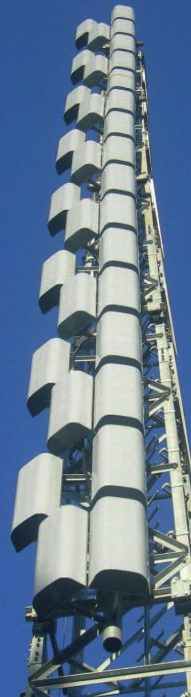
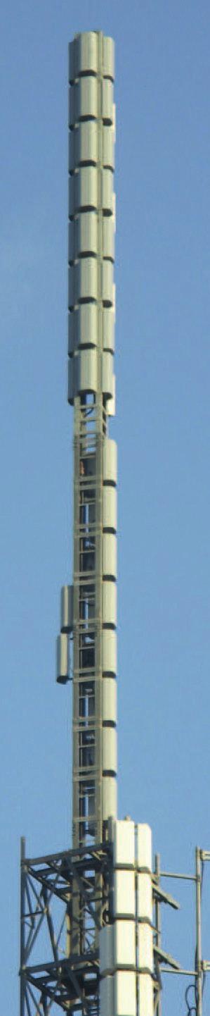
20 Broadcasting Antennas UHF band I230ECX Super-Panel The super-panel is a new, innovative antenna that will satisfy the specific needs of the US market requirements during the repacking phase and set a new standard for the ATSC 3.0 broadcasting antenna, it is the result of an accurate analysis focused on the creation of higher penetration system. Based on the well-known panel antenna technology, proven by more than 40 years of on-site operation, the super-panel is the result of improved dipoles design for the Elliptical operation and a smart reconfiguration to achieve high power, elliptical polarization and low wind load in a compact cylindrical radome. Thanks to its dual 3-1/8 input each driving 8-bay array the total power handling capability is up to 20 kw rms. The extreme advantage of this solution is its panel technology core which results in a true whole UHF Broadband performance and a true Elliptical polarization radiation pattern. The dual 3-1/8 input provides also the flexibility to change the elliptical H/V ratio just changing the phase of the signals feeding the 2 inputs. This means that with the same antenna it is possible to generate a Circular polarization as well as an Horizontal only or Vertical only polarization. The super-panel is available in two version: Narrow Cardioid or Wide-Cardioid pattern design and it is specifically designed for side mount application. It can be used both as a stand-alone or stacked in array configuration. The super-panel is the perfect choice for the Repacking either for a transient solution or for compact and inexpensive main antennas, thanks to its unique characteristics: Real broadband operation, to host at the same time multiple UHF channels serving as a multi-user antenna Real Elliptical polarization, future proof, and the perfect choice for the ATSC 3.0 digital broadcasting standard. Lightweight and compact with a very low wind load: the perfect solution for an easy side-mount installation.
21 filed for international patent Broadcasting Antennas UHF band I230ECN Elliptical UHF Broadband Compact Antenna Broadcasting Antennas MAIN FEATURES Product Code: Electrical characteristics Frequency range Input impedance BROADBAND Freq. Freq MHz MHz 50 ohm Dual Input Flange EIA 3-1/8 Horizontal/Vertical/Circular/ Adjustable Elliptical (*) * Selectable H/V Ratio for each Channel VSWR < 1.2 Gain 12.5 dbd (H Comp.) 13.5 dbd (V Comp.) Electrical Beam Tilt 1 deg. Input Connectors #2 x EIA 3-1/8" Max input Power Mechanical characteristics SUM NARROW CARDIOID PATTERN- 10 kw per Input (20 kw for any configuration) Height Diameter Weight (Mass) Max wind (survival) Projected Area (FPA) 3040 mm (10 feet) 555 mm (21.9 inches) 2157 N (220 Kg 485 lbs) 200 km/h 1.7 m 2 18 ft 2 Materials Cylindrical Radome Fiberglass Color: White Inner lines / Connections Silver Plated Alu/Brass Nuts, & bolts inox steel AISI 304 Tower Side Mount Brackets Hot Dip Galvanized Steel E/EM Radiation Patterns Horizontal Pol. Vertical Pol. (Scaled) Horizontal Pol. Vertical Pol

22 filed for international patent Broadcasting Antennas UHF band I230ECW Elliptical UHF Broadband Compact Antenna Broadcasting Antennas MAIN FEATURES Product Code: Electrical characteristics Frequency range Input impedance BROADBAND Freq. Freq MHz MHz 50 ohm Dual Input Flange EIA 3-1/8 Horizontal/Vertical/Circular/ Adjustable Elliptical (*) * Selectable H/V Ratio for each Channel VSWR < 1.2 Gain Electrical Beam Tilt 11 dbd (H Comp.) 1 deg. 11 dbd (V Comp.) Input Connectors Max input Power Mechanical characteristics Height Diameter Weight (Mass) Materials Cylindrical Radome Fiberglass Color: White Inner lines / Connections Silver Plated Alu/Brass Nuts, & bolts inox steel AISI 304 Tower Side Mount Brackets Hot Dip Galvanized Steel E/EM Radiation Patterns SUM WIDE CARDIOID PATTERN- #2 x EIA 3-1/8" 10 kw per Input (20 kw for any configuration) 3040 mm (10 feet) 555 mm (21.9 inches) 2157 N (220 Kg 485 lbs) Max wind (survival) 200 km/h Projected Area (FPA) 1.7 m 2 18 ft 2 Horizontal Pol. Vertical Pol. (Scaled) Horizontal Pol. Vertical Pol
 Pentagonal")
 -")
 -Coverage")

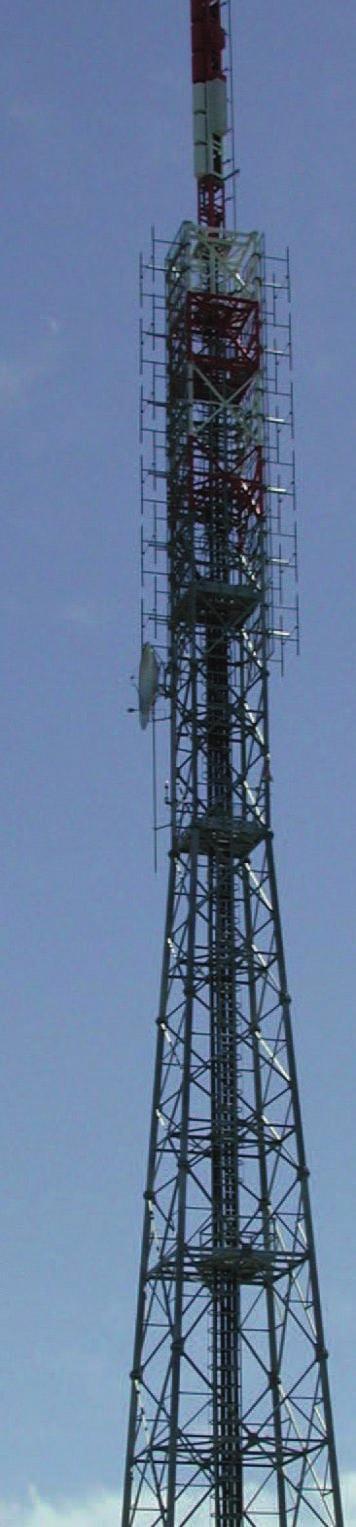
23 Broadcast Antennas Antenna Systems Mechanical support Tampa, FL Antenna System 80 Panels (16 Bays; 120 kw rms) Pentagonal Section Mast with Flanged Interface and Cylindrical radome - Radiation Patterns Measurement (Horizontal & Vertical planes) - VSWR - Pressurization IRTE test Field with 164 ft (50 m) Tower -Antenna Systems Design (Electrical & Mechanical) -Coverage Area Forecast Maps -Interference Analysis -Network Planning -Link Budgets for Radio Links -WinANT (IRTE Antenna System Design software)


24 Broadcast Antennas is the leading Italian Antenna Manufacturing company which has gained in the last years a growing place in the market, due its excellence in design and supply of turn-key projects for DVB-T switch-off. Itech develops high performance Antenna Systems in UHF, VHF and FM bands. It is the only company who manufacture and develop the whole product line: panels, dipoles, Yagi, balanced and unbalanced power dividers, phased cables, flanges, rigid lines, filters, combiners and patch-panels along with custom designed radomes and steel structures for specific projects. Thanks to Italian particular territory, Itech has been involved in many projects for antenna special design, becoming a leader in notch design, electrical tilt definition and custom Vertical and Horizontal diagram special design. We developed special antennas for USA, where delivered antennas for the most important transmitting sites such as Sutro Tower, Boca Raton, Minneapolis, Omaha, etc. Moreover, Itech is a key reference for the radiofrequency design and planning with high end software specially designed for broadcasting market. The antenna system have been developed to comply with all the international standards and with the best state of the art technology. Products Hybrids and combiners; Power splitters up to 6-1/8 (60 KW) Design / Simulations / Manufacture Design and realization of mechanical structure (tower, spines and poles)
25
I TECH S.r.l. Via Pompei n. 35, gallarate (VA) - ITALY VAT / CF PEC
 - ITALY VAT / CF PEC") I TECH S.r.l. Via Pompei n. 35, 21013 gallarate (VA) - ITALY VAT / CF 03479116123 Email: broadcasting@irte.it, PEC Itechsrl@legalmail.it - Tel +39 0331 797286 Broadcast FM NFV71000 FM Dipole FM Band Product
I TECH S.r.l. Via Pompei n. 35, 21013 gallarate (VA) - ITALY VAT / CF 03479116123 Email: broadcasting@irte.it, PEC Itechsrl@legalmail.it - Tel +39 0331 797286 Broadcast FM NFV71000 FM Dipole FM Band Product
Band I (Low VHF) TV Panel Arrays MHz. 606L Series BROADCAST ANTENNA SYSTEMS
 TV Panel Arrays MHz. 606L Series BROADCAST ANTENNA SYSTEMS") Band I (Low VHF) TV Panel Arrays 44-88 MHz L Series The L series of panels are low wind load antennas suitable to provide a customized coverage for any single TV channel in Band I. Low wind load Pressurizable
Band I (Low VHF) TV Panel Arrays 44-88 MHz L Series The L series of panels are low wind load antennas suitable to provide a customized coverage for any single TV channel in Band I. Low wind load Pressurizable
First DTV Antenna on the Hancock Building Chicago, USA
 FRONT COVER (Front Cover Photo) UHF Top-mount Combined Antenna System Highest Power Antenna in Asia (Jakarta, Indonesia) First DTV Antenna on the Hancock Building Chicago, USA JAMPRO ANTENNAS, INC. Your
AL PLUS Series. Low and Medium Power UHF Television Antenna. Low and Medium Power UHF Antenna Systems. Features. Characteristics
 AL PLUS Series Features Fast delivery Light weight, low windload Quick, low-cost installation Four azimuth patterns available Up to 10 kw DTV (23 kw analog) input power rating 8- and 12-bay models Multichannel
700 and 800 MHz Band Slot Antennas
 Low Group Delay, Wide Bandwidth UHF Slot Antennas Omni-directional and Directional Patterns Available Low RFR Models Available Top or Side Mount Models Horizontal, Elliptical, or Circular Polarization
4-Port Antenna Frequency Range Dual Polarization HPBW Adjust. Electr. DT Enhanced Sidelobe Suppression
 Frequency Range Dual Polarization HPB Adjust. Electr. DT Enhanced Sidelobe Suppression Y1 18dB 18dB Downtilt set by hand or by optional RCU (Remote Control Unit) X 65 2 14 X 65 2 14 4-Port Antenna / 65
P300/P350 Series. Vertically Polarized FM Antenna. Features. Characteristics
 Vertically Polarized FM Features Low VSWR, superior VSWR band width, minimal weather related VSWR problems Fully pressurized, internal feed, welded feed connections, series fed radiating elements High
DL Series UHF Top Mount Slot Antennas
 Low Group Delay True Center Fed Design Wide Range of Standard And Custom Azimuth Patterns Available In 8 To 32 Bay Models, In 2 Bay Increments to 65 kw Input Power Ratings Horizontal, Elliptical and Circular
TPV-SFN Series Low RFR VHF Slot Pylon Antennas
 Channel 7-13 (Band III) Low RFR VHF Slot Antenna Omni-directional and Directional Patterns Available Top or Side Mount Models Horizontal, Elliptical, or Circular Polarization Available TPV-SFN Series Low
700 MHz MiMO Yagi Antenna
 Seriously Smart Radios for Linking Critical Communications Infrastructure 700 MHz MiMO Yagi Antenna The 700 MHz MiMO Yagi Antenna with Dual Polarization is a high gain, premium quality antenna with excellent
Low Power FM Antenna Systems
 Low Power FM Antenna Systems J3YF J3YF 3 ELEMENT FM YAGI ANTENNA JAMPRO Yagi 3 Element Antenna Hot Dip Galvanized Steel Directional Radiation Pattern Suitable for Medium and High Power FM Stacked Array
Microwave Antennas making the world smaller
 Microwave Antennas making the world smaller www.procom.dk Index MICROWAVE ANTENNAS 10 GHz Omnidirectional Antennas WGSL 10 2 Parabolic Antennas PRO-10-001/25 3 PRO-10-001/50 4 Accessories PRO-10-... 5
Broadcast Antenna & Service Guide
 Telecommunications Broadcast Antenna & Service Guide Multiple Solutions Various Patterns and Gain Coaxial, Dipole and Patch Designs www.alivetele.com 2 Alive Telecom - Variety of Antenna System Solutions
SpecifIcations DCF 500 DCF 2000 DCF 5000 TCF 3000
 FM Double & Triple Cavity Filters DCF 500 DCF 2000 DCF 5000 TCF 3000 These high quality Cavity Filters are one-quarter wavelength coaxial cavities designed for the 87,5 108 MHz band. They are band pass
Welcome to AntennaSelect Volume 28 October 2016
 Welcome to AntennaSelect Volume 28 October 216 Welcome to Volume 28 of our newsletter, AntennaSelect TM. Every two months we will be giving you an under the radome look at antenna and RF Technology. If
ROTOTILLER. Circularly Polarized FM Antenna. Benefits. Characteristics
 Benefits Low VSWR, superior VSWR band width, and minimal weather related VSWR problems Fully pressurized, internal feed and welded feed connections High input power capacity Modular construction facilitates
MHz Base Station Antennas for Mobile Communications
 27 512 MHz Base Station Antennas for Mobile Communications Photo on title page: Applications for TETRA. Catalogue Issue /4 All data published in previous catalog issues hereby becomes invalid. We reserve
ABOUT JAMPRO CONTINUING THE TRADITION
 JAMPRO ANTENNAS, INC. Your Partner for DTV-DVB-T & HD Radio Solutions- the oldest, most experienced broadcast antenna company in North America with over 50 years of experience providing Complete Turnkey
02680SX Series UHF Mount Dipole Array Series
 02680SX Series UHF Mount Dipole Array Series Page 1 of 11 Description The 02680SX series antennas are 0dB, 3dB and 6dB Gain, Stainless Steel Side Mount Dipole Array antennas, for use in the Commercial
HF ANTENNA HFD2-30 HFD2-30 GENERAL OVERVIEW, WHEN MOUNTED TO TWO 500/30-30 MASTS. Impedance 2,5 max (depending on ground properties)
") HF : HFD2-30 HF ANTENNA HFD2-30 HFD2-30 GENERAL OVERVIEW, WHEN MOUNTED TO TWO 500/30-30 MASTS. HFD2-30 2-30 MHz 28 MHz 50 Ω 2,5 max (depending on ground properties) 6...8 dbi,(depending on ground properties).
HF : HFD2-30 HF ANTENNA HFD2-30 HFD2-30 GENERAL OVERVIEW, WHEN MOUNTED TO TWO 500/30-30 MASTS. HFD2-30 2-30 MHz 28 MHz 50 Ω 2,5 max (depending on ground properties) 6...8 dbi,(depending on ground properties).
MHz Base Station Antennas for Mobile Communications
 27 512 27 512 MHz Base Station Antennas for Mobile Communications Photo on title page: Applications for TETRA. Catalogue Issue 2/27 All data published in previous catalog issues hereby becomes invalid.
MHz. ANT150D, D3, D6-9 DIPOLE AND DIPOLE ARRAY 1 TO 9 dbd
 138-174 MHz ANTD, D3, D6-9 DIPOLE AND DIPOLE ARRAY 1 TO 9 dbd The Telewave ANTD series consists of single, dual, and 4-element di pole array antennas with a precision phasing harness for optimum per formance.
360 inches (915 cm) 240 inches (610 cm) 120 inches (305 cm) 240 inches is the recommended pole length, 360 inches is the recommended free space area
 240 inches (610 cm) 120 inches (305 cm) 240 inches is the recommended pole length, 360 inches is the recommended free space area") FML C/P FM Antenna Right hand C/P Polarization Low wind load area Up to 1 kw Rating per bay Omni-directional Up to 8 kw input per array with power divider options The FML series of antennas are narrow
FML C/P FM Antenna Right hand C/P Polarization Low wind load area Up to 1 kw Rating per bay Omni-directional Up to 8 kw input per array with power divider options The FML series of antennas are narrow
Omnidirectional Antenna Vertical Polarization Indoor and outdoor use
 db Omnidirectional Antenna and outdoor use 17 27 Omni 17 27 6 2dBi 8 41 N female Connector position Bottom or top 17 27 MHz SWR < 1.8 2 dbi Intermodulation IM < 15 dbc (2 x 4 dbm carrier) ertical 5 W (at
SD230T. Frequency Range, MHz Average, 0.6 PEP,1 Average, 3 PEP. <2.0:1 for 3 to 20MHz, <2.5:1 for 2 to 30MHz
 Tactical Semidelta Antennas 2-30MHz SD-T Series The RFS Model SD230T antenna is a transportable, broadband, lightweight, traveling wave antenna for short to medium range ionospheric communications. For
8-Port Antenna Frequency Range Dual Polarization HPBW Adjust. Electr. DT set by hand or by optional RCU (Remote Control Unit)
") Frequency Range Dual Polarization HPB Adjust. Electr. DT R1 790 960 790 960 X 1710 2180 1710 2180 0 10 0 10 0 6 0 6 set by hand or by optional RCU (Remote Control Unit) X 65 65 R2 B1 B2 X X 60 60 8-Port
Frequency Range Dual Polarization HPB Adjust. Electr. DT R1 790 960 790 960 X 1710 2180 1710 2180 0 10 0 10 0 6 0 6 set by hand or by optional RCU (Remote Control Unit) X 65 65 R2 B1 B2 X X 60 60 8-Port
4-Port Antenna Frequency Range Dual Polarization HPBW Adjust. Electr. DT
 4-Port Antenna Frequency Range Dual Polarization HPB Adjust. Electr. DT Y1 Y2 3300 3800 3300 3800 2 12 set by hand or by optional RCU (Remote Control Unit) X X 65 65 4-Port Antenna 3300 3800/3300 3800
4-Port Antenna Frequency Range Dual Polarization HPBW Adjust. Electr. DT
 Frequency Range Dual Polarization HPB Adjust. Electr. DT R1 698 960 Y1 1710 2690 1.5 10 2 8 set by hand or by optional RCU (Remote Control Unit) X 65 X 65 4-Port Antenna 698 960/1710 2690 65 /65 17/18.5dBi
D4000 AND D5000 SERIES OMNIDIRECTIONAL
 INSTRUCTION BOOKLET D4000 AND D5000 SERIES OMNIDIRECTIONAL VHF/UHF ANTENNAS BY www.tacocommunications.com 390146 Rev. F Please Note: A qualified structural engineer should be consulted prior to mounting
ATC Air Traffic Control - Catalogue 13
 ATC Air Traffic Control - Catalogue 1 Via Senatore Simonetta,2 287 Caponago (MB) - Italy tel.: +9 2.95.9.11 fax +9 2.95.9.1.11 e-mail: info@sira.mi.it www.sira.mi.it history SIRA SIRA is a privately owned
6-Port Antenna Frequency Range Dual Polarization HPBW Adjust. Electr. DT set by hand or by optional RCU (Remote Control Unit)
") 6-Port Antenna Frequency Range Dual Polarization HPBW Adjust. Electr. DT R1 790 960 1710 2180 1710 2180 2 14 0 14 0 14 set by hand or by optional RCU (Remote Control Unit) X B1 X B2 65 65 65 X 6-Port Antenna
6-Port Antenna Frequency Range Dual Polarization HPBW Adjust. Electr. DT R1 790 960 1710 2180 1710 2180 2 14 0 14 0 14 set by hand or by optional RCU (Remote Control Unit) X B1 X B2 65 65 65 X 6-Port Antenna
 Electrical Specifications 2-port sector antenna, 2x 1710 2690 MHz, 65 HPBW, RET compatible Provides a future-ready antenna solution with flexibility to reassign antenna, for example GSM 1800 service to
Model VB-23FM 2-Meter 3-Element Beam
 308 Industrial Park Road Starkville, MS 39759 USA Ph: (662) 323-9538 FAX: (662) Model VB-23FM 2-Meter 3-Element Beam [ INSTRUCTION MANUAL Figure 1 Overall View and Boom Detail GENERAL DESCRIPTION This
4-Port Antenna Frequency Range Dual Polarization HPBW Adjust. Electr. DT
 Frequency Range Dual Polarization HPB Adjust. Electr. DT R1 790 960 B1 1710 2180 0 14 0 8 set by hand or by optional RCU (Remote Control Unit) X 65 X 65 4-Port Antenna 790 960/1710 2180 65 /65 14.5/17.5dBi
The quality you expect at the price you want to pay. Available at: 1 (888) (866)
 (866)") The quality you expect at the price you want to pay Available at: www.wirelessource.ca 1 (888) 430-0660 1 (866) 244-4844 October 2014 VHF Mobile Antennas... P1-5 UHF Mobile Antennas... P6-9 CB Mobile Antennas...
The quality you expect at the price you want to pay Available at: www.wirelessource.ca 1 (888) 430-0660 1 (866) 244-4844 October 2014 VHF Mobile Antennas... P1-5 UHF Mobile Antennas... P6-9 CB Mobile Antennas...
HyperLink Wireless High Density 2.4/5 GHz Four Element Dual Polarized Flat Panel Antenna Model: HG HDP-4NF
 HyperLink Wireless High Density 2.4/5 GHz Four Element Dual Polarized Flat Panel Antenna Model: HG2458-13HDP-4NF Features Four independent antennas, two vertical and two horizontal Narrow beamwidth for
4-Port Antenna Frequency Range Dual Polarization HPBW Adjust. Electr. DT
 4-Port Antenna Frequency Range Dual Polarization HPBW Adjust. Electr. DT R1 0.5 7 0 6 set by hand or by optional RCU (Remote Control Unit) X 90 B1 X 90 4-Port Antenna / 90 /90 16.5/18i 0.5 7 /0 6 T Type
HP ProCurve 6.9/7.7dBi Dual Band Directional Antenna (J8999A) Guide
 Guide") HP ProCurve 6.9/7.7dBi Dual Band Directional Antenna (J8999A) Guide SAFETY The HP ProCurve J8999A and all associated equipment should be installed in accordance with applicable local and national electrical
HP ProCurve 6.9/7.7dBi Dual Band Directional Antenna (J8999A) Guide SAFETY The HP ProCurve J8999A and all associated equipment should be installed in accordance with applicable local and national electrical
Corporate Antenna Solutions MHz MHz
 Corporate Antenna Solutions 380-512MHz 746-870MHz 1 About RFI RFI is a global technology solutions company, specialising in wireless coverage. RFI has one of the largest, most innovative and experienced
6-Port Antenna Frequency Range Dual Polarization HPBW Adjust. Electr. DT set by hand or by optional RCU (Remote Control Unit)
") Frequency Range Dual Polarization HPB Adjust. Electr. DT 698 960 1710 2690 1710 2690 1 12 2 12 2 12 set by hand or by optional RCU (Remote Control Unit) X X 65 65 65 X 6-Port Antenna 698 960/1710 2690/1710
Frequency Range Dual Polarization HPB Adjust. Electr. DT 698 960 1710 2690 1710 2690 1 12 2 12 2 12 set by hand or by optional RCU (Remote Control Unit) X X 65 65 65 X 6-Port Antenna 698 960/1710 2690/1710
ProCurve 7 dbi Dual Band Directional antenna
 GROUNDING System grounding and lightning protection are essential, especially for exterior-mounted antennas exposed to the elements. Never install an antenna where it may fall and contact electrical lines
LOG PERIODIC DIPOLES TRANSMIT-RECEIVE
 3E LOG PERIODIC DIPOLES LINEARLY POLARIZED LPD series antennas are linearly polarized medium gain, log periodic antennas for broadband applications. The LPD s high quality aluminum construction with all
Frequency Range (MHz) CONNECTOR TYPE Female. Manual Electrical Tilt (MET) --- Three Sectors
 CONNECTOR TYPE Female. Manual Electrical Tilt (MET) --- Three Sectors") Tri band, tri-sector antenna, 18 connectors Independent tilt on each band 2-10 / 0-10 / 0-10 Independent azimuth panning ±15 on each sector MET and RET versions, 3GPP/AISG2.0 Our patented, RET module controlling
Tri band, tri-sector antenna, 18 connectors Independent tilt on each band 2-10 / 0-10 / 0-10 Independent azimuth panning ±15 on each sector MET and RET versions, 3GPP/AISG2.0 Our patented, RET module controlling
6-Port Antenna Frequency Range Dual Polarization HPBW Adjust. Electr. DT set by
 6-Port Antenna Frequency Range Dual Polarization HPBW Adjust. Electr. DT set by R1 Y1 Y2 698 960 1710 2690 1710 2690 X X X 65 65 65 1 10 2.5 12 2.5 12 6-Port Antenna 698 960/1710 2690/1710 2690 65 /65
8-Port Antenna Frequency Range Dual Polarization HPBW Adjust. Electr. DT
 Frequency Range Dual Polarization HPB Adjust. Electr. DT R1 790 960 B1 1710 1880 B2 1920 2170 Y1 2490 2690 X X X X 65 65 65 65 0.5 9.5 2 8 2 8 2 8 set by hand or by optional RCU (Remote Control Unit) 8-Port
Welcome to AntennaSelect Volume 20 June New FMM - mid power FM antennas
 Welcome to AntennaSelect Volume 20 June 2015 Welcome to Volume 20 of our newsletter, AntennaSelect TM. Each month we will be giving you an under the radome look at antenna and RF technology. If there are
Mast Mount Omnidirectional (MMO) Antennas
 Antennas") Mast Mount Omnidirectional Antennas Mast Mount Omnidirectional (MMO) Antennas The MMO series base antenna provides outstanding coverage in a rugged U.V. stable, plastic radome with an aluminum base that
Mast Mount Omnidirectional Antennas Mast Mount Omnidirectional (MMO) Antennas The MMO series base antenna provides outstanding coverage in a rugged U.V. stable, plastic radome with an aluminum base that
Type 2701 and 2702 Series GRANGER Horizontally Polarized, Log-Periodic HF Antennas
 Type 2701 and 2702 Series GRANGER Horizontally Polarized, Log-Periodic HF Antennas 2-30 MHz Frequency Range Up to kw Average, kw Peak Power Rating Horizontal Polarization 2.0:1 Maximum VSWR Short-to-Medium-Range
MHz KATHREIN-Antennas and Antenna Line Products. For Public Safety, Ports, Airports, Distribution, Public Transport, Utilities
 27 512 MHz KATHREIN-Antennas and Antenna Line Products For Public Safety, Ports, Airports, Distribution, Public Transport, Utilities Photo on title page: Applications for TETRA. Catalogue Issue 1/211 All
6-Port Antenna Frequency Range Dual Polarization HPBW Adjust. Electr. DT set by hand or by optional RCU (Remote Control Unit)
") Frequency Range Dual Polarization HPB Adjust. Electr. DT 698 960 1710 2690 1710 2690 1.5 10 0 10 2 10 set by hand or by optional RCU (Remote Control Unit) X X 65 65 65 X 6-Port Antenna 698 960/1710 2690/1710
Frequency Range Dual Polarization HPB Adjust. Electr. DT 698 960 1710 2690 1710 2690 1.5 10 0 10 2 10 set by hand or by optional RCU (Remote Control Unit) X X 65 65 65 X 6-Port Antenna 698 960/1710 2690/1710
Panel Antenna Solutions. Low Profile, Low PIM, Directional Antennas
 Panel Antenna Solutions Low Profile, Low PIM, Directional Antennas About RFI RFI is a global technology solutions company, specialising in wireless coverage. RFI has one of the largest, most innovative
INSTRUCTION MANUAL. Specifications Mechanical. 1 5/8 to 2 1/16 O.D. (41mm to 52mm)
") 308 Industrial Park Road Starkville, MS 39759 USA Ph: (662) 323-9538 FAX: (662) 323- General Description Model VB-25FM 2-Meter 5 Elements Beam INSTRUCTION MANUAL This antenna is a 5-element, 2-meter beam
308 Industrial Park Road Starkville, MS 39759 USA Ph: (662) 323-9538 FAX: (662) 323- General Description Model VB-25FM 2-Meter 5 Elements Beam INSTRUCTION MANUAL This antenna is a 5-element, 2-meter beam
HyperLink Wireless 2.4/ 5 GHz Dual Band / Dual Polarized Omni Antenna Model: HG DPU
 HyperLink Wireless 2.4/ 5 GHz Dual Band / Dual Polarized Omni Antenna Model: HG2458-11DPU Applications 2.4/5 GHz IEEE 802.11a/b/g applications Supports 1x2, 2x2 and 4x4 MIMO AP/Routers WiMax, WISP and
MOUNTING INSTRUCTIONS
 Standard Mounting Bracket Tilting Bracket* Mounting example Right side for upper tilt from 0 to 20 20 Spare parts: p/n SA197 Materials: extruded aluminum Hardware: stainless & zinc plated steel Dimensions
AIR BAND ANTENNAS SUMMARY
 SUMMARY Collinear 85 140 MHz, any 5% Coaxial Dipoles 118 136 MHz, any 3% Sidemount Dipoles 118 136 MHz Stack Dipole Arrays 118 136 MHz Monocones 118 136 MHz Discones 70 1000 MHz G12 Air Band Collinear
Antennas. You re heard, loud and clear.
 Antennas You re heard, loud and clear. PIM-RATED ANTENNAS COL Series VHF and UHF Meander Collinear The Meander Collinear Antennas, available in both the VHF, UHF and 700/800 MHz bands, have been specifically
Independent tilt for high bands and single tilt for low bands
 Electrical Specifications 8-port sector antenna, 2x 698 787, 2x 824-894 and 4x 1695 2360 MHz, 65 HPBW, 3x RET and low bands have diplexers Interleaved dipole technology providing for attractive, low wind
FEDERAL COMMUNICATIONS COMMISSION (FCC) COMPLIANCE STUDY ON TELECOMMUNICATION FACILITY
 COMPLIANCE STUDY ON TELECOMMUNICATION FACILITY") FEDERAL COMMUNICATIONS COMMISSION (FCC) COMPLIANCE STUDY ON TELECOMMUNICATION FACILITY Prepared for: Site No.: CA-SAC112 EAST ARDEN 5107 FAIR OAKS BOULEVARD CARMICHAEL, CA 95608 SEPTEMBER 26/07, REV. 0
FEDERAL COMMUNICATIONS COMMISSION (FCC) COMPLIANCE STUDY ON TELECOMMUNICATION FACILITY Prepared for: Site No.: CA-SAC112 EAST ARDEN 5107 FAIR OAKS BOULEVARD CARMICHAEL, CA 95608 SEPTEMBER 26/07, REV. 0
Multi-Band Quasi-Omni Antenna
 DATA SHEET Two foot (0.6 m), multi-band, four port quasi-omni antenna with 360 of coverage, covering 698-896 MHz and 1710-2360 MHz frequencies Two wide high band ports covering 1710-2360 MHz and two wide
M2 Antenna Systems, Inc. Model No: 2M7
 M2 Antenna Systems, Inc. Model No: 2M7 SPECIFICATIONS: Model... 2M7 Frequency Range... 144 To 148 MHz *Gain... 12.3 dbi Front to back... 20 db Typical Beamwidth... E=43 H=50 Feed type... T Match Feed Impedance....
Advanced Test Equipment Rentals ATEC (2832)
") Established 1981 Advanced Test Equipment Rentals www.atecorp.com 800-404-ATEC (2832) LOG PERIODIC DIPOLES 20 MHz - 18 GHz TRANSMIT - RECEIVE SPECIFICATIONS ELECTRICAL Impedance: 50 ohms INDIVIDUALLY CALIBRATED
Established 1981 Advanced Test Equipment Rentals www.atecorp.com 800-404-ATEC (2832) LOG PERIODIC DIPOLES 20 MHz - 18 GHz TRANSMIT - RECEIVE SPECIFICATIONS ELECTRICAL Impedance: 50 ohms INDIVIDUALLY CALIBRATED
Wideband Quasi-Omni Antenna
 DATA SHEET Two foot (0.5 m), two port, quasi-omni antenna with uniform horizontal beamwidths covering the extended band from 1710-2690 MHz 360 of coverage area across all bands of operation in a single
6-Port Antenna Frequency Range Dual Polarization HPBW Adjust. Electr. DT set by hand or by optional RCU (Remote Control Unit)
") 6-Port Antenna Frequency Range Dual Polarization HPBW Adjust. Electr. DT R1 698 960 1710 2690 1710 2690 1.5 10 0 10 2 10 set by hand or by optional RCU (Remote Control Unit) X Y1 X Y2 65 65 65 X 6-Port
6-Port Antenna Frequency Range Dual Polarization HPBW Adjust. Electr. DT R1 698 960 1710 2690 1710 2690 1.5 10 0 10 2 10 set by hand or by optional RCU (Remote Control Unit) X Y1 X Y2 65 65 65 X 6-Port
Panel Antenna Solutions
 RFI Panel Antenna Solutions Panel Antenna Solutions Low Profile, Low PIM, Directional Antennas About RFI RFI Panel Antenna Solutions RFI is a global technology solutions company, specialising in wireless
Cisco Aironet Six-Element Dual-Band MIMO Patch Array Antenna (AIR-ANT25137NP-R)
") Cisco Aironet Six-Element Dual-Band MIMO Patch Array Antenna (AIR-ANT25137NP-R) August 2, 2013 This document describes the AIR-ANT25137NP-R antenna and provides instructions for mounting it. The antenna
Cisco Aironet Six-Element Dual-Band MIMO Patch Array Antenna (AIR-ANT25137NP-R) August 2, 2013 This document describes the AIR-ANT25137NP-R antenna and provides instructions for mounting it. The antenna
M2 Antenna Systems, Inc. Model No: 2M4
 M2 Antenna Systems, Inc. Model No: 2M4 SPECIFICATIONS: Model... 2M4 Frequency Range... 144 To 148 MHz *Gain... 9.6 dbi Front to back... 20 db Typical Beamwidth... E=54 H=74 Feed type... T Match Feed Impedance....
Model:OS NM GHz 5.875GHz 12dBi Outdoor Mini Omni-Directional Antenna. Accessories
 5.125GHz 5.875GHz 12dBi Outdoor Mini Omni-Directional Antenna OS-515912-NM is a high quality of the ISM Band 5.125-5.875ghz Omni-directional antenna can be used for IEEE 802.11a, wireless networks can
Antenna Technology Bootcamp. NTA Show 2017 Denver, CO
 Antenna Technology Bootcamp NTA Show 2017 Denver, CO Review: How a slot antenna works The slot antenna is a TEM-Mode coaxial structure. Coupling structures inside the pylon will distort and couple to the
12-Port Antenna Frequency Range Dual Polarization HPBW Adjust. Electr. DT set by
 12-Port Antenna Frequency Range Dual Polarization HPB Adjust. Electr. DT set by R1 R2 Y1 Y2 Y3 Y4 698 803 824 894 1695 2690 1695 2690 1695 2690 1695 2690 X X X X X X 65 65 65 65 65 65 1.5 10 1.5 10 2.5
Chapter 6 Antenna Basics. Dipoles, Ground-planes, and Wires Directional Antennas Feed Lines
 Chapter 6 Antenna Basics Dipoles, Ground-planes, and Wires Directional Antennas Feed Lines Some General Rules Bigger is better. (Most of the time) Higher is better. (Most of the time) Lower SWR is better.
12-Port Antenna Frequency Range Dual Polarization HPBW Adjust. Electr. DT set by
 12-Port Antenna Frequency Range Dual Polarization HPB Adjust. Electr. DT set by R1 R2 Y1 Y2 Y3 Y4 698 803 824 894 1695 2690 1695 2690 1695 2690 1695 2690 X X X X X X 65 65 65 65 65 65 2 12 2 12 2 14 2
AN-80i. Advanced Broadband Wireless Infrastructure Solutions. 5 GHz Antenna Guide
 AN80i Advanced Broadband Wireless Infrastructure Solutions 5 GHz 70001150102a Proprietary Redline Communications 2011 Page 1 of 18 February 18, 2011 AN80i Copyright Information All rights reserved February
2-Port Antenna Frequency Range Dual Polarization HPBW Adjust. Electr. DT Enhanced Sidelobe Suppression
 2-Port Antenna Frequency Range Dual Polarization HPBW Adjust. Electr. DT Enhanced Sidelobe Suppression 1710 2690 18 Downtilt set by hand or by optional RCU (Remote Control Unit) X 65 2 14 2-Port Antenna
db Systems Model 5100A-HS-ICE DME Antenna
 Installation Manual db Systems Model 5100A-HS-ICE DME Antenna HEATED RADOME HIGH PERFORMANCE DME ANTENNA MANUFACTURER db SYSTEMS, INC. 2005 SOUTH TURF SOD ROAD HURRICANE, UT 84737 DATE OF ORIGINAL ISSUE:
Laird Technologies Base Station Antennas
 Omnidirectional Laird Technologies Base Station Antennas Laird Technologies offers an extensive array of base station and in-building wireless antennas. Responding to the ever-increasing variety of frequencies
524/527/527B Super High Gain Log-Periodic Antennas
 803C XXXXX 524/527/527B Super High Gain Log-Periodic Antennas Maximize gain and bandwidth with an exceptionally small structure. Highly reliable communications on long-range circuits require antennas with
Low Wideband Quasi-Omni Antenna
 DATA SHEET Two foot (0.7 m), singleband, two port quasi-omni antenna with 360 of coverage, covering 694-960 MHz frequencies Two wide low band ports covering 694-960 MHz in a low weight and low profile
Small Cell 65 Degree Panel Antenna
 DATA SHEET Small Cell Sector antenna optimized over the PCS (1850-1995 MHz) and BRS (2496 to 2690 MHz) bands Cross-Pol design for 2x2 MIMO Excellent upper sidelobe suppression Designed for superior Front
FEI TENG WIRELESS TECHNOLOGY CO., LTD. APPROVAL SHEET
 Customer Date 2014 / 05/ 08 Product OA-3088M02B-BF 30MHz 88MHz VHF Broadband Antenna REV 1 FEI TENG WIRELESS TECHNOLOGY CO., LTD. APPROVAL SHEET Customer Approved By Approve Chief Responsible 30MHz 88MHz
4-Port Antenna Frequency Range Dual Polarization HPBW Adjust. Electr. DT set by
 4-Port Antenna Frequency Range Dual Polarization HPB Adjust. Electr. DT set by R1 698 960 X 65 2 12 R2 698 960 X 65 2 12 4-Port Antenna 698 960/698 960 65 /65 15.5/15.5dBi 2 12 /2 12 T Type No. 80010901
Superseded. Small Cell IDA Antenna IDA-30F-KE-H2 DATA SHEET. Overview. Applications
 DATA SHEET Overview Applications 2 ports covering bands between 698 and 960 MHz and 2 ports covering bands between 1695 and 2690 MHz Constant 30 vertical by 30 horizontal beamwidth MIMO and SISO capable
CVC L ANTENNA GATES GATES RING. Designed for FM Stereo and Multiplex broadcasting Shunt Fed -Binary Adjustment (Pat. Pending).
.") GATES GATES CVC L O D FM RING ANTENNA Designed for FM Stereo and Multiplex broadcasting Shunt Fed -Binary Adjustment (Pat. Pending). Lowest possible VSWR Top, side or irside tower mounting Optional deicing
GATES GATES CVC L O D FM RING ANTENNA Designed for FM Stereo and Multiplex broadcasting Shunt Fed -Binary Adjustment (Pat. Pending). Lowest possible VSWR Top, side or irside tower mounting Optional deicing
ANTENNAS FEED POINTS. An antenna is a mechanical structure by which electromagnetic waves are sent out or received.
 ANTENNAS An antenna is a mechanical structure by which electromagnetic waves are sent out or received. An antenna accomplishes this by being made so that its structure will be resonant at the frequency
6-Port Antenna Frequency Range Dual Polarization HPBW Adjust. Electr. DT
 6-Port Antenna Frequency Range Dual Polarization HPBW Adjust. Electr. DT R1 1710 1880 0 10 0 6 0 6 set by hand or by optional RCU (Remote Control Unit) B1 B2 1920 2170 6-Port Antenna /1710 1880/1920 2170
(3 m cable + FME(f))
)") MINI FLEX DUAL Dual frequency self-adhesive linear patch-antenna for in-car window mounting (on screen) * VERY EASY INSTALLATION * FLEXIBLE DESIGN 890-960 and 1710-1880 MHz DIMENSIONS Linear 0/0 db See
MINI FLEX DUAL Dual frequency self-adhesive linear patch-antenna for in-car window mounting (on screen) * VERY EASY INSTALLATION * FLEXIBLE DESIGN 890-960 and 1710-1880 MHz DIMENSIONS Linear 0/0 db See
4-Port Antenna Frequency Range Dual Polarization HPBW Adjust. Electr. DT
 4-Port Antenna Frequency Range Dual Polarization HPB Adjust. Electr. DT R1 790 960 0 10 2 8 set by hand or by optional RCU (Remote Control Unit) X 65 Y1 1710 2690 X 65 4-Port Antenna 790 960/1710 2690
By Paul Melbourne G8GML and Ian Waters G3KKD.
 23cm Panel Antennas By Paul Melbourne G8GML and Ian Waters G3KKD. This article describes a range of panel antennas developed by G8GML. It is a sequel to an article by John Stockley, G8MMY, published in
6-port sector antenna, 2x and 4x MHz, 65 HPBW, RET compatible
 6-port sector antenna, 2x 790 960 and 4x 1710 2690 MHz, 65 HPBW, 3x RET with manual override OBSOLETE This product was discontinued on: June 1, Replaced By RVV65A-M RVV65A-3X2 6-port sector antenna, 2x
PANEL ANTENNAS WITH ONLY HIGH BAND ARRAYS
 PANEL ANTENNAS WITH ONLY HIGH BAND ARRAYS 54 April 2015 Ultra-wideband antennas designed to handle 2G, 3G networks and MIMO configurations for LTE on 1.8 / 2.1 / 2.6 networks. HighBand April 2015 55 (2x)
Special Communication
 CATALOGUE 2018/2 Special Counication Antennas and Solutions for Blue Light and Armed Forces SPECIAL COMMUNICATION Who we are and what we stand for Kathrein is a specialist for reliable, high-quality counication
Antenna Design Seminar
 Antenna Design Seminar What we are going to cover This seminar will cover the design concepts of a variety of broadcast antennas that relates to the design of TV and FM antennas. We will first look at
4-Port Antenna Frequency Range Dual Polarization HPBW Adjust. Electr. DT
 4-Port Antenna Frequency Range Dual Polarization HPB Adjust. Electr. DT R1 790 960 0.5 9.5 0 6 set by hand or by optional RCU (Remote Control Unit) X 65 B1 1710 2180 X 65 4-Port Antenna 790 960/1710 2180
Standard Rigid Line STD775 Series
 Specifications Product Series STD775 Size 7-3/16 Impedance 75 ± 0.5-ohm Maximum Channel 69 Velocity, % 99.8 Peak Rating, 1400 Net Weight, lb/ft (kg/m) 8.21 Outer Conductor Outside Diameter, in (mm) 7.15
Product Catalogue. WiMAX & Wireless Antennas. permission of All Max Electronics Ltd. Specifications subject to change without prior notice.
 Ver. 2.4 Ver. 2.4 REVISED MARCH 2014 All Max Electronics Ltd. Product Catalogue WiMAX & Wireless Antennas Revision: 2.4 This document is the exclusive property of All Max Electronics Ltd. and should not
Repack Space Squeeze How Long is That FM Antenna? Multi-Bay Antennas and AM Translators
 Welcome to AntennaSelect Volume 27 August 2016 Welcome to Volume 27 of our newsletter, AntennaSelect TM. Every two months we will be giving you an under the radome look at antenna and RF Technology. If
ANT dbi Fixed Mount 3G/4G/LTE Yagi Directional Antenna
 Applications 3G / 4G / LTE Modems & Routers 2.4 GHz WiFi / WLAN Access Points 900 MHz Point-to-Point Radios Signal Boosters / Amplifiers Wireless Backhaul Product Features 11 dbi Peak Gain Compatible with
M2 Antenna Systems, Inc. Model No: 20M5LD
 M2 Antenna Systems, Inc. Model No: 20M5LD SPECIFICATIONS: Model... 20M5LD Frequency Range... 14.0 14.350 MHz *Gain (Full Band)... 10.2 dbi Typical Front to back... 23 db Typical Beamwidth... E=50 / H=66
CHAPTER 8 ANTENNAS 1
 CHAPTER 8 ANTENNAS 1 2 Antennas A good antenna works A bad antenna is a waste of time & money Antenna systems can be very inexpensive and simple They can also be very expensive 3 Antenna Considerations